EP3504521B1 - Friction measurement for electromechanical liquid level gauges - Google Patents
Friction measurement for electromechanical liquid level gauges Download PDFInfo
- Publication number
- EP3504521B1 EP3504521B1 EP17847186.8A EP17847186A EP3504521B1 EP 3504521 B1 EP3504521 B1 EP 3504521B1 EP 17847186 A EP17847186 A EP 17847186A EP 3504521 B1 EP3504521 B1 EP 3504521B1
- Authority
- EP
- European Patent Office
- Prior art keywords
- displacer
- physical quantity
- esg
- drum
- servo motor
- Prior art date
- Legal status (The legal status is an assumption and is not a legal conclusion. Google has not performed a legal analysis and makes no representation as to the accuracy of the status listed.)
- Active
Links
Images


Classifications
-
- G—PHYSICS
- G01—MEASURING; TESTING
- G01F—MEASURING VOLUME, VOLUME FLOW, MASS FLOW OR LIQUID LEVEL; METERING BY VOLUME
- G01F23/00—Indicating or measuring liquid level or level of fluent solid material, e.g. indicating in terms of volume or indicating by means of an alarm
- G01F23/0023—Indicating or measuring liquid level or level of fluent solid material, e.g. indicating in terms of volume or indicating by means of an alarm with a probe suspended by a wire or thread
-
- G—PHYSICS
- G01—MEASURING; TESTING
- G01F—MEASURING VOLUME, VOLUME FLOW, MASS FLOW OR LIQUID LEVEL; METERING BY VOLUME
- G01F23/00—Indicating or measuring liquid level or level of fluent solid material, e.g. indicating in terms of volume or indicating by means of an alarm
- G01F23/80—Arrangements for signal processing
- G01F23/802—Particular electronic circuits for digital processing equipment
- G01F23/804—Particular electronic circuits for digital processing equipment containing circuits handling parameters other than liquid level
-
- G—PHYSICS
- G01—MEASURING; TESTING
- G01F—MEASURING VOLUME, VOLUME FLOW, MASS FLOW OR LIQUID LEVEL; METERING BY VOLUME
- G01F25/00—Testing or calibration of apparatus for measuring volume, volume flow or liquid level or for metering by volume
- G01F25/20—Testing or calibration of apparatus for measuring volume, volume flow or liquid level or for metering by volume of apparatus for measuring liquid level
-
- B—PERFORMING OPERATIONS; TRANSPORTING
- B65—CONVEYING; PACKING; STORING; HANDLING THIN OR FILAMENTARY MATERIAL
- B65G—TRANSPORT OR STORAGE DEVICES, e.g. CONVEYORS FOR LOADING OR TIPPING, SHOP CONVEYOR SYSTEMS OR PNEUMATIC TUBE CONVEYORS
- B65G43/00—Control devices, e.g. for safety, warning or fault-correcting
-
- G—PHYSICS
- G05—CONTROLLING; REGULATING
- G05B—CONTROL OR REGULATING SYSTEMS IN GENERAL; FUNCTIONAL ELEMENTS OF SUCH SYSTEMS; MONITORING OR TESTING ARRANGEMENTS FOR SUCH SYSTEMS OR ELEMENTS
- G05B2219/00—Program-control systems
- G05B2219/30—Nc systems
- G05B2219/42—Servomotor, servo controller kind till VSS
- G05B2219/42271—Monitor parameters, conditions servo for maintenance, lubrication, repair purposes
Landscapes
- Physics & Mathematics (AREA)
- Fluid Mechanics (AREA)
- General Physics & Mathematics (AREA)
- Engineering & Computer Science (AREA)
- Signal Processing (AREA)
- Level Indicators Using A Float (AREA)
Description
- Disclosed embodiments relate to electromechanical liquid level gauges that use the servo principle.
- Electromechanical liquid level servo gauges (ESGs) are used for the accurate measurement of product level and the water interface level in bulk storage tanks used for typical hydrocarbons (often referred to as fuel and oil) as well as for a variety of other liquid chemicals. These products range from very light chemicals, including so-called LPG's (mixtures of propane and butane or even liquefied natural gas (LNG)) to all types of refined products such as naphtha, gasoline, diesel, jet fuels, lubricants and all types of chemicals,
- The servo principle is based on the measurement of the apparent weight of a displacer that is within the liquid in the tank. The displacer is a mechanical body suspended on a strong thin measuring wire, where the displacer material has a higher density than the liquid to be measured. The measurement wire is wound on a high accuracy machined grooved drum with a calibrated circumference that is coupled to a detection shaft that is coupled to a worm wheel (or servo motor) by ball bearings. The apparent weight resulting from the weight of the displacer minus the weight of the displaced liquid product is measured and is then used by a computing device such as a microcontroller with the servo motor used to rotate drum in order to position the displacer at a different height in the tank.
- By rotating the drum the wire is spooled up or paid out into the tank and the displacer is raised or lowered until the measured apparent weight equals the programmed set point. For safety reasons typically a magnetic coupling (using pole pairs) may be located between drum and electronics (motor, microcontroller, electronics, etc.) as many of the liquids products which are commonly stored in bulk storage tanks are flammable and typically need an explosion safe design. The displacer being denser as compared to the density of the liquid product in the tank is basically kept at the same level using Archimedes law which indicates that the upward buoyant force that is exerted on a body immersed in a fluid, whether fully or partially submerged, is equal to the weight of the fluid that the body displaces.
- An example of a currently used system can be found in
WO2016037815A1 , which discloses an electromechanical fill state measuring device comprising at least one displacement element which is connected to at least one measuring drum by means of a measuring wire in a windable manner, at least one measuring shaft to which the measuring drum is mechanically connected in a rigid manner and is mounted in at least one rotary bearing, at least one weight measuring device which ascertains the current weight of the displacement element and the measuring wire, and at least one servomotor which is coupled to the measuring shaft and which adjusts the measuring shaft according to an ascertained weight measurement such that the relative movement of the measuring drum generated by a change of the liquid level to be measured is ascertained. Wherein the device includes a calibration mode of the weight measuring device of the electromechanical fill state measuring device, wherein freely suspended displacement elements with a defined mass are provided on the measuring wire in order to ascertain the weight of the elements; a specified rotational movement of the measuring drum is provided after each change of the freely suspended displacement elements with a defined mass; and the ascertained weight of the displacement elements is provided as calibration values for a weight measurement. - This Summary is provided to introduce a brief selection of disclosed concepts in a simplified form that are further described below in the Detailed Description including the drawings provided. This Summary is not intended to limit the claimed subject matter's scope.
- The invention comprises a method of measuring friction according to claim 1 and an electromechanical liquid level gauge that uses a servo principle (EGS) according to
claim 8. - Disclosed embodiments recognize one limitation of conventional electromechanical liquid level servo gauges (ESGs) is the inability to measure friction in the ESG while in the field, where extra friction can degrade the ESG's level measurement accuracy. Moreover, over time the friction may increase for an ESG installed in the field. This means that there is no indication provided when service of the ESG is needed, such as to initiate maintenance to oil the ball bearings associated with the servo motor. Another related problem is that there is no known test to check the behavior of new ball bearings during manufacturing of ESGs.
- Disclosed embodiments also simplify maintenance of the ESG. A servo gauge being a mechanical device needs maintenance and service engineers to check to determine whether the bearings are still in good shape. Disclosed embodiments greatly ease diagnostics of the bearings and can be used to add self-diagnostics, where the ESG itself can indicate it needs maintenance.
- Disclosed embodiments solve this unmet need for friction measurement and diagnostics for ESGs by providing automatic methods of friction measurement of an ESG including the ball bearings associated with the servo motor and positioning bearings on the drive shaft for holding the drive shaft and keeping the drive shaft positioned in the housing. Disclosed embodiments are applicable when the ESG is installed (on site, e.g., of a plant) and also during manufacturing of the ESG to prove that the friction is at an acceptably low level before shipping the ESG to a customer.
- One disclosed embodiment comprises an ESG including a displacer on a wire from a measuring drum for causing a torque on the drum, a servo motor with a gear coupled by a drive shaft for rotating the drum, wherein a change in a liquid level causes a change in a counterforce to move the ESG out of balance, and a force transducer is positioned for measuring the torque on the drum and for converting the torque into a physical quantity such as frequency. Alternatively, not forming part of the claimed invention, the torque can generally be converted to another physical quantity such as a voltage or a current. As used herein a "physical quantity" is a physical property that can be quantified, where a physical property is any property that is measurable, whose value describes a state of a physical system, such as within a tank gauging system.
- A processor implements a disclosed automatic friction determination algorithm. A first move moves the displacer in a first direction for ≥1 motor step(s) to a first position and first physical quantity data including at least a first physical quantity (Q1) is then measured by the transducer. Second moving moves the displacer in an opposite direction ≥1 step(s) to reach a second displacer position, and second physical quantity data including at least a second physical quantity (Q2) is then measured by the transducer. A hysteresis measure (e.g., a hysteresis value) is then determined from the first and second physical quantity data. In one embodiment Q1 is the total physical quantity change (or difference) resulting from moving the displacer in one direction, and Q2 is the total physical quantity shift resulting from moving the displacer in the other direction, and the absolute value of the difference, |Q1-Q2|, is calculated to determine a hysteresis value which indicates the level of friction.
-
-
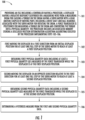
FIG. 1 is a flow chart that shows steps in an example method of automatically measuring the friction of an ESG, according to an example embodiment. -
FIG. 2A is a depiction of an example ESG implementing automatic measuring of friction, according to an example embodiment. -
FIG. 2B is a block diagram of an example ESG implementing automatic measuring of friction, according to an example embodiment. -
FIGs. 3A and 3B show motor position and average frequency data before lubrication of the ball bearings of the ESG, andFIG. 3C and 3D show the motor position and average frequency data after lubrication of the ball bearings of the ESG. - Disclosed embodiments are described with reference to the attached figures, wherein like reference numerals are used throughout the figures to designate similar or equivalent elements. The figures are not drawn to scale and they are provided merely to illustrate certain disclosed aspects. Several disclosed aspects are described below with reference to example applications for illustration. It should be understood that numerous specific details, relationships, and methods are set forth to provide a full understanding of the disclosed embodiments.
- In other instances, well-known structures or operations are not shown in detail to avoid obscuring certain aspects. This Disclosure is not limited by the illustrated ordering of acts or events, as some acts may occur in different orders and/or concurrently with other acts or events. Furthermore, not all illustrated acts or events are required to implement a methodology in accordance with the embodiments disclosed herein.
- Disclosed embodiments include methods for automatically measuring the friction in the ESG including the ball bearings associated with the servo motor. The wire position is generally set to start with the displacer above the liquid (or other material) in the tank. The displacer is commanded in the upward or downward direction, typically ≥ 8 motor steps. The physical quantity frequency of the force transducer is then measured to provide first physical quantity data including at least a first physical quantity (Q1). The displacer is commanded in the opposite direction, again typically ≥ 8 motor steps. The physical quantity of the force transducer is again measured to provide second physical quantity data including at least a second physical quantity (Q2). A hysteresis measure (e.g., a hysteresis value) is determined from the first and second physical quantity data. As described above, in one embodiment Q1 is the total physical quantity change (or difference) resulting from moving the displacer in one direction, and Q2 is the total physical quantity shift resulting from moving the displacer in the other direction, and |Q1-Q2| is calculated to determine a hysteresis value which indicates a level of friction or state of the bearings, such as low, moderate, high, or very high (or good, fair, poor, bad, and very bad).
-
FIG. 1 is a flow chart that shows steps in amethod 100 of automatically measuring friction of an ESG, according to an example embodiment. The tank can represent any suitable structure for receiving and storing at least one liquid or other material (e.g., a powder). The tank can, for example, represent an oil storage tank or a tank for storing other liquid(s) or other material(s). The tank can also have any suitable shape and size. Further, the tank can form part of a larger structure. The larger structure can represent any fixed or movable structure containing or associated with one or more tanks, such as a movable tanker vessel, railcar, or truck or a fixed tank farm. - Step 101 comprises providing an ESG including a controller having a processor, a displacer having a negative buoyancy suspended on a measuring wire from a spiral grooved measuring drum for causing a torque on the drum having a servo motor with a gear (motor) coupled by moving parts including a drive shaft and ball bearings associated with the servo motor for rotating the drum arranged to balance a weight of the displacer in a tank where a change in a level of a liquid in the tank causes a change in a counterforce to move the ESG out of balance. A force transducer is positioned for measuring a torque on the drum and converting the torque into a physical quantity being frequency. The processor includes an associated memory storing a disclosed friction determination algorithm (algorithm) executed by the processor implementing steps 102-106 described below.
- Step 102 comprises first moving the displacer in a first direction from an initial displacer position that is generally above the liquid level for at least one full (complete) step of the servo motor to reach at least a first displacer position. The first direction can be upward or downward provided the displacer remains above the liquid. The number of steps is typically a plurality of steps, as noted above typically ≥ 8. There is generally no advantage is performing more steps than the hysteresis has effect. In practice it has been recognized that the size of the hysteresis varies from approximately 4 to 8 steps. A single step is generally not a good measure for the total hysteresis, but the size of the step may still provide useful information
- Due to friction, the inner magnets do not rotate at the motor step, instead the motor itself moves a little, introducing an additional force on the force sensor. For good bearings though, one sees that the first frequency step is less, due to less friction the motor winds itself less and some of the motion is already transmitted to the axis with the inner magnets. So that the first step can provide some information (e.g. really good bearings), but generally not enough information as the step is limited to a certain force. So one step can tell you if the bearings are in good operating condition, but cannot generally be used to evidence bad (high friction) bearings. The processor monitors an output of a torque sensor which senses a torque on the drum. The torque sensor converts the torque signal into a physical quantity such as a frequency that is coupled to the processor which functions as a Servo Processor Unit (SPU).
- Step 103 comprises obtaining first physical quantity data including at least at least a first physical quantity (Q1) measured by the force transducer while the displacer is at the first displacer position. Step 104 comprises second moving of the displacer in an opposite direction relative to the first direction for at least one full step of the servo motor to reach at least a second displacer position. Step 105 comprises obtaining second physical quantity data including at least a second physical quantity Q2 measured by the force transducer while the displacer is at the second displacer position. Step 106 comprises determining a hysteresis measure (e.g., a hysteresis value) from the first and second physical quantity data, such as from Q1 and Q2. Q1 can be the total physical quantity change (or difference) measured resulting from moving the displacer in one direction, and Q2 can be the total physical quantity shift measured resulting from moving the displacer in the other direction, and |Q1-Q2| can be calculated to determine a hysteresis value which indicates the level of friction.
- The hysteresis measure from the first and second physical quantity data can comprise a hysteresis curve that is described by a number of parameters, such as |F1-F21 in the case of frequency. However, the hysteresis measure can comprise the number of motor steps it takes to reach that physical quantity difference or physical quantity differences at first steps in respective directions. Yet another approach can be to compare complete respective physical quantity curves.
- The hysteresis measure (e.g., a hysteresis value) can be used to decide on whether to perform service on the ESG to reduce the friction, such as oiling the ball bearings, or to replace the ball bearings. Automatic actions based on the hysteresis measure can include automatically adjusting the ESG rendered tank readings for friction based on the physical quantity data including the calculation of product level, water level or any other interface level, alarm levels, volume, mass and density. Automatic actions based on the hysteresis value can also include self-diagnostics (e.g., to determine when to oil the ball bearings), such as using Industrial Internet of Things (IIoT) to deliver diagnostics and for reporting.
- It is noted that although the torque is measured by electronics, it need not be measured directly. In typical applications one may not want to have the sensitive measurement electronics in the same space as where the product and product vapors are. To isolate the sensitive measurement electronics, the torque sensor can include a magnetic coupling formed by two coaxial magnets located between the drum and motor.
- For the physical quantity frequency, a hysteresis value of about 30 Hz between the frequency difference for up and down displacer moves for one specific ESG can mean that the friction of the ESG is low. If the hysteresis value for this ESG increases to 60 Hz or more then service for the ESG is generally needed, such as oiling the ball bearings. The figures of 30 Hz and 60 Hz in a frequency difference differential are example values which can be changed based on field results for the particular ESG. This technique can be applied when the ESG installed (on site) and also during manufacturing of the ESG to evidence the friction is at an acceptably low level so that the ESG will generally be operating (e.g., calculating liquid levels) accurately. The graphs in
FIGs. 3C and 3D described below in the Examples shows a sawtooth waveform in the frequency curve in the case of good bearings (providing low friction) when the displacer is moved upwards. This sawtooth waveform has been found to be absent or at least not apparent when the bearings are in worse condition (also see the Examples section). The presence or lack of presence of a sawtooth waveform can thus be used to determine the condition status of the bearings inside the ESG. - Disclosed embodiments can be implemented in the existing firmware of the ESG. No hardware change is generally needed to implement disclosed embodiments. Disclosed friction testing can be executed autonomously if the liquid level in the tank is stable (no loading/unloading) at predetermined time intervals. In addition, a new gauge command can be introduced to execute the friction test on demand of individual (e.g. a service engineer or technician). All or part of the hysteresis measures such as hysteresis values which have been measured/determined can be archived in memory of the ESG along with an optional timestamp. This archiving of hysteresis measures can be used to provide a way to determine the friction change over time for an ESG.
-
FIG. 2A shows anexample ESG 200 that includes acontroller 210 comprising aprocessor 215 having an associatedmemory 217 storing a disclosedalgorithm 219 that implements a disclosed method of automatically measuring the friction of an ESG programmed to implement thealgorithm 219, according to an example embodiment. Theprocessor 215 can comprise a microprocessor, microcontroller, field programmable gate array, digital signal processor, or other processing or control device. - A
force transducer 225 is shown on a common PCB board with theprocessor 215. Theforce transducer 225 converts a torque on thedrum 240 into a physical quantity being a frequency that is coupled to an input of thecontroller 210 acting as a Servo Processor Unit (SPU) which renders a torque measurement. -
ESG 200 includes adisplacer 235 within atank 202 that has aflange 204. Thedisplacer 235 is suspended on ameasuring wire 238 from adrum 240 that extends through theflange 204 for causing a torque on thedrum 240. The displacer shape and displacer dimensions are generally known. A servo motor with a gear (servo motor) 245 having associatedball bearings 245a is coupled by adrive shaft 249 to rotate thedrum 240 to balance a weight of thedisplacer 235 in thetank 202 having a liquid therein (not shown).Other bearings 248 are shown between thedrive shaft 249 and thehousing 250. There are also bearings 251 (e.g., comprising Polytetrafluoroethylene (PTFE)) at the drum's 240 shaft. Thesebearings 251 carry thedrum 240 with outer magnets, which is in another compartment than the motor and electronics. Theball bearings 245a and bearing 248 carry the drive shaft with inner magnets and are located in the motor and electronics compartment and positioned between the drive shaft and housing. - An equilibrium condition exists when the
displacer 235 is at a top surface of the liquid, wherein a change in the liquid level causes a change in a counterforce to move theESG 200 out of balance. As noted above, although not shown, any force which acts via themeasuring wire 238 on thedrum 240 sensed byforce transducer 225 can be transferred as a torque to processor side of theESG 200 using amagnetic coupling 247. -
FIG. 2B is a block diagram illustration of anexample ESG 200, according to an example embodiment. As shown inFIG. 2B , theESG 200 can included three compartments, a drum compartment 240a, adrive compartment 255, and a power supply compartment 222a. The drum compartment 240a includes thedrum 240 on which awire 238 is wound. Thedrum 240 can be rotated in one direction by thedrive compartment 255 to lower thedisplacer 235, and thedrum 240 can be rotated in another direction by thedrive compartment 255 to raise thedisplacer 235. Thedrum 240 includes any suitable structure for raising and lowering thedisplacer 235 via rotation. - The
drive compartment 255 includes amotor 245 including adrive train 246, which imparts rotation to thedrum 240 via adrive shaft 249. For example, thedrive train 246 or driveshaft 249 could generate a magnetic field, and amagnetic coupling 247 can be used to convey torque between thedrive shaft 249 and thedrum 240. In these embodiments, no direct connection may be needed between the drum compartment 240a and theother compartments 255, 222a. However, other techniques for causing rotation of thedrum 240 can be used, such as when thedrive shaft 249 is physically connected to thedrum 240. Thedrive train 246 includes any suitable structure for imparting rotation to thedrum 240. In particular embodiments, thedrive train 246 comprises a stepper motor that causes thedrum 240 to rotate in specified steps, meaning thedrum 240 does not rotate freely but instead in defined amounts or "steps." Each step of theservo motor 245 should therefore impart a known amount of rotation to thedrum 240. In these embodiments, since thedrum 240 has a known diameter or circumference, the length of thewire 238 that is dispensed or collected during a single step rotation can be known with a high degree of certainty. - The
drive compartment 255 also includes aforce transducer 225 which identifies the torque induced on thedrum 240 by the weight ofdisplacer 235. When thedisplacer 235 is dangling from thewire 238, the measured torque is higher. When thedisplacer 235 is completely or partially submerged in the material in the tank, the measured torque is lower. Theforce transducer 225 generally identifies the torque on thedrum 240 by measuring the torque on theshaft 249. -
ESG 200 is shown including auser interface 218 and anetwork interface 220 in thedrive compartment 255. Theuser interface 218 facilitates communications between theESG 200 and an operator or other plant personnel. Theuser interface 218 can provide data from an operator to thecontroller 210, such as a command to initiate level measurements, a command to raise or lower thedisplacer 235, or a command to enable or disable testing of theESG 200. Theuser interface 218 can also allow the personnel to review measurement data generated by theESG 200 including disclosed friction data. Theuser interface 218 may include any suitable interface for interacting with one or more users, such as a key pad or keyboard and a display. - The
network interface 220 facilitates the communication of data to or from theESG 200. For example, thenetwork interface 220 could receive level measurements calculated byESG 200 and transmit the level measurements to one or more external destinations. Thenetwork interface 220 includes any suitable structure supporting wired or wireless communications, such as an Ethernet interface, an RF transceiver, or other wired or wireless interface. - The power supply compartment 222a includes a
power supply 222, which provides operating power for theESG 200. Thepower supply 222 can provide power to various components of thedrive compartment 255. Depending on the implementation, thepower supply 222 may or may not supply power to the drum compartment 240a. Thepower supply 222 can include any suitable power providing structure, such as a battery, fuel cell, or solar cell. - Disclosed embodiments are further illustrated by the following specific Examples, which should not be construed as limiting the scope or content of this Disclosure in any way. In this example the
force transducer 225 converts a torque on thedrum 240 into a frequency, although theforce transducer 225 can convert a torque on thedrum 240 into another physical quantity such as a voltage or a current. Moreover, in this Example thedisplacer 235 was moving up and down above the liquid which provide the clearest results. However, this is not necessary though, as one can also move thedisplacer 235 at the interface or below the interface. - During a feasibility study for disclosed ESG friction measurement software for an 854 ATCT servo Advanced Tank Level gauge (a microprocessor controlled tank level gauges from Honeywell Enraf) it was verified one can monitor the condition of the
ball bearings 245a by monitoring the hysteresis curves of the ESG generated by moving thedisplacer 235 up and down in air.FIGs. 3A and 3B show motor position and average frequency data before lubrication of the ball bearings of the ESG, andFIGs. 3C and 3D show the motor position and average frequency data after lubrication of the ball bearings of the ESG. Thedisplacer 235 comprised a diameter of 90 mm of PTFE, having an area 64 cm2, and a weight of 223g. - On the ball bearings before lubrication test the servo motor position and average frequency were measured, where the
displacer 235 was positioned in the air close to the servo gauge. Theservo motor 245 moves thedisplacer 235 up and down in the air one full (complete) step per measurement. Thedisplacer 235 is always hanging in the air, so the measured weight does not change except for a small amount due to the generallythin measuring wire 238. When the motor position increases thedisplacer 235 is pulled up. -
FIG. 3A is a graph showing the motor position (left y-axis) and measured average frequency. An average frequency was calculated from 10 individual frequency measurements at the same motor position. Averaging is not necessary, although averaging reduces the small amount of noise in the frequency data. The frequency (right y-axis) is shown as a function of observation number (or time) on the x-axis. If the motor position increases, thedisplacer 235 moves upwards.FIG. 3A shows how the measured data has been gathered in time. In theFIG. 3B graph, the same data fromFIG. 3A (motor position and measured average frequency) is shown, now plotted as a function of one another. - As shown in
FIGs. 3A and 3B there is significant hysteresis when the motor changes direction. The average frequency change per motor step is shown as 0 Hz when the motor steps continuously in one direction. Because the displacer is moved up and down in air there is no change in force and thus no change in frequency. However, if the displacer is moved along the liquid interface, one would see a frequency change for every motor step in one direction. This can still provide information needed, making possible to measure the quality of the ball bearings. - On the "good ball bearings" (after bearing lubrication) test the motor position and average frequency were measured for the
same displacer 235 as shown inFIGs 3C and 3D . The lubrication of the main shaft ball bearings comprised adding sewing machine oil. In theFIG. 3C graph the motor position (left y-axis) and measured average frequency (right y-axis) are shown as a function of observation number (or time) on the x-axis. In theFIG. 3D graph, the same data fromFIG. 3C (motor position and measured average frequency) is shown, now plotted as a function of one another. -
FIGs. 3C and 3D (good ball bearings) evidence a number of changes compared toFIGs. 3A and 3B (bad ball bearings). The total hysteresis for the good ball bearings can be seen to be approximately 1/3 less than the bad ball bearings. The individual frequency steps for the good ball bearings are also smaller. - The above-described test evidences that the state of the ball bearings of the ESG can be monitored by regularly moving the
displacer 235 up and down in the air at least one step in both directions and checking the difference between the minimum frequency and the maximum frequency for the up and down moves and/or the number of steps it takes to reach the minimum and maximum frequencies. As described above disclose automatic friction measurement for an ESG can be implemented in diagnostics for this ESG and for other ESGs. - While various disclosed embodiments have been described above, it should be understood that they have been presented by way of example only, and not limitation. Numerous changes to the subject matter disclosed herein can be made in accordance with this Disclosure without departing from the scope of this Disclosure. In addition, while a particular feature may have been disclosed with respect to only one of several implementations, such feature may be combined with one or more other features of the other implementations as may be desired and advantageous for any given or particular application.
Claims (12)
- A method (100) of measuring friction, comprising:
providing (101) an electromechanical liquid level gauge that uses a servo principle (ESG) (200) including a controller (210) having a processor (215), a displacer (235) suspended on a measuring wire (238) from a measuring drum (240) for causing a torque on said drum having a servo motor with a gear (245) coupled by moving parts including a drive shaft (249), and ball bearings (245a) associated with said servo motor for rotating said drum arranged to balance a weight of said displacer in a tank (202), wherein a change in a level of a liquid in said tank causes a change in a counterforce to move said ESG out of balance, a force transducer (225) positioned for measuring said torque on said drum and converting said torque into a physical quantity, wherein said processor includes an associated memory (217) storing a friction determination algorithm (219) executed by said processor implementing:first moving (102) said displacer in a first direction from an initial displacer position for at least one full step of said servo motor to reach at least a first displacer position;obtaining (103) first physical quantity data including at least a first physical quantity (Q1) measured by said force transducer (225) while said displacer is at said first displacer position;second moving (104) said displacer in an opposite direction relative to said first direction for at least one full step of said servo motor to reach at least a second displacer position;obtaining (105) second physical quantity data including at least a second physical quantity (Q2) measured by said force transducer while said displacer is at said second displacer position, characterised bydetermining (106) a hysteresis measure from said first physical quantity data and said second physical quantity data, the step of determining comprises:generating a curve including a number of parameters of frequency that relates to a plurality of different positions of the servo motor with movement of said displacer in said first direction and said second direction, anddetermining a condition of said ball bearings from whether said curve shows a sawtooth pattern for upward movement of said displacer. - The method of claim 1, wherein said determining comprises calculating |said Q1-said Q2| to determine a hysteresis measure.
- The method of claim 1, wherein said at least one full step for said first moving and for said second moving both comprise a plurality of said full steps, and wherein said obtaining at least said Q1 and said obtaining at least said Q2 each comprise a physical quantity measurement at each of said plurality of said full steps.
- The method of claim 2, further comprising automatically comparing said hysteresis value to at least one predetermined physical quantity value to classify a state of said ball bearings for determining whether to service said ESG.
- The method of claim 1, further comprising determining a friction measure from said hysteresis measure, and automatically correcting at least one measured liquid level value rendered by said ESG based on said friction measure.
- The method of claim 1, wherein said physical quantity comprises frequency.
- The method of claim 1, wherein said friction determination algorithm further provides a step of self-diagnosing a need for maintenance of said ball bearings.
- An electromechanical liquid level gauge that uses a servo principle (ESG) (200), comprising:a controller having a processor (215);a displacer (235) having a negative buoyancy suspended on a measuring wire (238) from a grooved measuring drum (240) for causing a torque on said drum having a servo motor with a gear (245) coupled by moving parts including a drive shaft (249) and ball bearings (245a) associated with said servo motor for rotating said drum arranged to balance a weight of said displacer in a tank (202), wherein a change in a level of a liquid in said tank causes a change in a counterforce to move said ESG out of balance,a force transducer (225) positioned for measuring said torque on said drum and converting said torque into a physical quantity,wherein said processor includes an associated memory (217) storing friction determination algorithm (219) when executed by said processor implementing:first moving said displacer in a first direction from an initial displacer position for at least one full step of said servo motor to reach at least a first displacer position;obtaining first physical quantity data including at least a first physical quantity (Q1) measured by said force transducer (225) while said displacer is at said first displacer position;second moving said displacer in an opposite direction relative to said first direction for at least one full step of said servo motor to reach at least a second displacer position;obtaining second physical quantity data including at least at least a second physical quantity (Q2) measured by said force transducer while said displacer is at said second displacer position, characterised bydetermining a hysteresis measure from said first physical quantity data and said second physical quantity data, the step of determining comprises:generating a curve including a number of parameters of frequency that relates to a plurality of different positions of the servo motor with movement of said displacer in said first direction and said second direction, anddetermining a condition of said ball bearings from whether said curve shows a sawtooth pattern for upward movement of said displacer.
- The ESG of claim 8, wherein said determining comprises calculating |said Q1-said Q2| to determine a hysteresis value.
- The ESG of claim 8, wherein said at least one full step for said first moving and for said second moving both comprise a plurality of said full steps, and wherein said obtaining at least said Q1 and said obtaining at least said Q2 each comprise a physical quantity measurement at each of said plurality of said full steps.
- The ESG of claim 8, further comprising said algorithm automatically comparing said hysteresis measure to at least one predetermined frequency value to classify a state of said ball bearings.
- The ESG of claim 8, wherein said physical quantity comprises frequency.
Applications Claiming Priority (2)
| Application Number | Priority Date | Filing Date | Title |
|---|---|---|---|
| US15/250,277 US10564023B2 (en) | 2016-08-29 | 2016-08-29 | Friction measurement for electromechanical liquid level gauges |
| PCT/US2017/046058 WO2018044518A1 (en) | 2016-08-29 | 2017-08-09 | Friction measurement for electromechanical liquid level gauges |
Publications (3)
| Publication Number | Publication Date |
|---|---|
| EP3504521A1 EP3504521A1 (en) | 2019-07-03 |
| EP3504521A4 EP3504521A4 (en) | 2020-04-29 |
| EP3504521B1 true EP3504521B1 (en) | 2025-03-05 |
Family
ID=61241915
Family Applications (1)
| Application Number | Title | Priority Date | Filing Date |
|---|---|---|---|
| EP17847186.8A Active EP3504521B1 (en) | 2016-08-29 | 2017-08-09 | Friction measurement for electromechanical liquid level gauges |
Country Status (3)
| Country | Link |
|---|---|
| US (1) | US10564023B2 (en) |
| EP (1) | EP3504521B1 (en) |
| WO (1) | WO2018044518A1 (en) |
Families Citing this family (3)
| Publication number | Priority date | Publication date | Assignee | Title |
|---|---|---|---|---|
| US20190360881A1 (en) * | 2018-05-24 | 2019-11-28 | Honeywell International Inc. | Dynamic inductance force transducer |
| CN109459115B (en) * | 2018-12-04 | 2020-08-07 | 北京瑞赛长城航空测控技术有限公司 | Level meter float drop protection device and method |
| CN111256770B (en) * | 2020-01-22 | 2021-07-13 | 哈尔滨东安实业发展有限公司 | Multi-oil product displacement lubricating oil flow and pressurizing tester |
Family Cites Families (9)
| Publication number | Priority date | Publication date | Assignee | Title |
|---|---|---|---|---|
| JPS6316226A (en) | 1986-07-09 | 1988-01-23 | Sakura Sokki Kk | Level measuring instrument |
| US5012589A (en) * | 1989-06-16 | 1991-05-07 | Magnetrol International | Displacement servo gauge |
| US5243860A (en) | 1992-01-22 | 1993-09-14 | Whessoe Plc | Liquid level measurement |
| US8067947B2 (en) * | 2007-11-08 | 2011-11-29 | Honeywell International Inc. | Low noise differential charge amplifier for measuring discrete charges in noisy and corrosive environments |
| JP2010066167A (en) | 2008-09-11 | 2010-03-25 | Tokyo Keiso Co Ltd | Auto-balanced liquid level meter |
| US8997549B2 (en) * | 2010-09-23 | 2015-04-07 | Honeywell International Inc. | Apparatus and methods for automatically testing a servo gauge in an inventory management system |
| DE102010056511A1 (en) | 2010-12-31 | 2012-07-05 | Endress + Hauser Gmbh + Co. Kg | Electromechanical level gauge |
| DE102013218402B4 (en) * | 2013-09-13 | 2024-11-28 | Krones Ag | Device and method for performing special functions of a transport device in a container treatment plant |
| DE102014113081A1 (en) * | 2014-09-11 | 2016-03-17 | Endress + Hauser Gmbh + Co. Kg | Calibration of an electromechanical level gauge |
-
2016
- 2016-08-29 US US15/250,277 patent/US10564023B2/en active Active
-
2017
- 2017-08-09 EP EP17847186.8A patent/EP3504521B1/en active Active
- 2017-08-09 WO PCT/US2017/046058 patent/WO2018044518A1/en not_active Ceased
Also Published As
| Publication number | Publication date |
|---|---|
| EP3504521A1 (en) | 2019-07-03 |
| US10564023B2 (en) | 2020-02-18 |
| US20180058895A1 (en) | 2018-03-01 |
| EP3504521A4 (en) | 2020-04-29 |
| WO2018044518A1 (en) | 2018-03-08 |
Similar Documents
| Publication | Publication Date | Title |
|---|---|---|
| EP3359926B1 (en) | Density compensation for electromechanical liquid level gauges | |
| US10564023B2 (en) | Friction measurement for electromechanical liquid level gauges | |
| EP2212658B1 (en) | The method and apparatus for forming the calibration chart for the underground fuel tanks | |
| CN103998904A (en) | Apparatus and method for volume and mass estimation of a multiphase fluid stored at cryogenic temperatures | |
| US8997549B2 (en) | Apparatus and methods for automatically testing a servo gauge in an inventory management system | |
| EP3382354B1 (en) | A liquid level monitoring system | |
| CN116034252A (en) | Method and system for determining the volume of a liquid | |
| US10324477B2 (en) | System and method of fluid detection for a plurality of tanks | |
| KR102605416B1 (en) | cryogenic fuel tank | |
| KR101940274B1 (en) | Integrated digital gauge that displays the remaining capacity of small storage tanks | |
| EP3290876A1 (en) | Apparatus and method for wire length compensation in servo gauge for inventory management application | |
| WO2013162453A1 (en) | A liquid level measurement apparatus, arrangement and method using bubble measurement | |
| US9261396B2 (en) | System and method for monitoring liquid level in containers/reservoirs | |
| US20170254691A1 (en) | Functional Diagnosis of an Electromechanical Fill State Measuring Device | |
| EP4459240A1 (en) | Energy transfer from a drum to a displacement element | |
| US20250020562A1 (en) | Improving accuracy by adding additional sensors to a density measuring system | |
| CN111693114A (en) | Large-scale oil storage tank liquid level meter | |
| CN105319147B (en) | For determining the device and method of fluid density | |
| CN117861135B (en) | A device for real-time monitoring of extinguishing agent levels in CO2 fire extinguishers and a CO2 fire extinguisher. | |
| CA1208336A (en) | Level indicator control system for use with capacitance probes in tank containing substances | |
| KR102148878B1 (en) | Apparatus for measuring liquid amount and tank having the same | |
| US20180306634A1 (en) | Automatic hysteresis correction for electromechanical level gauges | |
| US20030010112A1 (en) | Monitor and warning apparatus and methods | |
| Sydenham et al. | Measurement of level and volume | |
| TAPE | RADAR, NONCONTACTING LEVEL SENSORS 504 |
Legal Events
| Date | Code | Title | Description |
|---|---|---|---|
| STAA | Information on the status of an ep patent application or granted ep patent |
Free format text: STATUS: THE INTERNATIONAL PUBLICATION HAS BEEN MADE |
|
| PUAI | Public reference made under article 153(3) epc to a published international application that has entered the european phase |
Free format text: ORIGINAL CODE: 0009012 |
|
| STAA | Information on the status of an ep patent application or granted ep patent |
Free format text: STATUS: REQUEST FOR EXAMINATION WAS MADE |
|
| 17P | Request for examination filed |
Effective date: 20190226 |
|
| AK | Designated contracting states |
Kind code of ref document: A1 Designated state(s): AL AT BE BG CH CY CZ DE DK EE ES FI FR GB GR HR HU IE IS IT LI LT LU LV MC MK MT NL NO PL PT RO RS SE SI SK SM TR |
|
| AX | Request for extension of the european patent |
Extension state: BA ME |
|
| DAV | Request for validation of the european patent (deleted) | ||
| DAX | Request for extension of the european patent (deleted) | ||
| REG | Reference to a national code |
Ref country code: DE Ref legal event code: R079 Free format text: PREVIOUS MAIN CLASS: G01F0023600000 Ipc: G01F0023000000 |
|
| A4 | Supplementary search report drawn up and despatched |
Effective date: 20200401 |
|
| RIC1 | Information provided on ipc code assigned before grant |
Ipc: G01F 23/00 20060101AFI20200326BHEP Ipc: G01F 25/00 20060101ALI20200326BHEP |
|
| STAA | Information on the status of an ep patent application or granted ep patent |
Free format text: STATUS: EXAMINATION IS IN PROGRESS |
|
| 17Q | First examination report despatched |
Effective date: 20220422 |
|
| P01 | Opt-out of the competence of the unified patent court (upc) registered |
Effective date: 20230414 |
|
| GRAP | Despatch of communication of intention to grant a patent |
Free format text: ORIGINAL CODE: EPIDOSNIGR1 |
|
| STAA | Information on the status of an ep patent application or granted ep patent |
Free format text: STATUS: GRANT OF PATENT IS INTENDED |
|
| INTG | Intention to grant announced |
Effective date: 20241021 |
|
| RIC1 | Information provided on ipc code assigned before grant |
Ipc: G01F 25/20 20220101ALI20241011BHEP Ipc: G01F 23/80 20220101ALI20241011BHEP Ipc: G01F 23/00 20060101AFI20241011BHEP |
|
| GRAS | Grant fee paid |
Free format text: ORIGINAL CODE: EPIDOSNIGR3 |
|
| GRAA | (expected) grant |
Free format text: ORIGINAL CODE: 0009210 |
|
| STAA | Information on the status of an ep patent application or granted ep patent |
Free format text: STATUS: THE PATENT HAS BEEN GRANTED |
|
| AK | Designated contracting states |
Kind code of ref document: B1 Designated state(s): AL AT BE BG CH CY CZ DE DK EE ES FI FR GB GR HR HU IE IS IT LI LT LU LV MC MK MT NL NO PL PT RO RS SE SI SK SM TR |
|
| REG | Reference to a national code |
Ref country code: GB Ref legal event code: FG4D |
|
| REG | Reference to a national code |
Ref country code: CH Ref legal event code: EP |
|
| REG | Reference to a national code |
Ref country code: DE Ref legal event code: R096 Ref document number: 602017088204 Country of ref document: DE |
|
| REG | Reference to a national code |
Ref country code: IE Ref legal event code: FG4D |
|
| PG25 | Lapsed in a contracting state [announced via postgrant information from national office to epo] |
Ref country code: RS Free format text: LAPSE BECAUSE OF FAILURE TO SUBMIT A TRANSLATION OF THE DESCRIPTION OR TO PAY THE FEE WITHIN THE PRESCRIBED TIME-LIMIT Effective date: 20250605 |
|
| PG25 | Lapsed in a contracting state [announced via postgrant information from national office to epo] |
Ref country code: FI Free format text: LAPSE BECAUSE OF FAILURE TO SUBMIT A TRANSLATION OF THE DESCRIPTION OR TO PAY THE FEE WITHIN THE PRESCRIBED TIME-LIMIT Effective date: 20250305 |
|
| REG | Reference to a national code |
Ref country code: NL Ref legal event code: MP Effective date: 20250305 |
|
| PG25 | Lapsed in a contracting state [announced via postgrant information from national office to epo] |
Ref country code: ES Free format text: LAPSE BECAUSE OF FAILURE TO SUBMIT A TRANSLATION OF THE DESCRIPTION OR TO PAY THE FEE WITHIN THE PRESCRIBED TIME-LIMIT Effective date: 20250305 |
|
| REG | Reference to a national code |
Ref country code: LT Ref legal event code: MG9D |
|
| PG25 | Lapsed in a contracting state [announced via postgrant information from national office to epo] |
Ref country code: NO Free format text: LAPSE BECAUSE OF FAILURE TO SUBMIT A TRANSLATION OF THE DESCRIPTION OR TO PAY THE FEE WITHIN THE PRESCRIBED TIME-LIMIT Effective date: 20250605 |
|
| PG25 | Lapsed in a contracting state [announced via postgrant information from national office to epo] |
Ref country code: HR Free format text: LAPSE BECAUSE OF FAILURE TO SUBMIT A TRANSLATION OF THE DESCRIPTION OR TO PAY THE FEE WITHIN THE PRESCRIBED TIME-LIMIT Effective date: 20250305 |
|
| PG25 | Lapsed in a contracting state [announced via postgrant information from national office to epo] |
Ref country code: LV Free format text: LAPSE BECAUSE OF FAILURE TO SUBMIT A TRANSLATION OF THE DESCRIPTION OR TO PAY THE FEE WITHIN THE PRESCRIBED TIME-LIMIT Effective date: 20250305 |
|
| PG25 | Lapsed in a contracting state [announced via postgrant information from national office to epo] |
Ref country code: GR Free format text: LAPSE BECAUSE OF FAILURE TO SUBMIT A TRANSLATION OF THE DESCRIPTION OR TO PAY THE FEE WITHIN THE PRESCRIBED TIME-LIMIT Effective date: 20250606 Ref country code: BG Free format text: LAPSE BECAUSE OF FAILURE TO SUBMIT A TRANSLATION OF THE DESCRIPTION OR TO PAY THE FEE WITHIN THE PRESCRIBED TIME-LIMIT Effective date: 20250305 |
|
| REG | Reference to a national code |
Ref country code: AT Ref legal event code: MK05 Ref document number: 1773278 Country of ref document: AT Kind code of ref document: T Effective date: 20250305 |
|
| PG25 | Lapsed in a contracting state [announced via postgrant information from national office to epo] |
Ref country code: NL Free format text: LAPSE BECAUSE OF FAILURE TO SUBMIT A TRANSLATION OF THE DESCRIPTION OR TO PAY THE FEE WITHIN THE PRESCRIBED TIME-LIMIT Effective date: 20250305 |
|
| PG25 | Lapsed in a contracting state [announced via postgrant information from national office to epo] |
Ref country code: SE Free format text: LAPSE BECAUSE OF FAILURE TO SUBMIT A TRANSLATION OF THE DESCRIPTION OR TO PAY THE FEE WITHIN THE PRESCRIBED TIME-LIMIT Effective date: 20250305 |
|
| PG25 | Lapsed in a contracting state [announced via postgrant information from national office to epo] |
Ref country code: SM Free format text: LAPSE BECAUSE OF FAILURE TO SUBMIT A TRANSLATION OF THE DESCRIPTION OR TO PAY THE FEE WITHIN THE PRESCRIBED TIME-LIMIT Effective date: 20250305 |
|
| PG25 | Lapsed in a contracting state [announced via postgrant information from national office to epo] |
Ref country code: PT Free format text: LAPSE BECAUSE OF FAILURE TO SUBMIT A TRANSLATION OF THE DESCRIPTION OR TO PAY THE FEE WITHIN THE PRESCRIBED TIME-LIMIT Effective date: 20250707 |
|
| PGFP | Annual fee paid to national office [announced via postgrant information from national office to epo] |
Ref country code: DE Payment date: 20250827 Year of fee payment: 9 |
|
| PG25 | Lapsed in a contracting state [announced via postgrant information from national office to epo] |
Ref country code: PL Free format text: LAPSE BECAUSE OF FAILURE TO SUBMIT A TRANSLATION OF THE DESCRIPTION OR TO PAY THE FEE WITHIN THE PRESCRIBED TIME-LIMIT Effective date: 20250305 Ref country code: IT Free format text: LAPSE BECAUSE OF FAILURE TO SUBMIT A TRANSLATION OF THE DESCRIPTION OR TO PAY THE FEE WITHIN THE PRESCRIBED TIME-LIMIT Effective date: 20250305 |
|
| PGFP | Annual fee paid to national office [announced via postgrant information from national office to epo] |
Ref country code: GB Payment date: 20250826 Year of fee payment: 9 |
|
| PG25 | Lapsed in a contracting state [announced via postgrant information from national office to epo] |
Ref country code: AT Free format text: LAPSE BECAUSE OF FAILURE TO SUBMIT A TRANSLATION OF THE DESCRIPTION OR TO PAY THE FEE WITHIN THE PRESCRIBED TIME-LIMIT Effective date: 20250305 |
|
| PG25 | Lapsed in a contracting state [announced via postgrant information from national office to epo] |
Ref country code: CZ Free format text: LAPSE BECAUSE OF FAILURE TO SUBMIT A TRANSLATION OF THE DESCRIPTION OR TO PAY THE FEE WITHIN THE PRESCRIBED TIME-LIMIT Effective date: 20250305 Ref country code: EE Free format text: LAPSE BECAUSE OF FAILURE TO SUBMIT A TRANSLATION OF THE DESCRIPTION OR TO PAY THE FEE WITHIN THE PRESCRIBED TIME-LIMIT Effective date: 20250305 |
|
| PG25 | Lapsed in a contracting state [announced via postgrant information from national office to epo] |
Ref country code: RO Free format text: LAPSE BECAUSE OF FAILURE TO SUBMIT A TRANSLATION OF THE DESCRIPTION OR TO PAY THE FEE WITHIN THE PRESCRIBED TIME-LIMIT Effective date: 20250305 |
|
| PG25 | Lapsed in a contracting state [announced via postgrant information from national office to epo] |
Ref country code: SK Free format text: LAPSE BECAUSE OF FAILURE TO SUBMIT A TRANSLATION OF THE DESCRIPTION OR TO PAY THE FEE WITHIN THE PRESCRIBED TIME-LIMIT Effective date: 20250305 |
|
| PG25 | Lapsed in a contracting state [announced via postgrant information from national office to epo] |
Ref country code: IS Free format text: LAPSE BECAUSE OF FAILURE TO SUBMIT A TRANSLATION OF THE DESCRIPTION OR TO PAY THE FEE WITHIN THE PRESCRIBED TIME-LIMIT Effective date: 20250705 |
|
| REG | Reference to a national code |
Ref country code: DE Ref legal event code: R097 Ref document number: 602017088204 Country of ref document: DE |
|
| PLBE | No opposition filed within time limit |
Free format text: ORIGINAL CODE: 0009261 |
|
| STAA | Information on the status of an ep patent application or granted ep patent |
Free format text: STATUS: NO OPPOSITION FILED WITHIN TIME LIMIT |
|
| PG25 | Lapsed in a contracting state [announced via postgrant information from national office to epo] |
Ref country code: DK Free format text: LAPSE BECAUSE OF FAILURE TO SUBMIT A TRANSLATION OF THE DESCRIPTION OR TO PAY THE FEE WITHIN THE PRESCRIBED TIME-LIMIT Effective date: 20250305 |
|
| REG | Reference to a national code |
Ref country code: CH Ref legal event code: L10 Free format text: ST27 STATUS EVENT CODE: U-0-0-L10-L00 (AS PROVIDED BY THE NATIONAL OFFICE) Effective date: 20260114 |
|
| 26N | No opposition filed |
Effective date: 20251208 |
|
| REG | Reference to a national code |
Ref country code: CH Ref legal event code: H13 Free format text: ST27 STATUS EVENT CODE: U-0-0-H10-H13 (AS PROVIDED BY THE NATIONAL OFFICE) Effective date: 20260324 |
|
| PG25 | Lapsed in a contracting state [announced via postgrant information from national office to epo] |
Ref country code: MC Free format text: LAPSE BECAUSE OF FAILURE TO SUBMIT A TRANSLATION OF THE DESCRIPTION OR TO PAY THE FEE WITHIN THE PRESCRIBED TIME-LIMIT Effective date: 20250305 |
|
| PG25 | Lapsed in a contracting state [announced via postgrant information from national office to epo] |
Ref country code: LU Free format text: LAPSE BECAUSE OF NON-PAYMENT OF DUE FEES Effective date: 20250809 |
|
| PG25 | Lapsed in a contracting state [announced via postgrant information from national office to epo] |
Ref country code: CH Free format text: LAPSE BECAUSE OF NON-PAYMENT OF DUE FEES Effective date: 20250831 |