EP3504490B1 - Falling film evaporator - Google Patents
Falling film evaporator Download PDFInfo
- Publication number
- EP3504490B1 EP3504490B1 EP17761756.0A EP17761756A EP3504490B1 EP 3504490 B1 EP3504490 B1 EP 3504490B1 EP 17761756 A EP17761756 A EP 17761756A EP 3504490 B1 EP3504490 B1 EP 3504490B1
- Authority
- EP
- European Patent Office
- Prior art keywords
- evaporator
- height
- vapor
- refrigerant
- longitudinal end
- Prior art date
- Legal status (The legal status is an assumption and is not a legal conclusion. Google has not performed a legal analysis and makes no representation as to the accuracy of the status listed.)
- Active
Links
Images

Classifications
-
- F—MECHANICAL ENGINEERING; LIGHTING; HEATING; WEAPONS; BLASTING
- F25—REFRIGERATION OR COOLING; COMBINED HEATING AND REFRIGERATION SYSTEMS; HEAT PUMP SYSTEMS; MANUFACTURE OR STORAGE OF ICE; LIQUEFACTION SOLIDIFICATION OF GASES
- F25B—REFRIGERATION MACHINES, PLANTS OR SYSTEMS; COMBINED HEATING AND REFRIGERATION SYSTEMS; HEAT PUMP SYSTEMS
- F25B39/00—Evaporators; Condensers
- F25B39/02—Evaporators
- F25B39/028—Evaporators having distributing means
-
- F—MECHANICAL ENGINEERING; LIGHTING; HEATING; WEAPONS; BLASTING
- F25—REFRIGERATION OR COOLING; COMBINED HEATING AND REFRIGERATION SYSTEMS; HEAT PUMP SYSTEMS; MANUFACTURE OR STORAGE OF ICE; LIQUEFACTION SOLIDIFICATION OF GASES
- F25B—REFRIGERATION MACHINES, PLANTS OR SYSTEMS; COMBINED HEATING AND REFRIGERATION SYSTEMS; HEAT PUMP SYSTEMS
- F25B39/00—Evaporators; Condensers
- F25B39/02—Evaporators
-
- F—MECHANICAL ENGINEERING; LIGHTING; HEATING; WEAPONS; BLASTING
- F28—HEAT EXCHANGE IN GENERAL
- F28D—HEAT-EXCHANGE APPARATUS, NOT PROVIDED FOR IN ANOTHER SUBCLASS, IN WHICH THE HEAT-EXCHANGE MEDIA DO NOT COME INTO DIRECT CONTACT
- F28D21/00—Heat-exchange apparatus not covered by any of the groups F28D1/00 - F28D20/00
- F28D21/0017—Flooded core heat exchangers
-
- F—MECHANICAL ENGINEERING; LIGHTING; HEATING; WEAPONS; BLASTING
- F28—HEAT EXCHANGE IN GENERAL
- F28D—HEAT-EXCHANGE APPARATUS, NOT PROVIDED FOR IN ANOTHER SUBCLASS, IN WHICH THE HEAT-EXCHANGE MEDIA DO NOT COME INTO DIRECT CONTACT
- F28D7/00—Heat-exchange apparatus having stationary tubular conduit assemblies for both heat-exchange media, the media being in contact with different sides of a conduit wall
- F28D7/16—Heat-exchange apparatus having stationary tubular conduit assemblies for both heat-exchange media, the media being in contact with different sides of a conduit wall the conduits being arranged in parallel spaced relation
-
- F—MECHANICAL ENGINEERING; LIGHTING; HEATING; WEAPONS; BLASTING
- F28—HEAT EXCHANGE IN GENERAL
- F28F—DETAILS OF HEAT-EXCHANGE AND HEAT-TRANSFER APPARATUS, OF GENERAL APPLICATION
- F28F9/00—Casings; Header boxes; Auxiliary supports for elements; Auxiliary members within casings
- F28F9/02—Header boxes; End plates
- F28F9/026—Header boxes; End plates with static flow control means, e.g. with means for uniformly distributing heat exchange media into conduits
- F28F9/0263—Header boxes; End plates with static flow control means, e.g. with means for uniformly distributing heat exchange media into conduits by varying the geometry or cross-section of header box
-
- F—MECHANICAL ENGINEERING; LIGHTING; HEATING; WEAPONS; BLASTING
- F25—REFRIGERATION OR COOLING; COMBINED HEATING AND REFRIGERATION SYSTEMS; HEAT PUMP SYSTEMS; MANUFACTURE OR STORAGE OF ICE; LIQUEFACTION SOLIDIFICATION OF GASES
- F25B—REFRIGERATION MACHINES, PLANTS OR SYSTEMS; COMBINED HEATING AND REFRIGERATION SYSTEMS; HEAT PUMP SYSTEMS
- F25B2339/00—Details of evaporators; Details of condensers
- F25B2339/02—Details of evaporators
- F25B2339/024—Evaporators with refrigerant in a vessel in which is situated a heat exchanger
- F25B2339/0242—Evaporators with refrigerant in a vessel in which is situated a heat exchanger having tubular elements
-
- F—MECHANICAL ENGINEERING; LIGHTING; HEATING; WEAPONS; BLASTING
- F28—HEAT EXCHANGE IN GENERAL
- F28D—HEAT-EXCHANGE APPARATUS, NOT PROVIDED FOR IN ANOTHER SUBCLASS, IN WHICH THE HEAT-EXCHANGE MEDIA DO NOT COME INTO DIRECT CONTACT
- F28D21/00—Heat-exchange apparatus not covered by any of the groups F28D1/00 - F28D20/00
- F28D2021/0019—Other heat exchangers for particular applications; Heat exchange systems not otherwise provided for
- F28D2021/0068—Other heat exchangers for particular applications; Heat exchange systems not otherwise provided for for refrigerant cycles
- F28D2021/0071—Evaporators
Definitions
- HVAC heating, ventilation and air conditioning
- HVAC systems such as chillers
- the tubes are submerged in a pool of refrigerant. This results in a particularly high volume of refrigerant necessary, depending on a quantity and size of evaporator tubes, for efficient system operation.
- Another type of evaporator used in chiller systems is a falling film evaporator.
- the evaporator tubes are positioned typically below a distribution manifold from which refrigerant is urged, forming a "falling film” on the evaporator tubes, utilizing gravity to drive the flow of refrigerant over the evaporator tubes.
- Evaporation is primarily accomplished through thin film evaporation on the surface of the evaporator tubes, while a small fraction of refrigerant is boiled off in a pool boiling section of the evaporator.
- WO-A-2015/034573 discloses an integrated separator-distributor for a falling film evaporator.
- a distributor is located above evaporator tubes to distribute liquid refrigerant over the evaporator tubes.
- a separator is located in the housing upstream of the distributor.
- the separator includes a refrigerant inlet for vapor and liquid refrigerant mixture to enter the separator.
- the separator utilizes gravity to separate the liquid refrigerant from the vapor and liquid refrigerant mixture. Liquid refrigerant leaves the separator and enters the distributor via one or more drains and a sparge channel.
- the vapor refrigerant and remainder of entrained liquid refrigerant flows through a vent stack with its outlet in proximity with a refrigerant pool at a bottom of the evaporator.
- the entrained liquid refrigerant in the vapor refrigerant exiting the vent stack is captured in the refrigerant pool thus allowing only vapor refrigerant to return to a compressor via a suction line.
- a heat exchanger for a vapor compression system includes a shell with a longitudinal center axis extending generally parallel to a horizontal plane, a distributing part, a tube bundle, a trough part and a guide part.
- the distributing part distributes a refrigerant.
- the tube bundle includes a plurality of heat transfer tubes disposed below the distributing part so that the refrigerant discharged from the distributing part is supplied onto the tube bundle.
- the heat transfer tubes extend generally parallel to the longitudinal center axis of the shell.
- the trough part extends generally parallel to the longitudinal center axis of the shell under at least one of the heat transfer tubes to accumulate the refrigerant in the trough part.
- US-A-5645124 discloses a liquid refrigerant distributor for use within a heat exchanger having a body of heat exchange tubes.
- the distributor comprises a mesh screen and a liquid refrigerant sprayer.
- the liquid refrigerant sprayer is adapted to spray refrigerant on the mesh screen.
- the mesh screen is adapted to pass liquid and vaporous refrigerant and to direct liquid refrigerant onto the heat exchange tubes.
- US 5704422 A discloses a heat exchanger comprising a tubular shell, a shroud mounted inside the shell, a bundle of tubes extending into the shroud, and means for charging a heat-exchange fluid to the space between the shell and the shroud and into indirect heat exchange contact with the bundle of tubes.
- a falling film evaporator includes an evaporator vessel, a plurality of evaporator tubes disposed in the evaporator vessel through which a volume of thermal energy transfer medium is flowed and a suction port extending through the evaporator vessel to remove vapor refrigerant from the evaporator vessel.
- a refrigerant distribution system is located in the evaporator vessel to distribute a flow of liquid refrigerant over the plurality of evaporator tubes.
- the refrigerant distribution system includes a distributor disposed in the evaporator vessel above the plurality of evaporator tubes to distribute a flow of liquid refrigerant over the plurality of evaporator tubes, and a vapor-liquid separator disposed in the evaporator vessel to separate the vapor refrigerant from a vapor and liquid refrigerant mixture.
- the vapor-liquid separator is configured such that the vapor-liquid separator has a first height at the suction port and a second height greater than the first height at a longitudinal location other than at the suction port. The first height transitions to the second height via a plurality of vertical steps.
- the first height is a minimum height of the refrigerant distribution system.
- the suction port is located at a first longitudinal end of the evaporator vessel.
- the second height is located at a second longitudinal end of the evaporator vessel opposite the first longitudinal end.
- the suction port is located between a first longitudinal end of the evaporator vessel and a second longitudinal end of the evaporator vessel and the first height is a minimum vapor-liquid separator height.
- the second height is at one or more of the first longitudinal end or the second longitudinal end and is a maximum height of the refrigerant distribution system.
- a heating, ventilation and air conditioning (HVAC) system includes a condenser flowing a flow of refrigerant therethrough and a falling film evaporator according to claim 1 in flow communication with the condenser.
- HVAC heating, ventilation and air conditioning
- the first height is a minimum height of the vapor-liquid separator.
- the suction port is located between a first longitudinal end of the evaporator vessel and a second longitudinal end of the evaporator vessel and the first height is a minimum vapor-liquid separator height.
- the second height is at one or more of the first longitudinal end or the second longitudinal end.
- the second height is a maximum height of the vapor-liquid separator.
- FIG. 1 Shown in FIG. 1 is a schematic view an embodiment of a heating, ventilation and air conditioning (HVAC) unit, for example, a chiller 10 utilizing a falling film evaporator 12 according to claim 1.
- HVAC heating, ventilation and air conditioning
- a flow of vapor refrigerant 14 is directed into a compressor 16 and then to a condenser 18 that outputs a flow of liquid refrigerant 20 to an expansion valve 22.
- the expansion valve 22 outputs a vapor and liquid refrigerant mixture 24 toward the evaporator 12.
- the evaporator 12 includes a plurality of evaporator tubes 38 located therein, through which a heat transfer fluid 44 is circulated. The heat transfer fluid 44 is cooled via thermal energy transfer with the flow of refrigerant at the evaporator 12.
- the evaporator 12 is a falling film evaporator.
- the evaporator 12 includes an evaporator vessel 26 in which a refrigerant distribution system of the evaporator 12 is located.
- the distribution system includes a distributor 34 and a vapor liquid separator 30, as well as other components.
- An inlet port 28 extends through the evaporator vessel 26 to admit the vapor and liquid refrigerant mixture 24 into the evaporator 12.
- the vapor and liquid refrigerant mixture 24 is directed from the inlet port 28 into the vapor-liquid separator 30 in which liquid refrigerant 32 is separated from the vapor and liquid refrigerant mixture 24.
- the liquid refrigerant 32 is flowed from the vapor-liquid separator 30 into the distributor 34, while vapor refrigerant 14 exits the vapor-liquid separator 30 through a vapor vent 40 and flows toward a suction port 42 extending through the evaporator vessel 26 which directs the vapor refrigerant 14 toward the compressor 16.
- the distributor 34 is located above the evaporator tubes 38 to distribute the liquid refrigerant 32 over the evaporator tubes 38 via one or more distributor ports (not shown).
- a thermal energy exchange occurs between a flow of heat transfer medium 44 (shown in FIG. 1 ) flowing through the evaporator tubes 38 into and out of the evaporator 12 and the liquid refrigerant 32.
- the resulting vapor refrigerant 14 is directed to the compressor 16 via the suction port 42.
- the evaporator 12 shown is rectangular in cross-section, one skilled in the art will appreciate that the evaporator 12 may be a variety of shapes, including spherical, cylindrical, rectilinear or any combination of shapes such as these.
- the highest vapor velocities in an evaporator 12 occur near the suction port 42 where the vapor refrigerant 14 exits the evaporator vessel 26.
- the relatively high velocities in this region make it especially prone to pressure and efficiency loss. This is especially challenging in a falling film evaporator, in which refrigerant distribution systems occupy space near the top of the heat exchanger and relatively close to the suction port 42.
- the height of the vapor-liquid separator 30 is varied along the length of the evaporator vessel 26.
- a vapor-liquid separator height 46 is reduced, providing an increased space between the vapor-liquid separator 30 and the suction port 42 for vapor refrigerant flow.
- the vapor-liquid separator height 46 is increased at locations further from the suction port 42 area where vapor refrigerant flow velocities are lower and efficiency impacts are less critical.
- the larger cross section of the vapor-liquid separator 30 in the regions further from the suction port 42 improves vapor-liquid separation and refrigerant distribution functionality than would be possible with a smaller evaporator 12.
- the net effect of the configuration is that the evaporator 12 can have a more compact diameter and lower cost for a given efficiency and cooling capacity.
- the suction port 42 is located at a first longitudinal end 48 of the evaporator 12.
- the vapor-liquid separator height 46 is at a minimum at the first longitudinal end 48, or at the suction port 42.
- the vapor-liquid separator height 46 is at a maximum at a second longitudinal end 50, opposite the first longitudinal end 48.
- the vapor-liquid separator height 46 is stepped, with a first separator height 46a at the first longitudinal end 48, a second separator height 46b greater than the first separator height 46a, and a third separator height 46c greater than the second separator height 46b at the second longitudinal end 50. While three separator heights 46a-46c are shown in the embodiment of FIG. 2 , one skilled in the art will readily appreciate that other quantities of separator heights may be utilized in other embodiments.
- the suction port 42 is not located at either of the first longitudinal end 48 or the second longitudinal end 50, but between the first longitudinal end 48 and the second longitudinal end 50.
- the suction port 42 is located midway between the first longitudinal end 48 and the second longitudinal end 50.
- the vapor-liquid separator height 46 is at a minimum at the suction port 42 and increases with increasing distance from the suction port 42 toward either or both of the first longitudinal end 48 and the second longitudinal end 50.
- the vapor-liquid separator height 46 is at a maximum at either or both of the first longitudinal end 48 and the second longitudinal end 50.
Landscapes
- Engineering & Computer Science (AREA)
- Physics & Mathematics (AREA)
- Thermal Sciences (AREA)
- Mechanical Engineering (AREA)
- General Engineering & Computer Science (AREA)
- Geometry (AREA)
- Heat-Exchange Devices With Radiators And Conduit Assemblies (AREA)
Description
- The subject matter disclosed herein relates to heating, ventilation and air conditioning (HVAC) systems. More specifically, the subject matter disclosed herein relates to falling film evaporators for HVAC systems.
- HVAC systems, such as chillers, use an evaporator to facilitate a thermal energy exchange between a refrigerant in the evaporator and a medium flowing in a number of evaporator tubes positioned in the evaporator. In a flooded evaporator, the tubes are submerged in a pool of refrigerant. This results in a particularly high volume of refrigerant necessary, depending on a quantity and size of evaporator tubes, for efficient system operation. Another type of evaporator used in chiller systems is a falling film evaporator. In a falling film evaporator, the evaporator tubes are positioned typically below a distribution manifold from which refrigerant is urged, forming a "falling film" on the evaporator tubes, utilizing gravity to drive the flow of refrigerant over the evaporator tubes. Evaporation is primarily accomplished through thin film evaporation on the surface of the evaporator tubes, while a small fraction of refrigerant is boiled off in a pool boiling section of the evaporator.
- As regulatory & industry trends continues to drive towards replacement of conventional HFC's like R134a, of particular interest are the class of "low pressure refrigerants", i.e. refrigerants that are near or below atmospheric pressure at typical boiling temperatures in a chiller. These refrigerants can provide environmental benefits through increased cycle efficiencies, reduced global warming potential, and slower refrigerant leak rates. However, in real systems their lower vapor densities can result in a refrigerant pressure drops that can offset any performance gains.
- Low pressure refrigerants offer potential for high efficiency refrigeration systems, but are very sensitive to changes in pressure, meaning that pressure losses greatly increase energy use. For this reason, velocities and flow resistances must be minimized by enlarging HX vessels and refrigerant lines. However, enlarged vessel and line sizes increase cost and physical footprint of these chiller systems, so solutions that can optimize vessel size and pressure drop are critical.
-
WO-A-2015/034573 discloses an integrated separator-distributor for a falling film evaporator. In the evaporator, a distributor is located above evaporator tubes to distribute liquid refrigerant over the evaporator tubes. A separator is located in the housing upstream of the distributor. The separator includes a refrigerant inlet for vapor and liquid refrigerant mixture to enter the separator. The separator utilizes gravity to separate the liquid refrigerant from the vapor and liquid refrigerant mixture. Liquid refrigerant leaves the separator and enters the distributor via one or more drains and a sparge channel. The vapor refrigerant and remainder of entrained liquid refrigerant flows through a vent stack with its outlet in proximity with a refrigerant pool at a bottom of the evaporator. The entrained liquid refrigerant in the vapor refrigerant exiting the vent stack is captured in the refrigerant pool thus allowing only vapor refrigerant to return to a compressor via a suction line. -
US-A-2015/013951 discloses a heat exchanger for a vapor compression system includes a shell with a longitudinal center axis extending generally parallel to a horizontal plane, a distributing part, a tube bundle, a trough part and a guide part. The distributing part distributes a refrigerant. The tube bundle includes a plurality of heat transfer tubes disposed below the distributing part so that the refrigerant discharged from the distributing part is supplied onto the tube bundle. The heat transfer tubes extend generally parallel to the longitudinal center axis of the shell. The trough part extends generally parallel to the longitudinal center axis of the shell under at least one of the heat transfer tubes to accumulate the refrigerant in the trough part. -
US-A-5645124 discloses a liquid refrigerant distributor for use within a heat exchanger having a body of heat exchange tubes. The distributor comprises a mesh screen and a liquid refrigerant sprayer. The liquid refrigerant sprayer is adapted to spray refrigerant on the mesh screen. The mesh screen is adapted to pass liquid and vaporous refrigerant and to direct liquid refrigerant onto the heat exchange tubes. -
US 5704422 A discloses a heat exchanger comprising a tubular shell, a shroud mounted inside the shell, a bundle of tubes extending into the shroud, and means for charging a heat-exchange fluid to the space between the shell and the shroud and into indirect heat exchange contact with the bundle of tubes. - The present invention is disclosed in the independent claim 1. Further embodiments are disclosed in the dependent claims.
- According to claim 1, a falling film evaporator includes an evaporator vessel, a plurality of evaporator tubes disposed in the evaporator vessel through which a volume of thermal energy transfer medium is flowed and a suction port extending through the evaporator vessel to remove vapor refrigerant from the evaporator vessel. A refrigerant distribution system is located in the evaporator vessel to distribute a flow of liquid refrigerant over the plurality of evaporator tubes. The refrigerant distribution system includes a distributor disposed in the evaporator vessel above the plurality of evaporator tubes to distribute a flow of liquid refrigerant over the plurality of evaporator tubes, and a vapor-liquid separator disposed in the evaporator vessel to separate the vapor refrigerant from a vapor and liquid refrigerant mixture. The vapor-liquid separator is configured such that the vapor-liquid separator has a first height at the suction port and a second height greater than the first height at a longitudinal location other than at the suction port. The first height transitions to the second height via a plurality of vertical steps.
- Optionally, the first height is a minimum height of the refrigerant distribution system.
- Optionally, the suction port is located at a first longitudinal end of the evaporator vessel.
- Optionally, the second height is located at a second longitudinal end of the evaporator vessel opposite the first longitudinal end.
- Optionally, the suction port is located between a first longitudinal end of the evaporator vessel and a second longitudinal end of the evaporator vessel and the first height is a minimum vapor-liquid separator height.
- Optionally, the second height is at one or more of the first longitudinal end or the second longitudinal end and is a maximum height of the refrigerant distribution system.
- In another embodiment, a heating, ventilation and air conditioning (HVAC) system according to claim 7 includes a condenser flowing a flow of refrigerant therethrough and a falling film evaporator according to claim 1 in flow communication with the condenser.
- Optionally, the first height is a minimum height of the vapor-liquid separator.
- Optionally, the suction port is located between a first longitudinal end of the evaporator vessel and a second longitudinal end of the evaporator vessel and the first height is a minimum vapor-liquid separator height.
- Optionally, the second height is at one or more of the first longitudinal end or the second longitudinal end.
- Optionally, the second height is a maximum height of the vapor-liquid separator.
- The foregoing and other features, and advantages of the present disclosure are apparent from the following detailed description taken in conjunction with the accompanying drawings in which:
-
FIG. 1 is a schematic view of an embodiment of the present invention of a heating, ventilation and air conditioning system; and -
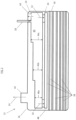
FIG. 2 is a schematic view of an embodiment of the present invention of a falling film evaporator for an HVAC system. - Shown in
FIG. 1 is a schematic view an embodiment of a heating, ventilation and air conditioning (HVAC) unit, for example, a chiller 10 utilizing a fallingfilm evaporator 12 according to claim 1. - A flow of
vapor refrigerant 14 is directed into a compressor 16 and then to a condenser 18 that outputs a flow of liquid refrigerant 20 to an expansion valve 22. The expansion valve 22 outputs a vapor and liquid refrigerant mixture 24 toward theevaporator 12. Theevaporator 12 includes a plurality ofevaporator tubes 38 located therein, through which a heat transfer fluid 44 is circulated. The heat transfer fluid 44 is cooled via thermal energy transfer with the flow of refrigerant at theevaporator 12. - Referring now to
FIG. 2 , as stated above, theevaporator 12 according to claim 1 is a falling film evaporator. Theevaporator 12 includes anevaporator vessel 26 in which a refrigerant distribution system of theevaporator 12 is located. The distribution system includes adistributor 34 and avapor liquid separator 30, as well as other components. Aninlet port 28 extends through theevaporator vessel 26 to admit the vapor and liquid refrigerant mixture 24 into theevaporator 12. The vapor and liquid refrigerant mixture 24 is directed from theinlet port 28 into the vapor-liquid separator 30 in whichliquid refrigerant 32 is separated from the vapor and liquid refrigerant mixture 24. Theliquid refrigerant 32 is flowed from the vapor-liquid separator 30 into thedistributor 34, while vapor refrigerant 14 exits the vapor-liquid separator 30 through avapor vent 40 and flows toward asuction port 42 extending through theevaporator vessel 26 which directs thevapor refrigerant 14 toward the compressor 16. - The
distributor 34 is located above theevaporator tubes 38 to distribute the liquid refrigerant 32 over theevaporator tubes 38 via one or more distributor ports (not shown). A thermal energy exchange occurs between a flow of heat transfer medium 44 (shown inFIG. 1 ) flowing through theevaporator tubes 38 into and out of theevaporator 12 and theliquid refrigerant 32. As theliquid refrigerant 32 is boiled off in theevaporator 12, the resultingvapor refrigerant 14 is directed to the compressor 16 via thesuction port 42. While theevaporator 12 shown is rectangular in cross-section, one skilled in the art will appreciate that theevaporator 12 may be a variety of shapes, including spherical, cylindrical, rectilinear or any combination of shapes such as these. - The highest vapor velocities in an
evaporator 12 occur near thesuction port 42 where thevapor refrigerant 14 exits theevaporator vessel 26. The relatively high velocities in this region make it especially prone to pressure and efficiency loss. This is especially challenging in a falling film evaporator, in which refrigerant distribution systems occupy space near the top of the heat exchanger and relatively close to thesuction port 42. - To optimize the efficiency, cost, and physical space of the
evaporator 12, the height of the vapor-liquid separator 30 is varied along the length of theevaporator vessel 26. In the vicinity of thesuction port 42, a vapor-liquid separator height 46 is reduced, providing an increased space between the vapor-liquid separator 30 and thesuction port 42 for vapor refrigerant flow. Conversely, the vapor-liquid separator height 46 is increased at locations further from thesuction port 42 area where vapor refrigerant flow velocities are lower and efficiency impacts are less critical. The larger cross section of the vapor-liquid separator 30 in the regions further from thesuction port 42 improves vapor-liquid separation and refrigerant distribution functionality than would be possible with asmaller evaporator 12. The net effect of the configuration is that theevaporator 12 can have a more compact diameter and lower cost for a given efficiency and cooling capacity. - In some embodiments, such as shown in
FIG. 2 , thesuction port 42 is located at a firstlongitudinal end 48 of theevaporator 12. As such, the vapor-liquid separator height 46 is at a minimum at the firstlongitudinal end 48, or at thesuction port 42. In some embodiments, the vapor-liquid separator height 46 is at a maximum at a secondlongitudinal end 50, opposite the firstlongitudinal end 48. In the embodiment ofFIG. 2 the vapor-liquid separator height 46 is stepped, with a first separator height 46a at the firstlongitudinal end 48, asecond separator height 46b greater than the first separator height 46a, and athird separator height 46c greater than thesecond separator height 46b at the secondlongitudinal end 50. While three separator heights 46a-46c are shown in the embodiment ofFIG. 2 , one skilled in the art will readily appreciate that other quantities of separator heights may be utilized in other embodiments. - In some embodiments the
suction port 42 is not located at either of the firstlongitudinal end 48 or the secondlongitudinal end 50, but between the firstlongitudinal end 48 and the secondlongitudinal end 50. For example, in some embodiments thesuction port 42 is located midway between the firstlongitudinal end 48 and the secondlongitudinal end 50. In such embodiments, the vapor-liquid separator height 46 is at a minimum at thesuction port 42 and increases with increasing distance from thesuction port 42 toward either or both of the firstlongitudinal end 48 and the secondlongitudinal end 50. In some embodiments, the vapor-liquid separator height 46 is at a maximum at either or both of the firstlongitudinal end 48 and the secondlongitudinal end 50. - While the present disclosure has been described in detail in connection with only a limited number of embodiments, it should be readily understood that the present disclosure is not limited to such disclosed embodiments. Accordingly, the present disclosure is not to be seen as limited by the foregoing description, but is only limited by the scope of the appended claims.
Claims (11)
- A falling film evaporator comprising:an evaporator vessel (26);a plurality of evaporator tubes (38) disposed in the evaporator vessel through which a volume of thermal energy transfer medium is flowed;a suction port (42) extending through the evaporator vessel to remove vapor refrigerant (14) from the evaporator vessel (26); anda refrigerant distribution system (30, 34) disposed in the evaporator vessel to distribute a flow of liquid refrigerant (32) over the plurality of evaporator tubes (38), the refrigerant distribution system including:a distributor (34) disposed in the evaporator vessel (26) above the plurality of evaporator tubes (38) to distribute a flow of liquid refrigerant (32) over the plurality of evaporator tubes (38), anda vapor-liquid separator (30) disposed in the evaporator vessel (26) to separate the vapor refrigerant (14) from a vapor and liquid refrigerant mixture,characterised in that the vapor-liquid separator (30) is configured such that the vapor-liquid separator (30) has a first height (46a) at the suction port (42) and a second height (46b, 46c) greater than the first height at a longitudinal location other than at the suction port,and in that the first height (46a) transitions to the second height (46b, 46c) via a plurality of vertical steps.
- The falling film evaporator of claim 1, wherein the first height (46a) is a minimum height of the refrigerant distribution system (30, 34).
- The falling film evaporator of claim 1 or 2, wherein the suction port (42) is located at a first longitudinal end (48) of the evaporator vessel (26).
- The falling film evaporator of claim 3, wherein the second height (46c) is located at a second longitudinal end (50) of the evaporator vessel (26) opposite the first longitudinal end (48).
- The falling film evaporator of any of claims 1-4, wherein the suction port (42) is located between a first longitudinal end (48) of the evaporator vessel (26) and a second longitudinal end (50) of the evaporator vessel (26) and the first height (46a) is a minimum vapor-liquid separator (30) height.
- The falling film evaporator of claim 5, wherein the second height (46c) is at one or more of the first longitudinal end (48) or the second longitudinal end (50) and is a maximum height of the refrigerant distribution system (30, 34).
- A heating, ventilation and air conditioning (HVAC) system comprising:a condenser (18) flowing a flow of refrigerant therethrough; anda falling film evaporator (12) as claimed in claim 1 in flow communication with the condenser.
- The HVAC system of claim 7, wherein the first height (46a) is a minimum height of the vapor-liquid separator (30).
- The HVAC system of claim 7 or 8, wherein the suction port (42) is located between a first longitudinal end (48) of the evaporator vessel (26) and a second longitudinal end (50) of the evaporator vessel (26) and the first height is a minimum vapor-liquid separator (30) height.
- The HVAC system of claim 9, wherein the second height is at one or more of the first longitudinal end (48) or the second longitudinal end (50).
- The HVAC system of claim 10, wherein the second height is a maximum height of the vapor-liquid separator (30).
Applications Claiming Priority (2)
| Application Number | Priority Date | Filing Date | Title |
|---|---|---|---|
| US201662380159P | 2016-08-26 | 2016-08-26 | |
| PCT/US2017/048566 WO2018039532A1 (en) | 2016-08-26 | 2017-08-25 | Refrigerant distributor for falling film evaporator |
Publications (2)
| Publication Number | Publication Date |
|---|---|
| EP3504490A1 EP3504490A1 (en) | 2019-07-03 |
| EP3504490B1 true EP3504490B1 (en) | 2024-12-11 |
Family
ID=59772820
Family Applications (1)
| Application Number | Title | Priority Date | Filing Date |
|---|---|---|---|
| EP17761756.0A Active EP3504490B1 (en) | 2016-08-26 | 2017-08-25 | Falling film evaporator |
Country Status (4)
| Country | Link |
|---|---|
| US (1) | US10969146B2 (en) |
| EP (1) | EP3504490B1 (en) |
| CN (1) | CN109642760B (en) |
| WO (1) | WO2018039532A1 (en) |
Families Citing this family (2)
| Publication number | Priority date | Publication date | Assignee | Title |
|---|---|---|---|---|
| US12593427B2 (en) * | 2021-10-27 | 2026-03-31 | Carrier Corporation | Enhanced channel configuration for heat exchanger to cool power electronics |
| US12066224B2 (en) * | 2022-06-03 | 2024-08-20 | Trane International Inc. | Evaporator charge management and method for controlling the same |
Citations (1)
| Publication number | Priority date | Publication date | Assignee | Title |
|---|---|---|---|---|
| US5704422A (en) * | 1995-05-19 | 1998-01-06 | Huntsman Specialty Chemicals Corporation | Shrouded heat exchanger |
Family Cites Families (24)
| Publication number | Priority date | Publication date | Assignee | Title |
|---|---|---|---|---|
| US472671A (en) | 1892-04-12 | Feed-water heater | ||
| US1636958A (en) | 1922-08-07 | 1927-07-26 | Babcock & Wilcox Co | Heat-transfer device |
| US1979751A (en) | 1933-11-29 | 1934-11-06 | Charles H Leach | Heat exchange apparatus |
| US2341319A (en) | 1941-10-31 | 1944-02-08 | Lummus Co | Heat exchanger |
| US4858681A (en) | 1983-03-28 | 1989-08-22 | Tui Industries | Shell and tube heat exchanger |
| JP2627381B2 (en) | 1992-03-13 | 1997-07-02 | 矢崎総業株式会社 | Absorption refrigerator |
| US5546761A (en) * | 1994-02-16 | 1996-08-20 | Nippondenso Co., Ltd. | Receiver-integrated refrigerant condenser |
| US5588596A (en) * | 1995-05-25 | 1996-12-31 | American Standard Inc. | Falling film evaporator with refrigerant distribution system |
| CN1139769A (en) | 1995-07-06 | 1997-01-08 | 李新 | Electric cooker automatic controller |
| US6167713B1 (en) | 1999-03-12 | 2001-01-02 | American Standard Inc. | Falling film evaporator having two-phase distribution system |
| KR100331985B1 (en) | 1999-09-15 | 2002-04-10 | 가나이 쓰도무 | Liquid distributor, falling film heat exchanger and absorption refrigerator |
| US6868695B1 (en) | 2004-04-13 | 2005-03-22 | American Standard International Inc. | Flow distributor and baffle system for a falling film evaporator |
| US8833437B2 (en) | 2009-05-06 | 2014-09-16 | Holtec International, Inc. | Heat exchanger apparatus for converting a shell-side liquid into a vapor |
| EP2457051A2 (en) | 2009-07-22 | 2012-05-30 | Johnson Controls Technology Company | Compact evaporator for chillers |
| US20110056664A1 (en) | 2009-09-08 | 2011-03-10 | Johnson Controls Technology Company | Vapor compression system |
| DE102013010510B4 (en) * | 2012-09-06 | 2015-02-19 | Gea Refrigeration Germany Gmbh | Flooded evaporator with integrated liquid separation |
| US9677818B2 (en) * | 2013-07-11 | 2017-06-13 | Daikin Applied Americas Inc. | Heat exchanger |
| US10302364B2 (en) * | 2013-09-06 | 2019-05-28 | Carrier Corporation | Integrated separator-distributor for falling film evaporator |
| CN103673694B (en) | 2013-12-05 | 2018-10-19 | 上海热泰能源技术有限公司 | Falling-film shell-and-plate heat exchanger |
| KR102204612B1 (en) * | 2013-12-17 | 2021-01-19 | 엘지전자 주식회사 | Distributor unit and evaporator comprising the same |
| CN103727707A (en) * | 2013-12-30 | 2014-04-16 | 麦克维尔空调制冷(武汉)有限公司 | Full-falling-film evaporator with double refrigerant distribution devices |
| FR3038037B1 (en) | 2015-06-29 | 2018-04-20 | Trane International Inc. | SUCTION DUCT AND DUAL SUCTION DUCT FOR AN IMMERSION EVAPORATOR |
| CN105157455A (en) | 2015-07-31 | 2015-12-16 | 华南理工大学 | Flow-area-variable backflow plate-fin heat exchanger and control method thereof |
| CN205403254U (en) * | 2016-02-18 | 2016-07-27 | 约克(无锡)空调冷冻设备有限公司 | Falling film evaporation ware suitable for pressure refrigerant |
-
2017
- 2017-08-25 WO PCT/US2017/048566 patent/WO2018039532A1/en not_active Ceased
- 2017-08-25 US US16/328,477 patent/US10969146B2/en active Active
- 2017-08-25 EP EP17761756.0A patent/EP3504490B1/en active Active
- 2017-08-25 CN CN201780052482.7A patent/CN109642760B/en active Active
Patent Citations (1)
| Publication number | Priority date | Publication date | Assignee | Title |
|---|---|---|---|---|
| US5704422A (en) * | 1995-05-19 | 1998-01-06 | Huntsman Specialty Chemicals Corporation | Shrouded heat exchanger |
Also Published As
| Publication number | Publication date |
|---|---|
| CN109642760A (en) | 2019-04-16 |
| WO2018039532A1 (en) | 2018-03-01 |
| US10969146B2 (en) | 2021-04-06 |
| EP3504490A1 (en) | 2019-07-03 |
| CN109642760B (en) | 2021-09-17 |
| US20190195541A1 (en) | 2019-06-27 |
Similar Documents
| Publication | Publication Date | Title |
|---|---|---|
| US11365912B2 (en) | Suction duct and multiple suction ducts inside a shell of a flooded evaporator | |
| JP6701372B2 (en) | Heat exchanger | |
| US10132537B1 (en) | Heat exchanger | |
| US9541314B2 (en) | Heat exchanger | |
| US20130277018A1 (en) | Heat exchanger | |
| CN113227698B (en) | heat exchanger | |
| US11029094B2 (en) | Heat exchanger | |
| EP3087335B1 (en) | Distributor for falling film evaporator | |
| CN104854410B (en) | low pressure cooler | |
| EP3042127B1 (en) | Integrated separator-distributor for falling film evaporator | |
| US10969146B2 (en) | Refrigerant distributor for falling film evaporator | |
| CN113195997B (en) | heat exchanger | |
| KR20150098141A (en) | Heat exchanger and air conditional having the same |
Legal Events
| Date | Code | Title | Description |
|---|---|---|---|
| STAA | Information on the status of an ep patent application or granted ep patent |
Free format text: STATUS: UNKNOWN |
|
| STAA | Information on the status of an ep patent application or granted ep patent |
Free format text: STATUS: THE INTERNATIONAL PUBLICATION HAS BEEN MADE |
|
| PUAI | Public reference made under article 153(3) epc to a published international application that has entered the european phase |
Free format text: ORIGINAL CODE: 0009012 |
|
| STAA | Information on the status of an ep patent application or granted ep patent |
Free format text: STATUS: REQUEST FOR EXAMINATION WAS MADE |
|
| 17P | Request for examination filed |
Effective date: 20190227 |
|
| AK | Designated contracting states |
Kind code of ref document: A1 Designated state(s): AL AT BE BG CH CY CZ DE DK EE ES FI FR GB GR HR HU IE IS IT LI LT LU LV MC MK MT NL NO PL PT RO RS SE SI SK SM TR |
|
| AX | Request for extension of the european patent |
Extension state: BA ME |
|
| DAV | Request for validation of the european patent (deleted) | ||
| DAX | Request for extension of the european patent (deleted) | ||
| STAA | Information on the status of an ep patent application or granted ep patent |
Free format text: STATUS: EXAMINATION IS IN PROGRESS |
|
| 17Q | First examination report despatched |
Effective date: 20210205 |
|
| P01 | Opt-out of the competence of the unified patent court (upc) registered |
Effective date: 20230527 |
|
| GRAP | Despatch of communication of intention to grant a patent |
Free format text: ORIGINAL CODE: EPIDOSNIGR1 |
|
| STAA | Information on the status of an ep patent application or granted ep patent |
Free format text: STATUS: GRANT OF PATENT IS INTENDED |
|
| RIC1 | Information provided on ipc code assigned before grant |
Ipc: F28D 7/16 20060101ALI20240126BHEP Ipc: F28F 9/02 20060101ALI20240126BHEP Ipc: F28D 21/00 20060101ALI20240126BHEP Ipc: F25B 39/02 20060101AFI20240126BHEP |
|
| INTG | Intention to grant announced |
Effective date: 20240228 |
|
| RAP3 | Party data changed (applicant data changed or rights of an application transferred) |
Owner name: CARRIER CORPORATION |
|
| GRAJ | Information related to disapproval of communication of intention to grant by the applicant or resumption of examination proceedings by the epo deleted |
Free format text: ORIGINAL CODE: EPIDOSDIGR1 |
|
| STAA | Information on the status of an ep patent application or granted ep patent |
Free format text: STATUS: EXAMINATION IS IN PROGRESS |
|
| GRAP | Despatch of communication of intention to grant a patent |
Free format text: ORIGINAL CODE: EPIDOSNIGR1 |
|
| STAA | Information on the status of an ep patent application or granted ep patent |
Free format text: STATUS: GRANT OF PATENT IS INTENDED |
|
| INTC | Intention to grant announced (deleted) | ||
| INTG | Intention to grant announced |
Effective date: 20240703 |
|
| GRAS | Grant fee paid |
Free format text: ORIGINAL CODE: EPIDOSNIGR3 |
|
| GRAA | (expected) grant |
Free format text: ORIGINAL CODE: 0009210 |
|
| STAA | Information on the status of an ep patent application or granted ep patent |
Free format text: STATUS: THE PATENT HAS BEEN GRANTED |
|
| AK | Designated contracting states |
Kind code of ref document: B1 Designated state(s): AL AT BE BG CH CY CZ DE DK EE ES FI FR GB GR HR HU IE IS IT LI LT LU LV MC MK MT NL NO PL PT RO RS SE SI SK SM TR |
|
| REG | Reference to a national code |
Ref country code: GB Ref legal event code: FG4D |
|
| REG | Reference to a national code |
Ref country code: CH Ref legal event code: EP |
|
| REG | Reference to a national code |
Ref country code: DE Ref legal event code: R096 Ref document number: 602017086702 Country of ref document: DE |
|
| REG | Reference to a national code |
Ref country code: IE Ref legal event code: FG4D |
|
| REG | Reference to a national code |
Ref country code: NL Ref legal event code: FP |
|
| REG | Reference to a national code |
Ref country code: LT Ref legal event code: MG9D |
|
| PG25 | Lapsed in a contracting state [announced via postgrant information from national office to epo] |
Ref country code: HR Free format text: LAPSE BECAUSE OF FAILURE TO SUBMIT A TRANSLATION OF THE DESCRIPTION OR TO PAY THE FEE WITHIN THE PRESCRIBED TIME-LIMIT Effective date: 20241211 |
|
| PG25 | Lapsed in a contracting state [announced via postgrant information from national office to epo] |
Ref country code: FI Free format text: LAPSE BECAUSE OF FAILURE TO SUBMIT A TRANSLATION OF THE DESCRIPTION OR TO PAY THE FEE WITHIN THE PRESCRIBED TIME-LIMIT Effective date: 20241211 |
|
| PG25 | Lapsed in a contracting state [announced via postgrant information from national office to epo] |
Ref country code: BG Free format text: LAPSE BECAUSE OF FAILURE TO SUBMIT A TRANSLATION OF THE DESCRIPTION OR TO PAY THE FEE WITHIN THE PRESCRIBED TIME-LIMIT Effective date: 20241211 |
|
| PG25 | Lapsed in a contracting state [announced via postgrant information from national office to epo] |
Ref country code: ES Free format text: LAPSE BECAUSE OF FAILURE TO SUBMIT A TRANSLATION OF THE DESCRIPTION OR TO PAY THE FEE WITHIN THE PRESCRIBED TIME-LIMIT Effective date: 20241211 |
|
| PG25 | Lapsed in a contracting state [announced via postgrant information from national office to epo] |
Ref country code: NO Free format text: LAPSE BECAUSE OF FAILURE TO SUBMIT A TRANSLATION OF THE DESCRIPTION OR TO PAY THE FEE WITHIN THE PRESCRIBED TIME-LIMIT Effective date: 20250311 |
|
| PG25 | Lapsed in a contracting state [announced via postgrant information from national office to epo] |
Ref country code: LV Free format text: LAPSE BECAUSE OF FAILURE TO SUBMIT A TRANSLATION OF THE DESCRIPTION OR TO PAY THE FEE WITHIN THE PRESCRIBED TIME-LIMIT Effective date: 20241211 Ref country code: GR Free format text: LAPSE BECAUSE OF FAILURE TO SUBMIT A TRANSLATION OF THE DESCRIPTION OR TO PAY THE FEE WITHIN THE PRESCRIBED TIME-LIMIT Effective date: 20250312 |
|
| PG25 | Lapsed in a contracting state [announced via postgrant information from national office to epo] |
Ref country code: RS Free format text: LAPSE BECAUSE OF FAILURE TO SUBMIT A TRANSLATION OF THE DESCRIPTION OR TO PAY THE FEE WITHIN THE PRESCRIBED TIME-LIMIT Effective date: 20250311 |
|
| REG | Reference to a national code |
Ref country code: AT Ref legal event code: MK05 Ref document number: 1750658 Country of ref document: AT Kind code of ref document: T Effective date: 20241211 |
|
| PG25 | Lapsed in a contracting state [announced via postgrant information from national office to epo] |
Ref country code: SM Free format text: LAPSE BECAUSE OF FAILURE TO SUBMIT A TRANSLATION OF THE DESCRIPTION OR TO PAY THE FEE WITHIN THE PRESCRIBED TIME-LIMIT Effective date: 20241211 |
|
| PG25 | Lapsed in a contracting state [announced via postgrant information from national office to epo] |
Ref country code: PL Free format text: LAPSE BECAUSE OF FAILURE TO SUBMIT A TRANSLATION OF THE DESCRIPTION OR TO PAY THE FEE WITHIN THE PRESCRIBED TIME-LIMIT Effective date: 20241211 |
|
| PG25 | Lapsed in a contracting state [announced via postgrant information from national office to epo] |
Ref country code: IS Free format text: LAPSE BECAUSE OF FAILURE TO SUBMIT A TRANSLATION OF THE DESCRIPTION OR TO PAY THE FEE WITHIN THE PRESCRIBED TIME-LIMIT Effective date: 20250411 |
|
| PG25 | Lapsed in a contracting state [announced via postgrant information from national office to epo] |
Ref country code: PT Free format text: LAPSE BECAUSE OF FAILURE TO SUBMIT A TRANSLATION OF THE DESCRIPTION OR TO PAY THE FEE WITHIN THE PRESCRIBED TIME-LIMIT Effective date: 20250411 |
|
| PG25 | Lapsed in a contracting state [announced via postgrant information from national office to epo] |
Ref country code: EE Free format text: LAPSE BECAUSE OF FAILURE TO SUBMIT A TRANSLATION OF THE DESCRIPTION OR TO PAY THE FEE WITHIN THE PRESCRIBED TIME-LIMIT Effective date: 20241211 |
|
| PG25 | Lapsed in a contracting state [announced via postgrant information from national office to epo] |
Ref country code: AT Free format text: LAPSE BECAUSE OF FAILURE TO SUBMIT A TRANSLATION OF THE DESCRIPTION OR TO PAY THE FEE WITHIN THE PRESCRIBED TIME-LIMIT Effective date: 20241211 Ref country code: RO Free format text: LAPSE BECAUSE OF FAILURE TO SUBMIT A TRANSLATION OF THE DESCRIPTION OR TO PAY THE FEE WITHIN THE PRESCRIBED TIME-LIMIT Effective date: 20241211 |
|
| PG25 | Lapsed in a contracting state [announced via postgrant information from national office to epo] |
Ref country code: SK Free format text: LAPSE BECAUSE OF FAILURE TO SUBMIT A TRANSLATION OF THE DESCRIPTION OR TO PAY THE FEE WITHIN THE PRESCRIBED TIME-LIMIT Effective date: 20241211 |
|
| PG25 | Lapsed in a contracting state [announced via postgrant information from national office to epo] |
Ref country code: CZ Free format text: LAPSE BECAUSE OF FAILURE TO SUBMIT A TRANSLATION OF THE DESCRIPTION OR TO PAY THE FEE WITHIN THE PRESCRIBED TIME-LIMIT Effective date: 20241211 |
|
| PG25 | Lapsed in a contracting state [announced via postgrant information from national office to epo] |
Ref country code: IT Free format text: LAPSE BECAUSE OF FAILURE TO SUBMIT A TRANSLATION OF THE DESCRIPTION OR TO PAY THE FEE WITHIN THE PRESCRIBED TIME-LIMIT Effective date: 20241211 |
|
| PG25 | Lapsed in a contracting state [announced via postgrant information from national office to epo] |
Ref country code: SE Free format text: LAPSE BECAUSE OF FAILURE TO SUBMIT A TRANSLATION OF THE DESCRIPTION OR TO PAY THE FEE WITHIN THE PRESCRIBED TIME-LIMIT Effective date: 20241211 |
|
| REG | Reference to a national code |
Ref country code: DE Ref legal event code: R097 Ref document number: 602017086702 Country of ref document: DE |
|
| PG25 | Lapsed in a contracting state [announced via postgrant information from national office to epo] |
Ref country code: DK Free format text: LAPSE BECAUSE OF FAILURE TO SUBMIT A TRANSLATION OF THE DESCRIPTION OR TO PAY THE FEE WITHIN THE PRESCRIBED TIME-LIMIT Effective date: 20241211 |
|
| PGFP | Annual fee paid to national office [announced via postgrant information from national office to epo] |
Ref country code: DE Payment date: 20250724 Year of fee payment: 9 |
|
| PGFP | Annual fee paid to national office [announced via postgrant information from national office to epo] |
Ref country code: GB Payment date: 20250724 Year of fee payment: 9 |
|
| PLBE | No opposition filed within time limit |
Free format text: ORIGINAL CODE: 0009261 |
|
| STAA | Information on the status of an ep patent application or granted ep patent |
Free format text: STATUS: NO OPPOSITION FILED WITHIN TIME LIMIT |
|
| PGFP | Annual fee paid to national office [announced via postgrant information from national office to epo] |
Ref country code: FR Payment date: 20250725 Year of fee payment: 9 |
|
| REG | Reference to a national code |
Ref country code: CH Ref legal event code: L10 Free format text: ST27 STATUS EVENT CODE: U-0-0-L10-L00 (AS PROVIDED BY THE NATIONAL OFFICE) Effective date: 20251022 |
|
| 26N | No opposition filed |
Effective date: 20250912 |
|
| REG | Reference to a national code |
Ref country code: CH Ref legal event code: H13 Free format text: ST27 STATUS EVENT CODE: U-0-0-H10-H13 (AS PROVIDED BY THE NATIONAL OFFICE) Effective date: 20260324 |
|
| PG25 | Lapsed in a contracting state [announced via postgrant information from national office to epo] |
Ref country code: MC Free format text: LAPSE BECAUSE OF FAILURE TO SUBMIT A TRANSLATION OF THE DESCRIPTION OR TO PAY THE FEE WITHIN THE PRESCRIBED TIME-LIMIT Effective date: 20241211 |
|
| REG | Reference to a national code |
Ref country code: NL Ref legal event code: MM Effective date: 20250901 |
|
| PG25 | Lapsed in a contracting state [announced via postgrant information from national office to epo] |
Ref country code: LU Free format text: LAPSE BECAUSE OF NON-PAYMENT OF DUE FEES Effective date: 20250825 |
|
| PG25 | Lapsed in a contracting state [announced via postgrant information from national office to epo] |
Ref country code: CH Free format text: LAPSE BECAUSE OF NON-PAYMENT OF DUE FEES Effective date: 20250831 |