EP3504418B1 - Variable geometry thruster - Google Patents
Variable geometry thruster Download PDFInfo
- Publication number
- EP3504418B1 EP3504418B1 EP17844440.2A EP17844440A EP3504418B1 EP 3504418 B1 EP3504418 B1 EP 3504418B1 EP 17844440 A EP17844440 A EP 17844440A EP 3504418 B1 EP3504418 B1 EP 3504418B1
- Authority
- EP
- European Patent Office
- Prior art keywords
- vehicle
- diffusing structure
- primary fluid
- passage
- constricting element
- Prior art date
- Legal status (The legal status is an assumption and is not a legal conclusion. Google has not performed a legal analysis and makes no representation as to the accuracy of the status listed.)
- Active
Links
Images


Classifications
-
- B—PERFORMING OPERATIONS; TRANSPORTING
- B64—AIRCRAFT; AVIATION; COSMONAUTICS
- B64C—AEROPLANES; HELICOPTERS
- B64C15/00—Attitude, flight direction, or altitude control by jet reaction
- B64C15/14—Attitude, flight direction, or altitude control by jet reaction the jets being other than main propulsion jets
-
- F—MECHANICAL ENGINEERING; LIGHTING; HEATING; WEAPONS; BLASTING
- F15—FLUID-PRESSURE ACTUATORS; HYDRAULICS OR PNEUMATICS IN GENERAL
- F15D—FLUID DYNAMICS, i.e. METHODS OR MEANS FOR INFLUENCING THE FLOW OF GASES OR LIQUIDS
- F15D1/00—Influencing flow of fluids
- F15D1/08—Influencing flow of fluids of jets leaving an orifice
-
- B—PERFORMING OPERATIONS; TRANSPORTING
- B60—VEHICLES IN GENERAL
- B60F—VEHICLES FOR USE BOTH ON RAIL AND ON ROAD; VEHICLES CAPABLE OF TRAVELLING IN OR ON DIFFERENT MEDIA, e.g. AMPHIBIOUS VEHICLES
- B60F5/00—Other vehicles capable of travelling in or on different media
- B60F5/02—Other vehicles capable of travelling in or on different media convertible into aircraft
-
- B—PERFORMING OPERATIONS; TRANSPORTING
- B64—AIRCRAFT; AVIATION; COSMONAUTICS
- B64C—AEROPLANES; HELICOPTERS
- B64C29/00—Aircraft capable of landing or taking-off vertically, e.g. vertical take-off and landing [VTOL] aircraft
- B64C29/02—Aircraft capable of landing or taking-off vertically, e.g. vertical take-off and landing [VTOL] aircraft having its flight directional axis vertical when grounded
- B64C29/04—Aircraft capable of landing or taking-off vertically, e.g. vertical take-off and landing [VTOL] aircraft having its flight directional axis vertical when grounded characterised by jet-reaction propulsion
-
- F—MECHANICAL ENGINEERING; LIGHTING; HEATING; WEAPONS; BLASTING
- F02—COMBUSTION ENGINES; HOT-GAS OR COMBUSTION-PRODUCT ENGINE PLANTS
- F02C—GAS-TURBINE PLANTS; AIR INTAKES FOR JET-PROPULSION PLANTS; CONTROLLING FUEL SUPPLY IN AIR-BREATHING JET-PROPULSION PLANTS
- F02C6/00—Plural gas-turbine plants; Combinations of gas-turbine plants with other apparatus; Adaptations of gas-turbine plants for special use
- F02C6/04—Gas-turbine plants providing heated or pressurised working fluid for other apparatus, e.g. without mechanical power output
- F02C6/06—Gas-turbine plants providing heated or pressurised working fluid for other apparatus, e.g. without mechanical power output providing compressed gas
- F02C6/08—Gas-turbine plants providing heated or pressurised working fluid for other apparatus, e.g. without mechanical power output providing compressed gas the gas being bled from the gas-turbine compressor
-
- F—MECHANICAL ENGINEERING; LIGHTING; HEATING; WEAPONS; BLASTING
- F02—COMBUSTION ENGINES; HOT-GAS OR COMBUSTION-PRODUCT ENGINE PLANTS
- F02K—JET-PROPULSION PLANTS
- F02K1/00—Plants characterised by the form or arrangement of the jet pipe or nozzle; Jet pipes or nozzles peculiar thereto
- F02K1/28—Plants characterised by the form or arrangement of the jet pipe or nozzle; Jet pipes or nozzles peculiar thereto using fluid jets to influence the jet flow
-
- F—MECHANICAL ENGINEERING; LIGHTING; HEATING; WEAPONS; BLASTING
- F02—COMBUSTION ENGINES; HOT-GAS OR COMBUSTION-PRODUCT ENGINE PLANTS
- F02K—JET-PROPULSION PLANTS
- F02K1/00—Plants characterised by the form or arrangement of the jet pipe or nozzle; Jet pipes or nozzles peculiar thereto
- F02K1/38—Introducing air inside the jet
- F02K1/386—Introducing air inside the jet mixing devices in the jet pipe, e.g. for mixing primary and secondary flow
-
- F—MECHANICAL ENGINEERING; LIGHTING; HEATING; WEAPONS; BLASTING
- F15—FLUID-PRESSURE ACTUATORS; HYDRAULICS OR PNEUMATICS IN GENERAL
- F15D—FLUID DYNAMICS, i.e. METHODS OR MEANS FOR INFLUENCING THE FLOW OF GASES OR LIQUIDS
- F15D1/00—Influencing flow of fluids
- F15D1/002—Influencing flow of fluids by influencing the boundary layer
- F15D1/0065—Influencing flow of fluids by influencing the boundary layer using active means, e.g. supplying external energy or injecting fluid
- F15D1/007—Influencing flow of fluids by influencing the boundary layer using active means, e.g. supplying external energy or injecting fluid comprising surfaces being moved by external supplied energy
-
- F—MECHANICAL ENGINEERING; LIGHTING; HEATING; WEAPONS; BLASTING
- F15—FLUID-PRESSURE ACTUATORS; HYDRAULICS OR PNEUMATICS IN GENERAL
- F15D—FLUID DYNAMICS, i.e. METHODS OR MEANS FOR INFLUENCING THE FLOW OF GASES OR LIQUIDS
- F15D1/00—Influencing flow of fluids
- F15D1/002—Influencing flow of fluids by influencing the boundary layer
- F15D1/0065—Influencing flow of fluids by influencing the boundary layer using active means, e.g. supplying external energy or injecting fluid
- F15D1/008—Influencing flow of fluids by influencing the boundary layer using active means, e.g. supplying external energy or injecting fluid comprising fluid injection or suction means
-
- F—MECHANICAL ENGINEERING; LIGHTING; HEATING; WEAPONS; BLASTING
- F02—COMBUSTION ENGINES; HOT-GAS OR COMBUSTION-PRODUCT ENGINE PLANTS
- F02K—JET-PROPULSION PLANTS
- F02K3/00—Plants including a gas turbine driving a compressor or a ducted fan
- F02K3/02—Plants including a gas turbine driving a compressor or a ducted fan in which part of the working fluid by-passes the turbine and combustion chamber
- F02K3/04—Plants including a gas turbine driving a compressor or a ducted fan in which part of the working fluid by-passes the turbine and combustion chamber the plant including ducted fans, i.e. fans with high volume, low pressure outputs, for augmenting the jet thrust, e.g. of double-flow type
-
- F—MECHANICAL ENGINEERING; LIGHTING; HEATING; WEAPONS; BLASTING
- F05—INDEXING SCHEMES RELATING TO ENGINES OR PUMPS IN VARIOUS SUBCLASSES OF CLASSES F01-F04
- F05D—INDEXING SCHEME FOR ASPECTS RELATING TO NON-POSITIVE-DISPLACEMENT MACHINES OR ENGINES, GAS-TURBINES OR JET-PROPULSION PLANTS
- F05D2220/00—Application
- F05D2220/30—Application in turbines
- F05D2220/32—Application in turbines in gas turbines
- F05D2220/323—Application in turbines in gas turbines for aircraft propulsion, e.g. jet engines
-
- F—MECHANICAL ENGINEERING; LIGHTING; HEATING; WEAPONS; BLASTING
- F05—INDEXING SCHEMES RELATING TO ENGINES OR PUMPS IN VARIOUS SUBCLASSES OF CLASSES F01-F04
- F05D—INDEXING SCHEME FOR ASPECTS RELATING TO NON-POSITIVE-DISPLACEMENT MACHINES OR ENGINES, GAS-TURBINES OR JET-PROPULSION PLANTS
- F05D2240/00—Components
- F05D2240/10—Stators
-
- F—MECHANICAL ENGINEERING; LIGHTING; HEATING; WEAPONS; BLASTING
- F05—INDEXING SCHEMES RELATING TO ENGINES OR PUMPS IN VARIOUS SUBCLASSES OF CLASSES F01-F04
- F05D—INDEXING SCHEME FOR ASPECTS RELATING TO NON-POSITIVE-DISPLACEMENT MACHINES OR ENGINES, GAS-TURBINES OR JET-PROPULSION PLANTS
- F05D2260/00—Function
- F05D2260/60—Fluid transfer
- F05D2260/606—Bypassing the fluid
-
- F—MECHANICAL ENGINEERING; LIGHTING; HEATING; WEAPONS; BLASTING
- F05—INDEXING SCHEMES RELATING TO ENGINES OR PUMPS IN VARIOUS SUBCLASSES OF CLASSES F01-F04
- F05D—INDEXING SCHEME FOR ASPECTS RELATING TO NON-POSITIVE-DISPLACEMENT MACHINES OR ENGINES, GAS-TURBINES OR JET-PROPULSION PLANTS
- F05D2270/00—Control
- F05D2270/01—Purpose of the control system
- F05D2270/17—Purpose of the control system to control boundary layer
- F05D2270/173—Purpose of the control system to control boundary layer by the Coanda effect
Definitions
- the velocity measured behind the round ends of the thruster at about one length of the ejector downstream of its exit plane remained in excess of 321.8 km/h (200 mph), whereas in the middle of the thruster corresponding to the straight or linear geometry, the velocity dropped to less than 160.9 km/h (100 mph).
- Document US5996936 discloses an exhaust nozzle for a gas turbine engine including a converging inlet duct disposed in flow communication with a diverging outlet duct at a throat there-between.
- Document US3370794 discloses a system for controlling the trajectory of rocket vehicles, using hot gas valves for modulating the flow of propellant mixture into the divergent zone of the engine.
- FIG. 1 illustrates a cross-sectional portion of a fixed-geometry Coanda-type thruster 100 including diffusing structure 110.
- a conduit portion such as primary fluid area plenum 120, is fixed in its geometrical configuration, making the local conditions of the primary fluid provided by the plenum and the entrainment of secondary fluid introduced via an intake structure 130 perhaps entirely dependent on the conditions of primary fluid delivery - pressures, flow rates and temperatures, for example.
- the performance of the thruster 100 depends on the upstream supply of the primary fluid and may have limited high efficiency at conditions matching the best entrainment and minimal losses.
- Thruster 100 includes a fixed shim 140 without fringes. Such a geometry may allow ideal performance at a given flow condition or mass flow rate, pressure and temperature combination of the primary fluid.
- An embodiment includes a Coanda thruster that can change its primary fluid introduction conditions to match the flow conditions, thereby performing more efficiently and generating higher entrainment at conditions different from the ideal conditions described with regard to FIG 1 .
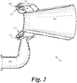
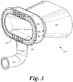
- FIG. 2 illustrates in cross-section
- FIG. 3 illustrates in side perspective view, a Coanda-type thruster 200 according to an embodiment and similar to thruster 100 illustrated in FIG. 1 .
- Thruster 200 includes a diffusing structure 210 and a conduit portion, such as primary fluid area plenum 220.
- Plenum 220 supplies primary fluid
- an intake structure 230 provides secondary fluid, such as ambient air, to the diffusing structure 210 for mixing of the primary and secondary fluids therein.
- the diffusing structure 210 comprises a terminal end configured to provide egress from the thruster 200 for the mixed primary and secondary fluids. More particularly, and in an embodiment, plenum 220 introduces the primary fluid to a convex Coanda surface 215.
- the primary fluid may consist of, for non-limiting example, compressor bleed air from a turbojet or pressurized exhaust gas from a gas generator delivered to plenum 220 via a primary-fluid source, such as a duct 250.
- Thruster 200 further includes a flow controller 240 discussed in greater detail below herein.
- plenum 220 introduces the primary fluid to the diffusing structure 210 through a series of passages 450.
- Each passage 450 is defined at least in part by a respective wall portion 460.
- Flow controller 240 includes a series of constricting elements, such as shims 440, disposed adjacent or face to face to a corresponding one of the wall portions 460.
- the shims 440 are manufactured out of a metal material flexible enough and thin enough to withstand multiple cycles of the operation.
- Flow controller 240 further includes an actuating apparatus coupled to the shims 440.
- the actuating apparatus is configured to urge the shims 440 toward their corresponding wall portion 460, thereby reducing the cross-sectional area of each associated passage 450. Additionally, the actuating apparatus may be configured to actively withdraw the shims 440 away from their corresponding wall portion 460, thereby increasing the cross-sectional area of each associated passage 450.
- the actuating apparatus includes a primary lever 400 coupled to a series of secondary levers 410, each of which is coupled to a corresponding bushing 420.
- Each bushing 420 is, in turn, coupled to a corresponding threaded pin 430 engaged with threaded slots formed in the intake structure 230.
- a tip of each pin 430 abuts a corresponding one of the shims 440 so as to enable deflection of the shims toward their corresponding wall portion 460.
- passage 450 is at its maximum cross-sectional area and flow of the primary fluid therethrough into diffusing structure 210 is minimally constricted.
- the local increase in velocity decreases the static pressure per Bernoulli's principle, allowing more air to be entrained from the ambient and resulting in a larger mass flow compared to the fixed-geometry thruster at similar conditions of primary mass flow rate, pressure and temperature.
- a turbine gas generator producing 1 kg/sec of combustion gas at a temperature of 726.85 °C (1000 K) and 200 kPa (2 bar) pressure at 100,000 RPM and supplying a thruster-ejector designed for these conditions with the primary fluid produces 667.23 N (150 lbf) of thrust.
- the same gas generator working at 85,000 RPM speed produces only 0.75 kg/s of combustion gas at 676.85 °C (950 K) and 140 kPa (1.4 bar) and the performance of the fixed geometry primary fluid passage determines a drop in thrust to 444.8 N (100 lbf).
- the main reason for it is the reduction of the emerging velocity of the primary fluid into the entrainment area, determining a higher local static pressure and therefore less entrainment happens.
- the changing (reduction) of the primary area to determine a higher local primary fluid emerging velocity, and according to Bernoulli principle a lower static pressure, increases significantly the entrainment ratio and the thrust to 533.78 N (120 lbf), mainly due to an increase of 20% in the entrained air.
- ⁇ is the mass flow rate of the primary fluid
- y is the specific heat coefficient
- Ru is the universal gas constant
- T is the temperature
- P are pressures coresponding to the ambient and the total pressure of the flow.
- the shims 440 may be manufactured out of stainless steel or any other material that can withstand high temperatures of up to 954.44 °C (1750 F) and still retain elasticity and a life of at least 2000 cycles.
- the mechanism of moving the pins 430 to reduce the passage 450 area and optimize the flow may be mechanical in character. However, other actuation mechanisms could be employed.
- a manifold (not shown) may be employed to provide compressed air from a source, such as a compressor or any other high pressure source, to actuate the pins 430 to urge the shims 440 into the flow.
- electric or magnetic actuators (not shown) could be used to perform the same function.
- a mechanism that contains linear and semicircular actuators (not shown) is employed to enable the change in geometry of various segments or slot blocks of the thruster, adapting it to the conditions at hand.
- the deflection of shims 440 may be such that the mechanism completely blocks the flow into all passages, shutting off the flow and cancelling thrust generation at various stages of the flight of a vehicle.
- the preferential shutting off of portions of the primary slots is employed to generate a vectored thrust to reduce the landing distance of an flying vehicle.
- the thruster is used to balance a tailsitter in a symmetrical deployment ( i.e., two or more thrusters on the plane or aerial vehicle) and the actuation of the shims 440 allows attitude control of the aircraft in hovering or take off or landing.
- a flying car hover is enhanced by employing the variable geometry feature of the thrusters to control its attitude/speed and can be used for landing or take off or level flight.
- thruster 200 can be integrated into the induction track between an air filter and a throttle-body/carburetor, and upstream of a cylinder or combustion chamber, associated with an internal combustion engine.
- thruster 200 could be placed in an exhaust pipe downstream of the combustion chamber of an internal combustion engine.
Landscapes
- Engineering & Computer Science (AREA)
- Mechanical Engineering (AREA)
- Chemical & Material Sciences (AREA)
- Combustion & Propulsion (AREA)
- General Engineering & Computer Science (AREA)
- Aviation & Aerospace Engineering (AREA)
- Physics & Mathematics (AREA)
- Fluid Mechanics (AREA)
- Transportation (AREA)
- Jet Pumps And Other Pumps (AREA)
- Structures Of Non-Positive Displacement Pumps (AREA)
- Organic Low-Molecular-Weight Compounds And Preparation Thereof (AREA)
Description
- This disclosure is protected under United States and International Copyright Laws. © 2017 Jetoptera. All rights reserved. A portion of the disclosure of this patent document contains material which is subject to copyright protection. The copyright owner has no objection to the facsimile reproduction by anyone of the patent document or the patent disclosure, as it appears in the Patent and Trademark Office patent file or records, but otherwise reserves all copyrights whatsoever.
- This application claims priority to
U.S. Provisional Application No. 62/379,711, filed August 25, 2016 U.S. Provisional Application No. 62/380,108, filed August 26, 2016 - It has been demonstrated in tests that conditions in which there is less than optimal primary fluid flow supplied to an ejector/thruster, the operation in the round ends of the thruster or ejector remains very performant. However, the straight portion of the thruster is where the primary fluid injectors suffer a rapid performance degradation. Tests show that the efficiency of the thruster declined significantly with lower flow, yet measurements of the velocity of the mixed entrained/primary fluids efflux from the two ends of the thruster remain high even at low flows. In one test the velocity measured behind the round ends of the thruster at about one length of the ejector downstream of its exit plane remained in excess of 321.8 km/h (200 mph), whereas in the middle of the thruster corresponding to the straight or linear geometry, the velocity dropped to less than 160.9 km/h (100 mph).
- This is due to the specific flow pattern and the configuration of the rounded ends of the thruster in addition to the relative orientation of the emerging primary wall jets at non-parallel angles, facilitating the rapid entrainment and mixing with the ambient air, whereas the wall jets originating from the linear portion are parallel to each other and less efficient at lower flows.
- Document
US5996936 discloses an exhaust nozzle for a gas turbine engine including a converging inlet duct disposed in flow communication with a diverging outlet duct at a throat there-between. DocumentUS3370794 discloses a system for controlling the trajectory of rocket vehicles, using hot gas valves for modulating the flow of propellant mixture into the divergent zone of the engine. - It is an object of the present invention to provide a propulsion system according to claim 1 and a vehicle according to claim 8, comprising said propulsion system. Further developments are provided in dependent claims 2-7 and 9-12.
-
-
FIG. 1 illustrates a cross-sectional portion of a fixed-geometry thruster according to an embodiment; -
FIG. 2 illustrates a cross-sectional portion of a variable-geometry thruster according to an embodiment; -
FIG. 3 illustrates a side perspective view of a variable-geometry thruster according to an embodiment; -
FIG. 4 illustrates a side perspective view of variable-geometry components according to an embodiment; -
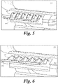
FIG. 5 illustrates a side perspective view of the variable-geometry components in fully open state according to an embodiment; -
FIG. 6 illustrates a side perspective view of the variable-geometry components in constricting state according to an embodiment; and -
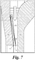
FIG. 7 illustrates a side cross-sectional view of variable-geometry components and a primary fluid passage according to an embodiment. - This patent application is intended to describe one or more embodiments of the present invention. It is to be understood that the use of absolute terms, such as "must," "will," and the like, as well as specific quantities, is to be construed as being applicable to one or more of such embodiments, but not necessarily to all such embodiments. As such, embodiments of the invention may omit, or include a modification of, one or more features or functionalities described in the context of such absolute terms.
-
FIG. 1 illustrates a cross-sectional portion of a fixed-geometry Coanda-type thruster 100 including diffusingstructure 110. A conduit portion, such as primaryfluid area plenum 120, is fixed in its geometrical configuration, making the local conditions of the primary fluid provided by the plenum and the entrainment of secondary fluid introduced via anintake structure 130 perhaps entirely dependent on the conditions of primary fluid delivery - pressures, flow rates and temperatures, for example. The performance of thethruster 100 depends on the upstream supply of the primary fluid and may have limited high efficiency at conditions matching the best entrainment and minimal losses.Thruster 100 includes afixed shim 140 without fringes. Such a geometry may allow ideal performance at a given flow condition or mass flow rate, pressure and temperature combination of the primary fluid. - An embodiment includes a Coanda thruster that can change its primary fluid introduction conditions to match the flow conditions, thereby performing more efficiently and generating higher entrainment at conditions different from the ideal conditions described with regard to
FIG 1 . - Specifically,
FIG. 2 illustrates in cross-section, andFIG. 3 illustrates in side perspective view, a Coanda-type thruster 200 according to an embodiment and similar tothruster 100 illustrated inFIG. 1 .Thruster 200 includes a diffusingstructure 210 and a conduit portion, such as primaryfluid area plenum 220. Plenum 220 supplies primary fluid, and anintake structure 230 provides secondary fluid, such as ambient air, to thediffusing structure 210 for mixing of the primary and secondary fluids therein. The diffusingstructure 210 comprises a terminal end configured to provide egress from thethruster 200 for the mixed primary and secondary fluids. More particularly, and in an embodiment,plenum 220 introduces the primary fluid to a convex Coandasurface 215. The primary fluid may consist of, for non-limiting example, compressor bleed air from a turbojet or pressurized exhaust gas from a gas generator delivered to plenum 220 via a primary-fluid source, such as aduct 250.Thruster 200 further includes aflow controller 240 discussed in greater detail below herein. - Referring now to
FIG. 4 , and in an embodiment,plenum 220 introduces the primary fluid to thediffusing structure 210 through a series ofpassages 450. Eachpassage 450 is defined at least in part by arespective wall portion 460.Flow controller 240 includes a series of constricting elements, such asshims 440, disposed adjacent or face to face to a corresponding one of thewall portions 460. Theshims 440 are manufactured out of a metal material flexible enough and thin enough to withstand multiple cycles of the operation. -
Flow controller 240 further includes an actuating apparatus coupled to theshims 440. The actuating apparatus is configured to urge theshims 440 toward theircorresponding wall portion 460, thereby reducing the cross-sectional area of each associatedpassage 450. Additionally, the actuating apparatus may be configured to actively withdraw theshims 440 away from theircorresponding wall portion 460, thereby increasing the cross-sectional area of each associatedpassage 450. - In the embodiment illustrated in
FIG. 4 , the actuating apparatus includes aprimary lever 400 coupled to a series ofsecondary levers 410, each of which is coupled to acorresponding bushing 420. Eachbushing 420 is, in turn, coupled to a corresponding threadedpin 430 engaged with threaded slots formed in theintake structure 230. A tip of eachpin 430 abuts a corresponding one of theshims 440 so as to enable deflection of the shims toward theircorresponding wall portion 460. - As shown in
FIG. 5 , when the actuating apparatus is in a fully open state,shims 440 have not been deflected bypins 430 towardwall portions 460 and are atposition 700 as illustrated inFIG. 7 . Consequently,passage 450 is at its maximum cross-sectional area and flow of the primary fluid therethrough into diffusingstructure 210 is minimally constricted. - As shown in
FIG. 6 , when a force generator (not shown) applies a predetermined motive force toprimary lever 400 moving the primary lever horizontally a corresponding predetermined distance, torque is applied to each of thesecondary levers 410. In response to this applied torque,secondary levers 410 rotate, thereby causing translational movement of the tips ofpins 430 towardwall portions 460. In turn,shims 440 are deflected bypins 430 towardwall portions 460 and are atposition 710 as illustrated inFIG. 7 . Consequently, the cross-sectional area ofpassage 450 is decreased and flow of the primary fluid therethrough into diffusingstructure 210 is constricted, and thusly accelerated, to a predetermined degree. Additionally, the injection velocity of the primary fluid at the wall jet emergence into theejector 200, which controls the Coanda effect and the entrainment ratio, increases, and high performance is maintained even at lower flow rates. - The local increase in velocity decreases the static pressure per Bernoulli's principle, allowing more air to be entrained from the ambient and resulting in a larger mass flow compared to the fixed-geometry thruster at similar conditions of primary mass flow rate, pressure and temperature.
- For instance, a turbine gas generator producing 1 kg/sec of combustion gas at a temperature of 726.85 °C (1000 K) and 200 kPa (2 bar) pressure at 100,000 RPM and supplying a thruster-ejector designed for these conditions with the primary fluid produces 667.23 N (150 lbf) of thrust. However, the same gas generator working at 85,000 RPM speed produces only 0.75 kg/s of combustion gas at 676.85 °C (950 K) and 140 kPa (1.4 bar) and the performance of the fixed geometry primary fluid passage determines a drop in thrust to 444.8 N (100 lbf).
- The main reason for it is the reduction of the emerging velocity of the primary fluid into the entrainment area, determining a higher local static pressure and therefore less entrainment happens. The changing (reduction) of the primary area to determine a higher local primary fluid emerging velocity, and according to Bernoulli principle a lower static pressure, increases significantly the entrainment ratio and the thrust to 533.78 N (120 lbf), mainly due to an increase of 20% in the entrained air.
- For those familiar with the subject, the isentropic expansion of the primary fluid jet results in the ideal thrust value of:

- Where Ẇ is the mass flow rate of the primary fluid, y is the specific heat coefficient, Ru is the universal gas constant and T is the temperature, while P are pressures coresponding to the ambient and the total pressure of the flow. By augmentation ratio, we refer to the ratio between the measured thrust and the formula above, calculated for the respective parameters at hand.
- The ability of changing the cross-sectional area of
passages 450 is thusly beneficial, improving the overall performance of an otherwise fixed geometry thruster designed for optimal operation only at a certain condition of the primary fluid (flow, temperature, pressures). - In one embodiment the
shims 440 may be manufactured out of stainless steel or any other material that can withstand high temperatures of up to 954.44 °C (1750 F) and still retain elasticity and a life of at least 2000 cycles. - The mechanism of moving the
pins 430 to reduce thepassage 450 area and optimize the flow may be mechanical in character. However, other actuation mechanisms could be employed. In an alternative embodiment, a manifold (not shown) may be employed to provide compressed air from a source, such as a compressor or any other high pressure source, to actuate thepins 430 to urge theshims 440 into the flow. Alternatively, electric or magnetic actuators (not shown) could be used to perform the same function. In yet another embodiment, a mechanism that contains linear and semicircular actuators (not shown) is employed to enable the change in geometry of various segments or slot blocks of the thruster, adapting it to the conditions at hand. - In another embodiment, the deflection of
shims 440 may be such that the mechanism completely blocks the flow into all passages, shutting off the flow and cancelling thrust generation at various stages of the flight of a vehicle. In yet another embodiment, the preferential shutting off of portions of the primary slots is employed to generate a vectored thrust to reduce the landing distance of an flying vehicle. In yet another embodiment, the thruster is used to balance a tailsitter in a symmetrical deployment (i.e., two or more thrusters on the plane or aerial vehicle) and the actuation of theshims 440 allows attitude control of the aircraft in hovering or take off or landing. In yet another embodiment, a flying car hover is enhanced by employing the variable geometry feature of the thrusters to control its attitude/speed and can be used for landing or take off or level flight. - Although the foregoing text sets forth a detailed description of numerous different embodiments, it should be understood that the scope of protection is defined by the words of the claims to follow. The detailed description is to be construed as exemplary only and does not describe every possible embodiment because describing every possible embodiment would be impractical, if not impossible. Numerous alternative embodiments could be implemented, using either current technology or technology developed after the filing date of this patent, which would still fall within the scope of the claims.
- Thus, many modifications and variations may be made in the techniques and structures described and illustrated herein without departing from the scope of the present claims. For example, in one embodiment,
thruster 200 can be integrated into the induction track between an air filter and a throttle-body/carburetor, and upstream of a cylinder or combustion chamber, associated with an internal combustion engine. Alternatively,thruster 200 could be placed in an exhaust pipe downstream of the combustion chamber of an internal combustion engine. Accordingly, it should be understood that the methods and apparatus described herein are illustrative only and are not limiting upon the scope of the claims.
Claims (12)
- A propulsion system (200) for coupling to a vehicle, the system comprising:a diffusing structure (210);a conduit portion (220) configured to introduce to the diffusing structure (210) through a first passage (450) a primary fluid produced by the vehicle, wherein the diffusing structure (210) comprises a terminal end configured to provide egress from the system for the introduced primary fluid;a first constricting element in form of a metallic and flexible shim (440) or of an elastic shim (440) that retains a life of at least 2000 cycles and its elasticity at high temperatures, the shim (440) being disposed face to face to a first wall portion (460), the first passage (450) being defined by the first wall portion (460) and the first constricting element (440); andan actuating apparatus coupled to the first constricting element (440) and configured to urge and deflect in a horizontal direction the first constricting element (440) toward the first wall portion (460), thereby reducing the cross-sectional area of the first passage (450).
- The system of claim 1, further comprising:
an intake structure (230) coupled to the diffusing structure (210) and configured to introduce to the diffusing structure (210) a secondary fluid accessible to the vehicle, the intake structure (230) including the conduit portion (220) configured to introduce to the diffusing structure (210) through the first passage the primary fluid produced by the vehicle. - The system of claim 1 or claim 2, wherein the actuating apparatus comprises:a first translating component (430) configured to engage the first constricting element (440) and configured to move translationally; anda first rotational component (410) coupled to the first translating component (430) and configured to move rotationally.
- The system of claim 3, wherein the conduit portion (220) is further configured to introduce the primary fluid to the diffusing structure (210) through a second passage (450), the second passage (450) being defined by a second wall portion (460), the system further comprises a second constricting element in form of a second flexible shim (440) disposed face to face to a second wall portion (460), whereby the actuating apparatus is coupled to the second constricting element (440) and configured to urge and deflect in the same horizontal direction the second constricting element (440) toward the second wall portion in a similar way as it does with the first constricting element, thereby reducing the cross-sectional area of the second passage, and
the actuating apparatus further comprises:a second translating component (430) configured to engage the second constricting element (440) and configured to move translationally;a second rotational component (410) coupled to the second translating component and configured to move rotationally; anda lever element (400) coupled to the first and second rotational components (410) and configured to rotate the first and second rotational components (410) in unison. - The system of claim 1 or claim 2, further comprising a convex surface (215) coupled to the diffusing structure (210), wherein the conduit portion (220) is configured to introduce the primary fluid to the convex surface (215) through the first passage (450).
- The system of claim 1 or claim 2, wherein the primary fluid comprises compressor bleed air produced by a turbojet.
- The system of claim 1 or claim 2, wherein the diffusing structure (210) is positioned downstream of a turbine of a turbocharger of the vehicle, and the primary fluid is supplied by the compressor of the turbocharger.
- A vehicle comprising:a primary-fluid source; andthe propulsion system (200) according to any one of claims 1 to 7.
- The vehicle of claim 8, wherein the vehicle comprises a turbojet, and the primary fluid comprises compressor bleed air produced by the turbojet.
- The vehicle of claim 8, further comprising a turbocharger, and wherein the diffusing structure (210) is positioned downstream of a turbine of the turbocharger, and the primary fluid is supplied by a compressor of the turbocharger.
- The vehicle of claim 8, further comprising a cylinder, wherein the diffusing structure (210) is located upstream of the cylinder.
- The vehicle of claim 8, further comprising a cylinder, wherein the diffusing structure (210) is located downstream of the cylinder.
Applications Claiming Priority (3)
| Application Number | Priority Date | Filing Date | Title |
|---|---|---|---|
| US201662379711P | 2016-08-25 | 2016-08-25 | |
| US201662380108P | 2016-08-26 | 2016-08-26 | |
| PCT/US2017/048479 WO2018039484A1 (en) | 2016-08-25 | 2017-08-24 | Variable geometry thruster |
Publications (3)
| Publication Number | Publication Date |
|---|---|
| EP3504418A1 EP3504418A1 (en) | 2019-07-03 |
| EP3504418A4 EP3504418A4 (en) | 2020-04-08 |
| EP3504418B1 true EP3504418B1 (en) | 2022-04-06 |
Family
ID=61242040
Family Applications (1)
| Application Number | Title | Priority Date | Filing Date |
|---|---|---|---|
| EP17844440.2A Active EP3504418B1 (en) | 2016-08-25 | 2017-08-24 | Variable geometry thruster |
Country Status (12)
| Country | Link |
|---|---|
| US (3) | US11396896B2 (en) |
| EP (1) | EP3504418B1 (en) |
| JP (2) | JP7074353B2 (en) |
| KR (2) | KR102492188B1 (en) |
| CN (1) | CN109715927B (en) |
| AU (3) | AU2017315790A1 (en) |
| CA (1) | CA3034776A1 (en) |
| ES (1) | ES2920956T3 (en) |
| IL (2) | IL327474A (en) |
| PL (1) | PL3504418T3 (en) |
| SG (1) | SG11201901116VA (en) |
| WO (1) | WO2018039484A1 (en) |
Families Citing this family (2)
| Publication number | Priority date | Publication date | Assignee | Title |
|---|---|---|---|---|
| US11965456B2 (en) * | 2015-09-02 | 2024-04-23 | Jetoptera, Inc. | Fluidic turbo heater system |
| CN113602478B (en) * | 2021-02-02 | 2023-06-13 | 中国空气动力研究与发展中心高速空气动力研究所 | Fluid control surface based on circulation control and vertical micro-jet flow |
Family Cites Families (18)
| Publication number | Priority date | Publication date | Assignee | Title |
|---|---|---|---|---|
| US3370794A (en) * | 1965-11-08 | 1968-02-27 | Navy Usa | Annular plenum nozzle for controlling trajectory of rockets |
| US3525474A (en) * | 1968-12-09 | 1970-08-25 | Us Air Force | Jet pump or thrust augmentor |
| US3694107A (en) * | 1970-11-19 | 1972-09-26 | Nash Engineering Co | Ejector apparatus and method of utilizing same |
| US3795367A (en) * | 1973-04-05 | 1974-03-05 | Src Lab | Fluid device using coanda effect |
| US3942463A (en) | 1974-10-01 | 1976-03-09 | The United States Of America As Represented By The Secretary Of The Navy | Movable ramp inlet for water jet propelled ships |
| DK140426B (en) * | 1976-11-01 | 1979-08-27 | Arborg O J M | Propulsion nozzle for means of transport in air or water. |
| JPS5810279B2 (en) * | 1977-11-25 | 1983-02-24 | 川崎重工業株式会社 | Aircraft thrust booster |
| US4448354A (en) | 1982-07-23 | 1984-05-15 | The United States Of America As Represented By The Secretary Of The Air Force | Axisymmetric thrust augmenting ejector with discrete primary air slot nozzles |
| US4815942A (en) | 1982-10-25 | 1989-03-28 | Elayne P. Alperin | Axially-symmetric, jet-diffuser ejector |
| CN2315045Y (en) * | 1997-04-10 | 1999-04-21 | 朱天赉 | Green changeable aircraft engine |
| US5996936A (en) | 1997-09-29 | 1999-12-07 | General Electric Company | Fluidic throat exhaust nozzle |
| US7793504B2 (en) * | 2006-05-04 | 2010-09-14 | Rolls-Royce Corporation | Nozzle with an adjustable throat |
| US7721549B2 (en) | 2007-02-08 | 2010-05-25 | United Technologies Corporation | Fan variable area nozzle for a gas turbine engine fan nacelle with cam drive ring actuation system |
| FR2917788B1 (en) * | 2007-06-19 | 2009-07-24 | Aircelle Sa | DOUBLE ACTION ACTUATOR WITH PROGRAM EFFECT |
| US20110215204A1 (en) * | 2007-06-20 | 2011-09-08 | General Electric Company | System and method for generating thrust |
| US20080315042A1 (en) | 2007-06-20 | 2008-12-25 | General Electric Company | Thrust generator for a propulsion system |
| US20120145808A1 (en) * | 2010-12-14 | 2012-06-14 | The Boeing Company | Method and apparatus for variable exhaust nozzle exit area |
| US8950383B2 (en) * | 2012-08-27 | 2015-02-10 | Cummins Intellectual Property, Inc. | Gaseous fuel mixer for internal combustion engine |
-
2017
- 2017-08-24 WO PCT/US2017/048479 patent/WO2018039484A1/en not_active Ceased
- 2017-08-24 US US15/685,975 patent/US11396896B2/en active Active
- 2017-08-24 IL IL327474A patent/IL327474A/en unknown
- 2017-08-24 AU AU2017315790A patent/AU2017315790A1/en not_active Abandoned
- 2017-08-24 IL IL264933A patent/IL264933B1/en unknown
- 2017-08-24 KR KR1020227006823A patent/KR102492188B1/en active Active
- 2017-08-24 CN CN201780051135.2A patent/CN109715927B/en active Active
- 2017-08-24 EP EP17844440.2A patent/EP3504418B1/en active Active
- 2017-08-24 PL PL17844440.2T patent/PL3504418T3/en unknown
- 2017-08-24 JP JP2019511446A patent/JP7074353B2/en active Active
- 2017-08-24 ES ES17844440T patent/ES2920956T3/en active Active
- 2017-08-24 KR KR1020197008067A patent/KR102370397B1/en active Active
- 2017-08-24 SG SG11201901116VA patent/SG11201901116VA/en unknown
- 2017-08-24 CA CA3034776A patent/CA3034776A1/en active Pending
-
2022
- 2022-05-02 JP JP2022075954A patent/JP2022119777A/en active Pending
- 2022-06-10 US US17/837,892 patent/US20230009569A1/en not_active Abandoned
-
2023
- 2023-05-03 US US18/142,750 patent/US20240117828A1/en active Pending
- 2023-09-19 AU AU2023233073A patent/AU2023233073B2/en active Active
-
2025
- 2025-07-10 AU AU2025205349A patent/AU2025205349A1/en active Pending
Non-Patent Citations (1)
| Title |
|---|
| None * |
Also Published As
| Publication number | Publication date |
|---|---|
| US11396896B2 (en) | 2022-07-26 |
| US20240117828A1 (en) | 2024-04-11 |
| KR20190058488A (en) | 2019-05-29 |
| EP3504418A4 (en) | 2020-04-08 |
| CN109715927B (en) | 2022-07-29 |
| KR102370397B1 (en) | 2022-03-03 |
| KR102492188B1 (en) | 2023-01-27 |
| AU2023233073A1 (en) | 2023-10-05 |
| US20230009569A1 (en) | 2023-01-12 |
| US20180058483A1 (en) | 2018-03-01 |
| BR112019003480A2 (en) | 2019-05-21 |
| CN109715927A (en) | 2019-05-03 |
| JP2022119777A (en) | 2022-08-17 |
| NZ750904A (en) | 2025-02-28 |
| AU2023233073B2 (en) | 2025-04-10 |
| WO2018039484A1 (en) | 2018-03-01 |
| AU2017315790A1 (en) | 2019-03-14 |
| IL264933A (en) | 2019-04-30 |
| AU2025205349A1 (en) | 2025-07-31 |
| JP2019531956A (en) | 2019-11-07 |
| ES2920956T3 (en) | 2022-08-12 |
| JP7074353B2 (en) | 2022-05-24 |
| SG11201901116VA (en) | 2019-03-28 |
| KR20220031759A (en) | 2022-03-11 |
| IL327474A (en) | 2026-05-01 |
| PL3504418T3 (en) | 2022-08-22 |
| EP3504418A1 (en) | 2019-07-03 |
| CA3034776A1 (en) | 2018-03-01 |
| IL264933B1 (en) | 2026-04-01 |
Similar Documents
| Publication | Publication Date | Title |
|---|---|---|
| Flamm | Experimental study of a nozzle using fluidic counterflow for thrust vectoring | |
| AU2023233073B2 (en) | Variable geometry thruster | |
| Wing et al. | Fluidic thrust vectoring of an axisymmetric exhaust nozzle at static conditions | |
| US8800259B2 (en) | Thrust vector system | |
| EP1918561A2 (en) | Combustion nozzle fluidic injection assembly | |
| US10781756B2 (en) | Active tip clearance control system for gas turbine engine | |
| US10641204B2 (en) | Variable geometry thruster | |
| JPH0932640A (en) | Ram jet engine of aircraft for supersonic and/or hypersonic flight | |
| US12000336B2 (en) | Variable geometry thruster | |
| KR101616647B1 (en) | Combined cycle engine for hypersonic having a rectangle section | |
| Mölder et al. | Hypersonic air intake design for high performance and starting | |
| Taguchi et al. | Design study on hypersonic engine components for TBCC space planes | |
| US20160040624A1 (en) | Nacelle jet pipe devices for regulating pressure | |
| HK40008370A (en) | Variable geometry thruster | |
| CN114109643B (en) | Multi-adjoint vector thrust engine | |
| HK40008370B (en) | Variable geometry thruster | |
| Ogorodnikov | CIAM hypersonic investigations and capabilities | |
| BR112019003480B1 (en) | PROPULSION SYSTEM COUPLED TO A VEHICLE AND VEHICLE | |
| Smith et al. | Experimental analysis of a supersonic cold-flow non-axisymmetric ejector | |
| Taguchi et al. | Design Study on a Variable Intake and a Variable Nozzle for Hypersonic Engines | |
| Heitmeir | Combined-Cycle Engines for Hypersonic Applications | |
| David J et al. | Fluidic Thrust Vectoring of an Axisymmetric Exhaust Nozzle at Static Conditions | |
| EP1809887A1 (en) | A device for controlling a gas flow, a jet engine comprising the device and an aircraft somprising the device |
Legal Events
| Date | Code | Title | Description |
|---|---|---|---|
| STAA | Information on the status of an ep patent application or granted ep patent |
Free format text: STATUS: THE INTERNATIONAL PUBLICATION HAS BEEN MADE |
|
| PUAI | Public reference made under article 153(3) epc to a published international application that has entered the european phase |
Free format text: ORIGINAL CODE: 0009012 |
|
| STAA | Information on the status of an ep patent application or granted ep patent |
Free format text: STATUS: REQUEST FOR EXAMINATION WAS MADE |
|
| 17P | Request for examination filed |
Effective date: 20190321 |
|
| AK | Designated contracting states |
Kind code of ref document: A1 Designated state(s): AL AT BE BG CH CY CZ DE DK EE ES FI FR GB GR HR HU IE IS IT LI LT LU LV MC MK MT NL NO PL PT RO RS SE SI SK SM TR |
|
| A4 | Supplementary search report drawn up and despatched |
Effective date: 20200309 |
|
| RIC1 | Information provided on ipc code assigned before grant |
Ipc: F02K 1/09 20060101ALI20200303BHEP Ipc: F02K 1/28 20060101ALI20200303BHEP Ipc: F02K 1/00 20060101ALI20200303BHEP Ipc: F02K 1/08 20060101ALI20200303BHEP Ipc: F02K 1/36 20060101AFI20200303BHEP Ipc: F02K 1/11 20060101ALI20200303BHEP Ipc: F02K 1/06 20060101ALI20200303BHEP |
|
| STAA | Information on the status of an ep patent application or granted ep patent |
Free format text: STATUS: EXAMINATION IS IN PROGRESS |
|
| 17Q | First examination report despatched |
Effective date: 20201028 |
|
| GRAP | Despatch of communication of intention to grant a patent |
Free format text: ORIGINAL CODE: EPIDOSNIGR1 |
|
| STAA | Information on the status of an ep patent application or granted ep patent |
Free format text: STATUS: GRANT OF PATENT IS INTENDED |
|
| INTG | Intention to grant announced |
Effective date: 20210415 |
|
| GRAS | Grant fee paid |
Free format text: ORIGINAL CODE: EPIDOSNIGR3 |
|
| GRAA | (expected) grant |
Free format text: ORIGINAL CODE: 0009210 |
|
| STAA | Information on the status of an ep patent application or granted ep patent |
Free format text: STATUS: THE PATENT HAS BEEN GRANTED |
|
| AK | Designated contracting states |
Kind code of ref document: B1 Designated state(s): AL AT BE BG CH CY CZ DE DK EE ES FI FR GB GR HR HU IE IS IT LI LT LU LV MC MK MT NL NO PL PT RO RS SE SI SK SM TR |
|
| REG | Reference to a national code |
Ref country code: GB Ref legal event code: FG4D |
|
| REG | Reference to a national code |
Ref country code: CH Ref legal event code: EP |
|
| REG | Reference to a national code |
Ref country code: AT Ref legal event code: REF Ref document number: 1481561 Country of ref document: AT Kind code of ref document: T Effective date: 20220415 |
|
| REG | Reference to a national code |
Ref country code: IE Ref legal event code: FG4D |
|
| REG | Reference to a national code |
Ref country code: DE Ref legal event code: R096 Ref document number: 602017055706 Country of ref document: DE |
|
| REG | Reference to a national code |
Ref country code: LT Ref legal event code: MG9D |
|
| REG | Reference to a national code |
Ref country code: NL Ref legal event code: MP Effective date: 20220406 |
|
| REG | Reference to a national code |
Ref country code: ES Ref legal event code: FG2A Ref document number: 2920956 Country of ref document: ES Kind code of ref document: T3 Effective date: 20220812 |
|
| REG | Reference to a national code |
Ref country code: AT Ref legal event code: MK05 Ref document number: 1481561 Country of ref document: AT Kind code of ref document: T Effective date: 20220406 |
|
| PG25 | Lapsed in a contracting state [announced via postgrant information from national office to epo] |
Ref country code: NL Free format text: LAPSE BECAUSE OF FAILURE TO SUBMIT A TRANSLATION OF THE DESCRIPTION OR TO PAY THE FEE WITHIN THE PRESCRIBED TIME-LIMIT Effective date: 20220406 |
|
| PG25 | Lapsed in a contracting state [announced via postgrant information from national office to epo] |
Ref country code: SE Free format text: LAPSE BECAUSE OF FAILURE TO SUBMIT A TRANSLATION OF THE DESCRIPTION OR TO PAY THE FEE WITHIN THE PRESCRIBED TIME-LIMIT Effective date: 20220406 Ref country code: PT Free format text: LAPSE BECAUSE OF FAILURE TO SUBMIT A TRANSLATION OF THE DESCRIPTION OR TO PAY THE FEE WITHIN THE PRESCRIBED TIME-LIMIT Effective date: 20220808 Ref country code: NO Free format text: LAPSE BECAUSE OF FAILURE TO SUBMIT A TRANSLATION OF THE DESCRIPTION OR TO PAY THE FEE WITHIN THE PRESCRIBED TIME-LIMIT Effective date: 20220706 Ref country code: LT Free format text: LAPSE BECAUSE OF FAILURE TO SUBMIT A TRANSLATION OF THE DESCRIPTION OR TO PAY THE FEE WITHIN THE PRESCRIBED TIME-LIMIT Effective date: 20220406 Ref country code: HR Free format text: LAPSE BECAUSE OF FAILURE TO SUBMIT A TRANSLATION OF THE DESCRIPTION OR TO PAY THE FEE WITHIN THE PRESCRIBED TIME-LIMIT Effective date: 20220406 Ref country code: GR Free format text: LAPSE BECAUSE OF FAILURE TO SUBMIT A TRANSLATION OF THE DESCRIPTION OR TO PAY THE FEE WITHIN THE PRESCRIBED TIME-LIMIT Effective date: 20220707 Ref country code: FI Free format text: LAPSE BECAUSE OF FAILURE TO SUBMIT A TRANSLATION OF THE DESCRIPTION OR TO PAY THE FEE WITHIN THE PRESCRIBED TIME-LIMIT Effective date: 20220406 Ref country code: BG Free format text: LAPSE BECAUSE OF FAILURE TO SUBMIT A TRANSLATION OF THE DESCRIPTION OR TO PAY THE FEE WITHIN THE PRESCRIBED TIME-LIMIT Effective date: 20220706 Ref country code: AT Free format text: LAPSE BECAUSE OF FAILURE TO SUBMIT A TRANSLATION OF THE DESCRIPTION OR TO PAY THE FEE WITHIN THE PRESCRIBED TIME-LIMIT Effective date: 20220406 |
|
| PG25 | Lapsed in a contracting state [announced via postgrant information from national office to epo] |
Ref country code: RS Free format text: LAPSE BECAUSE OF FAILURE TO SUBMIT A TRANSLATION OF THE DESCRIPTION OR TO PAY THE FEE WITHIN THE PRESCRIBED TIME-LIMIT Effective date: 20220406 Ref country code: LV Free format text: LAPSE BECAUSE OF FAILURE TO SUBMIT A TRANSLATION OF THE DESCRIPTION OR TO PAY THE FEE WITHIN THE PRESCRIBED TIME-LIMIT Effective date: 20220406 Ref country code: IS Free format text: LAPSE BECAUSE OF FAILURE TO SUBMIT A TRANSLATION OF THE DESCRIPTION OR TO PAY THE FEE WITHIN THE PRESCRIBED TIME-LIMIT Effective date: 20220806 |
|
| REG | Reference to a national code |
Ref country code: DE Ref legal event code: R097 Ref document number: 602017055706 Country of ref document: DE |
|
| PG25 | Lapsed in a contracting state [announced via postgrant information from national office to epo] |
Ref country code: SM Free format text: LAPSE BECAUSE OF FAILURE TO SUBMIT A TRANSLATION OF THE DESCRIPTION OR TO PAY THE FEE WITHIN THE PRESCRIBED TIME-LIMIT Effective date: 20220406 Ref country code: SK Free format text: LAPSE BECAUSE OF FAILURE TO SUBMIT A TRANSLATION OF THE DESCRIPTION OR TO PAY THE FEE WITHIN THE PRESCRIBED TIME-LIMIT Effective date: 20220406 Ref country code: RO Free format text: LAPSE BECAUSE OF FAILURE TO SUBMIT A TRANSLATION OF THE DESCRIPTION OR TO PAY THE FEE WITHIN THE PRESCRIBED TIME-LIMIT Effective date: 20220406 Ref country code: EE Free format text: LAPSE BECAUSE OF FAILURE TO SUBMIT A TRANSLATION OF THE DESCRIPTION OR TO PAY THE FEE WITHIN THE PRESCRIBED TIME-LIMIT Effective date: 20220406 Ref country code: DK Free format text: LAPSE BECAUSE OF FAILURE TO SUBMIT A TRANSLATION OF THE DESCRIPTION OR TO PAY THE FEE WITHIN THE PRESCRIBED TIME-LIMIT Effective date: 20220406 Ref country code: CZ Free format text: LAPSE BECAUSE OF FAILURE TO SUBMIT A TRANSLATION OF THE DESCRIPTION OR TO PAY THE FEE WITHIN THE PRESCRIBED TIME-LIMIT Effective date: 20220406 |
|
| PLBE | No opposition filed within time limit |
Free format text: ORIGINAL CODE: 0009261 |
|
| STAA | Information on the status of an ep patent application or granted ep patent |
Free format text: STATUS: NO OPPOSITION FILED WITHIN TIME LIMIT |
|
| 26N | No opposition filed |
Effective date: 20230110 |
|
| PG25 | Lapsed in a contracting state [announced via postgrant information from national office to epo] |
Ref country code: MC Free format text: LAPSE BECAUSE OF FAILURE TO SUBMIT A TRANSLATION OF THE DESCRIPTION OR TO PAY THE FEE WITHIN THE PRESCRIBED TIME-LIMIT Effective date: 20220406 Ref country code: AL Free format text: LAPSE BECAUSE OF FAILURE TO SUBMIT A TRANSLATION OF THE DESCRIPTION OR TO PAY THE FEE WITHIN THE PRESCRIBED TIME-LIMIT Effective date: 20220406 |
|
| REG | Reference to a national code |
Ref country code: CH Ref legal event code: PL |
|
| PG25 | Lapsed in a contracting state [announced via postgrant information from national office to epo] |
Ref country code: LI Free format text: LAPSE BECAUSE OF NON-PAYMENT OF DUE FEES Effective date: 20220831 Ref country code: CH Free format text: LAPSE BECAUSE OF NON-PAYMENT OF DUE FEES Effective date: 20220831 Ref country code: LU Free format text: LAPSE BECAUSE OF NON-PAYMENT OF DUE FEES Effective date: 20220824 |
|
| REG | Reference to a national code |
Ref country code: BE Ref legal event code: MM Effective date: 20220831 |
|
| PG25 | Lapsed in a contracting state [announced via postgrant information from national office to epo] |
Ref country code: SI Free format text: LAPSE BECAUSE OF FAILURE TO SUBMIT A TRANSLATION OF THE DESCRIPTION OR TO PAY THE FEE WITHIN THE PRESCRIBED TIME-LIMIT Effective date: 20220406 |
|
| PG25 | Lapsed in a contracting state [announced via postgrant information from national office to epo] |
Ref country code: IE Free format text: LAPSE BECAUSE OF NON-PAYMENT OF DUE FEES Effective date: 20220824 |
|
| PG25 | Lapsed in a contracting state [announced via postgrant information from national office to epo] |
Ref country code: BE Free format text: LAPSE BECAUSE OF NON-PAYMENT OF DUE FEES Effective date: 20220831 |
|
| PG25 | Lapsed in a contracting state [announced via postgrant information from national office to epo] |
Ref country code: HU Free format text: LAPSE BECAUSE OF FAILURE TO SUBMIT A TRANSLATION OF THE DESCRIPTION OR TO PAY THE FEE WITHIN THE PRESCRIBED TIME-LIMIT; INVALID AB INITIO Effective date: 20170824 |
|
| PG25 | Lapsed in a contracting state [announced via postgrant information from national office to epo] |
Ref country code: CY Free format text: LAPSE BECAUSE OF FAILURE TO SUBMIT A TRANSLATION OF THE DESCRIPTION OR TO PAY THE FEE WITHIN THE PRESCRIBED TIME-LIMIT Effective date: 20220406 |
|
| PG25 | Lapsed in a contracting state [announced via postgrant information from national office to epo] |
Ref country code: MK Free format text: LAPSE BECAUSE OF FAILURE TO SUBMIT A TRANSLATION OF THE DESCRIPTION OR TO PAY THE FEE WITHIN THE PRESCRIBED TIME-LIMIT Effective date: 20220406 |
|
| PG25 | Lapsed in a contracting state [announced via postgrant information from national office to epo] |
Ref country code: MT Free format text: LAPSE BECAUSE OF FAILURE TO SUBMIT A TRANSLATION OF THE DESCRIPTION OR TO PAY THE FEE WITHIN THE PRESCRIBED TIME-LIMIT Effective date: 20220406 |
|
| PG25 | Lapsed in a contracting state [announced via postgrant information from national office to epo] |
Ref country code: BG Free format text: LAPSE BECAUSE OF FAILURE TO SUBMIT A TRANSLATION OF THE DESCRIPTION OR TO PAY THE FEE WITHIN THE PRESCRIBED TIME-LIMIT Effective date: 20220406 |
|
| PG25 | Lapsed in a contracting state [announced via postgrant information from national office to epo] |
Ref country code: BG Free format text: LAPSE BECAUSE OF FAILURE TO SUBMIT A TRANSLATION OF THE DESCRIPTION OR TO PAY THE FEE WITHIN THE PRESCRIBED TIME-LIMIT Effective date: 20220406 |
|
| PGFP | Annual fee paid to national office [announced via postgrant information from national office to epo] |
Ref country code: ES Payment date: 20250916 Year of fee payment: 9 |
|
| PGFP | Annual fee paid to national office [announced via postgrant information from national office to epo] |
Ref country code: DE Payment date: 20250827 Year of fee payment: 9 |
|
| PGFP | Annual fee paid to national office [announced via postgrant information from national office to epo] |
Ref country code: TR Payment date: 20250806 Year of fee payment: 9 Ref country code: IT Payment date: 20250825 Year of fee payment: 9 Ref country code: PL Payment date: 20250730 Year of fee payment: 9 |
|
| PGFP | Annual fee paid to national office [announced via postgrant information from national office to epo] |
Ref country code: GB Payment date: 20250826 Year of fee payment: 9 |
|
| PGFP | Annual fee paid to national office [announced via postgrant information from national office to epo] |
Ref country code: FR Payment date: 20250825 Year of fee payment: 9 |