EP3504079B1 - Systems and methods for braking or propelling a roaming vehicle - Google Patents
Systems and methods for braking or propelling a roaming vehicle Download PDFInfo
- Publication number
- EP3504079B1 EP3504079B1 EP17767947.9A EP17767947A EP3504079B1 EP 3504079 B1 EP3504079 B1 EP 3504079B1 EP 17767947 A EP17767947 A EP 17767947A EP 3504079 B1 EP3504079 B1 EP 3504079B1
- Authority
- EP
- European Patent Office
- Prior art keywords
- roaming
- sslims
- single sided
- linear induction
- induction motors
- Prior art date
- Legal status (The legal status is an assumption and is not a legal conclusion. Google has not performed a legal analysis and makes no representation as to the accuracy of the status listed.)
- Active
Links
Images





Classifications
-
- B—PERFORMING OPERATIONS; TRANSPORTING
- B60—VEHICLES IN GENERAL
- B60L—PROPULSION OF ELECTRICALLY-PROPELLED VEHICLES; SUPPLYING ELECTRIC POWER FOR AUXILIARY EQUIPMENT OF ELECTRICALLY-PROPELLED VEHICLES; ELECTRODYNAMIC BRAKE SYSTEMS FOR VEHICLES IN GENERAL; MAGNETIC SUSPENSION OR LEVITATION FOR VEHICLES; MONITORING OPERATING VARIABLES OF ELECTRICALLY-PROPELLED VEHICLES; ELECTRIC SAFETY DEVICES FOR ELECTRICALLY-PROPELLED VEHICLES
- B60L13/00—Electric propulsion for monorail vehicles, suspension vehicles or rack railways; Magnetic suspension or levitation for vehicles
- B60L13/03—Electric propulsion by linear motors
-
- B—PERFORMING OPERATIONS; TRANSPORTING
- B60—VEHICLES IN GENERAL
- B60L—PROPULSION OF ELECTRICALLY-PROPELLED VEHICLES; SUPPLYING ELECTRIC POWER FOR AUXILIARY EQUIPMENT OF ELECTRICALLY-PROPELLED VEHICLES; ELECTRODYNAMIC BRAKE SYSTEMS FOR VEHICLES IN GENERAL; MAGNETIC SUSPENSION OR LEVITATION FOR VEHICLES; MONITORING OPERATING VARIABLES OF ELECTRICALLY-PROPELLED VEHICLES; ELECTRIC SAFETY DEVICES FOR ELECTRICALLY-PROPELLED VEHICLES
- B60L13/00—Electric propulsion for monorail vehicles, suspension vehicles or rack railways; Magnetic suspension or levitation for vehicles
- B60L13/04—Magnetic suspension or levitation for vehicles
-
- B—PERFORMING OPERATIONS; TRANSPORTING
- B60—VEHICLES IN GENERAL
- B60L—PROPULSION OF ELECTRICALLY-PROPELLED VEHICLES; SUPPLYING ELECTRIC POWER FOR AUXILIARY EQUIPMENT OF ELECTRICALLY-PROPELLED VEHICLES; ELECTRODYNAMIC BRAKE SYSTEMS FOR VEHICLES IN GENERAL; MAGNETIC SUSPENSION OR LEVITATION FOR VEHICLES; MONITORING OPERATING VARIABLES OF ELECTRICALLY-PROPELLED VEHICLES; ELECTRIC SAFETY DEVICES FOR ELECTRICALLY-PROPELLED VEHICLES
- B60L15/00—Methods, circuits, or devices for controlling the traction-motor speed of electrically-propelled vehicles
- B60L15/002—Methods, circuits, or devices for controlling the traction-motor speed of electrically-propelled vehicles for control of propulsion for monorail vehicles, suspension vehicles or rack railways; for control of magnetic suspension or levitation for vehicles for propulsion purposes
- B60L15/005—Methods, circuits, or devices for controlling the traction-motor speed of electrically-propelled vehicles for control of propulsion for monorail vehicles, suspension vehicles or rack railways; for control of magnetic suspension or levitation for vehicles for propulsion purposes for control of propulsion for vehicles propelled by linear motors
-
- B—PERFORMING OPERATIONS; TRANSPORTING
- B60—VEHICLES IN GENERAL
- B60L—PROPULSION OF ELECTRICALLY-PROPELLED VEHICLES; SUPPLYING ELECTRIC POWER FOR AUXILIARY EQUIPMENT OF ELECTRICALLY-PROPELLED VEHICLES; ELECTRODYNAMIC BRAKE SYSTEMS FOR VEHICLES IN GENERAL; MAGNETIC SUSPENSION OR LEVITATION FOR VEHICLES; MONITORING OPERATING VARIABLES OF ELECTRICALLY-PROPELLED VEHICLES; ELECTRIC SAFETY DEVICES FOR ELECTRICALLY-PROPELLED VEHICLES
- B60L15/00—Methods, circuits, or devices for controlling the traction-motor speed of electrically-propelled vehicles
- B60L15/20—Methods, circuits, or devices for controlling the traction-motor speed of electrically-propelled vehicles for control of the vehicle or its driving motor to achieve a desired performance, e.g. speed, torque, programmed variation of speed
-
- B—PERFORMING OPERATIONS; TRANSPORTING
- B60—VEHICLES IN GENERAL
- B60L—PROPULSION OF ELECTRICALLY-PROPELLED VEHICLES; SUPPLYING ELECTRIC POWER FOR AUXILIARY EQUIPMENT OF ELECTRICALLY-PROPELLED VEHICLES; ELECTRODYNAMIC BRAKE SYSTEMS FOR VEHICLES IN GENERAL; MAGNETIC SUSPENSION OR LEVITATION FOR VEHICLES; MONITORING OPERATING VARIABLES OF ELECTRICALLY-PROPELLED VEHICLES; ELECTRIC SAFETY DEVICES FOR ELECTRICALLY-PROPELLED VEHICLES
- B60L15/00—Methods, circuits, or devices for controlling the traction-motor speed of electrically-propelled vehicles
- B60L15/20—Methods, circuits, or devices for controlling the traction-motor speed of electrically-propelled vehicles for control of the vehicle or its driving motor to achieve a desired performance, e.g. speed, torque, programmed variation of speed
- B60L15/22—Methods, circuits, or devices for controlling the traction-motor speed of electrically-propelled vehicles for control of the vehicle or its driving motor to achieve a desired performance, e.g. speed, torque, programmed variation of speed with sequential operation of interdependent switches, e.g. relays, contactors or program drum
-
- B—PERFORMING OPERATIONS; TRANSPORTING
- B60—VEHICLES IN GENERAL
- B60L—PROPULSION OF ELECTRICALLY-PROPELLED VEHICLES; SUPPLYING ELECTRIC POWER FOR AUXILIARY EQUIPMENT OF ELECTRICALLY-PROPELLED VEHICLES; ELECTRODYNAMIC BRAKE SYSTEMS FOR VEHICLES IN GENERAL; MAGNETIC SUSPENSION OR LEVITATION FOR VEHICLES; MONITORING OPERATING VARIABLES OF ELECTRICALLY-PROPELLED VEHICLES; ELECTRIC SAFETY DEVICES FOR ELECTRICALLY-PROPELLED VEHICLES
- B60L15/00—Methods, circuits, or devices for controlling the traction-motor speed of electrically-propelled vehicles
- B60L15/20—Methods, circuits, or devices for controlling the traction-motor speed of electrically-propelled vehicles for control of the vehicle or its driving motor to achieve a desired performance, e.g. speed, torque, programmed variation of speed
- B60L15/28—Methods, circuits, or devices for controlling the traction-motor speed of electrically-propelled vehicles for control of the vehicle or its driving motor to achieve a desired performance, e.g. speed, torque, programmed variation of speed without contact making and breaking, e.g. using a transductor
-
- B—PERFORMING OPERATIONS; TRANSPORTING
- B60—VEHICLES IN GENERAL
- B60L—PROPULSION OF ELECTRICALLY-PROPELLED VEHICLES; SUPPLYING ELECTRIC POWER FOR AUXILIARY EQUIPMENT OF ELECTRICALLY-PROPELLED VEHICLES; ELECTRODYNAMIC BRAKE SYSTEMS FOR VEHICLES IN GENERAL; MAGNETIC SUSPENSION OR LEVITATION FOR VEHICLES; MONITORING OPERATING VARIABLES OF ELECTRICALLY-PROPELLED VEHICLES; ELECTRIC SAFETY DEVICES FOR ELECTRICALLY-PROPELLED VEHICLES
- B60L9/00—Electric propulsion with power supply external to the vehicle
- B60L9/16—Electric propulsion with power supply external to the vehicle using AC induction motors
-
- B—PERFORMING OPERATIONS; TRANSPORTING
- B61—RAILWAYS
- B61L—GUIDING RAILWAY TRAFFIC; ENSURING THE SAFETY OF RAILWAY TRAFFIC
- B61L1/00—Devices along the route controlled by interaction with the vehicle or train
- B61L1/02—Electric devices associated with track, e.g. rail contacts
- B61L1/08—Electric devices associated with track, e.g. rail contacts magnetically actuated; electrostatically actuated
-
- B—PERFORMING OPERATIONS; TRANSPORTING
- B61—RAILWAYS
- B61L—GUIDING RAILWAY TRAFFIC; ENSURING THE SAFETY OF RAILWAY TRAFFIC
- B61L3/00—Devices along the route for controlling devices on the vehicle or train, e.g. to release brake or to operate a warning signal
- B61L3/02—Devices along the route for controlling devices on the vehicle or train, e.g. to release brake or to operate a warning signal at selected places along the route, e.g. intermittent control simultaneous mechanical and electrical control
- B61L3/08—Devices along the route for controlling devices on the vehicle or train, e.g. to release brake or to operate a warning signal at selected places along the route, e.g. intermittent control simultaneous mechanical and electrical control controlling electrically
- B61L3/10—Devices along the route for controlling devices on the vehicle or train, e.g. to release brake or to operate a warning signal at selected places along the route, e.g. intermittent control simultaneous mechanical and electrical control controlling electrically using current passing between devices along the route and devices on the vehicle or train
-
- B—PERFORMING OPERATIONS; TRANSPORTING
- B61—RAILWAYS
- B61L—GUIDING RAILWAY TRAFFIC; ENSURING THE SAFETY OF RAILWAY TRAFFIC
- B61L3/00—Devices along the route for controlling devices on the vehicle or train, e.g. to release brake or to operate a warning signal
- B61L3/02—Devices along the route for controlling devices on the vehicle or train, e.g. to release brake or to operate a warning signal at selected places along the route, e.g. intermittent control simultaneous mechanical and electrical control
- B61L3/08—Devices along the route for controlling devices on the vehicle or train, e.g. to release brake or to operate a warning signal at selected places along the route, e.g. intermittent control simultaneous mechanical and electrical control controlling electrically
- B61L3/10—Devices along the route for controlling devices on the vehicle or train, e.g. to release brake or to operate a warning signal at selected places along the route, e.g. intermittent control simultaneous mechanical and electrical control controlling electrically using current passing between devices along the route and devices on the vehicle or train
- B61L3/103—Details of current transmitting conductors or contact brushes
-
- B—PERFORMING OPERATIONS; TRANSPORTING
- B61—RAILWAYS
- B61L—GUIDING RAILWAY TRAFFIC; ENSURING THE SAFETY OF RAILWAY TRAFFIC
- B61L3/00—Devices along the route for controlling devices on the vehicle or train, e.g. to release brake or to operate a warning signal
- B61L3/02—Devices along the route for controlling devices on the vehicle or train, e.g. to release brake or to operate a warning signal at selected places along the route, e.g. intermittent control simultaneous mechanical and electrical control
- B61L3/08—Devices along the route for controlling devices on the vehicle or train, e.g. to release brake or to operate a warning signal at selected places along the route, e.g. intermittent control simultaneous mechanical and electrical control controlling electrically
- B61L3/12—Devices along the route for controlling devices on the vehicle or train, e.g. to release brake or to operate a warning signal at selected places along the route, e.g. intermittent control simultaneous mechanical and electrical control controlling electrically using magnetic or electrostatic induction; using radio waves
- B61L3/121—Devices along the route for controlling devices on the vehicle or train, e.g. to release brake or to operate a warning signal at selected places along the route, e.g. intermittent control simultaneous mechanical and electrical control controlling electrically using magnetic or electrostatic induction; using radio waves using magnetic induction
-
- B—PERFORMING OPERATIONS; TRANSPORTING
- B61—RAILWAYS
- B61L—GUIDING RAILWAY TRAFFIC; ENSURING THE SAFETY OF RAILWAY TRAFFIC
- B61L3/00—Devices along the route for controlling devices on the vehicle or train, e.g. to release brake or to operate a warning signal
- B61L3/16—Continuous control along the route
-
- B—PERFORMING OPERATIONS; TRANSPORTING
- B61—RAILWAYS
- B61L—GUIDING RAILWAY TRAFFIC; ENSURING THE SAFETY OF RAILWAY TRAFFIC
- B61L3/00—Devices along the route for controlling devices on the vehicle or train, e.g. to release brake or to operate a warning signal
- B61L3/16—Continuous control along the route
- B61L3/22—Continuous control along the route using magnetic or electrostatic induction; using electromagnetic radiation
-
- B—PERFORMING OPERATIONS; TRANSPORTING
- B61—RAILWAYS
- B61L—GUIDING RAILWAY TRAFFIC; ENSURING THE SAFETY OF RAILWAY TRAFFIC
- B61L3/00—Devices along the route for controlling devices on the vehicle or train, e.g. to release brake or to operate a warning signal
- B61L3/16—Continuous control along the route
- B61L3/22—Continuous control along the route using magnetic or electrostatic induction; using electromagnetic radiation
- B61L3/225—Continuous control along the route using magnetic or electrostatic induction; using electromagnetic radiation using separate conductors along the route
-
- G—PHYSICS
- G05—CONTROLLING; REGULATING
- G05D—SYSTEMS FOR CONTROLLING OR REGULATING NON-ELECTRIC VARIABLES
- G05D1/00—Control of position, course, altitude or attitude of land, water, air or space vehicles, e.g. using automatic pilots
- G05D1/0011—Control of position, course, altitude or attitude of land, water, air or space vehicles, e.g. using automatic pilots associated with a remote control arrangement
- G05D1/0027—Control of position, course, altitude or attitude of land, water, air or space vehicles, e.g. using automatic pilots associated with a remote control arrangement involving a plurality of vehicles, e.g. fleet or convoy travelling
-
- H—ELECTRICITY
- H02—GENERATION; CONVERSION OR DISTRIBUTION OF ELECTRIC POWER
- H02K—DYNAMO-ELECTRIC MACHINES
- H02K41/00—Propulsion systems in which a rigid body is moved along a path due to dynamo-electric interaction between the body and a magnetic field travelling along the path
- H02K41/02—Linear motors; Sectional motors
-
- B—PERFORMING OPERATIONS; TRANSPORTING
- B60—VEHICLES IN GENERAL
- B60L—PROPULSION OF ELECTRICALLY-PROPELLED VEHICLES; SUPPLYING ELECTRIC POWER FOR AUXILIARY EQUIPMENT OF ELECTRICALLY-PROPELLED VEHICLES; ELECTRODYNAMIC BRAKE SYSTEMS FOR VEHICLES IN GENERAL; MAGNETIC SUSPENSION OR LEVITATION FOR VEHICLES; MONITORING OPERATING VARIABLES OF ELECTRICALLY-PROPELLED VEHICLES; ELECTRIC SAFETY DEVICES FOR ELECTRICALLY-PROPELLED VEHICLES
- B60L2220/00—Electrical machine types; Structures or applications thereof
- B60L2220/40—Electrical machine applications
- B60L2220/42—Electrical machine applications with use of more than one motor
-
- B—PERFORMING OPERATIONS; TRANSPORTING
- B60—VEHICLES IN GENERAL
- B60L—PROPULSION OF ELECTRICALLY-PROPELLED VEHICLES; SUPPLYING ELECTRIC POWER FOR AUXILIARY EQUIPMENT OF ELECTRICALLY-PROPELLED VEHICLES; ELECTRODYNAMIC BRAKE SYSTEMS FOR VEHICLES IN GENERAL; MAGNETIC SUSPENSION OR LEVITATION FOR VEHICLES; MONITORING OPERATING VARIABLES OF ELECTRICALLY-PROPELLED VEHICLES; ELECTRIC SAFETY DEVICES FOR ELECTRICALLY-PROPELLED VEHICLES
- B60L2240/00—Control parameters of input or output; Target parameters
- B60L2240/10—Vehicle control parameters
-
- B—PERFORMING OPERATIONS; TRANSPORTING
- B60—VEHICLES IN GENERAL
- B60L—PROPULSION OF ELECTRICALLY-PROPELLED VEHICLES; SUPPLYING ELECTRIC POWER FOR AUXILIARY EQUIPMENT OF ELECTRICALLY-PROPELLED VEHICLES; ELECTRODYNAMIC BRAKE SYSTEMS FOR VEHICLES IN GENERAL; MAGNETIC SUSPENSION OR LEVITATION FOR VEHICLES; MONITORING OPERATING VARIABLES OF ELECTRICALLY-PROPELLED VEHICLES; ELECTRIC SAFETY DEVICES FOR ELECTRICALLY-PROPELLED VEHICLES
- B60L2240/00—Control parameters of input or output; Target parameters
- B60L2240/40—Drive Train control parameters
- B60L2240/42—Drive Train control parameters related to electric machines
-
- B—PERFORMING OPERATIONS; TRANSPORTING
- B60—VEHICLES IN GENERAL
- B60L—PROPULSION OF ELECTRICALLY-PROPELLED VEHICLES; SUPPLYING ELECTRIC POWER FOR AUXILIARY EQUIPMENT OF ELECTRICALLY-PROPELLED VEHICLES; ELECTRODYNAMIC BRAKE SYSTEMS FOR VEHICLES IN GENERAL; MAGNETIC SUSPENSION OR LEVITATION FOR VEHICLES; MONITORING OPERATING VARIABLES OF ELECTRICALLY-PROPELLED VEHICLES; ELECTRIC SAFETY DEVICES FOR ELECTRICALLY-PROPELLED VEHICLES
- B60L2240/00—Control parameters of input or output; Target parameters
- B60L2240/60—Navigation input
- B60L2240/62—Vehicle position
- B60L2240/622—Vehicle position by satellite navigation
-
- Y—GENERAL TAGGING OF NEW TECHNOLOGICAL DEVELOPMENTS; GENERAL TAGGING OF CROSS-SECTIONAL TECHNOLOGIES SPANNING OVER SEVERAL SECTIONS OF THE IPC; TECHNICAL SUBJECTS COVERED BY FORMER USPC CROSS-REFERENCE ART COLLECTIONS [XRACs] AND DIGESTS
- Y02—TECHNOLOGIES OR APPLICATIONS FOR MITIGATION OR ADAPTATION AGAINST CLIMATE CHANGE
- Y02T—CLIMATE CHANGE MITIGATION TECHNOLOGIES RELATED TO TRANSPORTATION
- Y02T10/00—Road transport of goods or passengers
- Y02T10/60—Other road transportation technologies with climate change mitigation effect
- Y02T10/64—Electric machine technologies in electromobility
-
- Y—GENERAL TAGGING OF NEW TECHNOLOGICAL DEVELOPMENTS; GENERAL TAGGING OF CROSS-SECTIONAL TECHNOLOGIES SPANNING OVER SEVERAL SECTIONS OF THE IPC; TECHNICAL SUBJECTS COVERED BY FORMER USPC CROSS-REFERENCE ART COLLECTIONS [XRACs] AND DIGESTS
- Y02—TECHNOLOGIES OR APPLICATIONS FOR MITIGATION OR ADAPTATION AGAINST CLIMATE CHANGE
- Y02T—CLIMATE CHANGE MITIGATION TECHNOLOGIES RELATED TO TRANSPORTATION
- Y02T10/00—Road transport of goods or passengers
- Y02T10/60—Other road transportation technologies with climate change mitigation effect
- Y02T10/72—Electric energy management in electromobility
-
- Y—GENERAL TAGGING OF NEW TECHNOLOGICAL DEVELOPMENTS; GENERAL TAGGING OF CROSS-SECTIONAL TECHNOLOGIES SPANNING OVER SEVERAL SECTIONS OF THE IPC; TECHNICAL SUBJECTS COVERED BY FORMER USPC CROSS-REFERENCE ART COLLECTIONS [XRACs] AND DIGESTS
- Y02—TECHNOLOGIES OR APPLICATIONS FOR MITIGATION OR ADAPTATION AGAINST CLIMATE CHANGE
- Y02T—CLIMATE CHANGE MITIGATION TECHNOLOGIES RELATED TO TRANSPORTATION
- Y02T90/00—Enabling technologies or technologies with a potential or indirect contribution to GHG emissions mitigation
- Y02T90/10—Technologies relating to charging of electric vehicles
- Y02T90/16—Information or communication technologies improving the operation of electric vehicles
Definitions
- the present disclosure relates generally to a motion control mechanism and, more particularly, to systems and methods for braking or propelling a roaming vehicle.
- vehicles include motors for driving the vehicles between locations.
- Motors are most often used to generate motive force, but certain types of motors can be used to both accelerate (e.g., start) and decelerate (e.g., stop) a vehicle.
- accelerate e.g., start
- decelerate e.g., stop
- trains, powered roller coasters, and the like may utilize one or more electric motors with rotating elements to accelerate and decelerate a ride vehicle or car around a track.
- electric motors with rotating elements may be prone to mechanical issues and high downtime (e.g., the ride is inoperable) due to the rotating elements.
- Document WO2016022269 discloses a motion control mechanism relating to systems and methods for braking or launching a ride vehicle.
- Document US6445093 discloses a compact motor with a coil geography providing an energy efficient operation within the field of high precision motors for use in lithography systems.
- Document US7224252 discloses an adaptive magnetic levitation apparatus that includes a base array of computer-controlled electromagnets, for providing movement of a levitated platform in two or three dimensions.
- a propulsion system includes one or more roaming vehicles comprising a reaction plate installed on a bottom of each of the one or more roaming vehicles; wherein the reaction plate comprises a non-ferrous conductor; a surface stator matrix installed with a running surface for the one or more roaming vehicles and comprising a plurality of single sided linear induction motors (SSLIMs), wherein each of at least a portion of the plurality of SSLIMs include two windings installed orthogonally to one another, the two windings being individually energisable to generate magnetic fields that provide a first force in a first direction and a second force in a second coplanar direction as the reaction plate of each of the one or more roaming vehicles passes through the magnetic fields, thereby producing a force vector in any direction across the surface stator matric on the one or more roaming vehicles; a plurality of motor drives configured to electrically couple to the plurality of SSLIMs via a switching panel; a control system configured to: receive information related
- a method includes receiving, via a control system, information related to one or more roaming vehicles disposed on a running surface of a surface stator matrix, wherein the one or more roaming vehicles comprise a reaction plate attached to a bottom of each respective roaming vehicle of the one or more roaming vehicles, wherein the reaction plate comprises a non-ferrous conductor, wherein the surface stator matrix comprises a plurality of single sided linear induction motors (SSLIMs) each including two windings arranged orthogonal to each other, the two windings being individually energisable to generate magnetic fields that provide a first force in a first direction and a second force in a second coplanar direction as the reaction plate of each of the one or more roaming vehicles passes through the magnetic fields, thereby producing a force vector in any direction across the surface stator matrix on the one or more roaming vehicles; receiving, via the control system, a desired motion profile for the one or more roaming vehicles across the surface stator matrix; determining,
- amusement park attractions use equipment to propel vehicles, such as rotary motors, that experience strong mechanical stresses in operation that may wear on certain parts of the equipment over time. For example, a shaft of a rotary motor or contact elements of the propulsion system, such as tires or tracks, may degrade after extended use.
- some roaming vehicles in attractions include onboard propulsion equipment (e.g., a motor and a power source for the motor) that may add weight to the vehicle, thereby affecting its performance. It is now recognized that it may be desirable to use equipment to propel vehicles in the attractions that are relatively low maintenance and/or located remote from the vehicle.
- LIMs linear induction motors
- LSMs linear synchronous motors
- the LIMs and/or LSMs may accelerate a ride vehicle or car along a track and bring the ride vehicle or car to rest at a desired location. Additionally, certain ride vehicles may be propelled around a course and stopped as desired using LIMs and/or LSMs.
- LIMs and/or LSMs generally include electric motors having stators and rotors in a linear configuration. Rather than producing torque with rotating elements, LIMs and LSMs produce the force to move the roaming vehicle by producing a linear magnetic field to attract or repel magnets or conductors in the field.
- Some embodiments of the present disclosure generally relate to using a propulsion system that includes a running surface (e.g., floor) that includes single sided linear induction motors (SSLIMs), and a roaming vehicle that includes a reaction plate to interact with the SSLIMs.
- the roaming vehicles may not include a power system to control the SSLIMs (e.g., the power system may be under the floor surface), thereby reducing the weight of the roaming vehicles.
- the propulsion system may use relatively few moving parts by employing the SSLIMs to propel the roaming vehicle. Accordingly, one benefit enabled using the disclosed propulsion system is a reduction in maintenance and downtime as compared to other systems.
- using the SSLIMs to move the roaming vehicle may be highly dynamic in that a control system can control and adjust how each SSLIM is activated to move the roaming vehicle in any desired direction and path.
- there may be numerous preconfigured roaming vehicle motion profiles e.g., path, velocity
- preconfigured roaming vehicle motion profiles e.g., path, velocity
- the obstacles or show set are changed (e.g., the ride is redesigned or themed for a special event)
- a preconfigured roaming vehicle motion profile may be implemented, the motion profile including instructions for which SSLIMs to activate and when to activate them based on the path and velocity of the roaming vehicle.
- the roaming vehicle motion profile may be dynamically adjusted based on input from the patron occupying the roaming vehicle.
- another benefit of the disclosed embodiments may be rapid or real-time motion profile adjustment to provide users with different experiences during the ride or during subsequent rides.
- FIG. 1 is a schematic of an embodiment of a propulsion system 10 for controlling the transportation of a roaming vehicle 12 that includes single sided linear induction motors (SSLIMs) 14, a position monitoring system 16, a control system 18, and a motor drive matrix 20, in accordance with an embodiment.
- SSLIMs single sided linear induction motors
- the propulsion system 10 may be used to control the transportation of numerous roaming vehicles 12 (e.g., between 1 and 10).
- the roaming vehicle 12 is disposed on a two-dimensional (e.g., including x- and y-axes) running surface 22 (e.g., a floor) that includes a matrix 24 of installed SSLIMs 14.
- the matrix 24 may be referred to as the surface stator matrix 24 herein.
- the SSLIMs 14 may be constructed as tile blocks for the running surface 22, as described in detail below.
- Each roaming vehicle 12 may be considered an automated guided vehicle (AGV) and may include a reaction plate and a backing plate (e.g., steel) secured to a bottom of the roaming vehicle 12.
- the reaction plate may include a non-ferrous conductor (e.g., aluminum, copper, zinc, amalgam of brass and copper).
- the SSLIMs 14 may each represent a stator and the reaction plate and the steel backing plate of the roaming vehicle 12 may represent a rotor, when the SSLIMs 14 and the reaction plate interact to produce motion of the roaming vehicle 12.
- the surface stator matrix 24 may be controlled using the position monitoring system 16, the control system 18, and the motor drive matrix 20.
- a linear synchronous motor including a rare earth magnet
- the stator may include an electromagnetic motor winding on one side of an air gap and the rotor may include one or more permanent magnets on the other side of the air gap.
- the stator in the LSM may be located in the running surface and the rotor may be located on the bottom of the roaming vehicle 12, or vice versa.
- the number and size of the SSLIMs 14 included in the surface stator matrix 24 disposed in the running surface 22 may be influenced by one or more factors.
- the SSLIMs 14 to reaction plate ratio may influence motion performance (e.g., speed and direction of movement) of the roaming vehicle 12.
- a greater number of SSLIMs 14 interacting with a reaction plate may result in finer steering motion control with diminished acceleration.
- a smaller number of SSLIMs 14 per reaction plate may result in higher acceleration and gross motion control.
- the density of SSLIMs 14 in the running surface 22 may be determined based on desired performance of the roaming vehicle 12. Additionally, some SSLIMs 14 may be different sizes (e.g., larger) than other SSLIMs 14.
- various portions of the running surface 22 may include different densities of SSLIMs 14 than other portions based on the desired performance.
- the SSLIMs 14 When the SSLIMs 14 are placed in the surface stator matrix 24, the SSLIMs 14 may be activated to control the motion of the roaming vehicle 12.
- the SSLIMs 14 may be bi-directional because each SSLIM 14 may include windings 25 and 26 that are arranged or installed orthogonally to each other, as depicted in the overhead view of the SSLIM 14 in FIG. 2 .
- the windings 25 and 26 may each be wound around a respective layered steel laminate 27 and 28 adhered together to form the SSLIMs 14.
- the SSLIMs 14 may be placed in a slat and encased in an epoxy to create tile blocks 29 (e.g., plastic resin block).
- the tile blocks 29 including the SSLIMs 14 may be installed in a grid pattern to form the running surface 22.
- an electric current may be applied to the appropriate windings 25 and 26 of the SSLIMs 14 to thrust the roaming vehicle 12 in a desired direction.
- the windings 25 and 26 may generate a magnetic field when current is applied that may cause the non-ferrous conductor included in the reaction plate to produce an opposing magnetic field (e.g., eddy currents).
- the opposing magnetic fields may repel each other and cause the reaction plate to move, thereby moving the respective roaming vehicle 12.
- the amount of acceleration of the roaming vehicle 12 may be proportional to the sum magnetic field produced by the SSLIMs 14.
- the sum magnetic field may be controlled by the amount of electric current supplied to the windings 25 and 26 of the SSLIMs 14.
- One winding 25 may provide a first motive force in a first direction and another winding 26 may provide a second motive force in a second direction, depending on how the SSLIM 14 is arranged in the surface stator matrix 24.
- the first direction may be longitudinal and the second direction may be lateral.
- the second direction may be crosswise relative to the first direction, such as 90 degrees from and coplanar with the first direction.
- each winding 25 and 26 can provide a forward and a backward direction of thrust by reversing the polarity of the magnetic field produced by the winding 25 and 26.
- each of the SSLIMs 14 may provide four directions of thrust as desired.
- the SSLIMs 14 may be controlled in coordination to thrust the roaming vehicle 12 in any direction and/or stop the roaming vehicle 12 on the running surface 22 as desired. That is, various combinations of SSLIMs 14 may be activated to produce a force vector in any desired direction to move the roaming vehicle 12.
- the SSLIMs 14 may include one winding and may be positioned orthogonal to another SSLIM 14 that includes one winding.
- the motor drive matrix 20 may control the strength of the magnetic field generated by the windings 25 and 26, in addition to the polarity, by adjusting the current supplied to the windings 25 and 26. That is, an increase in current may cause a stronger magnetic field to be emitted that increases acceleration of the roaming vehicle 12 when the reaction plate of the roaming vehicle 12 passes through the magnetic field.
- the magnitude and the direction of the magnetic field may be adjusted to control the speed and direction of movement of the roaming vehicle 12 as its reaction plate reacts with the magnetic field generated by the SSLIMs 14.
- SSLIMs 14 located underneath the reaction plate at any given position of the roaming vehicle 12 on the running surface 22.
- a combination of the SSLIMs 14 underneath the reaction plate may be turned on and off in time to react with the reaction plate of the roaming vehicle 12 as the roaming vehicle 12 traverses the running surface 22.
- one or more SSLIMs 14 located underneath a left and right side of the reaction plate may be turned on to provide thrust in a forward direction.
- a SSLIM 14 located underneath the front and the back of the reaction plate may be turned on in a direction orthogonal to the forward direction of travel. That is, the SSLIM 14 in the front may cause thrust left and the SSLIM 14 in the back cause thrust right so the roaming vehicle 12 spins as it moves forward.
- Applying current to SSLIMs 14 in a more complex pattern may, for example, result in curved motion of the roaming vehicle 12 as it translates across the running surface 22.
- the position of the roaming vehicles 12 may be observed by the position monitoring system 16.
- the position monitoring system 16 may determine vehicle information related to the position and the velocity of the roaming vehicle 12 and send the vehicle information to the control system 18.
- the control system 18 may determine which SSLIMs 14 to power and when to power them based at least on the vehicle information and the desired motion profile of the roaming vehicle 12. Then, the control system 18 may send control signals to the motor drive matrix 20 to drive the SSLIMs 14 accordingly to propel the roaming vehicle 12.
- the disclosed embodiments may enable changes to the motion profile of the roaming vehicles 12, either dynamically (e.g., on the fly) or statically (e.g., in a pre-configuration stage). For example, a patron may use a wireless directional controller to steer the roaming vehicle 12 and the SSLIMs 14 may be controlled accordingly to thrust the roaming vehicle 12 in the desired direction. Further, the control system 18 may store a number of preconfigured roaming vehicle motion profiles that steer the roaming vehicle 12 around stationary obstacles on the running surface 22. The preconfigured roaming vehicle motion profiles may identify which SSLIMs 14 to activate and when to activate them based on the path and velocity of the roaming vehicle 12.
- a new roaming vehicle motion profile may be preconfigured and executed by the control system 18.
- some embodiments of the present disclosure may provide a patron with a different experience during each ride.
- the propulsion system 10 may include various components that enable the embodiments discussed above.
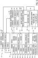
- FIG. 3 is a block diagram of example components of the propulsion system 10.
- the propulsion system 10 may include the surface stator matrix 24, one or more roaming vehicles 12, the control system 18, the position monitoring system 16, and the motor drive matrix 20.
- the propulsion system 10 may be configured to control the transportation of the roaming vehicle 12 across the running surface 22 where the surface stator matrix 24 is installed.
- the control system 18, the position monitoring system 16, the motor drive matrix 20, the roaming vehicle 12, and the surface stator matrix 24 may include various components that enable controlled movement of the roaming vehicle 12.
- the control system 18 may include a processor 30, a memory 32, a communication module 34, and a power supply 36.
- the processor 30, which may represent one or more processors, may be any type of computer processor or microprocessor capable of executing computer-executable code.
- the memory 32 which may represent one or more memory components, may be any suitable articles of manufacture that can serve as media to store processor-executable code, data, or the like. These articles of manufacture may represent tangible, non-transitory computer-readable media (e.g., any suitable form of tangible memory or storage) that may store the processor-executable code used by the processor 30 to control aspects of the presently disclosed embodiments, such as determining which SSLIMs 14 to activate and the magnitude and direction of their magnetic fields.
- the memory 32 may also be used to store the vehicle information received from the position monitoring system 16.
- the communication module 34 may be a wireless or wired communication component that may facilitate communication with the position monitoring system 16, the roaming vehicle 12, and the motor drive matrix 20.
- the communication module 34 may include a wireless card or data port (e.g., Ethernet connection) capable of transmitting and receiving data.
- the processor 30 may instruct the communication module 34 to send command instructions (e.g., SSLIM 14 identifier, activation/deactivation timing, force direction, amount of force to apply) to the motor drive matrix 20, which may supply electric current to the SSLIMs 14 accordingly.
- the power supply 36 may be any suitable power supply, including, but not limited to, a battery, for the control system 18.
- the position monitoring system 16 may include a processor 38, a memory 40, a communication module 42, and a sensor 44. It should be noted that although the position monitoring system 16 is depicted as a separate component from the control system 18, in some embodiments, the position monitoring system 16 may be included in the control system 18.
- the processor 38 which may represent one or more processors, may be any type of computer processor or microprocessor capable of executing computer-executable code.
- the memory 40 which may represent one or more memory components, may be any suitable articles of manufacture that can serve as media to store processor-executable code, data, or the like.
- These articles of manufacture may represent tangible, non-transitory computer-readable media (e.g., any suitable form of tangible memory or storage) that may store the processor-executable code used by the processor 38 to acquire vehicle information about the roaming vehicle 12, such as position and velocity of the roaming vehicle 12, and transmit the vehicle information to the control system 18, among other things.
- the memory 40 may also be used to store the vehicle information acquired by the sensor 44.
- the communication module 42 may be a wireless or wired communication component that may facilitate communication with the control system 18 and/or the roaming vehicle 12.
- the communication module 42 may include a wireless card or data port (e.g., Ethernet connection) capable of transmitting and receiving data.
- the sensor 44 may include an optic system that utilizes a camera to enable the position monitoring system 16 to track certain vehicle information (e.g., position of roaming vehicle 12 and/or velocity of roaming vehicle 12).
- the processor 38 and the communication module 42 may use signal (e.g., radio) triangulation to triangulate a signal emitted from the roaming vehicle 12 through a network to which the position monitoring system 16 and the roaming vehicle 12 are connected.
- the processor 38 may determine the location of the roaming vehicle 12 on the surface stator matrix 24.
- the vehicle information obtained by the position monitoring system 16 may be sent to the control system 18, which in turn determines which SSLIMs 14 to activate/deactivate and/or the performance (direction and strength of the magnetic fields) of the SSLIMs 14.
- the power supply 46 may be any suitable power supply, including, but not limited to, a battery, for the position monitoring system 16.
- the motor drive matrix 20 may include a plurality of motor drives 48.
- the motor drives 48 may include variable frequency drives (VFDs) that may control the strength and direction of the magnetic field (e.g., corresponding to the direction and amount of thrust generated by the SSLIMs 14) by varying input frequency and voltage to the windings of the SSLIMs 14.
- VFDs variable frequency drives
- the number of motor drives 48 may be less than the total number of SSLIMs 14 included in the surface stator matrix 24. That is, in some embodiments, there may not be a one-to-one relationship between the number of motor drives 48 and SSLIMs 14 because only the SSLIMs 14 used in the roaming vehicle motion profile may be activated at any given time.
- the processor 30 of the control system 18 may multiplex the motor drives 48 to control only those SSLIMs 14 that are in a preconfigured roaming vehicle motion profile or are dynamically determined to be in the motion profile based on input from the user.
- the processor 30 considers the number of total windings of the SSLIMs 14 needed to motivate the roaming vehicle 12 based on factors such as static friction, rolling friction, inertia, maximum acceleration and velocity, and/or braking acceleration.
- the control system 18 may send control signals to a switching panel 50 (e.g., solid state switching panel) of the motor drive matrix 20 to control the motor drives 48 to drive the appropriate SSLIMs 14 at a particular time and continuously switch the control of the next SSLIMs 14 in the vehicle motion profile to available motor drives 48 to move the roaming vehicle 12 around the surface stator matrix 24 based on where the roaming vehicle 12 is located.
- the number of motor drives 48 used may be less than the number of SSLIMs 14.
- windings 25 and 26 of the SSLIMs 14 are wired directly to the switching panel 50 that switches the control of the SSLIMs 14 between motor drives 48 and/or directly to the motor drives 48.
- the motor drives 48 may be electrically coupled to the SSLIMs 14. Maintainability may be increased by the multiplexing scheme described above that may reduce the overall hardware count (e.g., number of drives) of the propulsion system 10. However, in some embodiments, the same number of motor drives 48 and SSLIMs 14 may be used.
- the roaming vehicle 12 components may include a processor 52, a memory 54, a communication module 56, a mechanical brake 58, a power supply 60, a wireless directional controller 62, speakers 64, lights 66, a restraint lock 68, a position tracking system 70, casters 72, a reaction plate (e.g., rotor) 74, a rectifier and power conditioner 76, and/or an induction coil 79.
- the processor 52 which may represent one or more processors, may be any type of computer processor or microprocessor capable of executing computer-executable code.
- the memory 54 which may represent one or more memory components, may be any suitable articles of manufacture that can serve as media to store processor-executable code, data, or the like.
- These articles of manufacture may represent tangible, non-transitory computer-readable media (e.g., any suitable form of tangible memory or storage) that may store the processor-executable code used by the processor 52 to perform the presently disclosed techniques, such as controlling the onboard electronics (communication module 56, wireless directional controller 62, position tracking system 70, speakers 64, lights 66, restraint locks 68, etc.) and/or brake 58.
- the memory 54 may also be used to store the vehicle's information such as size dimensions (e.g., weight, length, width, height), velocity, acceleration, and so forth.
- the communication module 56 may be a wireless communication component that may facilitate communication with the control system 18 and/or the position monitoring system 16. As such, the communication module 56 may include a wireless card capable of transmitting and receiving data. For example, the processor 52 may instruct the communication module 56 to send the vehicle information to the control system 18 so the control system 18 can determine which SSLIMs 14 to activate and how the SSLIMs 14 should be activated.
- the roaming vehicle 12 includes the reaction plate 74, casters 72, and the mechanical brake 58.
- the movements of the roaming vehicle 12 may include accelerating, decelerating, turning, and stopping of the roaming vehicle 12.
- the reaction plate 74 may include a reaction plate including a non-ferrous conductor plate and a ferrous (e.g., steel) backing plate.
- the reaction plate is a single continuous or monolithic non-ferrous plate attached or installed on to the bottom of the roaming vehicle 12.
- the reaction plate may encompass as much of the bottom area (or possibly larger) of the roaming vehicle 12 to provide sufficient surface area for interaction with the magnetic fields generated by the SSLIMs 14.
- the shape of the reaction plate may be any suitable shape, including circular, rectangular, square, or the like.
- the casters 72 may include any suitable rolling equipment, such as wheels, that enables multi-directional and unlimited orientation on the running surface 22.
- the casters 72 may be used to maintain an air gap between the stator 14 and the reaction plate 74, which increases efficiency of propulsion using the SSLIMs 14 by mitigating energy losses due to friction.
- the mechanical brake 58 may include a ferrous plate and a braking material on the ferrous plate. The ferrous plate is attracted to the magnetic field generated by the SSLIMs 14 underneath the reaction plate, which pulls the brake 58 down to contact the running surface 22. The braking material provides friction between the brake 58 and the running surface 22 to slow or stop the roaming vehicle 12.
- the roaming vehicle 12 may not include a power system that is used to supply power to a motor (SSLIM 14). As such, the roaming vehicle 12 may be lighter than other roaming vehicles 12 that include a power system. However, in some embodiments, the roaming vehicle 12 may include a power supply 60 that is charged using energy obtained by the induction coil 79 on the reaction plate 74 from the magnetic field of the SSLIMs 14. In some embodiments, the energy inducted may be rectified and conditioned by the rectifier and power conditioner 76 and used to power onboard electronics, such as the processor 52, the memory 54, the communication module 56, wireless directional controller 62, the speakers 64, the lights 66, the position tracking system 70, and/or restraint locks 68.
- the processor 52 the memory 54
- the communication module 56 wireless directional controller 62
- the speakers 64 the lights 66
- the position tracking system 70 and/or restraint locks 68.
- the speakers 64 and/or the lights 66 may be controlled by the processor 52 during certain parts of the ride to enhance the theme of the ride or enhance show elements in the roaming vehicle 12. Further, the user may use the wireless directional controller 62 to guide the roaming vehicle 12 around the surface stator matrix 24. For example, the desired direction may be transmitted to the control system 18, which may determine which SSLIMs 14 to activate to thrust the roaming vehicle 12 in the desired direction based on the user input. In some embodiments, the wireless directional controller 62 may be limited to enable the user to spin the roaming vehicle 12 but not actually control the gross movement direction of the roaming vehicle 12, or vice-versa.
- the user may spin the roaming vehicle 12 during a ride to look at a different scene or shoot at a target but the roaming vehicle 12 is still transported along a set path.
- the restraint locks 68 may be used to restrain the patrons in the roaming vehicle 12 (e.g., while the roaming vehicle 12 is in motion and/or stationary).
- the position tracking system 70 may monitor the position of the roaming vehicle 12 on the surface stator matrix 24.
- the position tracking system 70 interacts with sensors on the surface stator matrix 24. Each sensor represents a unique location (e.g., coordinates relative to one or more reference points) on the surface stator matrix 24.
- the position tracking system 70 includes a reader that may read the sensors to determine the position of the roaming vehicle 12 on the surface stator matrix 24. The reader may then supply the position information to the control system 18, which in turn determines which SSLIMs 14 to activate and how each should be activated.
- the position tracking system 70 may include RFID tags and/or emitted lasers to provide and/or acquire position information.
- the roaming vehicles 12 may not include the position tracking system 70. While FIG. 3 illustrates the tracking system 70 on the roaming vehicle 12, in other embodiments it is not present, which is indicated by the dashed lines.
- the determination of vehicle position is performed completely wayside. As an example, wayside determinations may be based on machine vision systems positioned above the roaming vehicle 12 and configured to monitor location or positioning thereof. Further, in some embodiments, the only power and control onboard the roaming vehicle 12 is that associated with entertainment (e.g. lighting and audio effects). The braking in such embodiments may be passively controlled and passenger restraints may be mechanically actuated.
- the passenger restraints may be electrically actuated through induction pickups.
- keeping navigation and other ride control wayside provides for efficient vehicle design and algorithmic control off board.
- the position tracking system 70 of the roaming vehicle 12 and the position monitoring system 16 may work in concert to acquire vehicle information (e.g., position and/or velocity) to send to the control system 18.
- the surface stator matrix 24 may include the SSLIMs (stators) 14 and an air supply 78.
- the SSLIMs 14 may be included in tile blocks 29.
- the tile blocks 29 may be arranged on a grid of the matrix 24 based on the desired performance of portions of the surface stator matrix 24 (e.g., larger SSLIMs 14 may be placed in portions where high acceleration and deceleration are desired).
- the tile blocks 29 may be readily removable from the surface stator matrix 24 to enable servicing or replacement.
- Vinyl e.g., linoleum
- Vinyl may be placed over each one of the tile blocks and may be used as a wear surface.
- one or more sheets of vinyl may be used to cover the tile blocks.
- the vinyl covering the tile blocks may serve as the running surface for the roaming vehicles 12.
- there may be a certain amount of distance between the tile blocks 29 e.g., between 0.1 centimeter and 0.5 centimeter. Maintaining a small air gap (e.g., within a certain threshold distance) between the stator and the rotor in linear induction motors may greatly enhance generation of a thrust vector and may increase efficiency of the motor.
- the vinyl or cover applied to the tile blocks 29 should be relatively thin and non-metallic.
- the architecture of the surface stator matrix 24 may enable a robust backup capability.
- the control system 18 may control an adjacent SSLIM 14 to produce the desired magnetic field.
- the adjacent SSLIM 14 may be located underneath the reaction plate 74 or near the reaction plate 74 and may produce an induction field that motivates the reaction plate 74.
- off tangent force vectoring may cause the use of the adjacent SSLIMs 14 to result in a less efficient motivating force.
- closed-loop feedback that modulates the drive time and/or current to all applicable SSLIMs 14 resulting in the planned motion profile and desired thrust vector as the roaming vehicle 12 traverses the surface stator matrix 24.
- the control system 18 may use the closed-loop feedback to detect the loss of certain windings of the SSLIMs 14 through back calculation of the resultant roaming vehicle 12 motion.
- the air supply 78 may be used to blow air through holes in the running surface 22 and float the roaming vehicle 12 on an air bearing.
- the SSLIMs 14 are controlling the position and rotation of the roaming vehicle 12.
- Such an embodiment may increase uptime (e.g., the attraction is operational) of the attraction because there are fewer components to maintain (e.g., tires, bearings, and wheels).
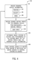
- process 90 for controlling the transportation of one or more roaming vehicles 12 using the propulsion system 10 is illustrated by the flow diagram in FIG. 4 .
- the process 90 may be performed by other control devices that may be capable of communicating with the control system 18, the position monitoring system 16, and/or the motor drive matrix 20, such as a computing device or other component associated with the propulsion system 10.
- the process 90 describes a number of operations that may be performed, it should be noted that the process 90 may be performed in different orders and that certain operations may not be performed.
- the process 90 may be implemented as computer instructions stored on the memory 32 of the control system 18.
- the control system 18 may receive (block 92) roaming vehicle information.
- the roaming vehicle information may be received from the position monitoring system 16 and/or the roaming vehicle 12 and may include information for one or more roaming vehicles 12 disposed on the running surface 22.
- the roaming vehicle information may include a position (data 94) of the roaming vehicle 12 on the running surface 22, a velocity (data 96) of the roaming vehicle 12, and/or a mass (data 98) of the roaming vehicle 12.
- the control system 18 may receive (block 100) the desired motion profile (e.g., path, velocity) for the roaming vehicle 12.
- the desired motion profile may be preconfigured (data 102) that includes the path for the roaming vehicle 12 and/or the desired velocities of the vehicle 12 at each portion of the surface stator matrix 24.
- the preconfigured motion profile may be obtained from the memory 32.
- the desired motion profile may include directions based on user input (data 104).
- the user input may enable the user to rotate the roaming vehicle 12 while the preconfigured path of the roaming vehicle 12 is still followed, the user input may enable the user to actually control the direction where the roaming vehicle 12 travels, the user input may enable the user to increase acceleration or deceleration of the roaming vehicle 12, or some combination thereof.
- the control system 18 may determine (block 106) which SSLIMs 14 to activate and performance of the SSLIMs (e.g., activation timing, amount of thrust) based at least on the desired motion profile and/or the roaming vehicle information. For example, in some embodiments at the beginning of a ride, the control system 18 may already know the position of the roaming vehicle 12 and may only use the motion profile to determine which SSLIMs 14 to activate, the times at which to activate each SSLIM 14, and the amount of thrust to generate as the roaming vehicle 12 traverses the surface stator matrix 24.
- the control system 18 may use the position 94 of the roaming vehicle 12 to determine which SSLIMs 14 are underneath or nearby the roaming vehicle 12 and select to activate those SSLIMs 14 as the roaming vehicle 12 traverses the surface stator matrix 24 (e.g., while deactivating SSLIMs 14 that are not selected). In some embodiments, a certain percentage of SSLIMs 14 around the roaming vehicle 12 may be activated to improve efficiency.
- determining the number of SSLIMs 14 to activate may depend on the velocity 96 of the roaming vehicle 12. For example, when first starting the roaming vehicle 12 in motion, it may be desirable to activate all SSLIMs 14 underneath the reaction plate to generate higher power and acceleration. When the roaming vehicle 12 reaches a desired velocity, the control system 18 may reduce the density of SSLIMs 14 that are active in the particular direction because fewer SSLIMs 14 may maintain a certain amount of energy to maintain the desired velocity. When the motion profile indicates a change of direction for the path of the roaming vehicle 12, then the magnitude of the thrust vector and density of SSLIMs 14 used may be increased because changing direction may require more torque than proceeding in a straight line. Thus, the density of SSLIMs 14 that are selected to activate under the roaming vehicle 12 at any one time may depend on the torque demand and current motion vector of the roaming vehicle 12.
- each SSLIM 14 may enable multi-directional movement of the roaming vehicle 12 to follow any motion profile.
- Each winding 25 and 26 may be individually energized.
- the force vector generated may be configured as desired because one winding 25 may provide a field in a first direction (e.g., forward or backward) and a second winding 26 may provide a field in a second direction (e.g., right or left).
- the windings 25 and 26 of the SSLIMs 14 may be activated to provide a force vector at any angle.
- the control system 18 may send (block 108) control signals to the motor drive matrix 20 to multiplex the motor drives 48 to control the SSLIMs 14 as desired.
- the switching panel 50 may be used to connect the motor drives 48 to the appropriate SSLIMs 14.
- the control system 18 may return to receiving roaming vehicle information at block 92 and repeat the process 90 to continuously navigate the roaming vehicle 12 around the running surface 22.
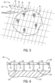
- FIG. 5 illustrates an overhead schematic of the reaction plate 74 located above the surface stator matrix 24.
- the reaction plate 74 may be formed from any suitable non-ferrous conductive material, such as aluminum, copper, zinc, amalgam of brass and copper, or the like.
- a ferrous (e.g., steel) backing plate may be disposed between the reaction plate 74 and the bottom of the roaming vehicle 12. As the magnetic field passes through the conductor of the reaction plate 74, the steel backing plate may return the field back to the SSLIM 14.
- the force vector may be generated by the opposing magnetic field of the conductor that is induced by eddy currents as the magnetic field of the SSLIM 14 passes through the conductor.
- one or more casters 72 may be attached to the base of the roaming vehicle 12.
- the casters 72 may include wheels that are used to roll the roaming vehicle 12 around the running surface 22.
- the casters 72 may be used to maintain a precise air gap between the reaction plate 74 and the surface stator matrix 24 to maintain an efficient induction field.
- the SSLIMs 14 of the surface stator matrix 24 may be included in tile blocks 29 and arranged in a grid pattern.
- the sub-floor support 110 may be used to elevate the surface stator matrix 24 off of a foundation 112 and provide room for wiring space 114, as illustrated in the cross-sectional view in FIG. 6 .
- the sub-floor support 110 may support a grid on which each of the tile blocks 29 including SSLIMs 14 is placed.
- the wiring of the SSLIMs 14 may be disposed in the wiring space 114 and may connect the SSLIMs 14 to the motor drives 48 and/or the switching panel 50.
- the tile blocks 29 (e.g., epoxy blocks) may generally be square shaped, rectangular shaped, circular shaped, or the like as described above and may include two orthogonally arranged windings 25 and 26 of the SSLIMs 14.
- FIGS. 7-15 generally illustrate examples of how various SSLIMs 14 located underneath or near the reaction plate 74 may be controlled to provide different thrust vectors and move the roaming vehicle 12 in desired directions. It should be noted that the number of SSLIMs 14 applied in the same direction increases the thrust in that direction. Further, pulsing of the SSLIMs 14 may facilitate certain motions. The processor 30 may determine the number of SSLIMs 14 to apply using physics modeling to change the thrust vector. Also, if a thrust vector is provided in one direction, an equal and opposite thrust may be provided to change the vector.
- FIG. 7 an overhead schematic illustrates SSLIMs 14 being controlled to produce a thrust vector in a forward direction in the reaction plate 74, in accordance with an embodiment.
- one or more SSLIMs 14 underneath the front, back, left side, and right side of the reaction plate 74 are providing a thrust in a forward direction.
- the thrust vector is in a forward direction as indicated by arrow 122.
- FIG. 8 is an overhead schematic illustrating SSLIMs 14 being controlled to produce a counter-clockwise thrust vector (indicated by arrow 124) in the reaction plate 74, in accordance with an embodiment.
- the counter-clockwise thrust vector 124 may spin the roaming vehicle 12.
- one or more SSLIMs 14 underneath the front and back of the reaction plate 74 may provide a thrust orthogonal (90 degrees to the left and right) (arrow 126 and 128) to the thrusts (arrows 130 and 132) produced by one or more SSLIMs 14 underneath the sides of the reaction plate 74.
- the thrust 128 produced in the left side of the reaction plate 74 is in a backward direction and the thrust 130 produced in the right side of the reaction plate 74 is in a forward direction.
- the thrust vector 124 may spin the roaming vehicle 12 in a counter-clockwise direction.
- FIG. 9 is an overhead schematic illustrating SSLIMs 14 being controlled to produce balanced thrust towards the edges of the reaction plate 74 so there is no thrust vector (dot 134) applied to the reaction plate 74, thereby holding the roaming vehicle 12 in place, in accordance with an embodiment.
- one or more SSLIMs 14 underneath the front and back of the reaction plate 74 may thrust in opposite directions towards the edges of the reaction plate 74, as shown by arrow 136 representing thrust in a forward direction and arrow 138 representing thrust in a backward direction.
- one or more SSLIMs 14 underneath the left and right sides of the reaction plate 74 may thrust in opposite directions towards the edges of the reaction plate 74, as shown by arrow 140 representing thrust in a left direction and arrow 142 representing thrust in a right direction, to hold the reaction plate 74 in place.
- the thrusts 136, 138, 140, and 142 may produce a balanced pattern of thrusts from the SSLIMs 14 that do not result in a vectored force applied to the reaction plate 74.
- FIG. 10 is an overhead schematic illustrating SSLIMs 14 being controlled to produce a thrust vector (arrow 144) in a forward and left direction in the reaction plate 74, in accordance with an embodiment.
- the thrust vector 144 may be produced by one or more SSLIMs 14 underneath the front and back of the roaming vehicle 12 generating thrust (arrow 146) in a forward direction and one or more SSLIMs 14 underneath the left and right sides of the roaming vehicle 12 generating thrust (arrow 148) in a left direction.
- the combined thrusts may generate a thrust vector that provides an angled direction (e.g., 45 degrees) of travel for the roaming vehicle 12.
- FIG. 11 is an overhead schematic illustrating SSLIMs 14 being controlled to produce a thrust vector (arrow 150) in a forward and slightly left direction in the reaction plate, in accordance with an embodiment.
- thrust vector 150 in FIG. 11 is angled left to a lesser degree as a result of activating more SSLIMs 14 underneath the front and back of the roaming vehicle 12 to generate more thrust (arrows 152) in the forward direction than SSLIMs 14 underneath the left and right sides generating thrust (arrows 154) in the left direction.
- the resulting thrust vector 150 is directed more forward than to the left as a result of the thrust generated by the SSLIMs 14 underneath the front and back exceeding the thrust generated by the SSLIMs 14 underneath the left and right sides of the reaction plate 74. It should be understood that the angle of direction of the thrust vector may be finely tuned by activating appropriate SSLIMs 14.
- FIG. 12 is an overhead schematic illustrating SSLIMs 14 being controlled to produce a thrust vector (arrows 156) in a forward direction while rotating counter-clockwise in the reaction plate 74, in accordance with an embodiment.
- a thrust vector arrows 156
- FIG. 12 To generate the forward, counter-clockwise rotating thrust vector 156, one or more SSLIMs 14 underneath the right and left sides of the reaction plate 74 may generate thrust (arrows 158) in the forward direction and one or more SSLIMs 14 underneath the front and back of the reaction plate 74 may generate thrust (arrows 159 and 160) in opposite directions that are orthogonal to the direction of side thrusts 158.
- thrust 159 is in a left direction and thrust 160 is in a right direction, which may cause the roaming vehicle 12 to spin counter-clockwise, while thrusts 158 cause the roaming vehicle 12 to move in a forward direction.
- the SSLIMs 14 may be controlled to spin the roaming vehicle 12 in a clockwise direction.
- FIG. 13 is an overhead schematic illustrating SSLIMs 14 being controlled to produce a strong thrust vector (arrow 161) in a forward direction in the reaction plate 74 to increase acceleration, in accordance with an embodiment.
- a higher density of SSLIMs 14 are activated and may generate thrusts (arrows 162) in a forward direction.
- the higher density of SSLIMs 14 activated in the same direction increase the thrust in that vector.
- FIG. 14 is an overhead schematic illustrating SSLIMs 14 being controlled to produce a braking thrust vector (arrow 164) in a forward direction in the reaction plate 74, in accordance with an embodiment.
- the thrust vector arrow 164 is reduced in size to represent the effect of the braking thrust (arrows 166) being generated by SSLIMs 14 underneath the reaction plate 74 on the thrust vector 164 while the roaming vehicle 12 is in motion.
- the SSLIMs 14 underneath the roaming vehicle 12 may be controlled to generate thrust (arrows 166) in an opposing direction to the direction of movement.
- FIG. 15 is an overhead schematic illustrating SSLIMs 14 being controlled to produce a thrust vector (arrow 168) in the reaction plate 74 that curve the forward motion of the roaming vehicle 12 to the right without rotating the roaming vehicle 12, in accordance with an embodiment.
- the roaming vehicle 12 is traveling forward due to thrust (arrows 170) generated by SSLIMs 14 underneath the roaming vehicle 12.
- the control system 18 may determine the position of the roaming vehicle 12 and instruct the motor drive matrix 20 to activate SSLIMs 14 in the motion path of the roaming vehicle 12 in time to interact with the reaction plate 74 as the roaming vehicle 12 traverses the running surface to direct the roaming vehicle 12 in the desired direction.
- various rows of SSLIMs 14 may produce thrust in the desired direction incrementally. For example, to curve the motion of the roaming vehicle 12 to the right, a first row 172 of SSLIMs 14 may generate thrust (arrows 174) in a right direction to force the vehicle 12 right in one increment. In the next increment, a second row 176 of SSLIMs 14 may generate thrust (arrows 178) in a forward direction to keep the roaming vehicle 12 moving forward. Then, in the next increment, a third row 180 of SSLIMs 14 may generate thrust (arrows 182) in the right direction to force the roaming vehicle 12 to the right.
- the control system 18 may control additional SSLIMs 14 in the motion path of the roaming vehicle 12 to continue to produce the curved motion by producing a sum thrust vector directed in any desired angle.
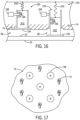
- FIG. 16 is a side view of the mechanical brake 58 included in the roaming vehicle 12, in accordance with an embodiment.
- the mechanical brake 58 is shown as undeployed, and, in a second view 192, the mechanical brake 58 is show as deployed.
- the mechanical brake 58 may include a ferrous plate 194 (e.g., steel) with a brake pad material for high frictional ⁇ . The brake pad material may provide sufficient friction to hold the mechanical brake 58 and roaming vehicle 12 in place when in contact with the running surface 22.
- the mechanical brake 58 may include a recess 196 in which a locking pin 198 is inserted to hold the mechanical brake 58 in the undeployed position as the mechanical brake 58 passes through magnetic fields generated by the SSLIMs 14 on the surface stator matrix 24.
- the control system 18 may send a control signal to the roaming vehicle 12 to release the locking pin 198.
- the magnetic field generated by the SSLIMs 14 may attract the ferrous plate 194 of the mechanical brake 58, which may cause the ferrous plate 194 to be pulled towards and contact the running surface 22 of the surface stator matrix 24, as shown in view 192.
- certain planned areas of the surface stator matrix 24 may provide a balanced (e.g., not applying a vectored force on the reaction plate 74) pattern of magnetic fields that activate deployment of the mechanical brake 58.
- the mechanical brake 58 may be deployed when the magnetic field generated by the SSLIMs 14 is strong enough to overcome the force of the locking pin 198 holding the mechanical brake 58 in the undeployed position. It should be noted that the use of the mechanical brake 58 may be planned for certain portions of the roaming vehicle 12 motion profile or its use may be unplanned (e.g., in the case of an unexpected event).
- the efficiency of the holding force used by the mechanical brake 58 may be small enough that the presence of a relatively low electromotive force threshold can be planned as an idle current allowing for a near minimum number of SSLIMs 14 to remain active for a minimum motion profile to motivate the mechanical brake 58.
- a spring return 200 attached to a base 202 of the mechanical brake 58 may pull the mechanical brake 58 back into slot 204 when the magnetic field (e.g., electromotive force) attracting the ferrous plate 194 is reduced (e.g., not strong enough to overcome the pulling force of the spring return 200) or turned off.
- the mechanical brake 58 may be locked into the undeployed position by the locking pin 198 being reinserted into the recess 196.
- FIG. 17 is an overhead schematic of a number of mechanical brake 58 and caster 72 locations in the reaction plate 74 of the roaming vehicle 12, in accordance with an embodiment.
- the size and/or number of the mechanical brakes 58 may be determined based on the planned mass for the roaming vehicle 12 (e.g., planned mass of vehicle components and occupying patrons) and the velocity of the roaming vehicle 12. In some embodiments, the number and/or size of the mechanical brakes 58 may be determined based on the highest planned velocity for a roaming vehicle motion profile and a largest planned mass for the roaming vehicle 12.
- the number of mechanical brakes 58 that are deployed may depend on how much holding force is needed to stop the roaming vehicle 12 based on the velocity and mass of the roaming vehicle 12.
- five mechanical brakes 58 are included in the reaction plate 74 of the roaming vehicle 12.
- One mechanical brake 58 is located in each of four corners of the reaction plate 74 and one mechanical brake 58 is located in the center of the reaction plate 74. It should be understood that any suitable number of mechanical brakes 58 may be used.
- the number of casters 72 and the location of the casters 72 at each point on the reaction plate 74 may vary as desired to maintain a sufficient air gap between the reaction plate 74 and the SSLIMs 14. For example, if the reaction plate 74 does not include casters 72 at certain portions of the reaction plate 74, those portions may wobble (e.g., move up and down) while the roaming vehicle 12 traverses the surface stator matrix 24. The up and down movement of the portions of the reaction plate 74 may vary the distance of the air gap and reduce efficiency of the SSLIMs 14. Also, the size of the casters 72 may be reduced to enable a relatively minor air gap between the reaction plate 74 and the SSLIMs 14.
- the reaction plate 74 includes six casters 72: two on the left and right sides of the reaction plate 74, one on the front of the reaction plate 74, and one on the back of the reaction plate 74. Such an arrangement may inhibit up and down movement of the reaction plate 74 as the roaming vehicle 12 traverses the surface stator matrix 24 to maintain a precise air gap. It should be understood that any suitable number, size, and/or location of the casters 72 may be used to maintain the precise air gap.
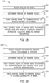
- FIGS. 18-21 are flow diagrams of various processes for braking or holding the roaming vehicle 12 and/or releasing the roaming vehicle 12.
- the following description of the processes in FIGS. 18-21 are described as being performed by the control system 18, it should be noted that some or all of the processes may be performed by other control devices that may be capable of communicating with the control system 18, the position monitoring system 16, and/or the motor drive matrix 20, such as a the roaming vehicle 12, computing device, or other component associated with the propulsion system 10.
- the following processes describe a number of operations that may be performed, it should be noted that the processes may be performed in different orders and that certain operations may not be performed.
- the processes may be implemented as computer instructions stored on the memory 32 of the control system 18.
- FIG. 18 is a flow diagram of a process 210 for deploying the mechanical brake 58 of FIG. 16 , in accordance with an embodiment.
- the control system 18 may receive (212) a request to brake.
- the request to brake may be received from the roaming vehicle 12 (e.g., based on user input), may be received as part of the motion profile obtained from the memory 32, or the like.
- the control system 18 may determine (block 214) the position of the roaming vehicle 12 using vehicle information from the position monitoring system 16 or from the position tracking system 70. That is, the control system 18 may determine the position of the roaming vehicle 12 relative to the surface stator matrix 24 based on the vehicle information received.
- the control system 18 may send (block 216) a control signal to the roaming vehicle 12 to actuate (e.g., retract) the locking pin 198 of one or more mechanical brakes 58.
- the control system 18 may also send (218) a control signal to the appropriate motor drives 48 and/or switching panel 50 to control the SSLIMs 14 near the roaming vehicle 12 to provide a magnetic field with sufficient strength to pull the ferrous material of the one or more mechanical brakes 58 to contact the surface of the running surface 22.
- the holding force of the one or more deployed mechanical brakes 58 may cause the roaming vehicle 12 to stop moving.
- FIG. 19 is a flow diagram of a process 220 for retracting the mechanical brake 58 of FIG. 16 , in accordance with an embodiment.
- the control system 18 may receive (block 222) a request to move the roaming vehicle 12 while one or more mechanical brakes 58 are deployed.
- the request may be received from the roaming vehicle 12 (e.g., based on user input), may be received as part of the motion profile obtained from the memory 32, or the like.
- the control system 18 may determine (block 224) the position of the roaming vehicle 12 using vehicle information from the position monitoring system 16 or from the position tracking system 70. That is, the control system 18 may determine the position of the roaming vehicle 12 relative to the surface stator matrix 24 based on the vehicle information received.
- the control system 18 may send (block 226) a control signal to appropriate motor drives 48 and/or switching panel 50 to control the SSLIMs 14 providing the magnetic field attracting the mechanical brake 58 such that the brake 58 retracts. That is, the magnetic field generated by the SSLIMs 14 may be reduced to an insufficient strength to overcome the force of the spring return 200, thereby enabling the spring return 200 to pull the mechanical brake 58 away from the SSLIMs 14 into slot 204 for storage.
- the control system 18 may send a control signal to the roaming vehicle 12 to actuate (e.g., deploy) the locking pin 198 into recess 196 to secure the mechanical brake 58 in the undeployed position.
- FIG. 20 is a flow diagram of a process 230 for applying magnetic force using the SSLIMs 14 to hold the roaming vehicle 12 in place, in accordance with an embodiment.
- the control system 18 may receive (block 232) a request to slow down or stop the roaming vehicle 12.
- the request may be received from the roaming vehicle 12 (e.g., based on user input), may be received as part of the motion profile obtained from the memory 32, or the like.
- the control system 18 may determine (block 234) the position of the roaming vehicle 12 using vehicle information from the position monitoring system 16 or from the position tracking system 70. That is, the control system 18 may determine the position of the roaming vehicle 12 relative to the surface stator matrix 24 based on the vehicle information received.
- the control system 18 may send (block 236) control signals to the appropriate motor drives 48 and/or switching panel 50 to control the SSLIMs 14 near the roaming vehicle 12 (e.g., underneath and/or around the location of the roaming vehicle 12) to hold the roaming vehicle 12 in place.
- one SSLIM 14 underneath the front, back, left side, and right side of the reaction plate 74 may generate near equal and balanced thrust towards the center of the reaction plate 74. As a result, no thrust vector may be generated and the roaming vehicle 12 may be held in a stationary position.
- a similar scenario may occur when the SSLIMs 14 on equivalent positions on opposite sides of the reaction plate 74 thrust towards the outer edges of the reaction plate 74.
- FIG. 21 is a flow diagram of a process 240 for releasing the holding magnetic force using the SSLIMs 14 to enable the roaming vehicle 12 to move, in accordance with an embodiment.
- the control system 18 may receive (block 242) a request to move the roaming vehicle 12 while the magnetic field of the SSLIMs 14 is holding the roaming vehicle 12 in place.
- the request may be received from the roaming vehicle 12 (e.g., based on user input), may be received as part of the motion profile obtained from the memory 32, or the like.
- the control system 18 may determine (block 244) the position of the roaming vehicle 12 using vehicle information from the position monitoring system 16 or from the position tracking system 70. That is, the control system 18 may determine the position of the roaming vehicle 12 relative to the surface stator matrix 24 based on the vehicle information received.
- the control system 18 may send (block 246) control signals to the appropriate motor drives 48 and/or switching panel 50 to control the SSLIMs 14 holding the roaming vehicle 12 in place to change or remove the magnetic field to enable the roaming vehicle 12 to move.
- the control system 18 may change the thrust vector generated by the SSLIMs 14 by commanding that one or more SSLIMs underneath the reaction plate 74 to generate thrust in the reaction plate 74 in a forward direction.
- the roaming vehicle 12 may be released from the stationary position and be motivated in the direction of the thrust vector.
- FIG. 22 is a schematic diagram illustrating using an induction coil 79 on the reaction plate 74 to pick up energy from the SSLIM 14 to power the onboard electronics (e.g., processor 52, memory 54, communication module 56, power supply 60, wireless directional controller 62, speakers 64, lights 66, restraint locks 68, position tracking system 70) of the roaming vehicle 12, in accordance with an embodiment.
- the onboard electronics e.g., processor 52, memory 54, communication module 56, power supply 60, wireless directional controller 62, speakers 64, lights 66, restraint locks 68, position tracking system 70
- one or more rectifiers and/or power conditioners 76 may be used to convert, condition, amplify, or some combination thereof, the inducted energy from the magnetic field generated by the SSLIM 14.
- the rectifier may 78 may convert the AC power to DC power that is used to power the onboard electronics.
- the size of an air gap 252 between the reaction plate 74 and the SSLIM 14 may affect the strength of the induction field generated by the SSLIM 14 and the amount of energy picked up by the induction coil 79. Thus, it may be desirable to maintain a relatively small air gap 252 to enhance the induction field.
Landscapes
- Engineering & Computer Science (AREA)
- Mechanical Engineering (AREA)
- Power Engineering (AREA)
- Transportation (AREA)
- Physics & Mathematics (AREA)
- Electromagnetism (AREA)
- Automation & Control Theory (AREA)
- Sustainable Development (AREA)
- Life Sciences & Earth Sciences (AREA)
- Sustainable Energy (AREA)
- Aviation & Aerospace Engineering (AREA)
- Radar, Positioning & Navigation (AREA)
- Remote Sensing (AREA)
- General Physics & Mathematics (AREA)
- Chemical & Material Sciences (AREA)
- Combustion & Propulsion (AREA)
- Electric Propulsion And Braking For Vehicles (AREA)
- Control Of Vehicles With Linear Motors And Vehicles That Are Magnetically Levitated (AREA)
- Linear Motors (AREA)
Description
- The present disclosure relates generally to a motion control mechanism and, more particularly, to systems and methods for braking or propelling a roaming vehicle.
- This section is intended to introduce the reader to various aspects of art that may be related to various aspects of the present techniques, which are described and/or claimed below. This discussion is believed to be helpful in providing the reader with background information to facilitate a better understanding of the various aspects of the present disclosure. Accordingly, it should be understood that these statements are to be read in this light, and not as admissions of prior art.
- Generally, vehicles include motors for driving the vehicles between locations. Motors are most often used to generate motive force, but certain types of motors can be used to both accelerate (e.g., start) and decelerate (e.g., stop) a vehicle. Indeed, there are a variety of motor arrangements used to accelerate and decelerate a vehicle carrying passengers. For example, trains, powered roller coasters, and the like, may utilize one or more electric motors with rotating elements to accelerate and decelerate a ride vehicle or car around a track. However, electric motors with rotating elements may be prone to mechanical issues and high downtime (e.g., the ride is inoperable) due to the rotating elements.
- Document
WO2016022269 discloses a motion control mechanism relating to systems and methods for braking or launching a ride vehicle. - Document
US6445093 discloses a compact motor with a coil geography providing an energy efficient operation within the field of high precision motors for use in lithography systems. DocumentUS7224252 discloses an adaptive magnetic levitation apparatus that includes a base array of computer-controlled electromagnets, for providing movement of a levitated platform in two or three dimensions. - In accordance with an embodiment of the present disclosure, a propulsion system includes one or more roaming vehicles comprising a reaction plate installed on a bottom of each of the one or more roaming vehicles; wherein the reaction plate comprises a non-ferrous conductor; a surface stator matrix installed with a running surface for the one or more roaming vehicles and comprising a plurality of single sided linear induction motors (SSLIMs), wherein each of at least a portion of the plurality of SSLIMs include two windings installed orthogonally to one another, the two windings being individually energisable to generate magnetic fields that provide a first force in a first direction and a second force in a second coplanar direction as the reaction plate of each of the one or more roaming vehicles passes through the magnetic fields, thereby producing a force vector in any direction across the surface stator matric on the one or more roaming vehicles; a plurality of motor drives configured to electrically couple to the plurality of SSLIMs via a switching panel; a control system configured to: receive information related to the one or more roaming vehicles; receive a desired motion profile for the one or more roaming vehicles across the surface stator matrix; determine which of the plurality of SSLIMs to activate, and for each activated SSLIM, adjust the current supplied to the windings based on the desired motion profile, the information, or some combination thereof; and send control signals to the plurality of motor drives to control the plurality of SSLIMs to generate force vectors to produce the motion profile, wherein the motor drives control the plurality of SSLIMs to produce the motion profile by activating a subset of the plurality of SSLIMs underneath the reaction plate in time to generate a force vector in the reaction plate that causes the one or more roaming vehicles to follow a path specified by the desired motion profile as the one or more roaming vehicles traverse the running surface.
- In accordance with another embodiment of the present disclosure, a method, includes receiving, via a control system, information related to one or more roaming vehicles disposed on a running surface of a surface stator matrix, wherein the one or more roaming vehicles comprise a reaction plate attached to a bottom of each respective roaming vehicle of the one or more roaming vehicles, wherein the reaction plate comprises a non-ferrous conductor, wherein the surface stator matrix comprises a plurality of single sided linear induction motors (SSLIMs) each including two windings arranged orthogonal to each other, the two windings being individually energisable to generate magnetic fields that provide a first force in a first direction and a second force in a second coplanar direction as the reaction plate of each of the one or more roaming vehicles passes through the magnetic fields, thereby producing a force vector in any direction across the surface stator matrix on the one or more roaming vehicles; receiving, via the control system, a desired motion profile for the one or more roaming vehicles across the surface stator matrix; determining, via the control system, a selection of the plurality of SSLIMs to activate and, for each activated SSLIM, adjusting the current supplied to the windings based on the desired motion profile, the information, or some combination thereof; and sending, via the control system, control signals to the plurality of motor drives configured to electrically couple to the plurality of SSLIMs via a switching panel, to control the selection of the plurality of SSLIMs to generate force vectors to produce the motion profile, wherein the motor drives control the plurality of SSLIMs to produce the motion profile by activating a subset of the plurality of SSLIMs underneath the reaction plate in time to generate a force vector in the reaction plate that causes the one or more roaming vehicles to follow a path specified by the desired motion profile as the one or more roaming vehicles traverse the running surface.
- Further embodiments are defined by the appended claims.
- These and other features, aspects, and advantages of the present disclosure will become better understood when the following detailed description is read with reference to the accompanying drawings in which like characters represent like parts throughout the drawings, wherein:
-
FIG. 1 is a schematic of a propulsion system for controlling the movement of roaming vehicles that includes single sided linear induction motors (SSLIMs), a position monitoring system, a control system, and a motor drive matrix, in accordance with an embodiment of the present disclosure; -
FIG. 2 is an overhead view of a SSLIM fromFIG. 1 , in accordance with an embodiment of the present disclosure. -
FIG. 3 is a block diagram of example components of the propulsion system ofFIG. 1 , in accordance with an embodiment of the present disclosure; -
FIG. 4 is a flow diagram of a process for controlling the movement of one or more roaming vehicles using the propulsion system ofFIG. 1 , in accordance with an embodiment of the present disclosure; -
FIG. 5 is an overhead schematic of a roaming vehicle having a reaction plate located above a surface stator matrix, in accordance with an embodiment of the present disclosure; -
FIG. 6 is a cross-sectional view of the surface stator matrix taken along section 5-5 ofFIG. 5 , in accordance with an embodiment of the present disclosure; -
FIGS. 7-15 are overhead schematics illustrating the manner in which the magnetic field produced by a series of SSLIMs can be controlled to interact with a reaction plate of a roaming vehicle to produce different thrust vectors, in accordance with an embodiment of the present disclosure; -
FIG. 16 is a cross-sectional side view of a mechanical brake included in the roaming vehicle, in accordance with an embodiment of the present disclosure; -
FIG. 17 is an overhead schematic representing an example arrangement of mechanical brake and caster locations in a reaction plate of the roaming vehicle, in accordance with an embodiment of the present disclosure; -
FIG. 18 is a flow diagram of a process for deploying the mechanical brake ofFIG. 16 , in accordance with an embodiment of the present disclosure; -
FIG. 19 is a flow diagram of a process for retracting the mechanical brake ofFIG. 16 , in accordance with an embodiment of the present disclosure; -
FIG. 20 is a flow diagram of a process for applying magnetic force using the SSLIMs to hold the roaming vehicle in place, in accordance with an embodiment of the present disclosure; -
FIG. 21 is a flow diagram of a process for releasing the holding magnetic force using the SSLIMs to enable the roaming vehicle to move, in accordance with an embodiment of the present disclosure; and -
FIG. 22 is a schematic diagram illustrating using an induction coil to pick up energy to power onboard electronics of the roaming vehicle, in accordance with an embodiment of the present disclosure. - One or more specific embodiments of the present disclosure will be described below. In an effort to provide a concise description of these embodiments, all features of an actual implementation may not be described in the specification. It should be appreciated that in the development of any such actual implementation, as in any engineering or design project, numerous implementation-specific decisions must be made to achieve the developers' specific goals, such as compliance with system-related and business-related constraints, which may vary from one implementation to another. Moreover, it should be appreciated that such a development effort might be complex and time consuming, but would nevertheless be a routine undertaking of design, fabrication, and manufacture for those of ordinary skill having the benefit of this disclosure.
- When introducing elements of various embodiments of the present disclosure, the articles "a," "an," "the," and "said" are intended to mean that there are one or more of the elements. The terms "comprising," "including," and "having" are intended to be inclusive and mean that there may be additional elements other than the listed elements.
- In certain applications, such as an amusement park attraction, high uptime (e.g., the amusement park attraction is operational) is desirable to ensure that patrons are satisfied by being given the opportunity to ride or experience the amusement park attraction. However, some amusement park attractions use equipment to propel vehicles, such as rotary motors, that experience strong mechanical stresses in operation that may wear on certain parts of the equipment over time. For example, a shaft of a rotary motor or contact elements of the propulsion system, such as tires or tracks, may degrade after extended use. In addition, some roaming vehicles in attractions include onboard propulsion equipment (e.g., a motor and a power source for the motor) that may add weight to the vehicle, thereby affecting its performance. It is now recognized that it may be desirable to use equipment to propel vehicles in the attractions that are relatively low maintenance and/or located remote from the vehicle.
- It is now recognized that it may be desirable to use electric motors without rotating elements, such as linear induction motors (LIMs) or linear synchronous motors (LSMs). The LIMs and/or LSMs may accelerate a ride vehicle or car along a track and bring the ride vehicle or car to rest at a desired location. Additionally, certain ride vehicles may be propelled around a course and stopped as desired using LIMs and/or LSMs. LIMs and/or LSMs generally include electric motors having stators and rotors in a linear configuration. Rather than producing torque with rotating elements, LIMs and LSMs produce the force to move the roaming vehicle by producing a linear magnetic field to attract or repel magnets or conductors in the field.
- Some embodiments of the present disclosure generally relate to using a propulsion system that includes a running surface (e.g., floor) that includes single sided linear induction motors (SSLIMs), and a roaming vehicle that includes a reaction plate to interact with the SSLIMs. In some embodiments, the roaming vehicles may not include a power system to control the SSLIMs (e.g., the power system may be under the floor surface), thereby reducing the weight of the roaming vehicles. Further, the propulsion system may use relatively few moving parts by employing the SSLIMs to propel the roaming vehicle. Accordingly, one benefit enabled using the disclosed propulsion system is a reduction in maintenance and downtime as compared to other systems. In addition, using the SSLIMs to move the roaming vehicle may be highly dynamic in that a control system can control and adjust how each SSLIM is activated to move the roaming vehicle in any desired direction and path. Indeed, there may be numerous preconfigured roaming vehicle motion profiles (e.g., path, velocity) that are stored as instructions on one or more tangible, computer-readable mediums and executed by on one or more processors based at least on the arrangement of obstacles or show set on the running surface. If the obstacles or show set are changed (e.g., the ride is redesigned or themed for a special event), a preconfigured roaming vehicle motion profile may be implemented, the motion profile including instructions for which SSLIMs to activate and when to activate them based on the path and velocity of the roaming vehicle. Further, the roaming vehicle motion profile may be dynamically adjusted based on input from the patron occupying the roaming vehicle. Thus, another benefit of the disclosed embodiments may be rapid or real-time motion profile adjustment to provide users with different experiences during the ride or during subsequent rides.
- With the foregoing in mind,
FIG. 1 is a schematic of an embodiment of apropulsion system 10 for controlling the transportation of aroaming vehicle 12 that includes single sided linear induction motors (SSLIMs) 14, aposition monitoring system 16, acontrol system 18, and amotor drive matrix 20, in accordance with an embodiment. Although just oneroaming vehicle 12 is depicted, it should be understood that thepropulsion system 10 may be used to control the transportation of numerous roaming vehicles 12 (e.g., between 1 and 10). As depicted, theroaming vehicle 12 is disposed on a two-dimensional (e.g., including x- and y-axes) running surface 22 (e.g., a floor) that includes amatrix 24 of installedSSLIMs 14. Thematrix 24 may be referred to as thesurface stator matrix 24 herein. The SSLIMs 14 may be constructed as tile blocks for the runningsurface 22, as described in detail below. Eachroaming vehicle 12 may be considered an automated guided vehicle (AGV) and may include a reaction plate and a backing plate (e.g., steel) secured to a bottom of theroaming vehicle 12. As described below, the reaction plate may include a non-ferrous conductor (e.g., aluminum, copper, zinc, amalgam of brass and copper). TheSSLIMs 14 may each represent a stator and the reaction plate and the steel backing plate of the roamingvehicle 12 may represent a rotor, when theSSLIMs 14 and the reaction plate interact to produce motion of the roamingvehicle 12. As described in detail below, thesurface stator matrix 24 may be controlled using theposition monitoring system 16, thecontrol system 18, and themotor drive matrix 20. - Although the following discussion focuses on
SSLIMs 14 being used in thepropulsion system 10, it should be noted that, in some embodiments a linear synchronous motor (LSM) including a rare earth magnet may be used. In such embodiments, the stator may include an electromagnetic motor winding on one side of an air gap and the rotor may include one or more permanent magnets on the other side of the air gap. For example, the stator in the LSM may be located in the running surface and the rotor may be located on the bottom of the roamingvehicle 12, or vice versa. - Returning to the depicted embodiment including the
SSLIMs 14, the number and size of theSSLIMs 14 included in thesurface stator matrix 24 disposed in the runningsurface 22 may be influenced by one or more factors. For example, theSSLIMs 14 to reaction plate ratio may influence motion performance (e.g., speed and direction of movement) of the roamingvehicle 12. A greater number ofSSLIMs 14 interacting with a reaction plate may result in finer steering motion control with diminished acceleration. In contrast, a smaller number of SSLIMs 14 per reaction plate may result in higher acceleration and gross motion control. The density ofSSLIMs 14 in the runningsurface 22 may be determined based on desired performance of the roamingvehicle 12. Additionally, someSSLIMs 14 may be different sizes (e.g., larger) thanother SSLIMs 14. In some embodiments, various portions of the runningsurface 22 may include different densities ofSSLIMs 14 than other portions based on the desired performance. When theSSLIMs 14 are placed in thesurface stator matrix 24, theSSLIMs 14 may be activated to control the motion of the roamingvehicle 12. - In some embodiments, the
SSLIMs 14 may be bi-directional because each SSLIM 14 may includewindings SSLIM 14 inFIG. 2 . Thewindings steel laminate SSLIMs 14. TheSSLIMs 14 may be placed in a slat and encased in an epoxy to create tile blocks 29 (e.g., plastic resin block). The tile blocks 29 including theSSLIMs 14 may be installed in a grid pattern to form the runningsurface 22. - To propel the roaming
vehicle 12 around the runningsurface 22, an electric current may be applied to theappropriate windings SSLIMs 14 to thrust the roamingvehicle 12 in a desired direction. Thewindings respective roaming vehicle 12. The amount of acceleration of the roamingvehicle 12 may be proportional to the sum magnetic field produced by theSSLIMs 14. The sum magnetic field may be controlled by the amount of electric current supplied to thewindings SSLIMs 14. - One winding 25 may provide a first motive force in a first direction and another winding 26 may provide a second motive force in a second direction, depending on how the
SSLIM 14 is arranged in thesurface stator matrix 24. For example, the first direction may be longitudinal and the second direction may be lateral. In a more specific example, the second direction may be crosswise relative to the first direction, such as 90 degrees from and coplanar with the first direction. In addition, each winding 25 and 26 can provide a forward and a backward direction of thrust by reversing the polarity of the magnetic field produced by the winding 25 and 26. Thus, using orthogonally arrangedwindings SSLIMs 14 may provide four directions of thrust as desired. As a result, theSSLIMs 14 may be controlled in coordination to thrust the roamingvehicle 12 in any direction and/or stop the roamingvehicle 12 on the runningsurface 22 as desired. That is, various combinations ofSSLIMs 14 may be activated to produce a force vector in any desired direction to move the roamingvehicle 12. In some embodiments, theSSLIMs 14 may include one winding and may be positioned orthogonal to anotherSSLIM 14 that includes one winding. - It should be noted that the
motor drive matrix 20 may control the strength of the magnetic field generated by thewindings windings vehicle 12 when the reaction plate of the roamingvehicle 12 passes through the magnetic field. Thus, the magnitude and the direction of the magnetic field may be adjusted to control the speed and direction of movement of the roamingvehicle 12 as its reaction plate reacts with the magnetic field generated by theSSLIMs 14. - Returning to
FIG. 1 , there may be numerous (e.g., between 2 and 20)SSLIMs 14 located underneath the reaction plate at any given position of the roamingvehicle 12 on the runningsurface 22. To move the roamingvehicle 12 in a given direction and at a certain speed, a combination of theSSLIMs 14 underneath the reaction plate may be turned on and off in time to react with the reaction plate of the roamingvehicle 12 as the roamingvehicle 12 traverses the runningsurface 22. For example, to move the roamingvehicle 12 forward, one or more SSLIMs 14 located underneath a left and right side of the reaction plate may be turned on to provide thrust in a forward direction. At the same time, if it is desired to cause the roamingvehicle 12 to spin, a SSLIM 14 located underneath the front and the back of the reaction plate may be turned on in a direction orthogonal to the forward direction of travel. That is, theSSLIM 14 in the front may cause thrust left and theSSLIM 14 in the back cause thrust right so the roamingvehicle 12 spins as it moves forward. Applying current to SSLIMs 14 in a more complex pattern may, for example, result in curved motion of the roamingvehicle 12 as it translates across the runningsurface 22. Such scenarios and numerousother roaming vehicle 12 motion examples are described below. - The position of the
roaming vehicles 12 may be observed by theposition monitoring system 16. Theposition monitoring system 16 may determine vehicle information related to the position and the velocity of the roamingvehicle 12 and send the vehicle information to thecontrol system 18. Thecontrol system 18 may determine whichSSLIMs 14 to power and when to power them based at least on the vehicle information and the desired motion profile of the roamingvehicle 12. Then, thecontrol system 18 may send control signals to themotor drive matrix 20 to drive theSSLIMs 14 accordingly to propel the roamingvehicle 12. - As previously noted, the disclosed embodiments may enable changes to the motion profile of the
roaming vehicles 12, either dynamically (e.g., on the fly) or statically (e.g., in a pre-configuration stage). For example, a patron may use a wireless directional controller to steer the roamingvehicle 12 and theSSLIMs 14 may be controlled accordingly to thrust the roamingvehicle 12 in the desired direction. Further, thecontrol system 18 may store a number of preconfigured roaming vehicle motion profiles that steer the roamingvehicle 12 around stationary obstacles on the runningsurface 22. The preconfigured roaming vehicle motion profiles may identify whichSSLIMs 14 to activate and when to activate them based on the path and velocity of the roamingvehicle 12. When the obstacles on the runningsurface 22 are rearranged (e.g., a ride is redesigned), a new roaming vehicle motion profile may be preconfigured and executed by thecontrol system 18. Thus, some embodiments of the present disclosure may provide a patron with a different experience during each ride. - The
propulsion system 10 may include various components that enable the embodiments discussed above. For example,FIG. 3 is a block diagram of example components of thepropulsion system 10. Thepropulsion system 10 may include thesurface stator matrix 24, one ormore roaming vehicles 12, thecontrol system 18, theposition monitoring system 16, and themotor drive matrix 20. As previously discussed, thepropulsion system 10 may be configured to control the transportation of the roamingvehicle 12 across the runningsurface 22 where thesurface stator matrix 24 is installed. Thecontrol system 18, theposition monitoring system 16, themotor drive matrix 20, the roamingvehicle 12, and thesurface stator matrix 24 may include various components that enable controlled movement of the roamingvehicle 12. - The
control system 18 may include aprocessor 30, amemory 32, acommunication module 34, and apower supply 36. Theprocessor 30, which may represent one or more processors, may be any type of computer processor or microprocessor capable of executing computer-executable code. Thememory 32, which may represent one or more memory components, may be any suitable articles of manufacture that can serve as media to store processor-executable code, data, or the like. These articles of manufacture may represent tangible, non-transitory computer-readable media (e.g., any suitable form of tangible memory or storage) that may store the processor-executable code used by theprocessor 30 to control aspects of the presently disclosed embodiments, such as determining whichSSLIMs 14 to activate and the magnitude and direction of their magnetic fields. Thememory 32 may also be used to store the vehicle information received from theposition monitoring system 16. - The
communication module 34 may be a wireless or wired communication component that may facilitate communication with theposition monitoring system 16, the roamingvehicle 12, and themotor drive matrix 20. As such, thecommunication module 34 may include a wireless card or data port (e.g., Ethernet connection) capable of transmitting and receiving data. For example, after making the determinations of whichSSLIMs 14 to activate and performance (magnitude and direction of the magnetic fields) of theSSLIMs 14, theprocessor 30 may instruct thecommunication module 34 to send command instructions (e.g.,SSLIM 14 identifier, activation/deactivation timing, force direction, amount of force to apply) to themotor drive matrix 20, which may supply electric current to theSSLIMs 14 accordingly. Thepower supply 36 may be any suitable power supply, including, but not limited to, a battery, for thecontrol system 18. - The
position monitoring system 16 may include aprocessor 38, amemory 40, acommunication module 42, and asensor 44. It should be noted that although theposition monitoring system 16 is depicted as a separate component from thecontrol system 18, in some embodiments, theposition monitoring system 16 may be included in thecontrol system 18. Theprocessor 38, which may represent one or more processors, may be any type of computer processor or microprocessor capable of executing computer-executable code. Thememory 40, which may represent one or more memory components, may be any suitable articles of manufacture that can serve as media to store processor-executable code, data, or the like. These articles of manufacture may represent tangible, non-transitory computer-readable media (e.g., any suitable form of tangible memory or storage) that may store the processor-executable code used by theprocessor 38 to acquire vehicle information about the roamingvehicle 12, such as position and velocity of the roamingvehicle 12, and transmit the vehicle information to thecontrol system 18, among other things. Thememory 40 may also be used to store the vehicle information acquired by thesensor 44. - The
communication module 42 may be a wireless or wired communication component that may facilitate communication with thecontrol system 18 and/or the roamingvehicle 12. As such, thecommunication module 42 may include a wireless card or data port (e.g., Ethernet connection) capable of transmitting and receiving data. Thesensor 44 may include an optic system that utilizes a camera to enable theposition monitoring system 16 to track certain vehicle information (e.g., position of roamingvehicle 12 and/or velocity of roaming vehicle 12). In some embodiments, theprocessor 38 and thecommunication module 42 may use signal (e.g., radio) triangulation to triangulate a signal emitted from the roamingvehicle 12 through a network to which theposition monitoring system 16 and the roamingvehicle 12 are connected. Once triangulated, theprocessor 38 may determine the location of the roamingvehicle 12 on thesurface stator matrix 24. The vehicle information obtained by theposition monitoring system 16 may be sent to thecontrol system 18, which in turn determines whichSSLIMs 14 to activate/deactivate and/or the performance (direction and strength of the magnetic fields) of theSSLIMs 14. Thepower supply 46 may be any suitable power supply, including, but not limited to, a battery, for theposition monitoring system 16. - The
motor drive matrix 20 may include a plurality of motor drives 48. The motor drives 48 may include variable frequency drives (VFDs) that may control the strength and direction of the magnetic field (e.g., corresponding to the direction and amount of thrust generated by the SSLIMs 14) by varying input frequency and voltage to the windings of theSSLIMs 14. The number of motor drives 48 may be less than the total number ofSSLIMs 14 included in thesurface stator matrix 24. That is, in some embodiments, there may not be a one-to-one relationship between the number of motor drives 48 andSSLIMs 14 because only theSSLIMs 14 used in the roaming vehicle motion profile may be activated at any given time. - To enable using less motor drives 48 than
SSLIMs 14, theprocessor 30 of thecontrol system 18 may multiplex the motor drives 48 to control only those SSLIMs 14 that are in a preconfigured roaming vehicle motion profile or are dynamically determined to be in the motion profile based on input from the user. When determining which motor drives 48 to multiplex, in one embodiment, theprocessor 30 considers the number of total windings of theSSLIMs 14 needed to motivate the roamingvehicle 12 based on factors such as static friction, rolling friction, inertia, maximum acceleration and velocity, and/or braking acceleration. Thecontrol system 18 may send control signals to a switching panel 50 (e.g., solid state switching panel) of themotor drive matrix 20 to control the motor drives 48 to drive theappropriate SSLIMs 14 at a particular time and continuously switch the control of thenext SSLIMs 14 in the vehicle motion profile to available motor drives 48 to move the roamingvehicle 12 around thesurface stator matrix 24 based on where the roamingvehicle 12 is located. Thus, in some embodiments, the number of motor drives 48 used may be less than the number ofSSLIMs 14. In one embodiment,windings SSLIMs 14 are wired directly to the switchingpanel 50 that switches the control of theSSLIMs 14 between motor drives 48 and/or directly to the motor drives 48. In this way, the motor drives 48 may be electrically coupled to theSSLIMs 14. Maintainability may be increased by the multiplexing scheme described above that may reduce the overall hardware count (e.g., number of drives) of thepropulsion system 10. However, in some embodiments, the same number of motor drives 48 andSSLIMs 14 may be used. - Regarding the roaming
vehicle 12, its components may include aprocessor 52, amemory 54, acommunication module 56, amechanical brake 58, apower supply 60, a wirelessdirectional controller 62,speakers 64, lights 66, arestraint lock 68, aposition tracking system 70,casters 72, a reaction plate (e.g., rotor) 74, a rectifier andpower conditioner 76, and/or aninduction coil 79. Theprocessor 52, which may represent one or more processors, may be any type of computer processor or microprocessor capable of executing computer-executable code. Thememory 54, which may represent one or more memory components, may be any suitable articles of manufacture that can serve as media to store processor-executable code, data, or the like. These articles of manufacture may represent tangible, non-transitory computer-readable media (e.g., any suitable form of tangible memory or storage) that may store the processor-executable code used by theprocessor 52 to perform the presently disclosed techniques, such as controlling the onboard electronics (communication module 56, wirelessdirectional controller 62,position tracking system 70,speakers 64, lights 66, restraint locks 68, etc.) and/orbrake 58. In some embodiments, thememory 54 may also be used to store the vehicle's information such as size dimensions (e.g., weight, length, width, height), velocity, acceleration, and so forth. - The
communication module 56 may be a wireless communication component that may facilitate communication with thecontrol system 18 and/or theposition monitoring system 16. As such, thecommunication module 56 may include a wireless card capable of transmitting and receiving data. For example, theprocessor 52 may instruct thecommunication module 56 to send the vehicle information to thecontrol system 18 so thecontrol system 18 can determine whichSSLIMs 14 to activate and how theSSLIMs 14 should be activated. - To enable movement of the roaming
vehicle 12, the roamingvehicle 12 includes thereaction plate 74,casters 72, and themechanical brake 58. The movements of the roamingvehicle 12 may include accelerating, decelerating, turning, and stopping of the roamingvehicle 12. Thereaction plate 74 may include a reaction plate including a non-ferrous conductor plate and a ferrous (e.g., steel) backing plate. In an embodiment, the reaction plate is a single continuous or monolithic non-ferrous plate attached or installed on to the bottom of the roamingvehicle 12. In such embodiments, the reaction plate may encompass as much of the bottom area (or possibly larger) of the roamingvehicle 12 to provide sufficient surface area for interaction with the magnetic fields generated by theSSLIMs 14. Different types of non-ferrous material may provide better efficiency than others due to conductivity, electric flow, magnetic field flow, and the like. The shape of the reaction plate may be any suitable shape, including circular, rectangular, square, or the like. Thecasters 72 may include any suitable rolling equipment, such as wheels, that enables multi-directional and unlimited orientation on the runningsurface 22. In some embodiments, thecasters 72 may be used to maintain an air gap between thestator 14 and thereaction plate 74, which increases efficiency of propulsion using theSSLIMs 14 by mitigating energy losses due to friction. In some embodiments, as described further below, themechanical brake 58 may include a ferrous plate and a braking material on the ferrous plate. The ferrous plate is attracted to the magnetic field generated by theSSLIMs 14 underneath the reaction plate, which pulls thebrake 58 down to contact the runningsurface 22. The braking material provides friction between thebrake 58 and the runningsurface 22 to slow or stop the roamingvehicle 12. - As discussed above, the roaming
vehicle 12 may not include a power system that is used to supply power to a motor (SSLIM 14). As such, the roamingvehicle 12 may be lighter thanother roaming vehicles 12 that include a power system. However, in some embodiments, the roamingvehicle 12 may include apower supply 60 that is charged using energy obtained by theinduction coil 79 on thereaction plate 74 from the magnetic field of theSSLIMs 14. In some embodiments, the energy inducted may be rectified and conditioned by the rectifier andpower conditioner 76 and used to power onboard electronics, such as theprocessor 52, thememory 54, thecommunication module 56, wirelessdirectional controller 62, thespeakers 64, thelights 66, theposition tracking system 70, and/or restraint locks 68. - The
speakers 64 and/or thelights 66 may be controlled by theprocessor 52 during certain parts of the ride to enhance the theme of the ride or enhance show elements in the roamingvehicle 12. Further, the user may use the wirelessdirectional controller 62 to guide the roamingvehicle 12 around thesurface stator matrix 24. For example, the desired direction may be transmitted to thecontrol system 18, which may determine whichSSLIMs 14 to activate to thrust the roamingvehicle 12 in the desired direction based on the user input. In some embodiments, the wirelessdirectional controller 62 may be limited to enable the user to spin the roamingvehicle 12 but not actually control the gross movement direction of the roamingvehicle 12, or vice-versa. For example, the user may spin the roamingvehicle 12 during a ride to look at a different scene or shoot at a target but the roamingvehicle 12 is still transported along a set path. The restraint locks 68 may be used to restrain the patrons in the roaming vehicle 12 (e.g., while the roamingvehicle 12 is in motion and/or stationary). - The
position tracking system 70 may monitor the position of the roamingvehicle 12 on thesurface stator matrix 24. In one embodiment, theposition tracking system 70 interacts with sensors on thesurface stator matrix 24. Each sensor represents a unique location (e.g., coordinates relative to one or more reference points) on thesurface stator matrix 24. In such an embodiment, theposition tracking system 70 includes a reader that may read the sensors to determine the position of the roamingvehicle 12 on thesurface stator matrix 24. The reader may then supply the position information to thecontrol system 18, which in turn determines whichSSLIMs 14 to activate and how each should be activated. In some embodiments, theposition tracking system 70 may include RFID tags and/or emitted lasers to provide and/or acquire position information. In embodiments where theposition monitoring system 16 tracks the vehicle information utilizing thesensor 44, the roamingvehicles 12 may not include theposition tracking system 70. WhileFIG. 3 illustrates thetracking system 70 on the roamingvehicle 12, in other embodiments it is not present, which is indicated by the dashed lines. In accordance with some embodiments, the determination of vehicle position is performed completely wayside. As an example, wayside determinations may be based on machine vision systems positioned above the roamingvehicle 12 and configured to monitor location or positioning thereof. Further, in some embodiments, the only power and control onboard the roamingvehicle 12 is that associated with entertainment (e.g. lighting and audio effects). The braking in such embodiments may be passively controlled and passenger restraints may be mechanically actuated. However, in other embodiments the passenger restraints may be electrically actuated through induction pickups. In such embodiments, keeping navigation and other ride control wayside (off the roaming vehicle 12) provides for efficient vehicle design and algorithmic control off board. Additionally or alternatively, theposition tracking system 70 of the roamingvehicle 12 and theposition monitoring system 16 may work in concert to acquire vehicle information (e.g., position and/or velocity) to send to thecontrol system 18. - In some embodiments, the
surface stator matrix 24 may include the SSLIMs (stators) 14 and anair supply 78. As previously discussed, theSSLIMs 14 may be included in tile blocks 29. The tile blocks 29 may be arranged on a grid of thematrix 24 based on the desired performance of portions of the surface stator matrix 24 (e.g.,larger SSLIMs 14 may be placed in portions where high acceleration and deceleration are desired). The tile blocks 29 may be readily removable from thesurface stator matrix 24 to enable servicing or replacement. - Vinyl (e.g., linoleum) may be placed over each one of the tile blocks and may be used as a wear surface. For example, one or more sheets of vinyl may be used to cover the tile blocks. The vinyl covering the tile blocks may serve as the running surface for the
roaming vehicles 12. In some embodiments, there may be a certain amount of distance between the tile blocks 29 (e.g., between 0.1 centimeter and 0.5 centimeter). Maintaining a small air gap (e.g., within a certain threshold distance) between the stator and the rotor in linear induction motors may greatly enhance generation of a thrust vector and may increase efficiency of the motor. Thus, the vinyl or cover applied to the tile blocks 29 should be relatively thin and non-metallic. - In some embodiments, the architecture of the
surface stator matrix 24 may enable a robust backup capability. For example, when a relatively small number ofSSLIMs 14 do not operate as desired, thecontrol system 18 may control anadjacent SSLIM 14 to produce the desired magnetic field. In some scenarios, theadjacent SSLIM 14 may be located underneath thereaction plate 74 or near thereaction plate 74 and may produce an induction field that motivates thereaction plate 74. However, in some embodiments, off tangent force vectoring may cause the use of theadjacent SSLIMs 14 to result in a less efficient motivating force. This may be compensated for in such scenarios by closed-loop feedback that modulates the drive time and/or current to all applicable SSLIMs 14 resulting in the planned motion profile and desired thrust vector as the roamingvehicle 12 traverses thesurface stator matrix 24. Thecontrol system 18 may use the closed-loop feedback to detect the loss of certain windings of theSSLIMs 14 through back calculation of theresultant roaming vehicle 12 motion. - In some embodiments, when
casters 72 are not used, theair supply 78 may be used to blow air through holes in the runningsurface 22 and float the roamingvehicle 12 on an air bearing. In this embodiment, there are no contact points between the roamingvehicle 12 and the runningsurface 22, and theSSLIMs 14 are controlling the position and rotation of the roamingvehicle 12. Such an embodiment may increase uptime (e.g., the attraction is operational) of the attraction because there are fewer components to maintain (e.g., tires, bearings, and wheels). - Turning now to operation of the
propulsion system 10, an embodiment of aprocess 90 for controlling the transportation of one ormore roaming vehicles 12 using thepropulsion system 10 is illustrated by the flow diagram inFIG. 4 . Although the following description of theprocess 90 is described as being performed by thecontrol system 18, it should be noted that some or all of theprocess 90 may be performed by other control devices that may be capable of communicating with thecontrol system 18, theposition monitoring system 16, and/or themotor drive matrix 20, such as a computing device or other component associated with thepropulsion system 10. Additionally, although the followingprocess 90 describes a number of operations that may be performed, it should be noted that theprocess 90 may be performed in different orders and that certain operations may not be performed. Theprocess 90 may be implemented as computer instructions stored on thememory 32 of thecontrol system 18. - In the illustrated embodiment of the
process 90, thecontrol system 18 may receive (block 92) roaming vehicle information. The roaming vehicle information may be received from theposition monitoring system 16 and/or the roamingvehicle 12 and may include information for one ormore roaming vehicles 12 disposed on the runningsurface 22. The roaming vehicle information may include a position (data 94) of the roamingvehicle 12 on the runningsurface 22, a velocity (data 96) of the roamingvehicle 12, and/or a mass (data 98) of the roamingvehicle 12. - The
control system 18 may receive (block 100) the desired motion profile (e.g., path, velocity) for the roamingvehicle 12. In some embodiments, the desired motion profile may be preconfigured (data 102) that includes the path for the roamingvehicle 12 and/or the desired velocities of thevehicle 12 at each portion of thesurface stator matrix 24. In such an embodiment, the preconfigured motion profile may be obtained from thememory 32. Additionally or alternatively, the desired motion profile may include directions based on user input (data 104). As previously discussed, the user input may enable the user to rotate the roamingvehicle 12 while the preconfigured path of the roamingvehicle 12 is still followed, the user input may enable the user to actually control the direction where the roamingvehicle 12 travels, the user input may enable the user to increase acceleration or deceleration of the roamingvehicle 12, or some combination thereof. - The
control system 18 may determine (block 106) which SSLIMs 14 to activate and performance of the SSLIMs (e.g., activation timing, amount of thrust) based at least on the desired motion profile and/or the roaming vehicle information. For example, in some embodiments at the beginning of a ride, thecontrol system 18 may already know the position of the roamingvehicle 12 and may only use the motion profile to determine whichSSLIMs 14 to activate, the times at which to activate each SSLIM 14, and the amount of thrust to generate as the roamingvehicle 12 traverses thesurface stator matrix 24. However, in some embodiments, where the motion profile dynamically changes (e.g., based on user input), thecontrol system 18 may use theposition 94 of the roamingvehicle 12 to determine whichSSLIMs 14 are underneath or nearby the roamingvehicle 12 and select to activate those SSLIMs 14 as the roamingvehicle 12 traverses the surface stator matrix 24 (e.g., while deactivatingSSLIMs 14 that are not selected). In some embodiments, a certain percentage ofSSLIMs 14 around the roamingvehicle 12 may be activated to improve efficiency. - Further, in some embodiments, determining the number of
SSLIMs 14 to activate may depend on thevelocity 96 of the roamingvehicle 12. For example, when first starting the roamingvehicle 12 in motion, it may be desirable to activate allSSLIMs 14 underneath the reaction plate to generate higher power and acceleration. When the roamingvehicle 12 reaches a desired velocity, thecontrol system 18 may reduce the density ofSSLIMs 14 that are active in the particular direction because fewer SSLIMs 14 may maintain a certain amount of energy to maintain the desired velocity. When the motion profile indicates a change of direction for the path of the roamingvehicle 12, then the magnitude of the thrust vector and density ofSSLIMs 14 used may be increased because changing direction may require more torque than proceeding in a straight line. Thus, the density ofSSLIMs 14 that are selected to activate under the roamingvehicle 12 at any one time may depend on the torque demand and current motion vector of the roamingvehicle 12. - It should be understood that the orthogonally arranged
windings vehicle 12 to follow any motion profile. Each winding 25 and 26 may be individually energized. The force vector generated may be configured as desired because one winding 25 may provide a field in a first direction (e.g., forward or backward) and a second winding 26 may provide a field in a second direction (e.g., right or left). Used in combination, thewindings SSLIMs 14 may be activated to provide a force vector at any angle. - The
control system 18 may send (block 108) control signals to themotor drive matrix 20 to multiplex the motor drives 48 to control theSSLIMs 14 as desired. In some embodiments, the switchingpanel 50 may be used to connect the motor drives 48 to theappropriate SSLIMs 14. Thecontrol system 18 may return to receiving roaming vehicle information atblock 92 and repeat theprocess 90 to continuously navigate the roamingvehicle 12 around the runningsurface 22. - To aid in visualizing the interaction between the
reaction plate 74 of the roamingvehicle 12 and thesurface stator matrix 24 under the runningsurface 22,FIG. 5 illustrates an overhead schematic of thereaction plate 74 located above thesurface stator matrix 24. As previously discussed, thereaction plate 74 may be formed from any suitable non-ferrous conductive material, such as aluminum, copper, zinc, amalgam of brass and copper, or the like. Further, a ferrous (e.g., steel) backing plate may be disposed between thereaction plate 74 and the bottom of the roamingvehicle 12. As the magnetic field passes through the conductor of thereaction plate 74, the steel backing plate may return the field back to theSSLIM 14. The force vector may be generated by the opposing magnetic field of the conductor that is induced by eddy currents as the magnetic field of the SSLIM 14 passes through the conductor. - As depicted, one or more casters 72 (e.g., 5) may be attached to the base of the roaming
vehicle 12. Thecasters 72 may include wheels that are used to roll the roamingvehicle 12 around the runningsurface 22. Thecasters 72 may be used to maintain a precise air gap between thereaction plate 74 and thesurface stator matrix 24 to maintain an efficient induction field. - As previously discussed, the
SSLIMs 14 of thesurface stator matrix 24 may be included in tile blocks 29 and arranged in a grid pattern. In some embodiments, thesub-floor support 110 may be used to elevate thesurface stator matrix 24 off of afoundation 112 and provide room forwiring space 114, as illustrated in the cross-sectional view inFIG. 6 . Thesub-floor support 110 may support a grid on which each of the tile blocks 29 includingSSLIMs 14 is placed. The wiring of theSSLIMs 14 may be disposed in thewiring space 114 and may connect theSSLIMs 14 to the motor drives 48 and/or the switchingpanel 50. The tile blocks 29 (e.g., epoxy blocks) may generally be square shaped, rectangular shaped, circular shaped, or the like as described above and may include two orthogonally arrangedwindings SSLIMs 14. -
FIGS. 7-15 generally illustrate examples of howvarious SSLIMs 14 located underneath or near thereaction plate 74 may be controlled to provide different thrust vectors and move the roamingvehicle 12 in desired directions. It should be noted that the number ofSSLIMs 14 applied in the same direction increases the thrust in that direction. Further, pulsing of theSSLIMs 14 may facilitate certain motions. Theprocessor 30 may determine the number ofSSLIMs 14 to apply using physics modeling to change the thrust vector. Also, if a thrust vector is provided in one direction, an equal and opposite thrust may be provided to change the vector. Starting withFIG. 7 , an overhead schematic illustratesSSLIMs 14 being controlled to produce a thrust vector in a forward direction in thereaction plate 74, in accordance with an embodiment. As indicated byarrows 120, one or more SSLIMs 14 underneath the front, back, left side, and right side of thereaction plate 74 are providing a thrust in a forward direction. As a result of the combined thrusts, the thrust vector is in a forward direction as indicated byarrow 122. -
FIG. 8 is an overheadschematic illustrating SSLIMs 14 being controlled to produce a counter-clockwise thrust vector (indicated by arrow 124) in thereaction plate 74, in accordance with an embodiment. Thecounter-clockwise thrust vector 124 may spin the roamingvehicle 12. To produce thecounter-clockwise thrust vector 124, one or more SSLIMs 14 underneath the front and back of thereaction plate 74 may provide a thrust orthogonal (90 degrees to the left and right) (arrow 126 and 128) to the thrusts (arrows 130 and 132) produced by one or more SSLIMs 14 underneath the sides of thereaction plate 74. As depicted, thethrust 128 produced in the left side of thereaction plate 74 is in a backward direction and thethrust 130 produced in the right side of thereaction plate 74 is in a forward direction. As a result of the combined thrusts, thethrust vector 124 may spin the roamingvehicle 12 in a counter-clockwise direction. -
FIG. 9 is an overheadschematic illustrating SSLIMs 14 being controlled to produce balanced thrust towards the edges of thereaction plate 74 so there is no thrust vector (dot 134) applied to thereaction plate 74, thereby holding the roamingvehicle 12 in place, in accordance with an embodiment. In particular, one or more SSLIMs 14 underneath the front and back of thereaction plate 74 may thrust in opposite directions towards the edges of thereaction plate 74, as shown byarrow 136 representing thrust in a forward direction andarrow 138 representing thrust in a backward direction. In conjunction with thethrusts reaction plate 74 may thrust in opposite directions towards the edges of thereaction plate 74, as shown byarrow 140 representing thrust in a left direction andarrow 142 representing thrust in a right direction, to hold thereaction plate 74 in place. Thethrusts SSLIMs 14 that do not result in a vectored force applied to thereaction plate 74. -
FIG. 10 is an overheadschematic illustrating SSLIMs 14 being controlled to produce a thrust vector (arrow 144) in a forward and left direction in thereaction plate 74, in accordance with an embodiment. Thethrust vector 144 may be produced by one or more SSLIMs 14 underneath the front and back of the roamingvehicle 12 generating thrust (arrow 146) in a forward direction and one or more SSLIMs 14 underneath the left and right sides of the roamingvehicle 12 generating thrust (arrow 148) in a left direction. The combined thrusts may generate a thrust vector that provides an angled direction (e.g., 45 degrees) of travel for the roamingvehicle 12. -
FIG. 11 is an overheadschematic illustrating SSLIMs 14 being controlled to produce a thrust vector (arrow 150) in a forward and slightly left direction in the reaction plate, in accordance with an embodiment. Compared to thrustvector 144 ofFIG. 10 ,thrust vector 150 inFIG. 11 is angled left to a lesser degree as a result of activating more SSLIMs 14 underneath the front and back of the roamingvehicle 12 to generate more thrust (arrows 152) in the forward direction thanSSLIMs 14 underneath the left and right sides generating thrust (arrows 154) in the left direction. That is, the resultingthrust vector 150 is directed more forward than to the left as a result of the thrust generated by theSSLIMs 14 underneath the front and back exceeding the thrust generated by theSSLIMs 14 underneath the left and right sides of thereaction plate 74. It should be understood that the angle of direction of the thrust vector may be finely tuned by activatingappropriate SSLIMs 14. -
FIG. 12 is an overheadschematic illustrating SSLIMs 14 being controlled to produce a thrust vector (arrows 156) in a forward direction while rotating counter-clockwise in thereaction plate 74, in accordance with an embodiment. To generate the forward, counter-clockwise rotatingthrust vector 156, one or more SSLIMs 14 underneath the right and left sides of thereaction plate 74 may generate thrust (arrows 158) in the forward direction and one or more SSLIMs 14 underneath the front and back of thereaction plate 74 may generate thrust (arrows 159 and 160) in opposite directions that are orthogonal to the direction of side thrusts 158. For example, thrust 159 is in a left direction and thrust 160 is in a right direction, which may cause the roamingvehicle 12 to spin counter-clockwise, whilethrusts 158 cause the roamingvehicle 12 to move in a forward direction. It should be understood that theSSLIMs 14 may be controlled to spin the roamingvehicle 12 in a clockwise direction. -
FIG. 13 is an overheadschematic illustrating SSLIMs 14 being controlled to produce a strong thrust vector (arrow 161) in a forward direction in thereaction plate 74 to increase acceleration, in accordance with an embodiment. As depicted, a higher density ofSSLIMs 14 are activated and may generate thrusts (arrows 162) in a forward direction. The higher density ofSSLIMs 14 activated in the same direction increase the thrust in that vector. -
FIG. 14 is an overheadschematic illustrating SSLIMs 14 being controlled to produce a braking thrust vector (arrow 164) in a forward direction in thereaction plate 74, in accordance with an embodiment. The thrust vector arrow 164 is reduced in size to represent the effect of the braking thrust (arrows 166) being generated bySSLIMs 14 underneath thereaction plate 74 on the thrust vector 164 while the roamingvehicle 12 is in motion. It should be noted that, to slow down the roamingvehicle 12 moving in a particular direction, theSSLIMs 14 underneath the roamingvehicle 12 may be controlled to generate thrust (arrows 166) in an opposing direction to the direction of movement. -
FIG. 15 is an overheadschematic illustrating SSLIMs 14 being controlled to produce a thrust vector (arrow 168) in thereaction plate 74 that curve the forward motion of the roamingvehicle 12 to the right without rotating the roamingvehicle 12, in accordance with an embodiment. Initially, the roamingvehicle 12 is traveling forward due to thrust (arrows 170) generated bySSLIMs 14 underneath the roamingvehicle 12. To curve the motion of the roamingvehicle 12, thecontrol system 18 may determine the position of the roamingvehicle 12 and instruct themotor drive matrix 20 to activateSSLIMs 14 in the motion path of the roamingvehicle 12 in time to interact with thereaction plate 74 as the roamingvehicle 12 traverses the running surface to direct the roamingvehicle 12 in the desired direction. In some embodiments, as illustrated, various rows ofSSLIMs 14 may produce thrust in the desired direction incrementally. For example, to curve the motion of the roamingvehicle 12 to the right, afirst row 172 ofSSLIMs 14 may generate thrust (arrows 174) in a right direction to force thevehicle 12 right in one increment. In the next increment, asecond row 176 ofSSLIMs 14 may generate thrust (arrows 178) in a forward direction to keep the roamingvehicle 12 moving forward. Then, in the next increment, athird row 180 ofSSLIMs 14 may generate thrust (arrows 182) in the right direction to force the roamingvehicle 12 to the right. Thecontrol system 18 may controladditional SSLIMs 14 in the motion path of the roamingvehicle 12 to continue to produce the curved motion by producing a sum thrust vector directed in any desired angle. -
FIG. 16 is a side view of themechanical brake 58 included in the roamingvehicle 12, in accordance with an embodiment. In a first view, themechanical brake 58 is shown as undeployed, and, in asecond view 192, themechanical brake 58 is show as deployed. In some embodiments, themechanical brake 58 may include a ferrous plate 194 (e.g., steel) with a brake pad material for high frictional µ. The brake pad material may provide sufficient friction to hold themechanical brake 58 and roamingvehicle 12 in place when in contact with the runningsurface 22. Further, themechanical brake 58 may include arecess 196 in which alocking pin 198 is inserted to hold themechanical brake 58 in the undeployed position as themechanical brake 58 passes through magnetic fields generated by theSSLIMs 14 on thesurface stator matrix 24. To deploy themechanical brake 58, thecontrol system 18 may send a control signal to the roamingvehicle 12 to release thelocking pin 198. The magnetic field generated by theSSLIMs 14 may attract theferrous plate 194 of themechanical brake 58, which may cause theferrous plate 194 to be pulled towards and contact the runningsurface 22 of thesurface stator matrix 24, as shown inview 192. - In some embodiments, certain planned areas of the
surface stator matrix 24 may provide a balanced (e.g., not applying a vectored force on the reaction plate 74) pattern of magnetic fields that activate deployment of themechanical brake 58. In some embodiments, themechanical brake 58 may be deployed when the magnetic field generated by theSSLIMs 14 is strong enough to overcome the force of thelocking pin 198 holding themechanical brake 58 in the undeployed position. It should be noted that the use of themechanical brake 58 may be planned for certain portions of the roamingvehicle 12 motion profile or its use may be unplanned (e.g., in the case of an unexpected event). In some embodiments, the efficiency of the holding force used by themechanical brake 58 may be small enough that the presence of a relatively low electromotive force threshold can be planned as an idle current allowing for a near minimum number ofSSLIMs 14 to remain active for a minimum motion profile to motivate themechanical brake 58. - To retract the mechanical break, a
spring return 200 attached to abase 202 of themechanical brake 58 may pull themechanical brake 58 back intoslot 204 when the magnetic field (e.g., electromotive force) attracting theferrous plate 194 is reduced (e.g., not strong enough to overcome the pulling force of the spring return 200) or turned off. When retracted, themechanical brake 58 may be locked into the undeployed position by the lockingpin 198 being reinserted into therecess 196. - There may be more than one
mechanical brake 58 used by a roamingvehicle 12, and they may be arranged relative to thecasters 72. For example,FIG. 17 is an overhead schematic of a number ofmechanical brake 58 andcaster 72 locations in thereaction plate 74 of the roamingvehicle 12, in accordance with an embodiment. It should be understood that the size and/or number of themechanical brakes 58 may be determined based on the planned mass for the roaming vehicle 12 (e.g., planned mass of vehicle components and occupying patrons) and the velocity of the roamingvehicle 12. In some embodiments, the number and/or size of themechanical brakes 58 may be determined based on the highest planned velocity for a roaming vehicle motion profile and a largest planned mass for the roamingvehicle 12. This may enable providing sufficient holding force when themechanical brakes 58 are deployed to handle upper-bound scenarios. Further, in some embodiments, when the roamingvehicle 12 is traveling at lesser than the highest planned velocity, not all of themechanical brakes 58 may be deployed. That is, the number ofmechanical brakes 58 that are deployed may depend on how much holding force is needed to stop the roamingvehicle 12 based on the velocity and mass of the roamingvehicle 12. In the depicted embodiment, fivemechanical brakes 58 are included in thereaction plate 74 of the roamingvehicle 12. Onemechanical brake 58 is located in each of four corners of thereaction plate 74 and onemechanical brake 58 is located in the center of thereaction plate 74. It should be understood that any suitable number ofmechanical brakes 58 may be used. - The number of
casters 72 and the location of thecasters 72 at each point on thereaction plate 74 may vary as desired to maintain a sufficient air gap between thereaction plate 74 and theSSLIMs 14. For example, if thereaction plate 74 does not includecasters 72 at certain portions of thereaction plate 74, those portions may wobble (e.g., move up and down) while the roamingvehicle 12 traverses thesurface stator matrix 24. The up and down movement of the portions of thereaction plate 74 may vary the distance of the air gap and reduce efficiency of theSSLIMs 14. Also, the size of thecasters 72 may be reduced to enable a relatively minor air gap between thereaction plate 74 and theSSLIMs 14. As depicted, thereaction plate 74 includes six casters 72: two on the left and right sides of thereaction plate 74, one on the front of thereaction plate 74, and one on the back of thereaction plate 74. Such an arrangement may inhibit up and down movement of thereaction plate 74 as the roamingvehicle 12 traverses thesurface stator matrix 24 to maintain a precise air gap. It should be understood that any suitable number, size, and/or location of thecasters 72 may be used to maintain the precise air gap. -
FIGS. 18-21 are flow diagrams of various processes for braking or holding the roamingvehicle 12 and/or releasing the roamingvehicle 12. Although the following description of the processes inFIGS. 18-21 are described as being performed by thecontrol system 18, it should be noted that some or all of the processes may be performed by other control devices that may be capable of communicating with thecontrol system 18, theposition monitoring system 16, and/or themotor drive matrix 20, such as a the roamingvehicle 12, computing device, or other component associated with thepropulsion system 10. Additionally, although the following processes describe a number of operations that may be performed, it should be noted that the processes may be performed in different orders and that certain operations may not be performed. The processes may be implemented as computer instructions stored on thememory 32 of thecontrol system 18. - With the foregoing in mind,
FIG. 18 is a flow diagram of aprocess 210 for deploying themechanical brake 58 ofFIG. 16 , in accordance with an embodiment. Thecontrol system 18 may receive (212) a request to brake. The request to brake may be received from the roaming vehicle 12 (e.g., based on user input), may be received as part of the motion profile obtained from thememory 32, or the like. - The
control system 18 may determine (block 214) the position of the roamingvehicle 12 using vehicle information from theposition monitoring system 16 or from theposition tracking system 70. That is, thecontrol system 18 may determine the position of the roamingvehicle 12 relative to thesurface stator matrix 24 based on the vehicle information received. - The
control system 18 may send (block 216) a control signal to the roamingvehicle 12 to actuate (e.g., retract) thelocking pin 198 of one or moremechanical brakes 58. Thecontrol system 18 may also send (218) a control signal to the appropriate motor drives 48 and/or switchingpanel 50 to control theSSLIMs 14 near the roamingvehicle 12 to provide a magnetic field with sufficient strength to pull the ferrous material of the one or moremechanical brakes 58 to contact the surface of the runningsurface 22. The holding force of the one or more deployedmechanical brakes 58 may cause the roamingvehicle 12 to stop moving. -
FIG. 19 is a flow diagram of aprocess 220 for retracting themechanical brake 58 ofFIG. 16 , in accordance with an embodiment. Thecontrol system 18 may receive (block 222) a request to move the roamingvehicle 12 while one or moremechanical brakes 58 are deployed. The request may be received from the roaming vehicle 12 (e.g., based on user input), may be received as part of the motion profile obtained from thememory 32, or the like. - The
control system 18 may determine (block 224) the position of the roamingvehicle 12 using vehicle information from theposition monitoring system 16 or from theposition tracking system 70. That is, thecontrol system 18 may determine the position of the roamingvehicle 12 relative to thesurface stator matrix 24 based on the vehicle information received. - The
control system 18 may send (block 226) a control signal to appropriate motor drives 48 and/or switchingpanel 50 to control theSSLIMs 14 providing the magnetic field attracting themechanical brake 58 such that thebrake 58 retracts. That is, the magnetic field generated by theSSLIMs 14 may be reduced to an insufficient strength to overcome the force of thespring return 200, thereby enabling thespring return 200 to pull themechanical brake 58 away from theSSLIMs 14 intoslot 204 for storage. Once themechanical brake 58 is retracted intoslot 204, thecontrol system 18 may send a control signal to the roamingvehicle 12 to actuate (e.g., deploy) thelocking pin 198 intorecess 196 to secure themechanical brake 58 in the undeployed position. -
FIG. 20 is a flow diagram of aprocess 230 for applying magnetic force using theSSLIMs 14 to hold the roamingvehicle 12 in place, in accordance with an embodiment. Thecontrol system 18 may receive (block 232) a request to slow down or stop the roamingvehicle 12. The request may be received from the roaming vehicle 12 (e.g., based on user input), may be received as part of the motion profile obtained from thememory 32, or the like. - The
control system 18 may determine (block 234) the position of the roamingvehicle 12 using vehicle information from theposition monitoring system 16 or from theposition tracking system 70. That is, thecontrol system 18 may determine the position of the roamingvehicle 12 relative to thesurface stator matrix 24 based on the vehicle information received. - The
control system 18 may send (block 236) control signals to the appropriate motor drives 48 and/or switchingpanel 50 to control theSSLIMs 14 near the roaming vehicle 12 (e.g., underneath and/or around the location of the roaming vehicle 12) to hold the roamingvehicle 12 in place. In some embodiments, oneSSLIM 14 underneath the front, back, left side, and right side of thereaction plate 74 may generate near equal and balanced thrust towards the center of thereaction plate 74. As a result, no thrust vector may be generated and the roamingvehicle 12 may be held in a stationary position. As discussed above, a similar scenario may occur when theSSLIMs 14 on equivalent positions on opposite sides of thereaction plate 74 thrust towards the outer edges of thereaction plate 74. -
FIG. 21 is a flow diagram of aprocess 240 for releasing the holding magnetic force using theSSLIMs 14 to enable the roamingvehicle 12 to move, in accordance with an embodiment. Thecontrol system 18 may receive (block 242) a request to move the roamingvehicle 12 while the magnetic field of theSSLIMs 14 is holding the roamingvehicle 12 in place. The request may be received from the roaming vehicle 12 (e.g., based on user input), may be received as part of the motion profile obtained from thememory 32, or the like. - The
control system 18 may determine (block 244) the position of the roamingvehicle 12 using vehicle information from theposition monitoring system 16 or from theposition tracking system 70. That is, thecontrol system 18 may determine the position of the roamingvehicle 12 relative to thesurface stator matrix 24 based on the vehicle information received. - The
control system 18 may send (block 246) control signals to the appropriate motor drives 48 and/or switchingpanel 50 to control theSSLIMs 14 holding the roamingvehicle 12 in place to change or remove the magnetic field to enable the roamingvehicle 12 to move. For example, thecontrol system 18 may change the thrust vector generated by theSSLIMs 14 by commanding that one or more SSLIMs underneath thereaction plate 74 to generate thrust in thereaction plate 74 in a forward direction. As a result of the changed thrust vector, the roamingvehicle 12 may be released from the stationary position and be motivated in the direction of the thrust vector. - As previously discussed, the magnetic field generated by the
SSLIMs 14 may be harnessed to power onboard electronics of the roamingvehicle 12. To that end,FIG. 22 is a schematic diagram illustrating using aninduction coil 79 on thereaction plate 74 to pick up energy from theSSLIM 14 to power the onboard electronics (e.g.,processor 52,memory 54,communication module 56,power supply 60, wirelessdirectional controller 62,speakers 64, lights 66, restraint locks 68, position tracking system 70) of the roamingvehicle 12, in accordance with an embodiment. As depicted, one or more rectifiers and/orpower conditioners 76 may be used to convert, condition, amplify, or some combination thereof, the inducted energy from the magnetic field generated by theSSLIM 14. For example, the rectifier may 78 may convert the AC power to DC power that is used to power the onboard electronics. In some embodiments, the size of anair gap 252 between thereaction plate 74 and theSSLIM 14 may affect the strength of the induction field generated by the SSLIM 14 and the amount of energy picked up by theinduction coil 79. Thus, it may be desirable to maintain a relativelysmall air gap 252 to enhance the induction field. - While only certain features of the present disclosure have been illustrated and described herein, many modifications and changes will occur to those skilled in the art. It is, therefore, to be understood that the appended claims are intended to cover all such modifications and changes.
Claims (14)
- A propulsion system, comprising:one or more roaming vehicles (12) comprising a reaction plate (74) installed on a bottom of each of the one or more roaming vehicles (12); wherein the reaction plate (74) comprises a non-ferrous conductor;a surface stator matrix installed with a running surface for the one or more roaming vehicles (12) and comprising a plurality of single sided linear induction motors (SSLIMs) (14), wherein each of at least a portion of the plurality of single sided linear induction motors (14) include two windings (25, 26) installed orthogonally to one another, the two windings (25, 26) being individually energisable to generate magnetic fields that provide a first force in a first direction and a second force in a second coplanar direction as the reaction plate of each of the one or more roaming vehicles (12) passes through the magnetic fields, thereby producing a force vector in any direction across the surface stator matrix on the one or more roaming vehicles;a plurality of motor drives (48) configured to electrically couple to the plurality of single sided linear induction motors (14) via a switching panel;a control system configured to:receive information related to the one or more roaming vehicles (12);receive a desired motion profile for the one or more roaming vehicles (12) across the surface stator matrix;determine which of the plurality of single sided linear induction motors (14) to activate and, for each activated single sided linear induction motor (14), adjust the current supplied to the windings based on the desired motion profile, the information, or some combination thereof; andsend control signals to the plurality of motor drives (48) to control the plurality of single sided linear induction motors (14) to generate force vectors to produce the desired motion profile, wherein the motor drives (48) control the plurality of single sided linear induction motors (14) to produce the motion profile by activating a subset of the plurality of single sided linear induction motors (14) underneath the reaction plate (74) in time to generate a force vector in the reaction plate that causes the one or more roaming vehicles (12) to follow a path specified by the desired motion profile as the one or more roaming vehicles (12) traverse the running surface.
- The propulsion system of claim 1, wherein:the plurality of motor drives (48) are of a lesser quantity than the plurality of single sided linear induction motors (14); andthe control system multiplexes the plurality of motor drives (48) via the switching panel to control windings (25, 26) of an identified subset of the plurality of single sided linear induction motors (14) to generate force vectors to provide the desired motion profile of the one or more roaming vehicles (12).
- The propulsion system of claim 1, wherein the roaming vehicle (12) comprises a mechanical brake comprising a ferrous plate and a braking material, wherein a magnetic field generated by one or more of the plurality of single sided linear induction motors (14) attracts the ferrous plate to the running surface and the braking material provides friction to stop the one or more roaming vehicles (12).
- The propulsion system of claim 1, wherein the two windings are encased in a respective slat of an epoxy tile block that forms the portion of the plurality of single sided linear induction motors (14) and a sheet of vinyl is disposed on a top of the epoxy tile block that serves as the running surface for casters of the one or more roaming vehicles (12).
- The propulsion system of claim 1, comprising a position monitoring system configured to determine the information including at least a position of the one or more roaming vehicles (12), a velocity of the one or more roaming vehicles (12), or both.
- The propulsion system of claim 5, wherein the position monitoring system comprises an optic system that is wayside and uses a camera to track the information, a processor that uses signal triangulation to triangulate a signal from the one or more roaming vehicles (12) through a network to which the position monitoring system and the roaming vehicle (12) are connected to determine the information, or both.
- The propulsion system of claim 1, wherein the one or more roaming vehicles (12) comprises onboard electronics that are powered at least in part on power inducted from magnetic fields generated by the plurality of single sided linear induction motors (14).
- The propulsion system of claim 1, wherein a number of the plurality of single sided linear induction motors (14) to activate and an amount of current to supply to the plurality of single sided linear induction motors (14) is determined based on a velocity and a path included in the desired motion profile.
- The propulsion system of claim 1, wherein the desired motion profile is obtained as user input from the roaming vehicle (12), as a preconfigured motion profile from a memory of the control system, or some combination thereof.
- A method for operating the propulsion system of any of claims 1 to 9, comprising:receiving, via a control system, information related to one or more roaming vehicles (12) disposed on a running surface of a surface stator matrix, wherein the one or more roaming vehicles (12) comprise a reaction plate (74) attached to a bottom of each respective roaming vehicle (12) of the one or more roaming vehicles (12), wherein the reaction plate (74) comprises a non-ferrous conductor;wherein the surface stator matrix comprises a plurality of single sided linear induction motors (SSLIMs) (14) each including two windings (25, 26) arranged orthogonal to each other, the two windings (25, 26) being individually energisable to generate magnetic fields that provide a first force in a first direction and a second force in a second coplanar direction as the reaction plate of each of the one or more roaming vehicles (12) passes through the magnetic fields, thereby producing a force vector in any direction across the surface stator matrix on the one or more roaming vehicles (12);receiving, via the control system, a desired motion profile for the one or more roaming vehicles (12) across the surface stator matrix;determining, via the control system, a selection of the plurality of single sided linear induction motors to activate and, for each activated single sided linear induction motors (14), adjusting the current supplied to the windings based on the desired motion profile, the information, or some combination thereof; and sending, via the control system, control signals to a plurality of motor drives (48) configured to electrically couple to the plurality of single sided linear induction motors via a switching panel, to control the selection of the plurality of single sided linear induction motors (14) to generate force vectors to produce the desired motion profile wherein the motor drives (48) control the plurality of single sided linear induction motors (14) to produce the motion profile by activating a subset of the plurality of single sided linear induction motors underneath the reaction plate (74) in time to generate a force vector in the reaction plate (74) that causes the one or more roaming vehicles (12) to follow a path specified by the desired motion profile as the one or more roaming vehicles traverse the running surface.
- The method of claim 10, comprising multiplexing the plurality of motor drives (48) to control windings (25, 26) of a subset of the plurality of single sided linear induction motors (14) to generate force vectors to provide the desired motion profile of the one or more roaming vehicles (12), wherein the plurality of motor drives (48) are of a lesser quantity than the plurality of single sided linear induction motors (14).
- The method of claim 10, comprising sending, via the control system, control signals to one or more of the plurality of motor drives to control one or more of the plurality of single sided linear induction motors (14) near the one or more roaming vehicles (12) to generate a magnetic field that attracts a ferrous plate of a mechanical brake included in each of the one or more roaming vehicles (12) to contact a surface of the surface stator matrix.
- The method of claim 10, wherein the information related to the one or more roaming vehicles (12) comprises a position, a velocity, or both, of the one or more roaming vehicles (12), and the information is received from a position monitoring system.
- The method of claim 10, wherein the performance of the selection of the plurality of single sided linear induction motors (14) comprises timings of activation for each of the plurality of single sided linear induction motors used to produce the desired motion profile, a magnitude of magnetic field to generate, or some combination thereof.
Applications Claiming Priority (2)
| Application Number | Priority Date | Filing Date | Title |
|---|---|---|---|
| US15/249,838 US10464427B2 (en) | 2016-08-29 | 2016-08-29 | Systems and methods for braking or propelling a roaming vehicle |
| PCT/US2017/048547 WO2018044704A1 (en) | 2016-08-29 | 2017-08-25 | Systems and methods for braking or propelling a roaming vehicle |
Publications (2)
| Publication Number | Publication Date |
|---|---|
| EP3504079A1 EP3504079A1 (en) | 2019-07-03 |
| EP3504079B1 true EP3504079B1 (en) | 2024-10-02 |
Family
ID=59859611
Family Applications (1)
| Application Number | Title | Priority Date | Filing Date |
|---|---|---|---|
| EP17767947.9A Active EP3504079B1 (en) | 2016-08-29 | 2017-08-25 | Systems and methods for braking or propelling a roaming vehicle |
Country Status (10)
| Country | Link |
|---|---|
| US (1) | US10464427B2 (en) |
| EP (1) | EP3504079B1 (en) |
| JP (1) | JP7037548B2 (en) |
| KR (1) | KR102384537B1 (en) |
| CN (1) | CN109661322B (en) |
| ES (1) | ES2993933T3 (en) |
| MY (1) | MY195251A (en) |
| RU (1) | RU2748729C2 (en) |
| SG (1) | SG11201901151XA (en) |
| WO (1) | WO2018044704A1 (en) |
Families Citing this family (3)
| Publication number | Priority date | Publication date | Assignee | Title |
|---|---|---|---|---|
| US11287815B2 (en) | 2018-10-05 | 2022-03-29 | Universal City Studios Llc | Autonomous vehicle transporation systems and methods |
| US20240005555A1 (en) * | 2021-02-11 | 2024-01-04 | Westinghouse Air Brake Technologies Corporation | Vehicle location determining system and method |
| CN116400739B (en) * | 2023-06-06 | 2023-09-08 | 成都时代星光科技有限公司 | Intelligent UAV mobile guidance method, system and medium based on external force strategy |
Citations (2)
| Publication number | Priority date | Publication date | Assignee | Title |
|---|---|---|---|---|
| US7224252B2 (en) * | 2003-06-06 | 2007-05-29 | Magno Corporation | Adaptive magnetic levitation apparatus and method |
| GB2550574A (en) * | 2016-05-23 | 2017-11-29 | Mclaren Applied Tech Ltd | Drive arrangement |
Family Cites Families (30)
| Publication number | Priority date | Publication date | Assignee | Title |
|---|---|---|---|---|
| US3768607A (en) * | 1971-04-29 | 1973-10-30 | Socimi Soc Costruzioni Ind Spa | Electromagnetic brake |
| US4793263A (en) | 1986-08-01 | 1988-12-27 | The Boeing Company | Integrated linear synchronous unipolar motor with controlled permanent magnet bias |
| US4845166A (en) * | 1987-03-04 | 1989-07-04 | Westinghouse Electric Corp. | Compositions containing a mixture of a polyhydric alcohol and charge transfer complex of irradiated anhydrides and cyclic ethers, used to cure epoxy resins |
| JPS63253413A (en) * | 1987-04-10 | 1988-10-20 | Hitachi Ltd | Linear motor carrying truck |
| JPH061249A (en) * | 1992-06-18 | 1994-01-11 | Nippon Sharyo Seizo Kaisha Ltd | Position sensor and electromagnetic induction type unmanned vehicle using the sensor |
| JP2000184686A (en) * | 1998-12-16 | 2000-06-30 | Shinko Electric Co Ltd | Linear motor and electromagnetic brake device for linear motor |
| DE19955872A1 (en) * | 1999-11-20 | 2001-05-23 | Hueller Hille Gmbh | Machine tool includes machine frame and machine unit moving to and fro along movement axis and driven by linear motor from powered primary and passive secondary parts |
| US6445093B1 (en) * | 2000-06-26 | 2002-09-03 | Nikon Corporation | Planar motor with linear coil arrays |
| US6812656B2 (en) * | 2002-02-27 | 2004-11-02 | Railpower Technologies Corp. | Sequenced pulse width modulation method and apparatus for controlling and powering a plurality of direct current motors |
| EP1443632A2 (en) * | 2003-01-31 | 2004-08-04 | Siemens Aktiengesellschaft | Planar motor, particularly for freely steerable test vehicles, and test arrangement with a planar motor |
| RU34464U1 (en) * | 2003-07-22 | 2003-12-10 | Государственное образовательное учреждение высшего профессионального образования Петербургский государственный университет путей сообщения | Vehicle AC traction device |
| US7395625B2 (en) | 2003-10-06 | 2008-07-08 | Benjamin Chladny | Display and protective device for personal transporter |
| KR20050078514A (en) * | 2004-02-02 | 2005-08-05 | 백윤수 | Magnetic levitation planar transportation vehicle using magnetic induction |
| JP4408045B2 (en) * | 2004-02-17 | 2010-02-03 | 富士通コンポーネント株式会社 | Actuator |
| CN103223246B (en) * | 2006-03-03 | 2015-12-23 | 哈姆游乐设施股份有限公司 | The recreation facility that linear electric motors drive and method |
| CN200992134Y (en) * | 2006-10-11 | 2007-12-19 | 芦晓民 | Motor driving system with function of adopting to speed of vehicle |
| DE102007025822A1 (en) * | 2007-06-02 | 2008-12-18 | Lars Bergmann | Combinable surface element with a plurality of controllable transducer elements |
| US8327979B2 (en) | 2007-08-10 | 2012-12-11 | Patrick Lynch | Portable non-motorized automatic lift and transport apparatus for small vehicles |
| US20090320714A1 (en) | 2008-06-27 | 2009-12-31 | Alberts Thomas E | Magnetic levitation propulsion system |
| US8757345B2 (en) | 2009-04-29 | 2014-06-24 | Novellus Systems, Inc. | Magnetic rotational hardstop for robot |
| US8357464B2 (en) | 2011-04-01 | 2013-01-22 | Sakti3, Inc. | Electric vehicle propulsion system and method utilizing solid-state rechargeable electrochemical cells |
| US8132513B2 (en) | 2009-09-11 | 2012-03-13 | Disney Enterprises, Inc. | Amusement park ride with a vehicle drive that decouples upon loss of power |
| US8994492B2 (en) * | 2011-04-21 | 2015-03-31 | Fariborz M Farhan | Disablement of user device functionality |
| JP5809943B2 (en) * | 2011-11-25 | 2015-11-11 | 東芝機械株式会社 | Linear motor |
| TWI497347B (en) | 2012-05-09 | 2015-08-21 | Hung Ta Liu | Control system using gestures as inputs |
| CN102968178B (en) | 2012-11-07 | 2015-08-26 | 电子科技大学 | A kind of PPT control system based on gesture |
| US9148077B2 (en) * | 2013-03-15 | 2015-09-29 | Arx Pax, LLC | Magnetic levitation of a stationary or moving object |
| JP2014204634A (en) * | 2013-04-09 | 2014-10-27 | 株式会社ニコン | Motor, mobile device and exposure device |
| KR102197801B1 (en) * | 2013-10-31 | 2021-01-04 | 현대모비스 주식회사 | Apparatus and method for generating driving path of vehicle |
| US9610509B2 (en) * | 2014-08-05 | 2017-04-04 | Universal City Studios Llc | Systems and methods for braking or launching a ride vehicle |
-
2016
- 2016-08-29 US US15/249,838 patent/US10464427B2/en active Active
-
2017
- 2017-08-25 MY MYPI2019000664A patent/MY195251A/en unknown
- 2017-08-25 SG SG11201901151XA patent/SG11201901151XA/en unknown
- 2017-08-25 EP EP17767947.9A patent/EP3504079B1/en active Active
- 2017-08-25 JP JP2019511868A patent/JP7037548B2/en active Active
- 2017-08-25 ES ES17767947T patent/ES2993933T3/en active Active
- 2017-08-25 CN CN201780053306.5A patent/CN109661322B/en active Active
- 2017-08-25 RU RU2019109054A patent/RU2748729C2/en active
- 2017-08-25 WO PCT/US2017/048547 patent/WO2018044704A1/en not_active Ceased
- 2017-08-25 KR KR1020197008924A patent/KR102384537B1/en active Active
Patent Citations (2)
| Publication number | Priority date | Publication date | Assignee | Title |
|---|---|---|---|---|
| US7224252B2 (en) * | 2003-06-06 | 2007-05-29 | Magno Corporation | Adaptive magnetic levitation apparatus and method |
| GB2550574A (en) * | 2016-05-23 | 2017-11-29 | Mclaren Applied Tech Ltd | Drive arrangement |
Also Published As
| Publication number | Publication date |
|---|---|
| KR102384537B1 (en) | 2022-04-07 |
| JP2019530398A (en) | 2019-10-17 |
| ES2993933T3 (en) | 2025-01-14 |
| SG11201901151XA (en) | 2019-03-28 |
| CN109661322B (en) | 2022-12-16 |
| US20180056792A1 (en) | 2018-03-01 |
| RU2019109054A3 (en) | 2021-01-15 |
| MY195251A (en) | 2023-01-11 |
| JP7037548B2 (en) | 2022-03-16 |
| CN109661322A (en) | 2019-04-19 |
| CA3034653A1 (en) | 2018-03-08 |
| US10464427B2 (en) | 2019-11-05 |
| EP3504079A1 (en) | 2019-07-03 |
| RU2748729C2 (en) | 2021-05-31 |
| KR20190040335A (en) | 2019-04-17 |
| WO2018044704A1 (en) | 2018-03-08 |
| RU2019109054A (en) | 2020-09-29 |
Similar Documents
| Publication | Publication Date | Title |
|---|---|---|
| KR102488328B1 (en) | Systems and methods for braking or launching a ride vehicle | |
| US5277125A (en) | Material handling car and track assembly having opposed magnet linear motor drive and opposed permanent magnet brake assembly | |
| US9748885B2 (en) | Regenerative energy system for ground transportation vehicles | |
| JP5660588B2 (en) | Drive system for transportation system | |
| EP3504079B1 (en) | Systems and methods for braking or propelling a roaming vehicle | |
| KR101630783B1 (en) | Magnetic levitation system comprising propulsion electromagnet having guiding function | |
| US8074579B1 (en) | Magnetically levitated transport system | |
| US10110108B2 (en) | Three degree-of-freedom electromagnetic machine control system and method | |
| CN217074053U (en) | Permanent magnet electric suspension type driving device | |
| JP2017525325A (en) | Propulsion and control for magnetically levitated vehicles | |
| CA3034653C (en) | Systems and methods for braking or propelling a roaming vehicle | |
| EP3270493A1 (en) | A multi-degree of freedom electromagnetic machine with input amplitude modulation control | |
| KR101999790B1 (en) | Maglev train having energy havester and infrastructure-system | |
| JP2003189417A (en) | Movement system driven by hybrid linear motor | |
| HK40007351B (en) | Systems and methods for braking or propelling a roaming vehicle | |
| HK40007351A (en) | Systems and methods for braking or propelling a roaming vehicle | |
| US10476408B1 (en) | Method of controlling propulsion and suspension of linear induction motors | |
| US20260048667A1 (en) | Propulsion assembly of a ride system | |
| JP3072297B2 (en) | Propulsion method of tracked vehicle by synchronous linear motor | |
| WO2026043871A1 (en) | Propulsion assembly of a ride system | |
| WO2001087663A2 (en) | Transportation system with linear switched reluctance actuator for propulsion and levitation | |
| WO2025137223A1 (en) | Magnetic propulsion and levitation system and method | |
| HK40028017A (en) | Systems and methods for braking or launching ride vehicle | |
| CN120027002A (en) | Superconducting suspension propulsion integrated system |
Legal Events
| Date | Code | Title | Description |
|---|---|---|---|
| STAA | Information on the status of an ep patent application or granted ep patent |
Free format text: STATUS: UNKNOWN |
|
| STAA | Information on the status of an ep patent application or granted ep patent |
Free format text: STATUS: THE INTERNATIONAL PUBLICATION HAS BEEN MADE |
|
| PUAI | Public reference made under article 153(3) epc to a published international application that has entered the european phase |
Free format text: ORIGINAL CODE: 0009012 |
|
| STAA | Information on the status of an ep patent application or granted ep patent |
Free format text: STATUS: REQUEST FOR EXAMINATION WAS MADE |
|
| 17P | Request for examination filed |
Effective date: 20190208 |
|
| AK | Designated contracting states |
Kind code of ref document: A1 Designated state(s): AL AT BE BG CH CY CZ DE DK EE ES FI FR GB GR HR HU IE IS IT LI LT LU LV MC MK MT NL NO PL PT RO RS SE SI SK SM TR |
|
| AX | Request for extension of the european patent |
Extension state: BA ME |
|
| DAV | Request for validation of the european patent (deleted) | ||
| DAX | Request for extension of the european patent (deleted) | ||
| STAA | Information on the status of an ep patent application or granted ep patent |
Free format text: STATUS: EXAMINATION IS IN PROGRESS |
|
| 17Q | First examination report despatched |
Effective date: 20210114 |
|
| GRAP | Despatch of communication of intention to grant a patent |
Free format text: ORIGINAL CODE: EPIDOSNIGR1 |
|
| STAA | Information on the status of an ep patent application or granted ep patent |
Free format text: STATUS: GRANT OF PATENT IS INTENDED |
|
| INTG | Intention to grant announced |
Effective date: 20231219 |
|
| GRAJ | Information related to disapproval of communication of intention to grant by the applicant or resumption of examination proceedings by the epo deleted |
Free format text: ORIGINAL CODE: EPIDOSDIGR1 |
|
| STAA | Information on the status of an ep patent application or granted ep patent |
Free format text: STATUS: EXAMINATION IS IN PROGRESS |
|
| INTC | Intention to grant announced (deleted) | ||
| GRAP | Despatch of communication of intention to grant a patent |
Free format text: ORIGINAL CODE: EPIDOSNIGR1 |
|
| STAA | Information on the status of an ep patent application or granted ep patent |
Free format text: STATUS: GRANT OF PATENT IS INTENDED |
|
| INTG | Intention to grant announced |
Effective date: 20240618 |
|
| GRAS | Grant fee paid |
Free format text: ORIGINAL CODE: EPIDOSNIGR3 |
|
| GRAA | (expected) grant |
Free format text: ORIGINAL CODE: 0009210 |
|
| STAA | Information on the status of an ep patent application or granted ep patent |
Free format text: STATUS: THE PATENT HAS BEEN GRANTED |
|
| AK | Designated contracting states |
Kind code of ref document: B1 Designated state(s): AL AT BE BG CH CY CZ DE DK EE ES FI FR GB GR HR HU IE IS IT LI LT LU LV MC MK MT NL NO PL PT RO RS SE SI SK SM TR |
|
| REG | Reference to a national code |
Ref country code: GB Ref legal event code: FG4D |
|
| REG | Reference to a national code |
Ref country code: CH Ref legal event code: EP |
|
| REG | Reference to a national code |
Ref country code: IE Ref legal event code: FG4D |
|
| REG | Reference to a national code |
Ref country code: DE Ref legal event code: R096 Ref document number: 602017085227 Country of ref document: DE |
|
| P01 | Opt-out of the competence of the unified patent court (upc) registered |
Free format text: CASE NUMBER: APP_56640/2024 Effective date: 20241017 |
|
| REG | Reference to a national code |
Ref country code: ES Ref legal event code: FG2A Ref document number: 2993933 Country of ref document: ES Kind code of ref document: T3 Effective date: 20250114 |
|
| REG | Reference to a national code |
Ref country code: LT Ref legal event code: MG9D |
|
| REG | Reference to a national code |
Ref country code: NL Ref legal event code: MP Effective date: 20241002 |
|
| PG25 | Lapsed in a contracting state [announced via postgrant information from national office to epo] |
Ref country code: NL Free format text: LAPSE BECAUSE OF FAILURE TO SUBMIT A TRANSLATION OF THE DESCRIPTION OR TO PAY THE FEE WITHIN THE PRESCRIBED TIME-LIMIT Effective date: 20241002 |
|
| PG25 | Lapsed in a contracting state [announced via postgrant information from national office to epo] |
Ref country code: NL Free format text: LAPSE BECAUSE OF FAILURE TO SUBMIT A TRANSLATION OF THE DESCRIPTION OR TO PAY THE FEE WITHIN THE PRESCRIBED TIME-LIMIT Effective date: 20241002 |
|
| PG25 | Lapsed in a contracting state [announced via postgrant information from national office to epo] |
Ref country code: IS Free format text: LAPSE BECAUSE OF FAILURE TO SUBMIT A TRANSLATION OF THE DESCRIPTION OR TO PAY THE FEE WITHIN THE PRESCRIBED TIME-LIMIT Effective date: 20250202 Ref country code: PT Free format text: LAPSE BECAUSE OF FAILURE TO SUBMIT A TRANSLATION OF THE DESCRIPTION OR TO PAY THE FEE WITHIN THE PRESCRIBED TIME-LIMIT Effective date: 20250203 Ref country code: HR Free format text: LAPSE BECAUSE OF FAILURE TO SUBMIT A TRANSLATION OF THE DESCRIPTION OR TO PAY THE FEE WITHIN THE PRESCRIBED TIME-LIMIT Effective date: 20241002 |
|
| PG25 | Lapsed in a contracting state [announced via postgrant information from national office to epo] |
Ref country code: FI Free format text: LAPSE BECAUSE OF FAILURE TO SUBMIT A TRANSLATION OF THE DESCRIPTION OR TO PAY THE FEE WITHIN THE PRESCRIBED TIME-LIMIT Effective date: 20241002 |
|
| PG25 | Lapsed in a contracting state [announced via postgrant information from national office to epo] |
Ref country code: BG Free format text: LAPSE BECAUSE OF FAILURE TO SUBMIT A TRANSLATION OF THE DESCRIPTION OR TO PAY THE FEE WITHIN THE PRESCRIBED TIME-LIMIT Effective date: 20241002 |
|
| PG25 | Lapsed in a contracting state [announced via postgrant information from national office to epo] |
Ref country code: NO Free format text: LAPSE BECAUSE OF FAILURE TO SUBMIT A TRANSLATION OF THE DESCRIPTION OR TO PAY THE FEE WITHIN THE PRESCRIBED TIME-LIMIT Effective date: 20250102 |
|
| PG25 | Lapsed in a contracting state [announced via postgrant information from national office to epo] |
Ref country code: LV Free format text: LAPSE BECAUSE OF FAILURE TO SUBMIT A TRANSLATION OF THE DESCRIPTION OR TO PAY THE FEE WITHIN THE PRESCRIBED TIME-LIMIT Effective date: 20241002 Ref country code: GR Free format text: LAPSE BECAUSE OF FAILURE TO SUBMIT A TRANSLATION OF THE DESCRIPTION OR TO PAY THE FEE WITHIN THE PRESCRIBED TIME-LIMIT Effective date: 20250103 |
|
| PG25 | Lapsed in a contracting state [announced via postgrant information from national office to epo] |
Ref country code: PL Free format text: LAPSE BECAUSE OF FAILURE TO SUBMIT A TRANSLATION OF THE DESCRIPTION OR TO PAY THE FEE WITHIN THE PRESCRIBED TIME-LIMIT Effective date: 20241002 Ref country code: CZ Free format text: LAPSE BECAUSE OF FAILURE TO SUBMIT A TRANSLATION OF THE DESCRIPTION OR TO PAY THE FEE WITHIN THE PRESCRIBED TIME-LIMIT Effective date: 20241002 |
|
| PG25 | Lapsed in a contracting state [announced via postgrant information from national office to epo] |
Ref country code: RS Free format text: LAPSE BECAUSE OF FAILURE TO SUBMIT A TRANSLATION OF THE DESCRIPTION OR TO PAY THE FEE WITHIN THE PRESCRIBED TIME-LIMIT Effective date: 20250102 |
|
| PG25 | Lapsed in a contracting state [announced via postgrant information from national office to epo] |
Ref country code: SM Free format text: LAPSE BECAUSE OF FAILURE TO SUBMIT A TRANSLATION OF THE DESCRIPTION OR TO PAY THE FEE WITHIN THE PRESCRIBED TIME-LIMIT Effective date: 20241002 |
|
| REG | Reference to a national code |
Ref country code: DE Ref legal event code: R097 Ref document number: 602017085227 Country of ref document: DE |
|
| PG25 | Lapsed in a contracting state [announced via postgrant information from national office to epo] |
Ref country code: DK Free format text: LAPSE BECAUSE OF FAILURE TO SUBMIT A TRANSLATION OF THE DESCRIPTION OR TO PAY THE FEE WITHIN THE PRESCRIBED TIME-LIMIT Effective date: 20241002 |
|
| PG25 | Lapsed in a contracting state [announced via postgrant information from national office to epo] |
Ref country code: EE Free format text: LAPSE BECAUSE OF FAILURE TO SUBMIT A TRANSLATION OF THE DESCRIPTION OR TO PAY THE FEE WITHIN THE PRESCRIBED TIME-LIMIT Effective date: 20241002 |
|
| PG25 | Lapsed in a contracting state [announced via postgrant information from national office to epo] |
Ref country code: RO Free format text: LAPSE BECAUSE OF FAILURE TO SUBMIT A TRANSLATION OF THE DESCRIPTION OR TO PAY THE FEE WITHIN THE PRESCRIBED TIME-LIMIT Effective date: 20241002 |
|
| PG25 | Lapsed in a contracting state [announced via postgrant information from national office to epo] |
Ref country code: SK Free format text: LAPSE BECAUSE OF FAILURE TO SUBMIT A TRANSLATION OF THE DESCRIPTION OR TO PAY THE FEE WITHIN THE PRESCRIBED TIME-LIMIT Effective date: 20241002 |
|
| PLBE | No opposition filed within time limit |
Free format text: ORIGINAL CODE: 0009261 |
|
| STAA | Information on the status of an ep patent application or granted ep patent |
Free format text: STATUS: NO OPPOSITION FILED WITHIN TIME LIMIT |
|
| PG25 | Lapsed in a contracting state [announced via postgrant information from national office to epo] |
Ref country code: SE Free format text: LAPSE BECAUSE OF FAILURE TO SUBMIT A TRANSLATION OF THE DESCRIPTION OR TO PAY THE FEE WITHIN THE PRESCRIBED TIME-LIMIT Effective date: 20241002 |
|
| 26N | No opposition filed |
Effective date: 20250703 |
|
| PGFP | Annual fee paid to national office [announced via postgrant information from national office to epo] |
Ref country code: ES Payment date: 20250901 Year of fee payment: 9 |
|
| PGFP | Annual fee paid to national office [announced via postgrant information from national office to epo] |
Ref country code: DE Payment date: 20250827 Year of fee payment: 9 |
|
| PGFP | Annual fee paid to national office [announced via postgrant information from national office to epo] |
Ref country code: IT Payment date: 20250820 Year of fee payment: 9 |
|
| REG | Reference to a national code |
Ref country code: AT Ref legal event code: UEP Ref document number: 1728235 Country of ref document: AT Kind code of ref document: T Effective date: 20241002 |
|
| PGFP | Annual fee paid to national office [announced via postgrant information from national office to epo] |
Ref country code: GB Payment date: 20250827 Year of fee payment: 9 |
|
| PGFP | Annual fee paid to national office [announced via postgrant information from national office to epo] |
Ref country code: FR Payment date: 20250825 Year of fee payment: 9 Ref country code: AT Payment date: 20250827 Year of fee payment: 9 |
|
| PGFP | Annual fee paid to national office [announced via postgrant information from national office to epo] |
Ref country code: CH Payment date: 20250901 Year of fee payment: 9 |
|
| PG25 | Lapsed in a contracting state [announced via postgrant information from national office to epo] |
Ref country code: MC Free format text: LAPSE BECAUSE OF FAILURE TO SUBMIT A TRANSLATION OF THE DESCRIPTION OR TO PAY THE FEE WITHIN THE PRESCRIBED TIME-LIMIT Effective date: 20241002 |
|
| PG25 | Lapsed in a contracting state [announced via postgrant information from national office to epo] |
Ref country code: LU Free format text: LAPSE BECAUSE OF NON-PAYMENT OF DUE FEES Effective date: 20250825 |