EP3503621A1 - Communication system - Google Patents
Communication system Download PDFInfo
- Publication number
- EP3503621A1 EP3503621A1 EP19156302.2A EP19156302A EP3503621A1 EP 3503621 A1 EP3503621 A1 EP 3503621A1 EP 19156302 A EP19156302 A EP 19156302A EP 3503621 A1 EP3503621 A1 EP 3503621A1
- Authority
- EP
- European Patent Office
- Prior art keywords
- communications device
- information
- user
- component carrier
- source
- Prior art date
- Legal status (The legal status is an assumption and is not a legal conclusion. Google has not performed a legal analysis and makes no representation as to the accuracy of the status listed.)
- Granted
Links
- 238000004891 communication Methods 0.000 title claims abstract description 386
- 239000000969 carrier Substances 0.000 claims abstract description 68
- 238000000034 method Methods 0.000 claims description 100
- 238000005259 measurement Methods 0.000 claims description 15
- 230000000977 initiatory effect Effects 0.000 claims description 9
- 238000004590 computer program Methods 0.000 claims description 4
- 230000011664 signaling Effects 0.000 abstract description 38
- 230000003213 activating effect Effects 0.000 abstract description 11
- 230000005540 biological transmission Effects 0.000 description 8
- 238000013468 resource allocation Methods 0.000 description 6
- 230000001413 cellular effect Effects 0.000 description 5
- 238000012986 modification Methods 0.000 description 5
- 230000004048 modification Effects 0.000 description 5
- 230000004044 response Effects 0.000 description 5
- 230000002776 aggregation Effects 0.000 description 4
- 238000004220 aggregation Methods 0.000 description 4
- 238000013459 approach Methods 0.000 description 4
- 238000010586 diagram Methods 0.000 description 4
- 101100087393 Caenorhabditis elegans ran-2 gene Proteins 0.000 description 2
- 101100086716 Caenorhabditis elegans ran-3 gene Proteins 0.000 description 2
- 230000008901 benefit Effects 0.000 description 2
- 239000003999 initiator Substances 0.000 description 2
- 230000007774 longterm Effects 0.000 description 2
- 238000007726 management method Methods 0.000 description 2
- 238000004321 preservation Methods 0.000 description 2
- 230000008569 process Effects 0.000 description 2
- 238000012546 transfer Methods 0.000 description 2
- 230000001960 triggered effect Effects 0.000 description 2
- 101100080643 Caenorhabditis elegans ran-4 gene Proteins 0.000 description 1
- 101150014328 RAN2 gene Proteins 0.000 description 1
- 125000004122 cyclic group Chemical group 0.000 description 1
- 230000001419 dependent effect Effects 0.000 description 1
- 230000000694 effects Effects 0.000 description 1
- 230000006870 function Effects 0.000 description 1
- 239000003550 marker Substances 0.000 description 1
- 238000010295 mobile communication Methods 0.000 description 1
- 238000012544 monitoring process Methods 0.000 description 1
- 238000002360 preparation method Methods 0.000 description 1
- 238000011084 recovery Methods 0.000 description 1
- 238000001228 spectrum Methods 0.000 description 1
Images


Classifications
-
- H—ELECTRICITY
- H04—ELECTRIC COMMUNICATION TECHNIQUE
- H04W—WIRELESS COMMUNICATION NETWORKS
- H04W36/00—Hand-off or reselection arrangements
- H04W36/34—Reselection control
- H04W36/38—Reselection control by fixed network equipment
-
- H—ELECTRICITY
- H04—ELECTRIC COMMUNICATION TECHNIQUE
- H04W—WIRELESS COMMUNICATION NETWORKS
- H04W36/00—Hand-off or reselection arrangements
- H04W36/08—Reselecting an access point
-
- H—ELECTRICITY
- H04—ELECTRIC COMMUNICATION TECHNIQUE
- H04W—WIRELESS COMMUNICATION NETWORKS
- H04W36/00—Hand-off or reselection arrangements
- H04W36/0005—Control or signalling for completing the hand-off
- H04W36/0055—Transmission or use of information for re-establishing the radio link
- H04W36/0072—Transmission or use of information for re-establishing the radio link of resource information of target access point
-
- H—ELECTRICITY
- H04—ELECTRIC COMMUNICATION TECHNIQUE
- H04L—TRANSMISSION OF DIGITAL INFORMATION, e.g. TELEGRAPHIC COMMUNICATION
- H04L5/00—Arrangements affording multiple use of the transmission path
- H04L5/003—Arrangements for allocating sub-channels of the transmission path
- H04L5/0053—Allocation of signaling, i.e. of overhead other than pilot signals
- H04L5/0055—Physical resource allocation for ACK/NACK
-
- H—ELECTRICITY
- H04—ELECTRIC COMMUNICATION TECHNIQUE
- H04W—WIRELESS COMMUNICATION NETWORKS
- H04W36/00—Hand-off or reselection arrangements
-
- H—ELECTRICITY
- H04—ELECTRIC COMMUNICATION TECHNIQUE
- H04W—WIRELESS COMMUNICATION NETWORKS
- H04W36/00—Hand-off or reselection arrangements
- H04W36/24—Reselection being triggered by specific parameters
- H04W36/26—Reselection being triggered by specific parameters by agreed or negotiated communication parameters
- H04W36/28—Reselection being triggered by specific parameters by agreed or negotiated communication parameters involving a plurality of connections, e.g. multi-call or multi-bearer connections
-
- H—ELECTRICITY
- H04—ELECTRIC COMMUNICATION TECHNIQUE
- H04W—WIRELESS COMMUNICATION NETWORKS
- H04W74/00—Wireless channel access, e.g. scheduled or random access
- H04W74/04—Scheduled or contention-free access
-
- H—ELECTRICITY
- H04—ELECTRIC COMMUNICATION TECHNIQUE
- H04W—WIRELESS COMMUNICATION NETWORKS
- H04W74/00—Wireless channel access, e.g. scheduled or random access
- H04W74/08—Non-scheduled or contention based access, e.g. random access, ALOHA, CSMA [Carrier Sense Multiple Access]
- H04W74/0833—Non-scheduled or contention based access, e.g. random access, ALOHA, CSMA [Carrier Sense Multiple Access] using a random access procedure
-
- H—ELECTRICITY
- H04—ELECTRIC COMMUNICATION TECHNIQUE
- H04W—WIRELESS COMMUNICATION NETWORKS
- H04W92/00—Interfaces specially adapted for wireless communication networks
- H04W92/16—Interfaces between hierarchically similar devices
- H04W92/20—Interfaces between hierarchically similar devices between access points
-
- H—ELECTRICITY
- H04—ELECTRIC COMMUNICATION TECHNIQUE
- H04L—TRANSMISSION OF DIGITAL INFORMATION, e.g. TELEGRAPHIC COMMUNICATION
- H04L27/00—Modulated-carrier systems
- H04L27/26—Systems using multi-frequency codes
- H04L27/2601—Multicarrier modulation systems
-
- H—ELECTRICITY
- H04—ELECTRIC COMMUNICATION TECHNIQUE
- H04W—WIRELESS COMMUNICATION NETWORKS
- H04W76/00—Connection management
- H04W76/20—Manipulation of established connections
- H04W76/27—Transitions between radio resource control [RRC] states
Definitions
- the present invention relates to communications devices, particularly but not exclusively devices operating according to the 3GPP standards or equivalents or derivatives thereof.
- the invention has particular but not exclusive relevance to the impacts of carrier aggregation that is to be used in LTE-Advanced (Long Term Evolution-Advanced) as currently defined in 3GPP standards documentation TR 36.814.
- LTE Rel 8 a transmission band of 20MHz was defined.
- LTE-Advanced carrier aggregation will be used to support system bandwidths up to 100 MHz. This involves splitting the system bandwidth into five 20 MHz sub-bands, each centred on a respective component carrier. In order to be backwards compatible with LTE Rel 8 User Equipment (UEs), at least one of those sub-bands has to be LTE Rel 8 compliant.
- UEs User Equipment
- the target eNB that is the base station of the cell to which the UE is moving
- the UE via the source eNB, that is the base station of the cell in which the UE is currently located
- Component Carriers CCs
- the present invention provides a communications device that is configured to communicate to a UE which of a plurality of carrier components (CCs) configured in a handover command for usage after the handover should be used for initial access to facilitate initial access of the UE at handover.
- CCs carrier components
- Dedicated preamble for the UE may be provided from the same component carrier.
- the present invention provides a method performed by a target communications device, the method comprising: receiving from a source communications device a notification that a user communications device is to be handed over from that source communications device; and providing for the user communications device multiple component carrier information including information indicating to the user communications device which of the multiple component carriers is to be used for initial access.
- the present invention provides a method performed by a source communications device, the method comprising: supplying to a target communications device a notification that a user communications device is to be handed over to that target communications device; and receiving from the target communications device multiple component carrier information for the user communications device, the multiple component carrier information including information indicating to the user communications device which of the multiple component carriers is to be used for initial access.
- the present invention provides a method performed by a user communication device, comprising: receiving from a communications device multiple component carrier information including information indicating to the user communications device which of the multiple component carriers is to be used for initial access; and initiating initial access using the identified component carrier.
- the present invention provides a target communications device, the target communications device comprising: a receiver to receive from a source communications device a notification that a user communications device is to be handed over from that source communications device; and a provider to provide for the user communications device multiple component carrier information including information indicating to the user communications device which of the multiple component carriers is to be used for initial access.
- the present invention provides a source communications device, the source communications device comprising: a supplier to supply to a target communications device a notification that a user communications device is to be handed over to that target communications device; and a receiver to receive from the target communications device multiple component carrier information for the user communications device, the multiple component carrier information including information indicating to the user communications device which of the multiple component carriers is to be used for initial access.
- the present invention provides a user communication device, comprising: a receiver to receive from a communications device multiple component carrier information including information indicating to the user communications device which of the multiple component carriers is to be used for initial access; and an initiator to initiate initial access with a target communications device using the identified component carrier.
- the multiple component carrier information may be provided to the source communications device for transmittal to the user communications device.
- the notification is a handover command.
- the information indicating which of the multiple component carriers is to be used for initial access by the user communications device may be provided in a handover request acknowledge message to the source communications device for communication to the user communications device.
- the handover request acknowledge message may include a transparent container to be sent to the user communications device, for example sent as a Radio Resource Control message.
- the multiple component carrier information indicates that a dedicated preamble is allocated from the component carrier to be used for initial access.
- the component carrier information comprises a component carrier index for each carrier.
- Component carrier information may be exchanged with one or more neighbouring communications devices, for example during a setup or updating procedure such as an X2 interface setup or updating procedure, with that neighbouring communications device.
- the carrier component information may be used for signalling, for example for signalling on the X2 and Uu interfaces.
- the present invention provides a method performed by a target communications device, the method comprising: receiving from a source communications device a notification that a user communications device is to be handed over from that source communications device; and providing for the user communications device multiple component carrier information comprising a component carrier index for each component carrier.
- the present invention provides a method performed by a source communications device, the method comprising: supplying to a target communications device a notification that a user communications device is to be handed over from that source communications device; and receiving for the user communications device multiple component carrier information comprising a component carrier index for each carrier.
- the present invention provides a method performed by a communications device, the method comprising the communications device using carrier components indexes for signalling purposes while at least one of configuring, activating and deactivating multiple carrier components.
- the present invention provides a method performed by a communications device, the method comprising the communications device supplying multiple component carrier information to a neighbouring communications device and receiving multiple component carrier information from a neighbouring communications device during setup or updating of a communication interface such as an X2 interface with that neighbouring communications device.
- the present invention provides a target communications device, the target communications device comprising: a receiver to receive from a source communications device a notification that a user communications device is to be handed over from that source communications device; and a provider to provide for the user communications device multiple component carrier information comprising a component carrier index for each carrier.
- the present invention provides a source communications device, the source communications device comprising: a supplier to supply to a target communications device a notification that a user communications device is to be handed over from that source communications device; and a receiver to receive for the user communications device multiple component carrier information comprising a component carrier index for each carrier.
- the present invention provides a communications device comprising a supplier to supply multiple component carrier information to a neighbouring communications device and a receiver to receive multiple component carrier information from a neighbouring communications device during setup or updating of a communication interface such as an X2 interface with that neighbouring communications device.
- the present invention provides a communications device that provides a component carrier index which both a UE and the communications device can use for the signaling purposes, for example while at least one of configuring, activating and deactivating multiple carrier components.
- a component carrier index is used to indicate to a UE the component carrier on which the initial access is to be performed in the target cell after handover.
- the present invention provides a communications device that exchanges component carrier information with a neighboring communications device, that is a communications device of a neighboring cell in a cellular network, so that a component carrier index provided to a UE is known also to the neighboring communications device.
- component carrier information of neighboring communications device is exchanged during the setup or updating of the X2 interface between the two communications devices and the carrier component index is known in the neighboring communications device.
- These carrier component indexes can be used for signaling on the X2 interface and on the air interface between the UTRAN and the UE (the Uu interface).
- a target communications device receiving from a source communications device a notification that a user communications device is to be handed over from that source communications device, provides the source communications device with information for multiple component carriers (multiple component carrier information) for use by the user communications device.
- the multiple component carrier information includes information indicating to the user communications device which of the multiple component carriers is to be used for initial access.
- the multiple component carrier information may be component carrier indexes.
- Communication devices may exchange component carrier indexes during a setup or updating procedure such as an X2 setup or updating procedure.
- the invention provides, for all methods disclosed, corresponding computer programs or computer program products for execution on corresponding equipment, the equipment itself (user equipment, communication devices or nodes, or components thereof) and methods of updating the equipment.
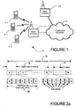
- FIG. 1 schematically illustrates a mobile (cellular) telecommunication system 1 in which a user of a UE (User Equipment, that is a mobile telephone (otherwise referred to as cellular telephones or cell phones) or other device capable of communicating over a mobile (cellular) telecommunication system) 3-0, 3-1, and 3-2 can communicate with a user of another UE (shown or not shown) via one of the base stations 5-1 or 5-2 and a telephone network 7.
- the mobile (cellular) telecommunication system 1 is made up of a number of cells or geographical areas, each of which has a base station 5.
- a UE within a cell may communicate with that cell's base station and UEs may move between neighbouring cells which requires a handover process to hand over communication with the UE from the base station of its current cell (the source base station) to the base station of the cell to which it is moving (the target base station).
- a number of uplink and downlink communications resources are available for the wireless link between the UEs 3 and the base stations 5.
- a base station 5 allocates downlink resources to a UE 3 depending on the amount of data to be sent to the UE 3.
- a base station 5 allocates uplink resources to a UE 3 depending on the amount and type of data that the UE 3 has to send to the base station 5.
- the system bandwidth is divided into five 20 MHz sub-bands, each being carried by a respective component carrier.
- the base station 5 is operable to allocated resources for each UE 3 on one or more of the component carriers, depending on the capability of the UE 3 concerned and the amount of data to be transmitted between the base station 5 and that UE 3.
- the UEs 3 have transceiver circuitry that can receive and transmit signals on the different component carriers and when the UE 3 is not scheduled to use a particular component carrier, it can power down the corresponding transceiver circuitry to conserve battery power.
- an Orthogonal Frequency Division Multiple Access (OFDMA) technique is used for the downlink to allow the UEs 3 to receive data over the air interface with the base station 5.
- OFDMA Orthogonal Frequency Division Multiple Access
- Different sub-carriers are allocated by the base station 5 (for a predetermined amount of time) to each UE 3 depending on the amount of data to be sent to the UE 3.
- PRBs physical resource blocks
- PRBs thus have a time and frequency dimension.
- the base station 5 dynamically allocates PRBs for each device that it is serving and signals the allocations for each sub-frame (TTI) to each of the scheduled UEs 3 in a control channel.
- FIG. 2a illustrates a generic frame structure agreed for LTE Rel 8 communications over the air interface with the base station 5.
- one frame 13 is 10msec (milli-second) long and comprises ten sub-frames 15 of 1msec duration (known as a Transmission Time Interval (TTI)).
- TTI Transmission Time Interval
- Each sub-frame or TTI comprises two slots 17 of 0.5msec duration.
- Each slot 17 comprises either six or seven OFDM symbols 19, depending on whether the normal or extended cyclic prefix (CP) is employed.
- the total number of available sub-carriers depends on the overall transmission bandwidth of the system.
- the LTE specifications define parameters for system bandwidths from 1.4 MHz to 20 MHz and one PRB is currently defined to comprise 12 consecutive subcarriers for one slot 17.
- a PRB over two slots is also defined by the LTE specifications as being the smallest element of resource allocation assigned by the base station scheduler. These sub-carriers are then modulated onto a component carrier to up-convert the signal to the desired transmission bandwidth.
- the transmitted downlink signal thus comprises N BW subcarriers for a duration of N symb OFDM symbols. It can be represented by a resource grid as illustrated in Figure 2b . Each box in the grid represents a single sub-carrier for one symbol period and is referred to as a resource element.
- each PRB 21 is formed from 12 consecutive sub-carriers and (in this case) seven symbols for each subcarrier; although in practice the same allocations are made in the second slot 17 of each sub-frame 15 as well.
- the base station 5 transmits a PDCCH (Physical Downlink Control Channel) over the first three symbols.
- the remaining symbols form the PDSCH (Physical Downlink Shared CHannel) which is used to carry the downlink user data for the UEs 3.
- the PDCCH channel includes, among other things, data for each of the UEs 3, indicating if the UE 3 is scheduled for receiving downlink data in that sub-frame or is scheduled for uplink transmission in that sub-frame; and if so, data identifying the PRBs to be used for receiving the downlink data or for transmitting the uplink data.
- each of the sub-bands will at least be similar in structure to the LTE structure discussed above.
- the sub-carriers for each sub-band will be modulated onto a separate component carrier so that the transmitted sub-bands are contiguous or non-contiguous with each other. This is known as carrier aggregation. If there are five sub-bands each 20 MHz wide, then the total system bandwidth will be 100 MHz. In the following description, the terms sub-band and component carrier will be used interchangeably.
- LTE-Advanced UEs 3 will support bandwidths up to 100 MHz, they may not transmit/receive in the whole spectrum at any given time.
- the system is preferably arranged so that the UEs 3 monitor one or a subset of the component carriers to start with; and then the base station scheduler, based on the activity of the UE 3, can direct the UE 3 to monitor a different (although perhaps overlapping) subset of the component carriers.
- FIG. 3 is a block diagram illustrating the main components of each of the base stations 5 shown in Figure 1 .
- each base station 5 includes transceiver circuitry 31 to transmit signals to and to receive signals from the UEs 3 via one or more antennae 33 and to transmit signals to and to receive signals from the telephone network 7 via a network interface 35.
- a controller 37 is provided to control the operation of the transceiver circuitry 21 in accordance with software stored in memory 39.
- the software includes, among other things, an operating system 41 and a communications control module 43 having a resource allocation module 45 and a scheduler module 47.
- the communications control module 43 is operable to control the generation of the sub-frames in the different sub-bands in which the uplink and downlink data is transmitted from/to the UEs 3.
- the resource allocation module 45 is operable to allocate the resource blocks in the different sub-bands to be used by the transceiver circuitry 31 in its communications with each of the UEs 3, depending on the amount of data to be transmitted between the base station 5 and the UEs 3.
- the scheduler module 47 is operable to schedule the times for the transmission of the downlink data to the UEs 3 and the times for the UE 3 to transmit its uplink data to the base station 5.
- the communications control module 43 is responsible: for signalling, to each of the UEs 3, data identifying which component carriers the UE should be monitoring when in the Idle mode; and for moving the UEs 3 between the different component carriers when in RRC Connected mode; and for defining the DRX patterns used for controlling the times when the UEs 3 can switch off its transceiver circuitry.
- UE User Equipment
- FIG 4 is a block diagram illustrating the main components of each of the UEs 3 shown in Figure 1 .
- the UEs 3 include transceiver circuitry 71 that is operable to transmit signals to and to receive signals from the base station 5 via one or more antennae 73.
- the UE 3 also includes a controller 75 which controls the operation of the UE 3 and which is connected to the transceiver circuitry 71 and to a loudspeaker 77, a microphone 79, a display 81, and a keypad 83.
- the controller 75 operates in accordance with software instructions stored within memory 85.
- these software instructions include, among other things, an operating system 87 and a communications control module 89 that includes a resource allocation module 91 and a transceiver control module 93.
- the communications control module 89 is operable to control communications with the base station 5 and during the Idle mode monitors an anchor component carrier.
- the resource allocation module is responsible for identifying the resources on which uplink should be transmitted and on which downlink data is to be received in the different sub-bands.
- the transceiver control module 93 is responsible for identifying the parts of the transceiver circuitry 71 that can be switched off at the current instance using, for example, DRX configuration data received from the base station 5 or using knowledge of the sub-bands that the UE 3 is to monitor.
- the base stations 5 and the UEs 3 are described for ease of understanding as having a number of discrete modules (such as the resource allocation modules, scheduler module, transceiver control module etc.). Whilst these modules may be provided in this way for certain applications, for example where an existing system has been modified to implement the invention, in other applications, these modules may be built into the overall operating system or code and so these modules may not be discernible as discrete entities.
- LTE-Advanced UEs 3 have transceiver circuitry 71 that can transmit and receive data on a number of different component carriers.
- Figure 5 is a block diagram illustrating suitable transceiver circuitry 71 that may be used.
- the transceiver circuitry includes five up-converter/down-converter circuits 95-1 to 95-5, one for each of the five sub-bands, for modulating and demodulating the sub-carriers onto the corresponding component carrier (C1 to C5).
- the transceiver circuitry 71 also includes five encoding/decoding circuits 97-1 to 97-5 for encoding and decoding the uplink data and downlink data respectively in each of the five sub-bands.
- the encoding/decoding circuits 97 receive the uplink data from, and pass the decoded downlink data to, the controller 75.
- the controller 75 also supplies individual power control signals (via the dashed signal lines) to the encoding/decoding circuits 97 and to the up-converter circuits 95, so that individual circuits can be powered down when not needed and so that they can all be powered down when none of the circuits are needed (for example when the UE 3 enters its sleep mode).
- the communications control module 43 ( Figure 3 ) of the target base station is configured to indicate to the UE which of the multiple component carriers (five in the example above) configured for that UE is to be used by that UE for initial access and the dedicated preamble allocated from that same one of the multiple component carriers, so that, after the handover, the target base station does not have to configure additional component carriers to the UE and does not have to identify to the UE which of the multiple component carriers is to be used for initial access.
- the target base station may provide the Component Carrier Information to a UE by providing the UE with a Component Carrier Index for each of the multiple carrier components configured for that UE.
- the UE and the base station may use these indexes to identify a carrier component, for example while configuring, activating and deactivating one or more of the multiple carrier components.
- These indexes may be stored in a component carrier index store 48 of the communications control module 43 of the base station and a component carrier index store 88 of the communications control module 89 of the UE 3.
- Figure 6 illustrates the proposed intra-MME/Serving Gateway Handover (HO) procedure and shows C- Plane Handover (HO) Signalling with a single carrier where the communications control module 43 ( Figure 3 ) of the target base station is configured to indicate to the UE which of the multiple component carriers configured for that UE is to be used by that UE for initial access.
- the communications control module 43 Figure 3
- the target base station is configured to indicate to the UE which of the multiple component carriers configured for that UE is to be used by that UE for initial access.
- the HO procedure is performed without EPC involvement, i.e. preparation messages are directly exchanged between the eNBs.
- the release of the resources at the source side during the HO completion phase is triggered by the eNB.
- the HANDOVER REQUEST ACKNOWLEDGE message will carry multiple carrier component configuration information and the information on which carrier component to be used for initial access and the dedicate preamble from the same carrier component. This information may use carrier component indexes as discussed above to identify the different carrier components.
- the communications control modules 43 of the base stations 5 are configured to enable Component Carrier Information, for example the indexes mentioned above, to be exchanged between the two base stations during a communications setup or updating procedure, in this example an X2 setup or updating procedure, so that these carrier component indexes can be used be for signaling, for signaling on the X2 and Uu interfaces in this example.
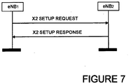
- Figure 7 illustrates a successful operation.
- the purpose of the X2 setup procedure is to exchange application level configuration data needed for two base stations to interoperate correctly over the X2 interface. This procedure erases any existing application level configuration data in the two base stations and replaces it by the one received. This procedure also resets the X2 interface as a Reset procedure would do.
- the procedure uses non UE-associated signalling.
- a base station (eNB1 in Figure 7 ) initiates the X2 setup procedure by sending an X2 SETUP REQUEST message to a candidate base station (eNB2 in Figure 7 ).
- the candidate base station eNB replies with the X2 SETUP RESPONSE message.
- the initiating base station eNB1 transfers a list of served cells and, if available, a list of supported GU Group Ids to the candidate base station eNB2.
- the candidate base station eNB2 replies with a list of its served cells and includes, if available, a list of supported GU Group Ids in the reply.
- the initiating base station eNB 1 may include Neighbour Information IE in the X2 SETUP REQUEST message.
- the candidate base station eNB2 may also include the Neighbour Information IE in the X2 SETUP RESPONSE message.
- the Neighbour Information IE only includes E-UTRAN cells that are direct neighbours of cells in the reporting eNB, where a direct neighbour of one cell of eNB2 may be any cell belonging to an eNB that is a neighbour of that eNB2 cell e.g. even if the cell has not been reported by a UE.
- Component Carrier Information is included in the X2 SETUP REQUEST and X2 SETUP RESPONSE messages and so is exchanged during the X2 setup procedure.
- this Component Carrier Information will be Component Carrier Indexes which can thus be used for signalling on the X2 and Uu interfaces.
- Carrier index information can also be included in X2 ENB CONFIGURATION UPDATE and ENB CONFIGURATION UPDATE ACKNOWLEDGE in case the new carrier is added or existing one deleted.
- a target communications device 5 receiving from a source communications device 5 a notification that a user communications device 3-0, 3-1, 3-2 is to be handed over from that source communications device, provides the source communications device with multiple component carrier information for use by the user communications device.
- the multiple component carrier information includes information indicating to the user communications device which of the multiple component carriers is to be used for initial access.
- the multiple component carrier information may be component carrier indexes.
- Communication devices may exchange component carrier indexes during a setup procedure such as an X2 setup procedure, which indexes can then be used for signalling on the X2 and Uu interfaces.
- the target base station may indicate which, out of the configured component carriers, shall be used by the UE for the initial access by use of component carrier indexes or in another fashion.
- Component Carrier Information may be exchanged by the neighboring base station cells during the setup of the X2 interface between the two base station using Component Carrier Indexes or in another fashion.
- Component Carrier Indexes may be used simply for signaling purpose while configuring, activating and deactivating multiple carrier components.
- the base stations and the UEs can be considered as communications nodes or devices which communicate with each other.
- Other communications nodes or devices may include user devices such as, for example, personal digital assistants, laptop computers, web browsers, etc.
- the software modules may be provided in compiled or un-compiled form and may be supplied to the base station or to the UE as a signal over a computer network, or on a recording medium or may be directly installed or provided as firmware. Further, the functionality provided by part or all of this software may be provided by one or more dedicated hardware circuits or any suitable combination of two or more of software, firmware and hardware. However, the use of software modules is preferred as it facilitates the updating of base station 5 and the UEs 3 in order to update their functionalities. Similarly, although the above embodiments employed transceiver circuitry, at least some of the functionality of the transceiver circuitry may be provided by software or firmware or any suitable combination of two or more of software, firmware and hardware.
- RAN2 discussed the issue of Connected Mode Mobility with Carrier Aggregation for LTE Advance. We had identified that some issues related to the measurement and have requested RAN 4 guidance on these issues. However apart from these issues we have also agreed that it shall be possible at intra-LTE handover to configure multiple CCs in the "handover command" for usage after the handover. In this contribution we focus on the handover signaling and discuss some additional information that would be needed in order to make the initial access in the target cell.
- the target eNB shall not have to configure additional component carriers to the UE after the Handover.
- the Target eNB may first configure only one component carrier for the UE. Subsequently, after the handover, the Target eNB may then configure additional component carriers to the UE. But with the second approach additional signaling would be needed in the target cell.
- target eNB configures multiple carrier component during the handover it is reasonable to assume that the UE will perform initial access in the target cell only on one component carriers in the cell. Moreover when we will have multiple carrier components which are part of a cell we need to allocate dedicated preamble only from one of the component carrier for the UE to perform initial access.
- Proposal 1 For LTE advance we may need the concept of the Component Carrier Index which both the UE and the eNB can use for the signaling purpose while configuring, activating and deactivating multiple carrier components.
- Target eNB When configuring multiple component carriers during handover, Target eNB also needs to indicate which, out of the configured component carrier, shall be used by the UE for the initial access and the dedicate preamble form same component carrier shall be allocated.
- Proposal 3 Component Carrier Information of the neighboring eNB cells is exchanged during the setup of the X2 interface between the two eNB and the carrier component index is known in the neighboring eNB. These carrier component indexes can be used for signaling on X2 and Uu interface.
- Carrier index information can also be included in X2 ENB CONFIGURATION UPDATE and ENB CONFIGURATION UPDATE ACKNOWLEDGE in case the new carrier is added or existing one deleted.
Abstract
Description
- The present invention relates to communications devices, particularly but not exclusively devices operating according to the 3GPP standards or equivalents or derivatives thereof. The invention has particular but not exclusive relevance to the impacts of carrier aggregation that is to be used in LTE-Advanced (Long Term Evolution-Advanced) as currently defined in 3GPP standards documentation TR 36.814.
- With LTE Rel 8, a transmission band of 20MHz was defined. In LTE-Advanced carrier aggregation will be used to support system bandwidths up to 100 MHz. This involves splitting the system bandwidth into five 20 MHz sub-bands, each centred on a respective component carrier. In order to be backwards compatible with LTE Rel 8 User Equipment (UEs), at least one of those sub-bands has to be LTE Rel 8 compliant.
- It has been proposed for LTE-Advanced that, during handover, the target eNB (that is the base station of the cell to which the UE is moving), will tell the UE (via the source eNB, that is the base station of the cell in which the UE is currently located) which Component Carriers (CCs) the UE will be assigned to in the target cell. Thus, it has been proposed that at intra-LTE handover multiple Carrier Components (CCs) will be configured in the handover command for usage after the handover. This is to avoid the need for signalling this information to the UE after it arrives in the target cell so that the target eNB does not have to configure additional Component Carriers to the UE after the handover.
- In one aspect, the present invention provides a communications device that is configured to communicate to a UE which of a plurality of carrier components (CCs) configured in a handover command for usage after the handover should be used for initial access to facilitate initial access of the UE at handover. Dedicated preamble for the UE may be provided from the same component carrier.
- In one aspect, the present invention provides a method performed by a target communications device, the method comprising: receiving from a source communications device a notification that a user communications device is to be handed over from that source communications device; and providing for the user communications device multiple component carrier information including information indicating to the user communications device which of the multiple component carriers is to be used for initial access.
- In another aspect, the present invention provides a method performed by a source communications device, the method comprising: supplying to a target communications device a notification that a user communications device is to be handed over to that target communications device; and receiving from the target communications device multiple component carrier information for the user communications device, the multiple component carrier information including information indicating to the user communications device which of the multiple component carriers is to be used for initial access.
- In another aspect, the present invention provides a method performed by a user communication device, comprising: receiving from a communications device multiple component carrier information including information indicating to the user communications device which of the multiple component carriers is to be used for initial access; and initiating initial access using the identified component carrier.
- In another aspect, the present invention provides a target communications device, the target communications device comprising: a receiver to receive from a source communications device a notification that a user communications device is to be handed over from that source communications device; and a provider to provide for the user communications device multiple component carrier information including information indicating to the user communications device which of the multiple component carriers is to be used for initial access.
- In another aspect, the present invention provides a source communications device, the source communications device comprising: a supplier to supply to a target communications device a notification that a user communications device is to be handed over to that target communications device; and a receiver to receive from the target communications device multiple component carrier information for the user communications device, the multiple component carrier information including information indicating to the user communications device which of the multiple component carriers is to be used for initial access.
- In another aspect, the present invention provides a user communication device, comprising: a receiver to receive from a communications device multiple component carrier information including information indicating to the user communications device which of the multiple component carriers is to be used for initial access; and an initiator to initiate initial access with a target communications device using the identified component carrier.
- The multiple component carrier information may be provided to the source communications device for transmittal to the user communications device.
- In an embodiment, the notification is a handover command. The information indicating which of the multiple component carriers is to be used for initial access by the user communications device may be provided in a handover request acknowledge message to the source communications device for communication to the user communications device. The handover request acknowledge message may include a transparent container to be sent to the user communications device, for example sent as a Radio Resource Control message.
- In an embodiment, the multiple component carrier information indicates that a dedicated preamble is allocated from the component carrier to be used for initial access.
- In an embodiment or embodiments, the component carrier information comprises a component carrier index for each carrier.
- Component carrier information may be exchanged with one or more neighbouring communications devices, for example during a setup or updating procedure such as an X2 interface setup or updating procedure, with that neighbouring communications device.
- The carrier component information may be used for signalling, for example for signalling on the X2 and Uu interfaces.
- In another aspect, the present invention provides a method performed by a target communications device, the method comprising: receiving from a source communications device a notification that a user communications device is to be handed over from that source communications device; and providing for the user communications device multiple component carrier information comprising a component carrier index for each component carrier.
- In another aspect, the present invention provides a method performed by a source communications device, the method comprising: supplying to a target communications device a notification that a user communications device is to be handed over from that source communications device; and receiving for the user communications device multiple component carrier information comprising a component carrier index for each carrier.
- In another aspect, the present invention provides a method performed by a communications device, the method comprising the communications device using carrier components indexes for signalling purposes while at least one of configuring, activating and deactivating multiple carrier components.
- In another aspect, the present invention provides a method performed by a communications device, the method comprising the communications device supplying multiple component carrier information to a neighbouring communications device and receiving multiple component carrier information from a neighbouring communications device during setup or updating of a communication interface such as an X2 interface with that neighbouring communications device.
- In another aspect, the present invention provides a target communications device, the target communications device comprising: a receiver to receive from a source communications device a notification that a user communications device is to be handed over from that source communications device; and a provider to provide for the user communications device multiple component carrier information comprising a component carrier index for each carrier.
- In another aspect, the present invention provides a source communications device, the source communications device comprising: a supplier to supply to a target communications device a notification that a user communications device is to be handed over from that source communications device; and a receiver to receive for the user communications device multiple component carrier information comprising a component carrier index for each carrier.
- In another aspect, the present invention provides a communications device comprising a supplier to supply multiple component carrier information to a neighbouring communications device and a receiver to receive multiple component carrier information from a neighbouring communications device during setup or updating of a communication interface such as an X2 interface with that neighbouring communications device.
- In one aspect, the present invention provides a communications device that provides a component carrier index which both a UE and the communications device can use for the signaling purposes, for example while at least one of configuring, activating and deactivating multiple carrier components.
- In an embodiment, a component carrier index is used to indicate to a UE the component carrier on which the initial access is to be performed in the target cell after handover.
- In one aspect, the present invention provides a communications device that exchanges component carrier information with a neighboring communications device, that is a communications device of a neighboring cell in a cellular network, so that a component carrier index provided to a UE is known also to the neighboring communications device.
- In an embodiment, component carrier information of neighboring communications device is exchanged during the setup or updating of the X2 interface between the two communications devices and the carrier component index is known in the neighboring communications device. These carrier component indexes can be used for signaling on the X2 interface and on the air interface between the UTRAN and the UE (the Uu interface).
- In an embodiment, a target communications device receiving from a source communications device a notification that a user communications device is to be handed over from that source communications device, provides the source communications device with information for multiple component carriers (multiple component carrier information) for use by the user communications device. The multiple component carrier information includes information indicating to the user communications device which of the multiple component carriers is to be used for initial access. The multiple component carrier information may be component carrier indexes. Communication devices may exchange component carrier indexes during a setup or updating procedure such as an X2 setup or updating procedure.
- The invention provides, for all methods disclosed, corresponding computer programs or computer program products for execution on corresponding equipment, the equipment itself (user equipment, communication devices or nodes, or components thereof) and methods of updating the equipment.
- Exemplary embodiments of the invention will now be described, by way of example, with reference to the accompanying drawings, in which:
-
Figure 1 schematically illustrates a mobile telecommunication system of a type to which the invention is applicable; -
Figure 2a schematically illustrates a generic frame structure used in communications over the wireless links of the system shown inFigure 1 ; -
Figure 2b schematically illustrates the way in which the frequency subcarriers are divided into resource blocks and the way that a time slot is divided into a number of OFDM symbols; -
Figure 3 schematically illustrates a base station forming part of the system shown inFigure 1 ; -
Figure 4 schematically illustrates a mobile telephone (UE) forming part of the system shown inFigure 1 ; -
Figure 5 is a block diagram illustrating the main components of transceiver circuitry forming part of the mobile telephone shown inFigure 4 ; -
Figure 6 illustrates one example of a handover process; and -
Figure 7 illustrates an X2 set up procedure. -
Figure 1 schematically illustrates a mobile (cellular)telecommunication system 1 in which a user of a UE (User Equipment, that is a mobile telephone (otherwise referred to as cellular telephones or cell phones) or other device capable of communicating over a mobile (cellular) telecommunication system) 3-0, 3-1, and 3-2 can communicate with a user of another UE (shown or not shown) via one of the base stations 5-1 or 5-2 and atelephone network 7. The mobile (cellular)telecommunication system 1 is made up of a number of cells or geographical areas, each of which has abase station 5. A UE within a cell may communicate with that cell's base station and UEs may move between neighbouring cells which requires a handover process to hand over communication with the UE from the base station of its current cell (the source base station) to the base station of the cell to which it is moving (the target base station). - A number of uplink and downlink communications resources (sub-carriers, time slots etc) are available for the wireless link between the UEs 3 and the
base stations 5. In this embodiment, abase station 5 allocates downlink resources to a UE 3 depending on the amount of data to be sent to the UE 3. Similarly, abase station 5 allocates uplink resources to a UE 3 depending on the amount and type of data that the UE 3 has to send to thebase station 5. - In this embodiment, the system bandwidth is divided into five 20 MHz sub-bands, each being carried by a respective component carrier. The
base station 5 is operable to allocated resources for each UE 3 on one or more of the component carriers, depending on the capability of the UE 3 concerned and the amount of data to be transmitted between thebase station 5 and that UE 3. TheUEs 3 have transceiver circuitry that can receive and transmit signals on the different component carriers and when theUE 3 is not scheduled to use a particular component carrier, it can power down the corresponding transceiver circuitry to conserve battery power. - In the access scheme and general frame structure agreed for LTE Rel 8, an Orthogonal Frequency Division Multiple Access (OFDMA) technique is used for the downlink to allow the
UEs 3 to receive data over the air interface with thebase station 5. Different sub-carriers are allocated by the base station 5 (for a predetermined amount of time) to eachUE 3 depending on the amount of data to be sent to theUE 3. These are referred to as physical resource blocks (PRBs) in the LTE specifications. PRBs thus have a time and frequency dimension. To do this, thebase station 5 dynamically allocates PRBs for each device that it is serving and signals the allocations for each sub-frame (TTI) to each of the scheduledUEs 3 in a control channel. -
Figure 2a illustrates a generic frame structure agreed for LTE Rel 8 communications over the air interface with thebase station 5. As shown, oneframe 13 is 10msec (milli-second) long and comprises ten sub-frames 15 of 1msec duration (known as a Transmission Time Interval (TTI)). Each sub-frame or TTI comprises twoslots 17 of 0.5msec duration. Eachslot 17 comprises either six or sevenOFDM symbols 19, depending on whether the normal or extended cyclic prefix (CP) is employed. The total number of available sub-carriers depends on the overall transmission bandwidth of the system. The LTE specifications define parameters for system bandwidths from 1.4 MHz to 20 MHz and one PRB is currently defined to comprise 12 consecutive subcarriers for oneslot 17. A PRB over two slots is also defined by the LTE specifications as being the smallest element of resource allocation assigned by the base station scheduler. These sub-carriers are then modulated onto a component carrier to up-convert the signal to the desired transmission bandwidth. The transmitted downlink signal thus comprises NBW subcarriers for a duration of Nsymb OFDM symbols. It can be represented by a resource grid as illustrated inFigure 2b . Each box in the grid represents a single sub-carrier for one symbol period and is referred to as a resource element. As shown, eachPRB 21 is formed from 12 consecutive sub-carriers and (in this case) seven symbols for each subcarrier; although in practice the same allocations are made in thesecond slot 17 of each sub-frame 15 as well. - At the start of each sub-frame 15, the
base station 5 transmits a PDCCH (Physical Downlink Control Channel) over the first three symbols. The remaining symbols form the PDSCH (Physical Downlink Shared CHannel) which is used to carry the downlink user data for theUEs 3. The PDCCH channel includes, among other things, data for each of theUEs 3, indicating if theUE 3 is scheduled for receiving downlink data in that sub-frame or is scheduled for uplink transmission in that sub-frame; and if so, data identifying the PRBs to be used for receiving the downlink data or for transmitting the uplink data. - In the proposed LTE-Advanced system, a number of separate sub-bands will be provided in order to support wider transmission bandwidths, each of the sub-bands will at least be similar in structure to the LTE structure discussed above. The sub-carriers for each sub-band will be modulated onto a separate component carrier so that the transmitted sub-bands are contiguous or non-contiguous with each other. This is known as carrier aggregation. If there are five sub-bands each 20 MHz wide, then the total system bandwidth will be 100 MHz. In the following description, the terms sub-band and component carrier will be used interchangeably.
- Although LTE-
Advanced UEs 3 will support bandwidths up to 100 MHz, they may not transmit/receive in the whole spectrum at any given time. In order to allow theUEs 3 to save battery power the system is preferably arranged so that theUEs 3 monitor one or a subset of the component carriers to start with; and then the base station scheduler, based on the activity of theUE 3, can direct theUE 3 to monitor a different (although perhaps overlapping) subset of the component carriers. -
Figure 3 is a block diagram illustrating the main components of each of thebase stations 5 shown inFigure 1 . As shown, eachbase station 5 includestransceiver circuitry 31 to transmit signals to and to receive signals from theUEs 3 via one ormore antennae 33 and to transmit signals to and to receive signals from thetelephone network 7 via anetwork interface 35. Acontroller 37 is provided to control the operation of thetransceiver circuitry 21 in accordance with software stored inmemory 39. The software includes, among other things, anoperating system 41 and acommunications control module 43 having aresource allocation module 45 and ascheduler module 47. Thecommunications control module 43 is operable to control the generation of the sub-frames in the different sub-bands in which the uplink and downlink data is transmitted from/to theUEs 3. Theresource allocation module 45 is operable to allocate the resource blocks in the different sub-bands to be used by thetransceiver circuitry 31 in its communications with each of theUEs 3, depending on the amount of data to be transmitted between thebase station 5 and theUEs 3. Thescheduler module 47 is operable to schedule the times for the transmission of the downlink data to theUEs 3 and the times for theUE 3 to transmit its uplink data to thebase station 5. Thecommunications control module 43 is responsible: for signalling, to each of theUEs 3, data identifying which component carriers the UE should be monitoring when in the Idle mode; and for moving theUEs 3 between the different component carriers when in RRC Connected mode; and for defining the DRX patterns used for controlling the times when theUEs 3 can switch off its transceiver circuitry. -
Figure 4 is a block diagram illustrating the main components of each of theUEs 3 shown inFigure 1 . As shown, theUEs 3 includetransceiver circuitry 71 that is operable to transmit signals to and to receive signals from thebase station 5 via one ormore antennae 73. As shown, theUE 3 also includes acontroller 75 which controls the operation of theUE 3 and which is connected to thetransceiver circuitry 71 and to aloudspeaker 77, amicrophone 79, adisplay 81, and akeypad 83. Thecontroller 75 operates in accordance with software instructions stored withinmemory 85. As shown, these software instructions include, among other things, anoperating system 87 and acommunications control module 89 that includes aresource allocation module 91 and atransceiver control module 93. Thecommunications control module 89 is operable to control communications with thebase station 5 and during the Idle mode monitors an anchor component carrier. The resource allocation module is responsible for identifying the resources on which uplink should be transmitted and on which downlink data is to be received in the different sub-bands. Thetransceiver control module 93 is responsible for identifying the parts of thetransceiver circuitry 71 that can be switched off at the current instance using, for example, DRX configuration data received from thebase station 5 or using knowledge of the sub-bands that theUE 3 is to monitor. - In the above description, the
base stations 5 and theUEs 3 are described for ease of understanding as having a number of discrete modules (such as the resource allocation modules, scheduler module, transceiver control module etc.). Whilst these modules may be provided in this way for certain applications, for example where an existing system has been modified to implement the invention, in other applications, these modules may be built into the overall operating system or code and so these modules may not be discernible as discrete entities. - As mentioned above, LTE-
Advanced UEs 3 havetransceiver circuitry 71 that can transmit and receive data on a number of different component carriers.Figure 5 is a block diagram illustratingsuitable transceiver circuitry 71 that may be used. As shown, the transceiver circuitry includes five up-converter/down-converter circuits 95-1 to 95-5, one for each of the five sub-bands, for modulating and demodulating the sub-carriers onto the corresponding component carrier (C1 to C5). Thetransceiver circuitry 71 also includes five encoding/decoding circuits 97-1 to 97-5 for encoding and decoding the uplink data and downlink data respectively in each of the five sub-bands. The encoding/decoding circuits 97 receive the uplink data from, and pass the decoded downlink data to, thecontroller 75. Thecontroller 75 also supplies individual power control signals (via the dashed signal lines) to the encoding/decoding circuits 97 and to the up-converter circuits 95, so that individual circuits can be powered down when not needed and so that they can all be powered down when none of the circuits are needed (for example when theUE 3 enters its sleep mode). - The communications control module 43 (
Figure 3 ) of the target base station is configured to indicate to the UE which of the multiple component carriers (five in the example above) configured for that UE is to be used by that UE for initial access and the dedicated preamble allocated from that same one of the multiple component carriers, so that, after the handover, the target base station does not have to configure additional component carriers to the UE and does not have to identify to the UE which of the multiple component carriers is to be used for initial access. - In an example, the target base station may provide the Component Carrier Information to a UE by providing the UE with a Component Carrier Index for each of the multiple carrier components configured for that UE. The UE and the base station may use these indexes to identify a carrier component, for example while configuring, activating and deactivating one or more of the multiple carrier components. These indexes may be stored in a component
carrier index store 48 of thecommunications control module 43 of the base station and a componentcarrier index store 88 of thecommunications control module 89 of theUE 3. -
Figure 6 illustrates the proposed intra-MME/Serving Gateway Handover (HO) procedure and shows C- Plane Handover (HO) Signalling with a single carrier where the communications control module 43 (Figure 3 ) of the target base station is configured to indicate to the UE which of the multiple component carriers configured for that UE is to be used by that UE for initial access. - The HO procedure is performed without EPC involvement, i.e. preparation messages are directly exchanged between the eNBs. The release of the resources at the source side during the HO completion phase is triggered by the eNB.
- 0 The UE context within the source eNB (eNodeB) contains information regarding roaming restrictions which were provided either at connection establishment or at the last TA update.
- 1 The source eNB configures the UE measurement procedures according to the area restriction information. Measurements provided by the source eNB may assist the function controlling the UE's connection mobility.
- 2 UE is triggered to send MEASUREMENT REPORT by the rules set by i.e. system information, specification etc.
- 3 Source eNB makes a decision based on MEASUREMENT REPORT and RRM information to hand off UE.
- 4 The source eNB issues a HANDOVER REQUEST message to the target eNB passing necessary information to prepare the HO at the target side (UE X2 signalling context reference at source eNB,
UE S 1 EPC signalling context reference, target cell ID, KeNB*, RRC context including the C-RNTI of the UE in the source eNB, AS-configuration, E-RAB context and physical layer ID of the source cell + MAC for possible RLF recovery). UE X2 / UE S1 signalling references enable the target eNB to address the source eNB and the EPC. The E-RAB context includes necessary RNL and TNL addressing information, and QoS profiles of the E-RABs. - 5 Admission Control may be performed by the target eNB dependent on the received E-RAB QoS information to increase the likelihood of a successful HO, if the resources can be granted by target eNB. The target eNB configures the required resources according to the received E-RAB QoS information and reserves a C-RNTI and optionally a RACH preamble. The AS-configuration to be used in the target cell can either be specified independently (i.e. an "establishment") or as a delta compared to the AS-configuration used in the source cell (i.e. a "reconfiguration").
- 6 Target eNB prepares HO with L1/L2 and sends the HANDOVER REQUEST ACKNOWLEDGE to the source eNB. The HANDOVER REQUEST ACKNOWLEDGE message includes a transparent container to be sent to the UE as an RRC message to perform the handover. The container includes a new C-RNTI, target eNB security algorithm identifiers for the selected security algorithms, may include a dedicated RACH preamble, and possibly some other parameters i.e. access parameters, SIBs, etc. For LTE Advanced, this message will carry multiple carrier configuration information and the information on which carrier to be used for initial access and the dedicate preamble from the same carrier. The HANDOVER REQUEST ACKNOWLEDGE message may also include RNL/TNL information for the forwarding tunnels, if necessary. NOTE: As soon as the source eNB receives the HANDOVER REQUEST ACKNOWLEDGE, or as soon as the transmission of the handover command is initiated in the downlink, data forwarding may be initiated.
Steps 7 to 16 provide means to avoid data loss during HO and are further detailed in 10.1.2.1.2 and 10.1.2.3 of the 3GPP Specifications 36.300 EUTRANOverall Description Stage 2. - 7 The target eNB generates the RRC message to perform the handover, i.e RRC Connection Reconfiguration message including the mobilityControl Information, to be sent by the source eNB towards the UE. The source eNB performs the necessary integrity protection and ciphering of the message. The UE receives the RRC Connection Reconfiguration message with necessary parameters (i.e. new C-RNTI, target eNB security algorithm identifiers, and optionally dedicated RACH preamble, target eNB SIBs, etc.) and is commanded by the source eNB to perform the HO. The UE does not need to delay the handover execution for delivering the HARQ/ARQ responses to source eNB.
- 8 The source eNB sends the SN STATUS TRANSFER message to the target eNB to convey the uplink PDCP SN receiver status and the downlink PDCP SN transmitter status of E-RABs for which PDCP status preservation applies (i.e. for RLC AM). The uplink PDCP SN receiver status includes at least the PDCP SN of the first missing UL SDU and may include a bit map of the receive status of the out of sequence UL SDUs that the UE needs to retransmit in the target cell, if there are any such SDUs. The downlink PDCP SN transmitter status indicates the next PDCP SN that the target eNB shall assign to new SDUs, not having a PDCP SN yet. The source eNB may omit sending this message if none of the E-RABs of the UE shall be treated with PDCP status preservation.
- 9 After receiving the RRC Connection Reconfiguration message including the mobilityControl Information, UE performs synchronisation to target eNB and accesses the target cell via RACH, following a contention-free procedure if a dedicated RACH preamble was indicated in the mobility Control Information, or following a contention-based procedure if no dedicated preamble was indicated. UE derives target eNB specific keys and configures the selected security algorithms to be used in the target cell.
- 10 The target eNB responds with UL allocation and timing advance.
- 11 When the UE has successfully accessed the target cell, the UE sends the RRC Connection Reconfiguration Complete message (C-RNTI) to confirm the handover, along with an uplink Buffer Status Report, whenever possible, to the target eNB to indicate that the handover procedure is completed for the UE. The target eNB verifies the C-RNTI sent in the RRC Connection Reconfiguration Complete message. The target eNB can now begin sending data to the UE.
- 12 The target eNB sends a PATH SWITCH message to MME to inform that the UE has changed cell.
- 13 The MME sends an UPDATE USER PLANE REQUEST message to the Serving Gateway.
- 14 The Serving Gateway switches the downlink data path to the target side. The Serving Gateway sends one or more "end marker" packets on the old path to the source eNB and then can release any U-plane/TNL resources towards the source eNB.
- 15 Serving Gateway sends an UPDATE USER PLANE RESPONSE message to MME.
- 16 The MME confirms the PATH SWITCH message with the PATH SWITCH ACKNOWLEDGE message.
- 17 By sending UE CONTEXT RELEASE, the target eNB informs success of HO to source eNB and triggers the release of resources by the source eNB. The target eNB sends this message after the PATH SWITCH ACKNOWLEDGE message is received from the MME.
- 18 Upon reception of the UE CONTEXT RELEASE message, the source eNB can release radio and C-plane related resources associated to the UE context. Any ongoing data forwarding may continue.
- As set out above, for LTE Advanced, the HANDOVER REQUEST ACKNOWLEDGE message will carry multiple carrier component configuration information and the information on which carrier component to be used for initial access and the dedicate preamble from the same carrier component. This information may use carrier component indexes as discussed above to identify the different carrier components.
- In an example, the
communications control modules 43 of thebase stations 5 are configured to enable Component Carrier Information, for example the indexes mentioned above, to be exchanged between the two base stations during a communications setup or updating procedure, in this example an X2 setup or updating procedure, so that these carrier component indexes can be used be for signaling, for signaling on the X2 and Uu interfaces in this example.Figure 7 illustrates a successful operation. - The X2 setup procedure is described in sections 8.3.3.1 and 8.3.3.2 of 36.423 of the 3GPP Specifications.
Figure 7 illustrates a successful setup procedure. - The purpose of the X2 setup procedure is to exchange application level configuration data needed for two base stations to interoperate correctly over the X2 interface. This procedure erases any existing application level configuration data in the two base stations and replaces it by the one received. This procedure also resets the X2 interface as a Reset procedure would do. The procedure uses non UE-associated signalling.
- Thus, in this setup procedure, a base station (eNB1 in
Figure 7 ) initiates the X2 setup procedure by sending an X2 SETUP REQUEST message to a candidate base station (eNB2 inFigure 7 ). The candidate base station eNB replies with the X2 SETUP RESPONSE message. The initiating base station eNB1 transfers a list of served cells and, if available, a list of supported GU Group Ids to the candidate base station eNB2. The candidate base station eNB2 replies with a list of its served cells and includes, if available, a list of supported GU Group Ids in the reply. - The initiating
base station eNB 1 may include Neighbour Information IE in the X2 SETUP REQUEST message. The candidate base station eNB2 may also include the Neighbour Information IE in the X2 SETUP RESPONSE message. The Neighbour Information IE only includes E-UTRAN cells that are direct neighbours of cells in the reporting eNB, where a direct neighbour of one cell of eNB2 may be any cell belonging to an eNB that is a neighbour of that eNB2 cell e.g. even if the cell has not been reported by a UE. - In this example, Component Carrier Information is included in the X2 SETUP REQUEST and X2 SETUP RESPONSE messages and so is exchanged during the X2 setup procedure. Generally this Component Carrier Information will be Component Carrier Indexes which can thus be used for signalling on the X2 and Uu interfaces.
- Carrier index information can also be included in X2 ENB CONFIGURATION UPDATE and ENB CONFIGURATION UPDATE ACKNOWLEDGE in case the new carrier is added or existing one deleted.
- In an embodiment, a
target communications device 5 receiving from a source communications device 5 a notification that a user communications device 3-0, 3-1, 3-2 is to be handed over from that source communications device, provides the source communications device with multiple component carrier information for use by the user communications device. The multiple component carrier information includes information indicating to the user communications device which of the multiple component carriers is to be used for initial access. The multiple component carrier information may be component carrier indexes. Communication devices may exchange component carrier indexes during a setup procedure such as an X2 setup procedure, which indexes can then be used for signalling on the X2 and Uu interfaces. - As those skilled in the art will appreciate, a number of modifications and alternatives can be made to the above-described embodiments whilst still benefiting from the inventions embodied therein. By way of illustration only a number of these alternatives and modifications will now be described. These alternatives and modifications may be used alone or in any combination.
- The examples described above indicate that there are five carrier components for LTE-Advanced. It will of course be appreciated that this is for compliance with LTE-Advanced and that the number of carrier components could be fewer or less. The features described above may be used alone or in combination. Thus, for example the target base station may indicate which, out of the configured component carriers, shall be used by the UE for the initial access by use of component carrier indexes or in another fashion. Component Carrier Information may be exchanged by the neighboring base station cells during the setup of the X2 interface between the two base station using Component Carrier Indexes or in another fashion. Component Carrier Indexes may be used simply for signaling purpose while configuring, activating and deactivating multiple carrier components.
- In the above embodiments, a telephone based telecommunications system was described. As those skilled in the art will appreciate, the signalling and power control techniques described in the present application can be employed in any communications system. In the general case, the base stations and the UEs can be considered as communications nodes or devices which communicate with each other. Other communications nodes or devices may include user devices such as, for example, personal digital assistants, laptop computers, web browsers, etc.
- In the above embodiments, a number of software modules were described. As those skilled will appreciate, the software modules may be provided in compiled or un-compiled form and may be supplied to the base station or to the UE as a signal over a computer network, or on a recording medium or may be directly installed or provided as firmware. Further, the functionality provided by part or all of this software may be provided by one or more dedicated hardware circuits or any suitable combination of two or more of software, firmware and hardware. However, the use of software modules is preferred as it facilitates the updating of
base station 5 and theUEs 3 in order to update their functionalities. Similarly, although the above embodiments employed transceiver circuitry, at least some of the functionality of the transceiver circuitry may be provided by software or firmware or any suitable combination of two or more of software, firmware and hardware. - Various other modifications will be apparent to those skilled in the art and will not be described in further detail here.
-
- LTE - Long Term Evolution (of UTRAN)
- eNodeB - E-UTRAN Node B
- UE - User Equipment - mobile communication device
- DL - downlink - link from base to mobile
- UL - uplink - link from mobile to base
- MME - Mobility Management Entity
- UPE- User Plane Entity
- HO - Handover
- RLC - Radio Link Control
- RRC - Radio Resource Control
- RRM - Radio Resource Management
- SAE - System Architecture Evolution
- C-RNTI - Cell-Radio Network Temporary Identifier
- SIB - System Information Block
- U-plane - User Plane
- X2 Interface - Interface between two eNodeB
- S1 Interface - Interface between eNodeB and MME
- TA - Tracking Area
- EPC - Evolved Packet Core
- AS - Access Stratum
- RNL - Radio Network Layer
- TNL - Transport Network Layer
- RACH - Random Access Channel
- MU MIMO - Multi-User Multi Input Multi Output
- DMRS - Demodulation Reference Signal Format
- MCS - Modulation and Coding Scheme
- E-RAB - Evolved Radio Access Bearer
- PDCP-SN - Packet Data Convergence Protocol Sequence Number
- RLC AM - Radio Link Control Acknowledge Mode
- UL SDU - UpLink Service Data Unit
- X2 ENB - X2 eNodeB
- The following is a detailed description of the way in which the present inventions may be implemented in the currently proposed 3GPP standard. Whilst various features are described as being essential or necessary, this may only be the case for the proposed 3GPP standard, for example due to other requirements imposed by the standard. These statements should not, therefore, be construed as limiting the present invention in any way.
- At the
RAN 2 #66 bis meeting in Los Angeles, RAN2 discussed the issue of Connected Mode Mobility with Carrier Aggregation for LTE Advance. We had identified that some issues related to the measurement and have requestedRAN 4 guidance on these issues. However apart from these issues we have also agreed that it shall be possible at intra-LTE handover to configure multiple CCs in the "handover command" for usage after the handover. In this contribution we focus on the handover signaling and discuss some additional information that would be needed in order to make the initial access in the target cell. - We have agreed that it shall be possible at intra-LTE handover to configure multiple CCs in the handover command for usage after the handover. We see that there are benefits of this approach as the target eNB shall not have to configure additional component carriers to the UE after the Handover. Although one may argue that the Target eNB may first configure only one component carrier for the UE. Subsequently, after the handover, the Target eNB may then configure additional component carriers to the UE. But with the second approach additional signaling would be needed in the target cell.
- In the first approach where target eNB configures multiple carrier component during the handover it is reasonable to assume that the UE will perform initial access in the target cell only on one component carriers in the cell. Moreover when we will have multiple carrier components which are part of a cell we need to allocate dedicated preamble only from one of the component carrier for the UE to perform initial access.
- For LTE advance we will probably need the concept of the Component Carrier Index which both the UE and the eNB can use for the signaling purpose while configuring, activating and deactivating multiple carrier components and also for indicating the component carrier on which the initial access is to be performed in the target cell after handover.
- Proposal 1: For LTE advance we may need the concept of the Component Carrier Index which both the UE and the eNB can use for the signaling purpose while configuring, activating and deactivating multiple carrier components.
- Proposal 2: When configuring multiple component carriers during handover, Target eNB also needs to indicate which, out of the configured component carrier, shall be used by the UE for the initial access and the dedicate preamble form same component carrier shall be allocated.
- Further it is reasonable to assume that the Component Carrier Information of the neighboring eNB cells is exchanged during the setup of the X2 interface between the two eNB and the carrier component index are known in the neighboring eNB. Although this is a
RAN 3 issue, but if we agree inRAN 2 to use this kind of approach it would be good to liaise withRAN 3 to have consistent definition on the Uu and X2 interface for the carrier component index. - Proposal 3: Component Carrier Information of the neighboring eNB cells is exchanged during the setup of the X2 interface between the two eNB and the carrier component index is known in the neighboring eNB. These carrier component indexes can be used for signaling on X2 and Uu interface.
- Carrier index information can also be included in X2 ENB CONFIGURATION UPDATE and ENB CONFIGURATION UPDATE ACKNOWLEDGE in case the new carrier is added or existing one deleted.
- In this paper we discuss what additional signaling details would be needed while configuring multiple component carriers during connected mode mobility and also for the details of how the UE connected mode be assigned to monitor a subset of carriers. The main proposals of the contribution are
- Proposal 1: For LTE advance we may need the concept of the Component Carrier Index which both the UE and the eNB can use for the signaling purpose while configuring, activating and deactivating multiple carrier components.
- Proposal 2: When configuring multiple component carriers during handover, Target eNB also needs to indicate which, out of the configured component carrier, shall be used by the UE for the initial access and the dedicate preamble form same component carrier shall be allocated.
- Proposal 3: Component Carrier Information of the neighboring eNB cells is exchanged during the setup of the X2 interface between the two eNB and the carrier component index is known in the neighboring eNB. These carrier component indexes can be used for signaling on X2 and Uu interface.
- Carrier index information can also be included in X2 ENB CONFIGURATION UPDATE and ENB CONFIGURATION UPDATE ACKNOWLEDGE in case the new carrier is added or existing one deleted.
- While this invention has been described in terms of the embodiment, this invention is not limited thereto. The structure and details of this invention can be applied with various changes that can be understood by a person skilled in the art within the sprit and scope of this invention described in the claims.
- This application is based upon and claims the benefit of priority from United Kingdom Patent Application No.
0914353.8, filed on August 17, 2009 - Exemplary embodiments of the invention are set out in the following numbered clauses:
- 1. A method performed by a target communications device, the method comprising:
- receiving from a source communications device a notification that a user communications device is to be handed over from that source communications device; and
- providing for the user communications device multiple component carrier information including information to indicate to the user communications device which of the multiple component carriers is to be used for initial access.
- 2. A method according to
Clause 1, wherein the multiple component carrier information is provided to the source communications device for transmittal to the user communications device. - 3. A method according to
Clause 1, wherein the notification received from the source communications device is a handover command. - 4. A method according to
Clause 1, wherein the notification received from the source communications device is a handover command and the information indicating which of the multiple component carriers is to be used for initial access by the user communications device is provided in a handover request acknowledge message to the source communications device for communication to the user communications device. - 5. A method according to
Clause 4, wherein the handover request acknowledge message includes a transparent container to be sent to the user communications device. - 6. A method according to
Clause 4, wherein the handover request acknowledge message includes a transparent container to be sent to the user communications device as a Radio Resource Control message. - 7. A method according to any one of
Clauses 1 to 6, wherein the multiple component carrier information indicates that a dedicated preamble is allocated from the component carrier to be used for initial access. - 8. A method performed by a source communications device, the method comprising:
- supplying to a target communications device a notification that a user communications device is to be handed over to that target communications device; and
- receiving from the target communications device multiple component carrier information for the user communications device, the multiple component carrier information including information to indicate to the user communications device which of the multiple component carriers is to be used for initial access.
- 9. A method according to Clause 8, wherein the notification received from a source communications device is a handover command.
- 10. A method according to Clause 8, wherein the notification is a handover command and the information indicating which of the multiple component carriers is to be used for initial access by the user communications device is received in a handover request acknowledge message from the target communications device to the source communications device for communication to the user communications device.
- 11. A method according to
Clause 10, further comprising communicating to the user communications device a transparent container included in the handover request acknowledge message. - 12. A method according to
Clause 11, wherein the transport container is sent to the user communications device as a Radio Resource Control message. - 13. A method according to any one of Clauses 8 to 12, wherein the multiple component carrier information indicates that a dedicated preamble is allocated from the component carrier to be used for initial access.
- 14. A method according to any one of
Clauses 1 to 13, wherein the component carrier information comprises a component carrier index for each carrier. - 15. A method according to any one of
Clauses 1 to 14, further comprising exchanging component carrier information with one or more neighbouring communications devices. - 16. A method according to any one of
Clauses 1 to 14, wherein the method further comprises exchanging component carrier information with a neighbouring communications device during setup or updating of a communications interface with that neighbouring communications device. - 17. A method according to any one of
Clauses 1 to 13, wherein the component carrier information comprises a component carrier index for each carrier and the method further comprises exchanging component carrier indexes with a neighbouring communications device during setup or updating of an X2 interface with that neighbouring communications device. - 18. A method according to
Clause - 19. A method according to
Clause 17, further comprising using the carrier component indexes for signalling on the X2 and Uu interfaces. - 20. A method performed by a user communication device, comprising:
- receiving from a communications device multiple component carrier information including information indicating to the user communications device which of the multiple component carriers is to be used for initial access; and
- initiating initial access with a target communications device using the identified component carrier.
- 21. A method according to Clause 20, wherein the multiple component carrier information is received in a transparent container included in the handover request acknowledge message.
- 22. A method according to
Clause 21, wherein the transparent container is received as a Radio Resource Control message. - 23. A method according to any one of Clauses 20 to 22, wherein the component carrier information comprises a component carrier index for each carrier.
- 24. A method performed by a target communications device, the method comprising:
- receiving from a source communications device a notification that a user communications device is to be handed over from that source communications device; and
- providing for the user communications device multiple component carrier information comprising a component carrier index for each carrier.
- 25. A method performed by a source communications device, the method comprising:
- supplying to a target communications device a notification that a user communications device is to be handed over from that source communications device; and
- receiving for the user communications device multiple component carrier information comprising a component carrier index for each carrier.
- 26. A method according to Clause 25, further comprising communicating the multiple component carrier information to the user communications device.
- 27. A method according to Clause 24, 25 or 26, further comprising exchanging component carrier information with one or more neighbouring communications devices.
- 28. A method performed by a communications device, the method comprising the communications device using carrier components indexes for signalling purposes while at least one of configuring, activating and deactivating multiple carrier components.
- 29. A method performed by a communications device, the method comprising the communications device supplying multiple component carrier information to a neighbouring communications device and receiving multiple component carrier information from a neighbouring communications device during setup of or updating of a communications interface with that neighbouring communications device.
- 30. A method according to Clause 29, further comprising using the carrier component information for signalling.
- 31. A method according to Clause 29, wherein the carrier component information comprises carrier component indexes and the method further comprises using the carrier component indexes for signalling on the X2 and Uu interfaces.
- 32. A target communications device comprising:
- a receiver to receive from a source communications device a notification that a user communications device is to be handed over from that source communications device; and
- a provider to provide for the user communications device multiple component carrier information including information indicating to the user communications device which of the multiple component carriers is to be used for initial access.
- 33. A communications device according to Clause 32, wherein the provider is operable to provide the multiple component carrier information including information indicating to the user communications device which of the multiple component carriers is to be used for initial access to the source communications device for transmittal to the user communications device.
- 34. A communications device according to Clause 32, wherein the notification received from the source communications device is a handover command.
- 35. A communications device according to Clause 32, wherein the notification received from a source communications device is a handover command and the provider is operable to provide the information indicating which of the multiple component carriers is to be used for initial access by the user communications device in a handover request acknowledge message to the source communications device for communication to the user communications device.
- 36. A communications device according to
Clause 35, wherein the handover request acknowledge message includes a transparent container to be sent to the user communications device. - 37. A communications device according to
Clause 35, wherein the handover request acknowledge message includes a transparent container to be sent to the user communications device as a Radio Resource Control message. - 38. A communications device according to any one of Clauses 32 to 37, wherein the provider is operable to provide information in the multiple component carrier information that indicates that a dedicated preamble is allocated from the component carrier to be used for initial access.
- 39. A source communications device comprising:
- a supplier to supply to a target communications device a notification that a user communications device is to be handed over to that target communications device; and
- a receiver to receive from the target communications device multiple component carrier information for the user communications device, the multiple component carrier information including information indicating to the user communications device which of the multiple component carriers is to be used for initial access.
- 40. A communications device according to
Clause 39, wherein the notification received from a source communications device is a handover command. - 41. A communications device according to
Clause 39, wherein the notification is a handover command and the information indicating which of the multiple component carriers is to be used for initial access by the user communications device is received in a handover request acknowledge message from the target communications device to the source communications device for communication to the user communications device. - 42. A communications device according to
Clause 41, further comprising a user device communicator to communicate to the user communications device a transparent container included in the handover request acknowledge message. - 43. A communications device according to Clause 42, wherein the user device communicator is operable to send the transparent container to the user communications device as a Radio Resource Control message.
- 44. A communications device according to any one of
Clause 39 to 43, wherein the multiple component carrier information indicates that a dedicated preamble is allocated from the component carrier to be used for initial access. - 45. A communications device according to any one of Clauses 32 to 44, wherein the component carrier information comprises a component carrier index for each carrier.
- 46. A communications device according to any one of Clauses 32 to 45, further comprising a communications device communicator to exchange component carrier information with one or more neighbouring communications devices.
- 47. A communications device according to any one of Clauses 32 to 45, further comprising a communications device communicator to exchange component carrier information with a neighbouring communications device during setup of or updating of a communications interface with that neighbouring communications device.
- 48. A communications device according to any one of Clauses 32 to 44, wherein the component carrier information comprises a component carrier index for each carrier and the communications device further comprises a communications device communicator to exchange component carrier indexes with a neighbouring communications device during setup of or updating of a communications interface with that neighbouring communications device.
- 49. A communications device according to
Clause - 50. A communications device according to
Clause 48, wherein the carrier component information comprises indexes and the communicator is operable to use the carrier component indexes for signalling on the X2 and Uu interfaces. - 51. A user communication device comprising:
- a receiver to receive from a communications device multiple component carrier information including information indicating to the user communications device which of the multiple component carriers is to be used for initial access; and
- an initiator to initiate initial access with a target communications device using the identified component carrier.
- 52. A communications device according to Clause 51, wherein the receiver is operable to receive the multiple component carrier information in a transparent container included in the handover request acknowledge message.
- 53. A communications device according to Clause 52, wherein the transparent container is received as a Radio Resource Control message.
- 54. A communications device according to any one of Clauses 51 to 53, wherein the component carrier information comprises a component carrier index for each carrier.
- 55. A target communications device comprising:
- a receiver to receive from a source communications device a notification that a user communications device is to be handed over from that source communications device; and
- a provider to provide for the user communications device multiple component carrier information comprising a component carrier index for each carrier.
- 56. A source communications device comprising:
- a supplier to supply to a target communications device a notification that a user communications device is to be handed over from that source communications device; and
- a receiver to receive for the user communications device multiple component carrier information comprising a component carrier index for each carrier.
- 57. A communications device according to Clause 56, further comprising a user device communicator to communicate the multiple component carrier information to the user communications device.
- 58. A communications device according to Clause 55, 56, 57, further comprising a communications device communicator to exchange component carrier information with one or more neighbouring communications devices.
- 59. A communications device comprising a communicator configured to use carrier components indexes for signalling purposes while at least one of configuring, activating and deactivating multiple carrier components.
- 60. A communications device comprising a supplier to supply multiple component carrier information to a neighbouring communications device and a receiver to receive multiple component carrier information from a neighbouring communications device during setup of or updating of a communications interface with that neighbouring communications device.
- 61. A communications device according to Clause 60, further comprising a communcations communicator that uses the carrier component information for signalling purposes.
- 62. A communications device according to Clause 60, further comprising a communication communicator that uses the carrier component indexes for signalling on the X2 and Uu interfaces.
- 63. A target communications device comprising:
- receiving means for receiving from a source communications device a notification that a user communications device is to be handed over from that source communications device; and
- providing means for providing for the user communications device multiple component carrier information including information indicating to the user communications device which of the multiple component carriers is to be used for initial access.
- 64. A source communications device comprising:
- supplying means for supplying to a target communications device a notification that a user communications device is to be handed over to that target communications device; and
- receiving means for receiving from the target communications device multiple component carrier information for the user communications device, the multiple component carrier information including information indicating to the user communications device which of the multiple component carriers is to be used for initial access.
- 65. A user communication device comprising:
- receiving means for receiving from a communications device multiple component carrier information including information indicating to the user communications device which of the multiple component carriers is to be used for initial access; and
- initiating means for initiating initial access with a target communications device using the identified component carrier.
- 66. A target communications device comprising:
- receiving means for receiving from a source communications device a notification that a user communications device is to be handed over from that source communications device; and
- providing means for providing for the user communications device multiple component carrier information comprising a component carrier index for each carrier.
- 67. A source communications device comprising:
- supplying means for supplying to a target communications device a notification that a user communications device is to be handed over from that source communications device; and
- receiving means for receiving for the user communications device multiple component carrier information comprising a component carrier index for each carrier.
- 68. A communications device comprising communicating means for using carrier components indexes for signalling purposes while at least one of configuring, activating and deactivating multiple carrier components.
- 69. A communications device comprising supplying means for supplying multiple component carrier information to a neighbouring communications device and receiving means for receiving multiple component carrier information from a neighbouring communications device during setup of or updating of a communications interface with that neighbouring communications device.
- 70. A method according to
Clause 16 or 29, wherein the setup or updating procedure is an X2 setup or updating procedure. - 71. A device according to any one of
Clauses - 72. A computer program product comprising computer implementable instructions for causing a programmable computer device to carry out a method in accordance with any one of
Clauses 1 to 31 and 70.
Claims (7)
- A method performed by a source communications device (5), the method comprising:configuring measurement procedures for a user communications device (3);receiving a measurement report from the user communications device (3);making a decision, based on the measurement report received from the user communications device (3), to hand off the user communications device (3);sending, to a target communications device (5), a handover request message comprising a C-RNTI of the user communications device (3) to be handed over to that target communications device (5), an Access Stratum, AS, configuration, Evolved Radio Access Bearer, E-RAB, context and physical layer identity of a cell operated by the source communications device; andreceiving, from the target communications device (5), first information comprising at least one component carrier index for identifying at least one component carrier of multiple component carriers and second information for indicating to the user communications device (3) which of the multiple component carriers is to be used for initial access;wherein the first information and the second information are included in a handover request acknowledge message sent by the target communications device (5), responsive to the handover request message received from the source communications device (5), for communication to the user communications device; andwherein the first information and the second information are included in an RRC Connection Reconfiguration message to be sent to the user communications device (3);further comprising communicating, to the user communications device (3), the RRC Connection Reconfiguration message including the first information and the second information.
- A method performed by a target communications device (5), the method comprising:receiving from a source communications device (5) a handover request message comprising a C-RNTI of a user communications device (3) to be handed over from that source communications device (5), an Access Stratum, AS, configuration, Evolved Radio Access Bearer, E-RAB, context and physical layer identity of a cell operated by the source communications device; andproviding for the user communications device (3) first information comprising at least one component carrier index for identifying at least one component carrier of multiple component carriers and second information for indicating to the user communications device (3) which of the multiple component carriers is to be used for initial access; andwherein the first information and the second information are included in a handover request acknowledge message sent to the source communications device (5), responsive to the handover request message received from the source communications device (5), for communication to the user communications device.
- A method performed by a user communications device (3), comprising:performing measurement procedures configured by a source communications device (5);sending a measurement report to the source communications device (5);receiving from the source communications device (5) first information comprising at least one component carrier index for identifying at least one component carrier of multiple component carriers and second information for indicating to the user communications device (3) which of the multiple component carriers is to be used for initial access;wherein the first information and second information are included in an RRC Connection Reconfiguration message; andinitiating initial access with a target communications device (5) using the indicated component carrier.
- A source communications device (5) comprising:means for configuring measurement procedures for a user communications device (3);means for receiving a measurement report from the user communications device (3);means for making a decision, based on the measurement report received from the user communications device (3), to hand off the user communications device (3);means for sending, to a target communications device (5), a handover request message comprising a C-RNTI of the user communications device (3) to be handed over to that target communications device (5), an Access Stratum, AS, configuration, Evolved Radio Access Bearer, E-RAB, context and physical layer identity of a cell operated by the source communications device; andreceiving means for receiving from the target communications device (5) first information comprising at least one component carrier index for identifying at least one component carrier of the multiple component carriers and second information for indicating to the user communications device (3) which of the multiple component carriers is to be used for initial access;wherein the first information and the second information are included in a handover request acknowledge message sent by the target communications device (5), responsive to the handover request message received from the source communications device (5), for communication to the user communications device; andwherein the first information and the second information are included in an RRC Connection Reconfiguration message adapted to be sent to the user communications device (3);further comprising a user device communicating means to communicate to the user communications device (3), the RRC Connection Reconfiguration message including the first information and the second information.
- A target communications device (5) of a communication system that uses multiple component carriers, the target communications (5) device comprising:receiving means for receiving from a source communications device (5) a handover request message comprising a C-RNTI of a user communications device (3) to be handed over from that source communications device (5), an Access Stratum, AS, configuration, Evolved Radio Access Bearer, E-RAB, context and physical layer identity of a cell operated by the source communications device; andproviding means for providing for the user communications device (3) first information comprising component at least one carrier index for identifying at least one component carrier of multiple component carriers and second information for indicating to the user communications device (3) which of the multiple component carriers is to be used for initial access; andwherein the first information and the second information are included in a handover request acknowledge message sent to the source communications device (5), responsive to the handover request message received from the source communications device (5), for communication to the user communications device.
- A user communications device (3) comprising:means for performing measurement procedures configured by a source communications device (5);means for sending a measurement report to the source communications device (5);means for receiving from the source communications device (5) first information comprising at least one component carrier index for identifying at least one component carrier of the multiple component carriers and second information for indicating to the user communications device (3) which of the multiple component carriers is to be used for initial access;wherein the first information and second information are included in an RRC Connection Reconfiguration message; andinitiating means for initiating initial access with a target communications device (5) using the indicated component carrier.
- A computer program product comprising computer implementable instructions for causing a programmable computer device to carry out a method in accordance with any one of Claims 1 to 3, when executed by the programmable computer device.
Applications Claiming Priority (5)
| Application Number | Priority Date | Filing Date | Title |
|---|---|---|---|
| GB0914353A GB2472789A (en) | 2009-08-17 | 2009-08-17 | In a lte-advanced network a target enb sends a source enb information to indicate to the ue which of multiple component carriers is to be used for initail acc |
| EP10747697.0A EP2468039B1 (en) | 2009-08-17 | 2010-08-10 | Communications system |
| PCT/JP2010/063794 WO2011021595A1 (en) | 2009-08-17 | 2010-08-10 | Communications system |
| EP17154706.0A EP3182756B1 (en) | 2009-08-17 | 2010-08-10 | Communications systems |
| EP16150688.6A EP3029990B1 (en) | 2009-08-17 | 2010-08-10 | Communications systems |
Related Parent Applications (4)
| Application Number | Title | Priority Date | Filing Date |
|---|---|---|---|
| EP10747697.0A Division EP2468039B1 (en) | 2009-08-17 | 2010-08-10 | Communications system |
| EP17154706.0A Division-Into EP3182756B1 (en) | 2009-08-17 | 2010-08-10 | Communications systems |
| EP17154706.0A Division EP3182756B1 (en) | 2009-08-17 | 2010-08-10 | Communications systems |
| EP16150688.6A Division EP3029990B1 (en) | 2009-08-17 | 2010-08-10 | Communications systems |
Publications (2)
| Publication Number | Publication Date |
|---|---|
| EP3503621A1 true EP3503621A1 (en) | 2019-06-26 |
| EP3503621B1 EP3503621B1 (en) | 2021-10-13 |
Family
ID=41171499
Family Applications (4)
| Application Number | Title | Priority Date | Filing Date |
|---|---|---|---|
| EP17154706.0A Active EP3182756B1 (en) | 2009-08-17 | 2010-08-10 | Communications systems |
| EP19156302.2A Active EP3503621B1 (en) | 2009-08-17 | 2010-08-10 | Communication system |
| EP10747697.0A Active EP2468039B1 (en) | 2009-08-17 | 2010-08-10 | Communications system |
| EP16150688.6A Active EP3029990B1 (en) | 2009-08-17 | 2010-08-10 | Communications systems |
Family Applications Before (1)
| Application Number | Title | Priority Date | Filing Date |
|---|---|---|---|
| EP17154706.0A Active EP3182756B1 (en) | 2009-08-17 | 2010-08-10 | Communications systems |
Family Applications After (2)
| Application Number | Title | Priority Date | Filing Date |
|---|---|---|---|
| EP10747697.0A Active EP2468039B1 (en) | 2009-08-17 | 2010-08-10 | Communications system |
| EP16150688.6A Active EP3029990B1 (en) | 2009-08-17 | 2010-08-10 | Communications systems |
Country Status (9)
| Country | Link |
|---|---|
| US (6) | US9363719B2 (en) |
| EP (4) | EP3182756B1 (en) |
| JP (6) | JP2013502750A (en) |
| KR (1) | KR101449818B1 (en) |
| CN (3) | CN105338581B (en) |
| ES (3) | ES2628222T3 (en) |
| GB (1) | GB2472789A (en) |
| TR (1) | TR201904857T4 (en) |
| WO (1) | WO2011021595A1 (en) |
Families Citing this family (55)
| Publication number | Priority date | Publication date | Assignee | Title |
|---|---|---|---|---|
| EP2425661B1 (en) * | 2009-04-27 | 2014-01-29 | Telefonaktiebolaget LM Ericsson (publ) | Methods and apparatuses for resource allocation for random access in wireless telecommunication systems with carrier-aggregation |
| GB2472789A (en) | 2009-08-17 | 2011-02-23 | Nec Corp | In a lte-advanced network a target enb sends a source enb information to indicate to the ue which of multiple component carriers is to be used for initail acc |
| ES2752727T3 (en) * | 2010-01-28 | 2020-04-06 | Ericsson Telefon Ab L M | Method and provision to manage security reconfiguration in a cellular communication system |
| ES2614610T3 (en) * | 2010-04-01 | 2017-06-01 | Alcatel Lucent | Carrier aggregation optimized for handover |
| CN102378273B (en) * | 2010-08-10 | 2016-03-30 | 中兴通讯股份有限公司 | Obtain method and the wireless relay system of adjoining base station/via node interface message |
| CN102457924B (en) * | 2010-10-21 | 2014-12-03 | 华为技术有限公司 | Method and device for switching multiple carriers |
| WO2012138268A1 (en) * | 2011-04-06 | 2012-10-11 | Telefonaktiebolaget L M Ericsson (Publ) | A method for managing handover of a user equipment |
| JP5667923B2 (en) * | 2011-04-26 | 2015-02-12 | 京セラ株式会社 | Base station and control method thereof |
| JP5631804B2 (en) * | 2011-04-26 | 2014-11-26 | 京セラ株式会社 | Base station and control method thereof |
| JP5667924B2 (en) * | 2011-04-26 | 2015-02-12 | 京セラ株式会社 | Base station and control method thereof |
| EP2719236B1 (en) * | 2011-06-10 | 2019-02-13 | Telefonaktiebolaget LM Ericsson (publ) | Dynamic carrier selection for cell base stations |
| CN106100816B (en) * | 2011-11-25 | 2019-10-22 | 华为技术有限公司 | Realize method, base station and the user equipment of carrier wave polymerization |
| EP2813023A1 (en) * | 2012-02-10 | 2014-12-17 | Nokia Solutions and Networks Oy | Inter-site carrier aggregation |
| EP2832149B1 (en) | 2012-03-30 | 2019-01-16 | Nokia Solutions and Networks Oy | Devices, methods and computer program products for an improved handover in inter-site carrier aggregation scenarios |
| KR102095405B1 (en) * | 2012-05-10 | 2020-03-31 | 삼성전자주식회사 | Method and system for connectionless transmission during uplink and downlink of data packets |
| JP6096760B2 (en) * | 2012-08-02 | 2017-03-15 | パナソニック インテレクチュアル プロパティ コーポレーション オブ アメリカPanasonic Intellectual Property Corporation of America | Base station apparatus, terminal apparatus, resource allocation method, and response signal transmission method |
| EP2882245A4 (en) * | 2012-08-02 | 2016-03-16 | Mitsubishi Electric Corp | Communication system |
| CN103891375B (en) * | 2012-09-28 | 2017-11-17 | 华为技术有限公司 | For the method for data transfer, base station and user equipment |
| WO2014103097A1 (en) | 2012-12-28 | 2014-07-03 | 日本電気株式会社 | Radio communication system, base station, mobile station, communication control method, and computer-readable medium |
| US9357438B2 (en) | 2013-02-22 | 2016-05-31 | Htc Corporation | Method for simultaneous communications with multiple base stations and related communication device |
| US9386619B2 (en) * | 2013-02-22 | 2016-07-05 | Htc Corporation | Method of handling a cell addition for dual connectivity and related communication device |
| US9078241B2 (en) * | 2013-03-22 | 2015-07-07 | Sharp Kabushiki Kaisha | Systems and methods for establishing multiple radio connections |
| CN104247504B (en) * | 2013-04-16 | 2018-05-11 | 华为技术有限公司 | Cell switching method and equipment |
| CN104396307B (en) * | 2013-06-29 | 2019-07-23 | 华为技术有限公司 | Switching handling method, apparatus and system |
| US20150011238A1 (en) * | 2013-07-05 | 2015-01-08 | Broadcom Corporation | Unilateral Geolocation for Mobile Terminals |
| US20150038148A1 (en) * | 2013-08-01 | 2015-02-05 | Electronics And Telecommunications Research Institute | Method and apparatus for handover based on cooperation between base stations |
| EP2836050B1 (en) | 2013-08-09 | 2017-07-19 | HTC Corporation | Method, device and network for radio network temporary identifier allocation in dual connectivity |
| EP2836018A1 (en) * | 2013-08-09 | 2015-02-11 | Alcatel Lucent | Traffic steering by cellular radio access network (RAN) in a network supporting Access Network Discovery and Selection Function (ANDSF) |
| US9313698B2 (en) * | 2013-10-11 | 2016-04-12 | Blackberry Limited | Method and apparatus for handover in heterogeneous cellular networks |
| JP6148635B2 (en) * | 2014-03-18 | 2017-06-14 | 株式会社Nttドコモ | User equipment and uplink data transmission method |
| CN105409285B (en) | 2014-06-12 | 2019-11-22 | 华为技术有限公司 | A kind of equipment and control method of control carrying switching |
| CN105376769A (en) * | 2014-08-26 | 2016-03-02 | 中兴通讯股份有限公司 | Processing method of RRC measurement reconfiguration, UE, eNB and system |
| US9538431B2 (en) * | 2014-09-24 | 2017-01-03 | Intel Corporation | Handover at spectrum release for licensed shared access |
| PL3026960T3 (en) * | 2014-11-28 | 2019-04-30 | Alcatel Lucent | Method for providing a handover in a mobile communication network |
| CN107005957B (en) * | 2015-05-20 | 2020-06-02 | 华为技术有限公司 | Communication method and apparatus |
| EP3300424B1 (en) * | 2015-05-22 | 2019-11-13 | NTT DoCoMo, Inc. | User equipment, base station, and communication method |
| US9913137B2 (en) * | 2015-09-02 | 2018-03-06 | Huawei Technologies Co., Ltd. | System and method for channel security |
| US20170142766A1 (en) | 2015-11-17 | 2017-05-18 | Electronics And Telecommunications Research Institute | Method and apparatus for controlling access of terminal equipment in wireless communication system |
| US11088802B2 (en) * | 2016-03-25 | 2021-08-10 | Ntt Docomo, Inc. | Base station and cell setting method |
| WO2018083236A1 (en) | 2016-11-04 | 2018-05-11 | Telefonaktiebolaget Lm Ericsson (Publ) | Secondary node change signaling in future radio networks |
| CN108235444B (en) * | 2016-12-12 | 2021-09-10 | 北京三星通信技术研究有限公司 | Random access method, base station equipment and user equipment |
| KR102117098B1 (en) * | 2017-01-12 | 2020-06-02 | 주식회사 케이티 | Methods for controlling handover for inter-Network and Apparatuses thereof |
| CN108471631B (en) * | 2017-02-23 | 2020-05-12 | 北京佰才邦技术有限公司 | Switching preparation method, related base station and UE |
| BR112019018404A2 (en) * | 2017-03-06 | 2020-04-07 | Guangdong Oppo Mobile Telecommunications Corp Ltd | automatic shift control method, network side device and mobile communication system |
| JP6940969B2 (en) | 2017-03-29 | 2021-09-29 | パナソニック インテレクチュアル プロパティ コーポレーション オブ アメリカPanasonic Intellectual Property Corporation of America | Vehicle control device, vehicle control method and program |
| CN108738081B (en) * | 2017-04-21 | 2020-12-22 | 北京佰才邦技术有限公司 | Configuration method and device for cell switching and base station |
| CN109246772B (en) * | 2017-05-05 | 2021-02-23 | 华为技术有限公司 | Data transmission method, related equipment and system |
| EP4266753A3 (en) * | 2017-05-05 | 2024-01-10 | Sony Group Corporation | Communications device, infrastructure equipment, wireless communications network and methods |
| US10405281B1 (en) * | 2017-06-15 | 2019-09-03 | Sprint Communications Company L.P. | Dynamic minimum receiver levels based on carrier aggregation |
| US10893540B2 (en) * | 2017-07-28 | 2021-01-12 | Qualcomm Incorporated | Random access channel procedures with multiple carriers |
| CN113905451B (en) * | 2017-11-15 | 2022-08-02 | 华为技术有限公司 | Random access method and equipment |
| US11147101B2 (en) | 2018-01-11 | 2021-10-12 | Sharp Kabushiki Kaisha | User equipments, base stations and methods |
| CN111869283B (en) * | 2018-01-11 | 2024-01-02 | 夏普株式会社 | User equipment, base station and method |
| EP3820196B1 (en) * | 2018-09-27 | 2022-07-06 | Guangdong Oppo Mobile Telecommunications Corp., Ltd. | Data transmission method and network devices |
| WO2020167237A1 (en) * | 2019-02-14 | 2020-08-20 | Telefonaktiebolaget Lm Ericsson (Publ) | Reporting of successful handover to a target cell |
Family Cites Families (24)
| Publication number | Priority date | Publication date | Assignee | Title |
|---|---|---|---|---|
| KR100291478B1 (en) | 1998-09-08 | 2001-06-01 | 윤종용 | Method and system for idle handoff in cellular system |
| US6907245B2 (en) * | 2000-12-04 | 2005-06-14 | Telefonaktiebolaget Lm Ericsson (Publ) | Dynamic offset threshold for diversity handover in telecommunications system |
| US8111668B2 (en) * | 2003-02-14 | 2012-02-07 | Alcatel Lucent | Signaling methods for wireless communication systems |
| EP1775984A2 (en) * | 2005-10-17 | 2007-04-18 | Samsung Electronics Co.,Ltd. | Apparatus and method for supporting handover in a wireless access communication system |
| BRPI0617783A2 (en) * | 2005-10-31 | 2011-08-09 | Lg Electronics Inc | method of transmitting and receiving radio access information in a wireless mobile communications system |
| US9247515B2 (en) * | 2006-04-25 | 2016-01-26 | Qualcomm Incorporated | Enhanced mobility support for wireless communication |
| KR101495107B1 (en) * | 2006-06-20 | 2015-02-25 | 인터디지탈 테크날러지 코포레이션 | Methods and system for performing handover in a wireless communication system |
| US8218500B2 (en) * | 2007-04-30 | 2012-07-10 | Texas Instruments Incorporated | Pre-synchronization method for hard handovers in wireless networks |
| GB2454650A (en) | 2007-10-29 | 2009-05-20 | Nec Corp | Resource Allocation for persistently allocated resources |
| US8498249B2 (en) | 2008-05-05 | 2013-07-30 | Mediatek Inc. | Method of network entry in OFDM multi-carrier wireless communications systems |
| US8676208B2 (en) | 2008-06-11 | 2014-03-18 | Mediatek Inc. | Scanning and handover operation in multi-carrier wireless communications systems |
| KR101487358B1 (en) * | 2008-06-30 | 2015-01-30 | 인터디지탈 패튼 홀딩스, 인크 | Method and apparatus for performing a handover in an evolved universal terrestrial radio access network |
| US8804631B2 (en) | 2009-03-02 | 2014-08-12 | Mediatek Inc. | Method and apparatus for communicating carrier configuration in multi-carrier OFDM systems |
| WO2010104365A2 (en) * | 2009-03-13 | 2010-09-16 | 엘지전자 주식회사 | Handover performed in consideration of uplink/downlink component carrier setup |
| CN101505498B (en) | 2009-03-17 | 2014-02-05 | 中兴通讯股份有限公司 | Downlink control information sending method, related system and apparatus |
| EP2422544A4 (en) | 2009-04-24 | 2016-01-06 | Mediatek Inc | Carrier assignment with mobility support in multi-carrier ofdm systems |
| EP2425661B1 (en) * | 2009-04-27 | 2014-01-29 | Telefonaktiebolaget LM Ericsson (publ) | Methods and apparatuses for resource allocation for random access in wireless telecommunication systems with carrier-aggregation |
| GB2469800A (en) * | 2009-04-27 | 2010-11-03 | Nec Corp | Communications system |
| US8774807B2 (en) * | 2009-04-28 | 2014-07-08 | Electronics And Telecommunications Research Institute | Method of performing handover in multi carrier wireless access system |
| EP2443870B1 (en) * | 2009-06-17 | 2014-10-15 | InterDigital Patent Holdings, Inc. | Method and apparatus for performing handover with a relay node |
| US9386593B2 (en) * | 2009-06-19 | 2016-07-05 | Sharp Kabushiki Kaisha | Systems and methods for component carrier selection in a wireless communication system |
| GB2472789A (en) * | 2009-08-17 | 2011-02-23 | Nec Corp | In a lte-advanced network a target enb sends a source enb information to indicate to the ue which of multiple component carriers is to be used for initail acc |
| KR20110094163A (en) * | 2010-02-14 | 2011-08-22 | 엘지전자 주식회사 | Method and apparatus for delivering measurement results information in a mobile communication system |
| US8874117B2 (en) * | 2010-05-04 | 2014-10-28 | Motorola Mobility Llc | Handover during carrier aggregation operation in wireless communication network |
-
2009
- 2009-08-17 GB GB0914353A patent/GB2472789A/en not_active Withdrawn
-
2010
- 2010-08-10 ES ES16150688.6T patent/ES2628222T3/en active Active
- 2010-08-10 JP JP2012508684A patent/JP2013502750A/en not_active Ceased
- 2010-08-10 EP EP17154706.0A patent/EP3182756B1/en active Active
- 2010-08-10 TR TR2019/04857T patent/TR201904857T4/en unknown
- 2010-08-10 CN CN201510767587.3A patent/CN105338581B/en active Active
- 2010-08-10 EP EP19156302.2A patent/EP3503621B1/en active Active
- 2010-08-10 EP EP10747697.0A patent/EP2468039B1/en active Active
- 2010-08-10 ES ES10747697.0T patent/ES2568460T3/en active Active
- 2010-08-10 ES ES17154706T patent/ES2731999T3/en active Active
- 2010-08-10 CN CN2010800365142A patent/CN102474775A/en active Pending
- 2010-08-10 CN CN201510781199.0A patent/CN105338582B/en active Active
- 2010-08-10 EP EP16150688.6A patent/EP3029990B1/en active Active
- 2010-08-10 KR KR1020127004758A patent/KR101449818B1/en active IP Right Grant
- 2010-08-10 US US13/390,485 patent/US9363719B2/en active Active
- 2010-08-10 WO PCT/JP2010/063794 patent/WO2011021595A1/en active Application Filing
-
2015
- 2015-05-08 JP JP2015095315A patent/JP5971503B2/en active Active
-
2016
- 2016-05-05 US US15/147,275 patent/US9713052B2/en active Active
- 2016-06-27 JP JP2016126405A patent/JP6281722B2/en active Active
-
2017
- 2017-04-07 US US15/482,155 patent/US10004015B2/en active Active
-
2018
- 2018-01-26 JP JP2018011627A patent/JP2018085769A/en active Pending
- 2018-05-18 US US15/983,879 patent/US10375611B2/en active Active
-
2019
- 2019-05-13 JP JP2019090485A patent/JP6915892B2/en active Active
- 2019-06-25 US US16/451,631 patent/US10555231B2/en active Active
-
2020
- 2020-01-08 US US16/737,394 patent/US11223986B2/en active Active
- 2020-09-11 JP JP2020152755A patent/JP6996600B2/en active Active
Non-Patent Citations (3)
| Title |
|---|
| "3rd Generation Partnership Project; Technical Specification Group Radio Access Network; Evolved Universal Terrestrial Radio Access (E-UTRA) and Evolved Universal Terrestrial Radio Access Network (E-UTRAN); Overall description; Stage 2 (Release 9)", 3GPP STANDARD; 3GPP TS 36.300, 3RD GENERATION PARTNERSHIP PROJECT (3GPP), MOBILE COMPETENCE CENTRE ; 650, ROUTE DES LUCIOLES ; F-06921 SOPHIA-ANTIPOLIS CEDEX ; FRANCE, no. V9.0.0, 1 June 2009 (2009-06-01), pages 1 - 157, XP050377586 * |
| CATT: "Handover for Carrier Aggregation", 3GPP DRAFT; R2-093722, 3RD GENERATION PARTNERSHIP PROJECT (3GPP), MOBILE COMPETENCE CENTRE ; 650, ROUTE DES LUCIOLES ; F-06921 SOPHIA-ANTIPOLIS CEDEX ; FRANCE, no. Los Angeles, USA; 20090623, 23 June 2009 (2009-06-23), XP050351955 * |
| ZTE: "Primary and Secondary PDCCH Design for LTE-A", 3GPP DRAFT; R1-092227 PRIMARY AND SECONDARY PDCCH DESIGN FOR LTE-A, 3RD GENERATION PARTNERSHIP PROJECT (3GPP), MOBILE COMPETENCE CENTRE ; 650, ROUTE DES LUCIOLES ; F-06921 SOPHIA-ANTIPOLIS CEDEX ; FRANCE, no. San Francisco, USA; 20090507, 7 May 2009 (2009-05-07), XP050339649 * |
Also Published As
Similar Documents
| Publication | Publication Date | Title |
|---|---|---|
| US11223986B2 (en) | Communications system | |
| KR101313357B1 (en) | Method and apparatus for performing component carrier-specific reconfiguration | |
| ES2890724T7 (en) | Resource allocation | |
| JP2009253852A (en) | Radio communication system and communication method thereof | |
| CN109728889A (en) | A kind of communication system |
Legal Events
| Date | Code | Title | Description |
|---|---|---|---|
| PUAI | Public reference made under article 153(3) epc to a published international application that has entered the european phase |
Free format text: ORIGINAL CODE: 0009012 |
|
| STAA | Information on the status of an ep patent application or granted ep patent |
Free format text: STATUS: REQUEST FOR EXAMINATION WAS MADE |
|
| 17P | Request for examination filed |
Effective date: 20190208 |
|
| AC | Divisional application: reference to earlier application |
Ref document number: 2468039 Country of ref document: EP Kind code of ref document: P Ref document number: 3029990 Country of ref document: EP Kind code of ref document: P Ref document number: 3182756 Country of ref document: EP Kind code of ref document: P |
|
| AK | Designated contracting states |
Kind code of ref document: A1 Designated state(s): AL AT BE BG CH CY CZ DE DK EE ES FI FR GB GR HR HU IE IS IT LI LT LU LV MC MK MT NL NO PL PT RO SE SI SK SM TR |
|
| GRAP | Despatch of communication of intention to grant a patent |
Free format text: ORIGINAL CODE: EPIDOSNIGR1 |
|
| STAA | Information on the status of an ep patent application or granted ep patent |
Free format text: STATUS: GRANT OF PATENT IS INTENDED |
|
| RIC1 | Information provided on ipc code assigned before grant |
Ipc: H04W 36/08 20090101ALN20200528BHEP Ipc: H04L 5/00 20060101ALN20200528BHEP Ipc: H04W 36/00 20090101AFI20200528BHEP Ipc: H04L 27/26 20060101ALN20200528BHEP Ipc: H04W 92/20 20090101ALN20200528BHEP Ipc: H04W 74/08 20090101ALN20200528BHEP Ipc: H04W 74/04 20090101ALN20200528BHEP |
|
| INTG | Intention to grant announced |
Effective date: 20200623 |
|
| GRAJ | Information related to disapproval of communication of intention to grant by the applicant or resumption of examination proceedings by the epo deleted |
Free format text: ORIGINAL CODE: EPIDOSDIGR1 |
|
| STAA | Information on the status of an ep patent application or granted ep patent |
Free format text: STATUS: REQUEST FOR EXAMINATION WAS MADE |
|
| STAA | Information on the status of an ep patent application or granted ep patent |
Free format text: STATUS: EXAMINATION IS IN PROGRESS |
|
| 17Q | First examination report despatched |
Effective date: 20200910 |
|
| INTC | Intention to grant announced (deleted) | ||
| STAA | Information on the status of an ep patent application or granted ep patent |
Free format text: STATUS: EXAMINATION IS IN PROGRESS |
|
| GRAP | Despatch of communication of intention to grant a patent |
Free format text: ORIGINAL CODE: EPIDOSNIGR1 |
|
| RIC1 | Information provided on ipc code assigned before grant |
Ipc: H04W 36/00 20090101AFI20210326BHEP Ipc: H04W 92/20 20090101ALN20210326BHEP Ipc: H04L 27/26 20060101ALN20210326BHEP Ipc: H04L 5/00 20060101ALN20210326BHEP Ipc: H04W 36/08 20090101ALN20210326BHEP Ipc: H04W 74/08 20090101ALN20210326BHEP Ipc: H04W 74/04 20090101ALN20210326BHEP |
|
| STAA | Information on the status of an ep patent application or granted ep patent |
Free format text: STATUS: GRANT OF PATENT IS INTENDED |
|
| INTG | Intention to grant announced |
Effective date: 20210506 |
|
| GRAS | Grant fee paid |
Free format text: ORIGINAL CODE: EPIDOSNIGR3 |
|
| GRAA | (expected) grant |
Free format text: ORIGINAL CODE: 0009210 |
|
| STAA | Information on the status of an ep patent application or granted ep patent |
Free format text: STATUS: THE PATENT HAS BEEN GRANTED |
|
| AC | Divisional application: reference to earlier application |
Ref document number: 2468039 Country of ref document: EP Kind code of ref document: P Ref document number: 3029990 Country of ref document: EP Kind code of ref document: P Ref document number: 3182756 Country of ref document: EP Kind code of ref document: P |
|
| AK | Designated contracting states |
Kind code of ref document: B1 Designated state(s): AL AT BE BG CH CY CZ DE DK EE ES FI FR GB GR HR HU IE IS IT LI LT LU LV MC MK MT NL NO PL PT RO SE SI SK SM TR |
|
| REG | Reference to a national code |
Ref country code: GB Ref legal event code: FG4D |
|
| REG | Reference to a national code |
Ref country code: CH Ref legal event code: EP |
|
| REG | Reference to a national code |
Ref country code: DE Ref legal event code: R096 Ref document number: 602010067697 Country of ref document: DE |
|
| REG | Reference to a national code |
Ref country code: IE Ref legal event code: FG4D |
|
| REG | Reference to a national code |
Ref country code: AT Ref legal event code: REF Ref document number: 1439073 Country of ref document: AT Kind code of ref document: T Effective date: 20211115 |
|
| REG | Reference to a national code |
Ref country code: LT Ref legal event code: MG9D |
|
| REG | Reference to a national code |
Ref country code: NL Ref legal event code: MP Effective date: 20211013 |
|
| REG | Reference to a national code |
Ref country code: AT Ref legal event code: MK05 Ref document number: 1439073 Country of ref document: AT Kind code of ref document: T Effective date: 20211013 |
|
| PG25 | Lapsed in a contracting state [announced via postgrant information from national office to epo] |
Ref country code: LT Free format text: LAPSE BECAUSE OF FAILURE TO SUBMIT A TRANSLATION OF THE DESCRIPTION OR TO PAY THE FEE WITHIN THE PRESCRIBED TIME-LIMIT Effective date: 20211013 Ref country code: FI Free format text: LAPSE BECAUSE OF FAILURE TO SUBMIT A TRANSLATION OF THE DESCRIPTION OR TO PAY THE FEE WITHIN THE PRESCRIBED TIME-LIMIT Effective date: 20211013 Ref country code: BG Free format text: LAPSE BECAUSE OF FAILURE TO SUBMIT A TRANSLATION OF THE DESCRIPTION OR TO PAY THE FEE WITHIN THE PRESCRIBED TIME-LIMIT Effective date: 20220113 Ref country code: AT Free format text: LAPSE BECAUSE OF FAILURE TO SUBMIT A TRANSLATION OF THE DESCRIPTION OR TO PAY THE FEE WITHIN THE PRESCRIBED TIME-LIMIT Effective date: 20211013 |
|
| PG25 | Lapsed in a contracting state [announced via postgrant information from national office to epo] |
Ref country code: IS Free format text: LAPSE BECAUSE OF FAILURE TO SUBMIT A TRANSLATION OF THE DESCRIPTION OR TO PAY THE FEE WITHIN THE PRESCRIBED TIME-LIMIT Effective date: 20220213 Ref country code: SE Free format text: LAPSE BECAUSE OF FAILURE TO SUBMIT A TRANSLATION OF THE DESCRIPTION OR TO PAY THE FEE WITHIN THE PRESCRIBED TIME-LIMIT Effective date: 20211013 Ref country code: PT Free format text: LAPSE BECAUSE OF FAILURE TO SUBMIT A TRANSLATION OF THE DESCRIPTION OR TO PAY THE FEE WITHIN THE PRESCRIBED TIME-LIMIT Effective date: 20220214 Ref country code: PL Free format text: LAPSE BECAUSE OF FAILURE TO SUBMIT A TRANSLATION OF THE DESCRIPTION OR TO PAY THE FEE WITHIN THE PRESCRIBED TIME-LIMIT Effective date: 20211013 Ref country code: NO Free format text: LAPSE BECAUSE OF FAILURE TO SUBMIT A TRANSLATION OF THE DESCRIPTION OR TO PAY THE FEE WITHIN THE PRESCRIBED TIME-LIMIT Effective date: 20220113 Ref country code: NL Free format text: LAPSE BECAUSE OF FAILURE TO SUBMIT A TRANSLATION OF THE DESCRIPTION OR TO PAY THE FEE WITHIN THE PRESCRIBED TIME-LIMIT Effective date: 20211013 Ref country code: LV Free format text: LAPSE BECAUSE OF FAILURE TO SUBMIT A TRANSLATION OF THE DESCRIPTION OR TO PAY THE FEE WITHIN THE PRESCRIBED TIME-LIMIT Effective date: 20211013 Ref country code: HR Free format text: LAPSE BECAUSE OF FAILURE TO SUBMIT A TRANSLATION OF THE DESCRIPTION OR TO PAY THE FEE WITHIN THE PRESCRIBED TIME-LIMIT Effective date: 20211013 Ref country code: GR Free format text: LAPSE BECAUSE OF FAILURE TO SUBMIT A TRANSLATION OF THE DESCRIPTION OR TO PAY THE FEE WITHIN THE PRESCRIBED TIME-LIMIT Effective date: 20220114 Ref country code: ES Free format text: LAPSE BECAUSE OF FAILURE TO SUBMIT A TRANSLATION OF THE DESCRIPTION OR TO PAY THE FEE WITHIN THE PRESCRIBED TIME-LIMIT Effective date: 20211013 |
|
| REG | Reference to a national code |
Ref country code: DE Ref legal event code: R097 Ref document number: 602010067697 Country of ref document: DE |
|
| PG25 | Lapsed in a contracting state [announced via postgrant information from national office to epo] |
Ref country code: SM Free format text: LAPSE BECAUSE OF FAILURE TO SUBMIT A TRANSLATION OF THE DESCRIPTION OR TO PAY THE FEE WITHIN THE PRESCRIBED TIME-LIMIT Effective date: 20211013 Ref country code: SK Free format text: LAPSE BECAUSE OF FAILURE TO SUBMIT A TRANSLATION OF THE DESCRIPTION OR TO PAY THE FEE WITHIN THE PRESCRIBED TIME-LIMIT Effective date: 20211013 Ref country code: RO Free format text: LAPSE BECAUSE OF FAILURE TO SUBMIT A TRANSLATION OF THE DESCRIPTION OR TO PAY THE FEE WITHIN THE PRESCRIBED TIME-LIMIT Effective date: 20211013 Ref country code: EE Free format text: LAPSE BECAUSE OF FAILURE TO SUBMIT A TRANSLATION OF THE DESCRIPTION OR TO PAY THE FEE WITHIN THE PRESCRIBED TIME-LIMIT Effective date: 20211013 Ref country code: DK Free format text: LAPSE BECAUSE OF FAILURE TO SUBMIT A TRANSLATION OF THE DESCRIPTION OR TO PAY THE FEE WITHIN THE PRESCRIBED TIME-LIMIT Effective date: 20211013 Ref country code: CZ Free format text: LAPSE BECAUSE OF FAILURE TO SUBMIT A TRANSLATION OF THE DESCRIPTION OR TO PAY THE FEE WITHIN THE PRESCRIBED TIME-LIMIT Effective date: 20211013 |
|
| PLBE | No opposition filed within time limit |
Free format text: ORIGINAL CODE: 0009261 |
|
| STAA | Information on the status of an ep patent application or granted ep patent |
Free format text: STATUS: NO OPPOSITION FILED WITHIN TIME LIMIT |
|
| 26N | No opposition filed |
Effective date: 20220714 |
|
| PG25 | Lapsed in a contracting state [announced via postgrant information from national office to epo] |
Ref country code: AL Free format text: LAPSE BECAUSE OF FAILURE TO SUBMIT A TRANSLATION OF THE DESCRIPTION OR TO PAY THE FEE WITHIN THE PRESCRIBED TIME-LIMIT Effective date: 20211013 |
|
| PG25 | Lapsed in a contracting state [announced via postgrant information from national office to epo] |
Ref country code: SI Free format text: LAPSE BECAUSE OF FAILURE TO SUBMIT A TRANSLATION OF THE DESCRIPTION OR TO PAY THE FEE WITHIN THE PRESCRIBED TIME-LIMIT Effective date: 20211013 |
|
| PG25 | Lapsed in a contracting state [announced via postgrant information from national office to epo] |
Ref country code: MC Free format text: LAPSE BECAUSE OF FAILURE TO SUBMIT A TRANSLATION OF THE DESCRIPTION OR TO PAY THE FEE WITHIN THE PRESCRIBED TIME-LIMIT Effective date: 20211013 |
|
| REG | Reference to a national code |
Ref country code: CH Ref legal event code: PL |
|
| PG25 | Lapsed in a contracting state [announced via postgrant information from national office to epo] |
Ref country code: LU Free format text: LAPSE BECAUSE OF NON-PAYMENT OF DUE FEES Effective date: 20220810 Ref country code: LI Free format text: LAPSE BECAUSE OF NON-PAYMENT OF DUE FEES Effective date: 20220831 Ref country code: CH Free format text: LAPSE BECAUSE OF NON-PAYMENT OF DUE FEES Effective date: 20220831 |
|
| REG | Reference to a national code |
Ref country code: BE Ref legal event code: MM Effective date: 20220831 |
|
| PG25 | Lapsed in a contracting state [announced via postgrant information from national office to epo] |
Ref country code: IT Free format text: LAPSE BECAUSE OF FAILURE TO SUBMIT A TRANSLATION OF THE DESCRIPTION OR TO PAY THE FEE WITHIN THE PRESCRIBED TIME-LIMIT Effective date: 20211013 |
|
| PG25 | Lapsed in a contracting state [announced via postgrant information from national office to epo] |
Ref country code: IE Free format text: LAPSE BECAUSE OF NON-PAYMENT OF DUE FEES Effective date: 20220810 Ref country code: FR Free format text: LAPSE BECAUSE OF NON-PAYMENT OF DUE FEES Effective date: 20220831 |
|
| PG25 | Lapsed in a contracting state [announced via postgrant information from national office to epo] |
Ref country code: BE Free format text: LAPSE BECAUSE OF NON-PAYMENT OF DUE FEES Effective date: 20220831 |
|
| PGFP | Annual fee paid to national office [announced via postgrant information from national office to epo] |
Ref country code: GB Payment date: 20230822 Year of fee payment: 14 |
|
| PGFP | Annual fee paid to national office [announced via postgrant information from national office to epo] |
Ref country code: DE Payment date: 20230821 Year of fee payment: 14 |
|
| PG25 | Lapsed in a contracting state [announced via postgrant information from national office to epo] |
Ref country code: HU Free format text: LAPSE BECAUSE OF FAILURE TO SUBMIT A TRANSLATION OF THE DESCRIPTION OR TO PAY THE FEE WITHIN THE PRESCRIBED TIME-LIMIT; INVALID AB INITIO Effective date: 20100810 |