EP3503610A1 - A method for identifying at least a wireless link causing interferences on other wireless links - Google Patents
A method for identifying at least a wireless link causing interferences on other wireless links Download PDFInfo
- Publication number
- EP3503610A1 EP3503610A1 EP17306925.3A EP17306925A EP3503610A1 EP 3503610 A1 EP3503610 A1 EP 3503610A1 EP 17306925 A EP17306925 A EP 17306925A EP 3503610 A1 EP3503610 A1 EP 3503610A1
- Authority
- EP
- European Patent Office
- Prior art keywords
- wireless
- wireless link
- performance
- metrics
- medium usage
- Prior art date
- Legal status (The legal status is an assumption and is not a legal conclusion. Google has not performed a legal analysis and makes no representation as to the accuracy of the status listed.)
- Granted
Links
Images


Classifications
-
- H—ELECTRICITY
- H04—ELECTRIC COMMUNICATION TECHNIQUE
- H04W—WIRELESS COMMUNICATION NETWORKS
- H04W16/00—Network planning, e.g. coverage or traffic planning tools; Network deployment, e.g. resource partitioning or cells structures
- H04W16/02—Resource partitioning among network components, e.g. reuse partitioning
- H04W16/10—Dynamic resource partitioning
-
- H—ELECTRICITY
- H04—ELECTRIC COMMUNICATION TECHNIQUE
- H04W—WIRELESS COMMUNICATION NETWORKS
- H04W16/00—Network planning, e.g. coverage or traffic planning tools; Network deployment, e.g. resource partitioning or cells structures
- H04W16/02—Resource partitioning among network components, e.g. reuse partitioning
- H04W16/04—Traffic adaptive resource partitioning
-
- H—ELECTRICITY
- H04—ELECTRIC COMMUNICATION TECHNIQUE
- H04W—WIRELESS COMMUNICATION NETWORKS
- H04W84/00—Network topologies
- H04W84/02—Hierarchically pre-organised networks, e.g. paging networks, cellular networks, WLAN [Wireless Local Area Network] or WLL [Wireless Local Loop]
- H04W84/10—Small scale networks; Flat hierarchical networks
- H04W84/12—WLAN [Wireless Local Area Networks]
Definitions
- the present invention relates to wireless local area networks (WLANs) and more particularly to the identification of a t least one wireless link within a WLAN causing interference on other wireless links used by WLANs for exchanging data.
- WLANs wireless local area networks
- a WLAN consists of set of stations and one or more access points that establish wireless links between each other.
- Gateways are widely used to connect devices located in a home to the Internet or any other wide area network (WAN). Gateways use for example Digital Subscriber Line (DSL) technology that enables a high data rate transmission over copper lines or optical lines. Gateways, but also other devices such as routers, switches, telephones and set-top boxes, are understood in this context as Customer Premises Equipment (CPE) devices.
- DSL Digital Subscriber Line
- CPE Customer Premises Equipment
- Gateways including wireless technology have a key role in today's home and professional environments.
- a mechanism for connecting wireless devices to a Local Area Network (LAN) is called Wi-Fi, which is a brand name of the Wi-Fi Alliance for devices using the IEEE 802.11 family of standards for wireless data transmission.
- the IEEE 802.11 standards define two types of wireless nodes, a general wireless device that can connect to other devices called a station and a special type of station that is in control of the network, namely an access point.
- a Wi-Fi network often called a WLAN (Wireless Local Area Network), consists of one or more access points embedded in a gateway connected to one or several stations.
- WLAN Wireless Local Area Network
- gateways may use other mechanisms for connecting wireless devices to a Local Area Network (LAN).
- ACS Auto Channel Selection
- RSSI Received Signal Strength Indication
- those access points influence each other, in particular, by causing interference to one another or by sharing the wireless medium.
- information gathered by the access points are collected in a centralized manner so as to coordinate the frequency channel allocation between the different access points. That information is for example, for a given access point, a list of neighboring access points, the frequency channel allocated to those neighboring access points as well as the respective RSSI, etc.
- beacon messages received from neighboring access points may lead to a frequency channel allocation scheme that may not significantly reduce the interference between access points because the correlation between interference and the above-mentioned parameters is not well known and/or deterministic.
- RSSI Received Signal Strength Indication
- Such a method according to an embodiment of the invention enables the identification of at least one wireless link causing interferences on other wireless links.
- the wireless link causing the interferences is referred to as a bad neighbor.
- a wireless link is established between two wireless end-point devices.
- a wireless link may use a plurality of frequency channels for transmitting data to and from the stations, but only one at the time.
- the interference may be performance loss due to the sharing of the wireless medium between a plurality of wireless links, Near End Inference, Far End Interference or a combination of those.
- the method according to an embodiment of the invention relies on the use of a first metric representing the hinderance experienced by a wireless link and of a second metric representing the usage of the communication medium by wireless links located in the vicinity of each other.
- the first metric is for example a value representing an amount of performance lost due the interference relatively to a maximum performance of the wireless link under consideration.
- the second metric is the wireless medium usage because the more time the medium is used simultaneously by the wireless link suffering the interference and the bad neighbor, the more interference are generated.
- only the wireless links potentially suffering interference is reporting the first metric and only wireless links potentially behaving as bad neighbors report the second metric.
- all the wireless links of a set of wireless links report the first and the second metric.
- Each wireless link reports the first and the second metrics at different moment in time.
- these measurements are allocated to different, across-end-point-consistent i.e. the same time intervals are created for all end-points so that the time intervals created for every end-point start and end at the same moments in time, time intervals depending on the schedule of the measurement relatively to said time intervals. If a measurement can be allocated to two different time intervals, the measurement is allocated to the two time intervals in a weighted manner based on a time overlap between the schedule of the measurements and at the time intervals.
- a sum of the weights associated to measurements allocated to a given time interval is greater than or equal to a threshold.
- a minimum value for the sum of the weights associated to measurements allocated to a given time interval prevents slivers of data to represent a whole time interval. If the value of the sum of the weights associated to measurements allocated to a given time interval is below the minimum value, then the time interval is not considered for the identification of the wireless link causing the interference.
- identifying the at least first wireless link based on the set of data comprises:
- Determining a score for at least one wireless link belonging to said set of wireless links by substracting the value of the R-Squared metrics obtained on the test set minus the considered metric of a wireless medium usage from the value of the R-Squared metrics obtained on the test set, the higher the score of a wireless link the more hindering the interference caused by said wireless link on the other wireless link.
- a LASSO regression is performed on said train set.
- This implementation has two benefits. Firstly, it allows non-penalized coefficients while delivering a sparse solution. Secondly, using least square regression it is possible to control which input is left out, allowing to check how indispensable the input truly is.
- the identification of at least a wireless link causing interference on at least another wireless link may be a high-dimensional problem since in dense neighborhoods, there might be hundreds of wireless links used for exchanging data.
- a LASSO Least Absolute Shrinkage and Selection Operator
- LASSO is a regression analysis method that performs both variable selection and regularization in order to enhance the prediction accuracy and interpretability of the statistical model it produces.
- LASSO regression was introduced in order to improve the prediction accuracy and interpretability of regression models by altering the model fitting process to select only a subset of the provided covariates for use in the final model rather than using all of them.
- LASSO regression consists in forcing the sum of the absolute value of the regression coefficients to be less than a fixed value, which forces certain coefficients to be set to zero, effectively choosing a simpler model that does not include those coefficients.
- the value to predict is the interference
- the input used for the prediction are the metrics of the wireless medium usage belonging to the train set.
- Another object of the invention is a device capable of identifying, among a set of wireless links, at least a first wireless link causing interferences on at least a second wireless link belonging to said set of wireless links, said device comprising at least a hardware processor configured to:
- said hardware processor is further configured to:
- the hardware processor prior to perform the first performance analysis, is configured to perform a LASSO regression on said train set.
- elements of the invention may be computer implemented. Accordingly, such elements may take the form of an entirely hardware embodiment, an entirely software embodiment (including firmware, resident software, micro-code, etc.) or an embodiment combining software and hardware aspects that may all generally be referred to herein as a "circuit", "module” or “system'. Furthermore, such elements may take the form of a computer program product embodied in any tangible medium of expression having computer usable program code embodied in the medium.
- a tangible carrier medium may comprise a storage medium such as a floppy disk, a CD-ROM, a hard disk drive, a magnetic tape device or a solid-state memory device and the like.
- a transient carrier medium may include a signal such as an electrical signal, an electronic signal, an optical signal, an acoustic signal, a magnetic signal or an electromagnetic signal, e.g. a microwave or RF signal.
- the elements shown in figure 1 may be implemented in various forms of hardware, software or combinations thereof. Preferably, these elements are implemented in a combination of hardware and software on one or more appropriately programmed general-purpose devices, which may include a processor, memory and input/output interfaces.
- general-purpose devices which may include a processor, memory and input/output interfaces.
- the phrase "coupled” is defined to mean directly connected to or indirectly connected with through one or more intermediate components. Such intermediate components may include both hardware and software based components.
- a CPE device includes, but is not limited to, for example a controller, e.g. a microprocessor, a memory, in which an operating system is stored for the operation of the CPE device, a wireless node for a wireless communication, and a circuit for a broadband connection, e.g. an xDSL connection.
- the wireless node includes, but is not limited to, a software driver, a physical layer with data buffers, and an antenna.
- a CPE device of this kind is for example an access gateway.
- the wireless node is controlled by the software driver which executes a number of background tasks during operation of the wireless node, e.g. dynamic rate adaptation, packet aggregation, channel quality monitoring, and the like.
- the wireless driver On top of signal manipulations, the wireless driver also embeds an IEEE 802.11 protocol stack with the associated IEEE defined management and control messaging. The wireless driver will hence inject a number of management and control packets in the data stream, making it difficult to analyze a link by transparently looking at the data frame exchange only.
- Figure 1 represents a system S comprising a plurality of wireless end-points 1-10 located for example in a same building B.
- Wireless links WL are established between these end-points 1-10.
- wireless links are established between the end-points 1, 8, 9 and 10 and define a first set of links SWL1.
- Another set of wireless links SWL2 comprises the wireless links established between the end-points 2,5 and 6.
- a third set of wireless links SWL3 comprises wireless links established between the end-points 3, 4 and 7.
- the end-points 1, 2 and 3 are access points and the end-points 4, 5, 6, 7, 8, 9 and 10 are stations such as mobile phones, Set Top Boxes, etc.
- Those access points 1-3 may be controlled by a same Internet Service Provider (ISP) or by different ISPs.
- ISP Internet Service Provider
- Data such as data rate, physical layer data rate, an amount of spatial streams used, channel bandwidth, medium availability and Received Signal Strength Indicator (RSSI) from associated stations are collected for each wireless links and are transmitted to at least one remote communication device 11 belonging to the same Internet Service Provider controlling the wireless access points 1-3, or may be managed by a third party, and execute the method according to an embodiment of the invention.
- RSSI Received Signal Strength Indicator
- Figure 2 represents a more detailed view of one of the end-points 1-10 according to an embodiment of the invention.
- An end-point 1-10 may comprise at least one hardware processor 101, a storage unit 102, an input device 103, a display device 104, an interface unit 105, a network interface 107, at least one wireless interface 108 and a controlling module 109 which are connected by a bus 106.
- constituent elements of the end-point 1-10 may be connected by a connection other than a bus connection.
- the processor 101 controls operations of the end-point 1-10.
- the storage unit 102 stores at least one program capable of monitoring and managing wireless communications to and from the end-point 1-10, to be executed by the processor 101, and various data, such as parameters used by computations performed by the processor 101, intermediate data of computations performed by the processor 101, and so on.
- the processor 101 may be formed by any known and suitable hardware, or software, or a combination of hardware and software.
- the processor 101 may be formed by dedicated hardware such as a processing circuit, or by a programmable processing unit such as a CPU ( Central Processing Unit ) that executes a program stored in a memory thereof.
- CPU Central Processing Unit
- the storage unit 102 may be formed by any suitable storage or means capable of storing the program, data, or the like in a computer-readable manner. Examples of the storage unit 102 include non-transitory computer-readable storage media such as semiconductor memory devices, and magnetic, optical, or magneto-optical recording media loaded into a read and write unit.
- the program causes the processor 101 to perform a process according to an embodiment of the present disclosure as described hereinafter with reference to figure 4 .
- the input device 103 may be formed by a keyboard, a pointing device such as a mouse, or the like for use by the user to input commands, for example to make user's selections of parameters used for selecting the transmission interface to be used.
- the display device 104 may be formed by a display device to display, for example, a Graphical User Interface (GUI).
- GUI Graphical User Interface
- the input device 103 and the display device 104 may be formed integrally by a touchscreen panel, for example.
- the interface unit 105 provides an interface between the end-point 1-10 and an external apparatus.
- the interface unit 105 may be communicable with the external apparatus via cable or wireless communication.
- Such an external apparatus is for example a Set Top Box or a smartphone.
- a network interface 107 provides a connection between the end-point 1-10 and the communication device 11 via a backbone network (not shown in the figures), such as the Internet.
- the network interface 107 may provide, depending on its nature, a wired or a wireless connection to the backbone network.
- a wireless interface 108 provides a wireless connection, for example a Wi-Fi connection, between the end-point 1-10 and at least one station, e.g. a mobile phone (not shown on the figures), associated with said end-point 1-10.
- a monitoring module 109 analyzes and evaluates the wireless link WL established between the end-point 1, 2, 3 and the other end-points 14-10.
- the information gathered by the monitoring module 109 may include data rate, physical layer data rate, amount of spatial streams used, channel bandwidth, medium availability and Received Signal Strength Indicator (RSSI) from associated stations as well as from neighboring wireless links WL, values representing an amount of performance lost due the interference relatively to a maximum performance of the wireless link under consideration called relative channel interference, or values that can be used to calculate the amount of performance loss, etc.
- RSSI Received Signal Strength Indicator
- Figure 3 is a schematic block diagram illustrating an example of a communication device 11 according to an embodiment of the invention.
- the communication device 11 comprises at least one hardware processor 1101, a storage unit 1102, an input device 1103, a display device 1104, an interface unit 1105 and a network interface 1107 and a controlling module 1108 which are connected by a bus 1106.
- constituent elements of the communication device 11 may be connected by a connection other than a bus connection.
- the processor 1101 controls operations of the communication device 11.
- the storage unit 1102 stores at least one program capable of being executed by the processor 1101, and various data, such as parameters used by computations performed by the processor 1101, intermediate data of computations performed by the processor 1101, and so on.
- the processor 1101 may be formed by any known and suitable hardware, or software, or a combination of hardware and software.
- the processor 1101 may be formed by dedicated hardware such as a processing circuit, or by a programmable processing unit such as a CPU ( Central Processing Unit ) that executes a program stored in a memory thereof.
- the storage unit 1102 may be formed by any suitable storage or means capable of storing the program, data, or the like in a computer-readable manner. Examples of the storage unit 1102 include non-transitory computer-readable storage media such as semiconductor memory devices, and magnetic, optical, or magneto-optical recording media loaded into a read and write unit.
- the program causes the processor 1101 to perform a process according to an embodiment of the present disclosure as described hereinafter with reference to figure 4 .
- the input device 1103 may be formed by a keyboard, a pointing device such as a mouse, or the like for use by the user to input commands, to make user's selections of parameters used for selecting the transmission interface to be used.
- the output device 1104 may be formed by a display device to display, for example, a Graphical User Interface (GUI).
- GUI Graphical User Interface
- the input device 1103 and the output device 1104 may be formed integrally by a touchscreen panel, for example.
- the interface unit 1105 provides an interface between the communication device 11 and an external apparatus.
- the interface unit 1105 may be communicable with the external apparatus via cable or wireless communication.
- the network interface 1107 provides a connection between the communication device 11 and the end-points 1-10 through a backbone network (not shown in the figures), such as the Internet.
- the network interface 1107 may provide, depending on its nature, a wired or a wireless connection to the backbone network.
- the controlling module 109 analyzes and evaluates the wireless links WL established between the end-points 1-3 and their respective end-points 4-10 as well as the interference that may be caused said wireless links WL on the shared wireless medium.
- the information gathered by the controlling module 109 may include achievable data rate, physical layer data rate, multiple spatial streams, channel bandwidth, medium availability and Received Signal Strength Indicator (RSSI), values representing an amount of performance lost due the interference relatively to a maximum performance of the wireless link under consideration, the medium usage, or values that can be used to calculate the amount of performance loss, etc.
- RSSI Received Signal Strength Indicator
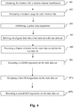
- Figure 4 is a flow chart for explaining a process for identifying among the set of wireless links SWL1-SWL3 which one is causing interference on another set of wireless links SWL1-SWL3according to an embodiment of the invention.
- a (set of) wireless link WL causing interference is called a bad neighbor.
- each end-point 1-3 acting as an access point measures for its set of wireless links SWL1-SWL3 a value of the relative channel interference. Such a measurement is executed for example each 10 seconds. Those measurements are reported to the communication device 11.
- a set of wireless link may comprise only one wireless link.
- each end-point 1-3 acting as an access point measures for its set of wireless links SWL1-SWL3 a value of the medium usage for the considered frequency channels. Such a measurement is executed for example each 2 seconds. Those measurements are reported to the communication device 11.
- Step 401 and step 402 can be executed at the same time.
- only end-point 1-3 acting as an access point whose sets of wireless links are potentially suffering interference need to report values of the relative channel interference and only potentially bad neighbors need to report values of the wireless medium usage in order to reduce the amount of data to be processed to identify the set of wireless links causing the interference.
- Data related to the measurements gathered by the communication device 11 during steps 401 and 402 are to be compared for identifying bad neighbors among the sets of wireless links SWL1-SWL3.
- a global alignment of data is performed by the communication device 11 during a step 403. This is done, for example, by defining consecutive 10 second time intervals that are the same for every wireless link and allocating values of the measurements of the relative channel interference and the values of measurements of the wireless medium usage.to each of these time intervals in a weighted manner.
- Table 1 to Table 3 The result of this data alignment is shown in Table 1 to Table 3.
- Table represents the measurements of the relative channel interference for a given wireless link as well as their associated weights.
- All the measurements gathered by the communication device 11 are assigned to one or two time intervals in a linearly weighted manner, based on how much of the considered measurement belongs to the time interval. If a frequency channel change occurs during a measurement, the measurement is dropped.
- a minimum value for the sum of the weights associated to measurements allocated to a given time interval prevents slivers of data to represent a whole time interval. If the value of the sum of the weights associated to measurements allocated to a given time interval is below the minimum value, then the time interval is not considered for the identification of the set of wireless links SWL1-SWL3 causing the interference.
- the minimum value is set to 0.5.
- the communication device 11 determines a weighted average of the measurements for each time interval as shown in Table 2.
- Table 2 the time interval starting at 2017-05-31 12:00:40 is dropped since the total weight associated with the measurements in this time interval is less than 0.5.
- the communication device brings together the metrics of the relative channel interference and the metrics of the medium usage for the same frequency channel in each time interval.
- An example of a SQL query executed by the communication device 11 to achieve this goal is shown below.
- an analytical table is defined as follows:
- Table 3 below is an example of the table generated by the communication device 11 in step 403 according to an embodiment of the invention.
- the table 3 is split into a plurality of tables, e.g. one table per suffering set of wireless links, because the identification of the set of wireless links causing interference is executed over one potentially suffering set of wireless links SWL1-SWL3 at a time.
- the communication device splits the dataset, i.e. the data stored in table 3 at random in a train set and test set.
- the used fractions are 90% of the data for the train set and 10%of the data for the test set, but other common values are also expected to result in decent performance. Splitting the data between a train set and a test set is motivated by the following reasons:
- the communication device 11 After the splitting of the data in a train set and test set, the communication device 11 performs some basic operations on the data sets during a step 405 called feature selection. If the train set and the test sets together hold less than X rows, the analysis is stopped. This filtering is optional and can help reduce the risk of bogus results as well as speed up the wider analysis by not spending time on sets that are too small to be likely to turn up results. Experimentally, 1000 rows is found to be an acceptable lower limit to the numbers of rows.
- any wireless medium usage columns in the train set that never contains a value greater than or equal to a given value is dropped from both the train set and the test set. This is again a trade-off between speeding up the process on the one hand and maintain the accuracy on the other.
- the given value is left to 0, since most gets filtered out in the feature selection anyway.
- step 405 if the train set does not have more rows than medium usage columns after the above operations, the analysis is stopped. This to accommodate for some machine learning approaches which cannot cope with this situation.
- step 405 Even after performing step 405 to reduce the number of sets of wireless links SWL1-SWL3 to consider in order to identify which wireless links are causing interference, may still remain a high dimensional problem since there may be hundreds of set of wireless links SWL1-SWL3 in very dense neighborhoods.
- the communication device 11 trains, in a step 406 a LASSO regression on the train set as follows:
- the LASSO regression is trained through a least angle regression with the Bayes Information Criterion as metric to evaluate lambdas.
- the other inputs are dropped from both the train set and the test set.
- a step 407 the communication device 11 performs a separate OLS (ordinary least squares) regression on the data obtained after step 406.
- OLS ordinary least squares
- the communication device 11 executes a performance analysis: how important is every input for explaining the interference.
- Step 407 may be split into two sub-steps 407a and 407b.
- the communication device 11 executes a first OLS regression on the train set, taking into account all the inputs, i.e. the values of the wireless medium usage, that got through the feature selection during step 405, plus an intercept.
- the performance of the model is measured by calculating a first R-Squared metric R 2 when predicting the performance on the test set. It can be seen as determining which proportion of the variance in the values of the relative channel interference can be explained by the model, making use of the values of the medium usages.
- the communication device 11 executes a second OLS regression the train set, omitting that input.
- a second R 2 metric is calculated every time on the test set.
- a 'bad neighbor' score is determined by the communication device 11 for each set of wireless links SWL1-SWL3. This 'bad neighbor' score is the first R 2 minus the second R 2 . This in effect gives an estimate on how much of the variance of the value of the interference is at least due to that specific set of wireless links.
Landscapes
- Engineering & Computer Science (AREA)
- Computer Networks & Wireless Communication (AREA)
- Signal Processing (AREA)
- Mobile Radio Communication Systems (AREA)
Abstract
Description
- The present invention relates to wireless local area networks (WLANs) and more particularly to the identification of a t least one wireless link within a WLAN causing interference on other wireless links used by WLANs for exchanging data.
- Typically, a WLAN consists of set of stations and one or more access points that establish wireless links between each other.
- Gateways are widely used to connect devices located in a home to the Internet or any other wide area network (WAN). Gateways use for example Digital Subscriber Line (DSL) technology that enables a high data rate transmission over copper lines or optical lines. Gateways, but also other devices such as routers, switches, telephones and set-top boxes, are understood in this context as Customer Premises Equipment (CPE) devices.
- Gateways including wireless technology have a key role in today's home and professional environments. A mechanism for connecting wireless devices to a Local Area Network (LAN) is called Wi-Fi, which is a brand name of the Wi-Fi Alliance for devices using the IEEE 802.11 family of standards for wireless data transmission. The IEEE 802.11 standards define two types of wireless nodes, a general wireless device that can connect to other devices called a station and a special type of station that is in control of the network, namely an access point. A Wi-Fi network, often called a WLAN (Wireless Local Area Network), consists of one or more access points embedded in a gateway connected to one or several stations. Of course, gateways may use other mechanisms for connecting wireless devices to a Local Area Network (LAN).
- Due to its flexible and "invisible" nature, a lot of local area network devices are utilizing Wi-Fi rather than the classical wired Ethernet approach. This widespread usage of wireless local area network has exposed however a serious downside of using a shared medium technology : interference. Interference, both Wi-Fi and non-Wi-Fi related, leads to a degraded user experience due to the nature of IEEE 802.11.
- An important aspect when configuring a wireless local area network, is the allocation of a frequency channel to a given access point. Auto Channel Selection (ACS) algorithms allow the access points to scan the various frequency channels available and select a frequency channel based on several parameters such as background noise, communication medium business, the number of neighboring access points based on beacon messages received from other access points as well as the Received Signal Strength Indication (RSSI) with which these beacon messages are received, etc.
- In environments such as buildings in which access points are densely deployed, those access points influence each other, in particular, by causing interference to one another or by sharing the wireless medium. In order to provide a frequency channel allocation scheme in such densely populated environments information gathered by the access points are collected in a centralized manner so as to coordinate the frequency channel allocation between the different access points. That information is for example, for a given access point, a list of neighboring access points, the frequency channel allocated to those neighboring access points as well as the respective RSSI, etc.
- In case an access point has less neighboring access points than the number of available frequency channels, a straightforward solution consists in allocating non-overlapping frequency channels to each of the neighboring access points. Such a solution cannot be implemented in densely populated environments where an access point has more neighboring access points than the number of available frequency channels.
- In such a situation, relying on a list of neighboring access points, background noise, communication medium business, the beacon messages received from neighboring access points as well as the Received Signal Strength Indication (RSSI) with which these beacon messages are received, etc. may lead to a frequency channel allocation scheme that may not significantly reduce the interference between access points because the correlation between interference and the above-mentioned parameters is not well known and/or deterministic.
- The present invention has been devised with the foregoing in mind.
- According to a first aspect of the invention there is provided a computer implemented method for identifying, among a set of wireless links established between at least two wireless end-points, at least a first wireless link causing interferences on at least a second wireless link belonging to said set of wireless links, said method comprising:
- Generating at least a set of data enabling the identification of the first wireless link by allocating measurements of an amount of performance loss of a wireless link due to interferences, and measurements of a use of a wireless medium by either said first wireless link or said second wireless link, to a given time interval of a set of time intervals in a weighted manner based on a time overlap between a time interval during which said measurements are performed and at least a given time interval of said set of time intervals,
- Such a method according to an embodiment of the invention enables the identification of at least one wireless link causing interferences on other wireless links. The wireless link causing the interferences is referred to as a bad neighbor. A wireless link is established between two wireless end-point devices. A wireless link may use a plurality of frequency channels for transmitting data to and from the stations, but only one at the time.
- The interference may be performance loss due to the sharing of the wireless medium between a plurality of wireless links, Near End Inference, Far End Interference or a combination of those.
- The method according to an embodiment of the invention relies on the use of a first metric representing the hinderance experienced by a wireless link and of a second metric representing the usage of the communication medium by wireless links located in the vicinity of each other.
- The first metric is for example a value representing an amount of performance lost due the interference relatively to a maximum performance of the wireless link under consideration.
- The second metric is the wireless medium usage because the more time the medium is used simultaneously by the wireless link suffering the interference and the bad neighbor, the more interference are generated.
- In an embodiment of the invention, only the wireless links potentially suffering interference is reporting the first metric and only wireless links potentially behaving as bad neighbors report the second metric.
- In another embodiment of the invention, all the wireless links of a set of wireless links report the first and the second metric.
- Each wireless link reports the first and the second metrics at different moment in time. In order to make all the measurements reported by the different wireless links exploitable, these measurements are allocated to different, across-end-point-consistent i.e. the same time intervals are created for all end-points so that the time intervals created for every end-point start and end at the same moments in time, time intervals depending on the schedule of the measurement relatively to said time intervals. If a measurement can be allocated to two different time intervals, the measurement is allocated to the two time intervals in a weighted manner based on a time overlap between the schedule of the measurements and at the time intervals.
- According to an embodiment of the invention, a sum of the weights associated to measurements allocated to a given time interval is greater than or equal to a threshold.
- A minimum value for the sum of the weights associated to measurements allocated to a given time interval prevents slivers of data to represent a whole time interval. If the value of the sum of the weights associated to measurements allocated to a given time interval is below the minimum value, then the time interval is not considered for the identification of the wireless link causing the interference.
- According to an embodiment of the invention, identifying the at least first wireless link based on the set of data comprises:
- Splitting the data set into a training set and a test set,
- Training a first performance analysis by running a least square regression on the metrics of a wireless medium usage of the train set, the performance being measured by calculating a R-Squared metrics on the train set while predicting a performance for the test set,
- For at least one metric of a wireless medium usage performing a second performance analysis by training a least square regression on the metrics of a wireless medium usage of the train set minus the considered metric of a wireless medium usage, the performance being measured by calculating a R-Squared metrics on the test set minus the considered metric of a wireless medium usage while predicting a performance for the test set,
- Determining a score for at least one wireless link belonging to said set of wireless links by substracting the value of the R-Squared metrics obtained on the test set minus the considered metric of a wireless medium usage from the value of the R-Squared metrics obtained on the test set, the higher the score of a wireless link the more hindering the interference caused by said wireless link on the other wireless link.
- According to an embodiment of the invention, prior to perform the first performance analysis, a LASSO regression is performed on said train set.
- This implementation has two benefits. Firstly, it allows non-penalized coefficients while delivering a sparse solution. Secondly, using least square regression it is possible to control which input is left out, allowing to check how indispensable the input truly is.
- In order to identify a wireless link as causing interference on a given frequency channel two criteria are confirmed.
- The identification of at least a wireless link causing interference on at least another wireless link may be a high-dimensional problem since in dense neighborhoods, there might be hundreds of wireless links used for exchanging data. In order to deal with this high-dimension issue, a LASSO (Least Absolute Shrinkage and Selection Operator)) regression is performed on the train set.
- LASSO is a regression analysis method that performs both variable selection and regularization in order to enhance the prediction accuracy and interpretability of the statistical model it produces.
- LASSO regression was introduced in order to improve the prediction accuracy and interpretability of regression models by altering the model fitting process to select only a subset of the provided covariates for use in the final model rather than using all of them.
- LASSO regression consists in forcing the sum of the absolute value of the regression coefficients to be less than a fixed value, which forces certain coefficients to be set to zero, effectively choosing a simpler model that does not include those coefficients.
- LASSO regression is performed on the train set as followed: the value to predict is the interference, the input used for the prediction are the metrics of the wireless medium usage belonging to the train set.
- Another object of the invention is a device capable of identifying, among a set of wireless links, at least a first wireless link causing interferences on at least a second wireless link belonging to said set of wireless links, said device comprising at least a hardware processor configured to:
- generate at least a set of data enabling the identification of the first wireless link by allocating measurements of an amount of performance loss of a wireless link due to interferences, and measurements of a use of wireless medium by either said first wireless link or said second wireless link, to a given time interval of a set of time intervals in a weighted manner based on a time overlap between a time interval during which said measurements are performed and at least a given time interval of said set of time intervals,
- identify, based on said at least set of data, at least said first wireless link within said set of wireless links.
- According to an embodiment of the invention, said hardware processor is further configured to:
- Split the data set into a training set and a test set,
- Perform a first performance analysis by training a least square regression on the metrics of a wireless medium usage of the train set, the performance being measured by calculating a R-Squared metrics on the test set while predicting a performance for the test set,
- For at least one metric of a wireless medium usage, perform a second performance analysis by training a least square regression on the metrics of a wireless medium usage of the train set minus the considered metric of a wireless medium usage, the performance being measured by calculating a R-Squared metrics on the test set minus the considered metric of a wireless medium usage while predicting a performance for the test set,
- Determine a score for at least one wireless link belong to said set of wireless links by substracting the value of the R-Squared metrics obtained on the test set minus the considered metric of a wireless medium usage from the value of the R-Squared metrics obtained on the test set, the higher the score of a wireless link the more hindering the interference caused by said wireless link on the frequency channel.
- According to an embodiment of the invention, prior to perform the first performance analysis, the hardware processor is configured to perform a LASSO regression on said train set.
- Some processes implemented by elements of the invention may be computer implemented. Accordingly, such elements may take the form of an entirely hardware embodiment, an entirely software embodiment (including firmware, resident software, micro-code, etc.) or an embodiment combining software and hardware aspects that may all generally be referred to herein as a "circuit", "module" or "system'. Furthermore, such elements may take the form of a computer program product embodied in any tangible medium of expression having computer usable program code embodied in the medium.
- Since elements of the present invention can be implemented in software, the present invention can be embodied as computer readable code for provision to a programmable apparatus on any suitable carrier medium. A tangible carrier medium may comprise a storage medium such as a floppy disk, a CD-ROM, a hard disk drive, a magnetic tape device or a solid-state memory device and the like. A transient carrier medium may include a signal such as an electrical signal, an electronic signal, an optical signal, an acoustic signal, a magnetic signal or an electromagnetic signal, e.g. a microwave or RF signal.
- Embodiments of the invention will now be described, by way of example only, and with reference to the following drawings in which:
-
Figure 1 represents a system S comprising a plurality of wireless end-points located for example in a same building B, -
Figure 2 represents a more detailed view of one of the end-points according to an embodiment of the invention, -
Figure 3 is a schematic block diagram illustrating an example of a communication device according to an embodiment of the invention, -
Figure 4 is a flow chart for explaining a process for identifying among the wireless links which one is causing interference on another wireless link according to an embodiment of the invention. - The elements shown in
figure 1 may be implemented in various forms of hardware, software or combinations thereof. Preferably, these elements are implemented in a combination of hardware and software on one or more appropriately programmed general-purpose devices, which may include a processor, memory and input/output interfaces. Herein, the phrase "coupled" is defined to mean directly connected to or indirectly connected with through one or more intermediate components. Such intermediate components may include both hardware and software based components. - The present description illustrates the principles of the present disclosure. It will thus be appreciated that those skilled in the art will be able to devise various arrangements that, although not explicitly described or shown herein, embody the principles of the disclosure and are included within its spirit and scope.
- A CPE device includes, but is not limited to, for example a controller, e.g. a microprocessor, a memory, in which an operating system is stored for the operation of the CPE device, a wireless node for a wireless communication, and a circuit for a broadband connection, e.g. an xDSL connection. The wireless node includes, but is not limited to, a software driver, a physical layer with data buffers, and an antenna. A CPE device of this kind is for example an access gateway.
- The wireless node is controlled by the software driver which executes a number of background tasks during operation of the wireless node, e.g. dynamic rate adaptation, packet aggregation, channel quality monitoring, and the like. On top of signal manipulations, the wireless driver also embeds an IEEE 802.11 protocol stack with the associated IEEE defined management and control messaging. The wireless driver will hence inject a number of management and control packets in the data stream, making it difficult to analyze a link by transparently looking at the data frame exchange only.
-
Figure 1 represents a system S comprising a plurality of wireless end-points 1-10 located for example in a same building B. Wireless links WL are established between these end-points 1-10. For example, wireless links are established between the end-points points points 3, 4 and 7. In this example, the end-points points - Data such as data rate, physical layer data rate, an amount of spatial streams used, channel bandwidth, medium availability and Received Signal Strength Indicator (RSSI) from associated stations are collected for each wireless links and are transmitted to at least one
remote communication device 11 belonging to the same Internet Service Provider controlling the wireless access points 1-3, or may be managed by a third party, and execute the method according to an embodiment of the invention. -
Figure 2 represents a more detailed view of one of the end-points 1-10 according to an embodiment of the invention. - An end-point 1-10 may comprise at least one
hardware processor 101, astorage unit 102, an input device 103, adisplay device 104, aninterface unit 105, anetwork interface 107, at least onewireless interface 108 and a controllingmodule 109 which are connected by abus 106. Of course, constituent elements of the end-point 1-10 may be connected by a connection other than a bus connection. - The
processor 101 controls operations of the end-point 1-10. Thestorage unit 102 stores at least one program capable of monitoring and managing wireless communications to and from the end-point 1-10, to be executed by theprocessor 101, and various data, such as parameters used by computations performed by theprocessor 101, intermediate data of computations performed by theprocessor 101, and so on. Theprocessor 101 may be formed by any known and suitable hardware, or software, or a combination of hardware and software. For example, theprocessor 101 may be formed by dedicated hardware such as a processing circuit, or by a programmable processing unit such as a CPU (Central Processing Unit) that executes a program stored in a memory thereof. - The
storage unit 102 may be formed by any suitable storage or means capable of storing the program, data, or the like in a computer-readable manner. Examples of thestorage unit 102 include non-transitory computer-readable storage media such as semiconductor memory devices, and magnetic, optical, or magneto-optical recording media loaded into a read and write unit. The program causes theprocessor 101 to perform a process according to an embodiment of the present disclosure as described hereinafter with reference tofigure 4 . - The input device 103 may be formed by a keyboard, a pointing device such as a mouse, or the like for use by the user to input commands, for example to make user's selections of parameters used for selecting the transmission interface to be used. The
display device 104 may be formed by a display device to display, for example, a Graphical User Interface (GUI). The input device 103 and thedisplay device 104 may be formed integrally by a touchscreen panel, for example. - The
interface unit 105 provides an interface between the end-point 1-10 and an external apparatus. Theinterface unit 105 may be communicable with the external apparatus via cable or wireless communication. Such an external apparatus is for example a Set Top Box or a smartphone. - A
network interface 107 provides a connection between the end-point 1-10 and thecommunication device 11 via a backbone network (not shown in the figures), such as the Internet. Thenetwork interface 107 may provide, depending on its nature, a wired or a wireless connection to the backbone network. - A
wireless interface 108 provides a wireless connection, for example a Wi-Fi connection, between the end-point 1-10 and at least one station, e.g. a mobile phone (not shown on the figures), associated with said end-point 1-10. - A
monitoring module 109 analyzes and evaluates the wireless link WL established between the end-point monitoring module 109 may include data rate, physical layer data rate, amount of spatial streams used, channel bandwidth, medium availability and Received Signal Strength Indicator (RSSI) from associated stations as well as from neighboring wireless links WL, values representing an amount of performance lost due the interference relatively to a maximum performance of the wireless link under consideration called relative channel interference, or values that can be used to calculate the amount of performance loss, etc. -
Figure 3 is a schematic block diagram illustrating an example of acommunication device 11 according to an embodiment of the invention. - The
communication device 11 comprises at least onehardware processor 1101, astorage unit 1102, aninput device 1103, adisplay device 1104, aninterface unit 1105 and anetwork interface 1107 and acontrolling module 1108 which are connected by abus 1106. Of course, constituent elements of thecommunication device 11 may be connected by a connection other than a bus connection. - The
processor 1101 controls operations of thecommunication device 11. Thestorage unit 1102 stores at least one program capable of being executed by theprocessor 1101, and various data, such as parameters used by computations performed by theprocessor 1101, intermediate data of computations performed by theprocessor 1101, and so on. Theprocessor 1101 may be formed by any known and suitable hardware, or software, or a combination of hardware and software. For example, theprocessor 1101 may be formed by dedicated hardware such as a processing circuit, or by a programmable processing unit such as a CPU (Central Processing Unit) that executes a program stored in a memory thereof. - The
storage unit 1102 may be formed by any suitable storage or means capable of storing the program, data, or the like in a computer-readable manner. Examples of thestorage unit 1102 include non-transitory computer-readable storage media such as semiconductor memory devices, and magnetic, optical, or magneto-optical recording media loaded into a read and write unit. The program causes theprocessor 1101 to perform a process according to an embodiment of the present disclosure as described hereinafter with reference tofigure 4 . - The
input device 1103 may be formed by a keyboard, a pointing device such as a mouse, or the like for use by the user to input commands, to make user's selections of parameters used for selecting the transmission interface to be used. Theoutput device 1104 may be formed by a display device to display, for example, a Graphical User Interface (GUI). Theinput device 1103 and theoutput device 1104 may be formed integrally by a touchscreen panel, for example. - The
interface unit 1105 provides an interface between thecommunication device 11 and an external apparatus. Theinterface unit 1105 may be communicable with the external apparatus via cable or wireless communication. - The
network interface 1107 provides a connection between thecommunication device 11 and the end-points 1-10 through a backbone network (not shown in the figures), such as the Internet. Thenetwork interface 1107 may provide, depending on its nature, a wired or a wireless connection to the backbone network. - The controlling
module 109 analyzes and evaluates the wireless links WL established between the end-points 1-3 and their respective end-points 4-10 as well as the interference that may be caused said wireless links WL on the shared wireless medium. The information gathered by the controllingmodule 109 may include achievable data rate, physical layer data rate, multiple spatial streams, channel bandwidth, medium availability and Received Signal Strength Indicator (RSSI), values representing an amount of performance lost due the interference relatively to a maximum performance of the wireless link under consideration, the medium usage, or values that can be used to calculate the amount of performance loss, etc. -
Figure 4 is a flow chart for explaining a process for identifying among the set of wireless links SWL1-SWL3 which one is causing interference on another set of wireless links SWL1-SWL3according to an embodiment of the invention. In the following description, a (set of) wireless link WL causing interference is called a bad neighbor. - In a
step 401, each end-point 1-3 acting as an access point measures for its set of wireless links SWL1-SWL3 a value of the relative channel interference. Such a measurement is executed for example each 10 seconds. Those measurements are reported to thecommunication device 11. A set of wireless link may comprise only one wireless link. - In a
step 402, each end-point 1-3 acting as an access point measures for its set of wireless links SWL1-SWL3 a value of the medium usage for the considered frequency channels. Such a measurement is executed for example each 2 seconds. Those measurements are reported to thecommunication device 11. - Step 401 and step 402 can be executed at the same time.
- In an embodiment of the invention, only end-point 1-3 acting as an access point whose sets of wireless links are potentially suffering interference need to report values of the relative channel interference and only potentially bad neighbors need to report values of the wireless medium usage in order to reduce the amount of data to be processed to identify the set of wireless links causing the interference.
- Data related to the measurements gathered by the
communication device 11 duringsteps communication device 11 during astep 403. This is done, for example, by defining consecutive 10 second time intervals that are the same for every wireless link and allocating values of the measurements of the relative channel interference and the values of measurements of the wireless medium usage.to each of these time intervals in a weighted manner. The result of this data alignment is shown in Table 1 to Table 3. - Table represents the measurements of the relative channel interference for a given wireless link as well as their associated weights.

- All the measurements gathered by the
communication device 11 are assigned to one or two time intervals in a linearly weighted manner, based on how much of the considered measurement belongs to the time interval. If a frequency channel change occurs during a measurement, the measurement is dropped. - A minimum value for the sum of the weights associated to measurements allocated to a given time interval prevents slivers of data to represent a whole time interval. If the value of the sum of the weights associated to measurements allocated to a given time interval is below the minimum value, then the time interval is not considered for the identification of the set of wireless links SWL1-SWL3 causing the interference. In an embodiment of the invention, the minimum value is set to 0.5.
- Then, the
communication device 11 determines a weighted average of the measurements for each time interval as shown in Table 2. In Table 2, the time interval starting at 2017-05-31 12:00:40 is dropped since the total weight associated with the measurements in this time interval is less than 0.5.
         SELECT CASE WHEN l.interval IS NULL THEN r.interval else l.interval END AS interval,
            CASE WHEN l.radio_id IS NULL THEN r.radio_id else l.radio_id END AS radio_id,
            CASE WHEN l.channel IS NULL THEN r.channel else l.channel END AS channel,
            l.channel_interference,
            r.medium_usage
         FROM aligned_interference_data AS I
         OUTER JOIN aligned_usage_data AS r
         ON (l.interval = r.interval AND l.radio_id = r.radio_id and l.channel = r.channel)
- One row per time interval per frequency channel if the wireless medium usage on that combination is not 0 for the set of wireless links experiencing interference.
- One column containing a value of said interference
- One column per set of wireless links (AP in the table) considered a potential bad neighbor, containing the value of the wireless medium usage for the same time interval and same frequency channel.


- the implementation of the invention does not use any hyperparameter optimization,
- doing so is computationally cheaper than other evaluation methods such as cross-validation.
- The analysis is halted and considered unfeasible on the current data.
- The train set and the test set still have the same number of rows, but may have shed some columns. The columns present in the train and the test set are the same ones.
- The value to predict is the relative channel interference,
- The inputs to use for a prediction are the values of medium usages of the frequency channels which are in the train set,
- a constant value may be used as additional input to use for a prediction,
- non-negative coefficients are forced.
- it allows for non-penalized coefficients (i.e., no shrinking) whilst still delivering a sparse solution,
- the sets of wireless links SWL1-SWL3 potentially causing interference are evaluated by training modified models. By using OLS models, it possible to control which input is left out.
- Strong relation: does a change in the set of wireless links' wireless medium usage impacts on the set of wireless links experiencing interference?
- Important relation: does the relation as mentioned as the first criterium explains a non-trivial amount of the experienced interference.
Claims (10)
- A computer implemented method for identifying, among a set of wireless links established between at least two wireless end-points, at least a first wireless link causing interferences on at least a second wireless link belonging to said set of wireless links, said method comprising:• Generating at least a set of data enabling the identification of the first wireless link by allocating measurements of an amount of performance loss of a wireless link due to interferences, and measurements of a use of a wireless medium by either said first wireless link or said second wireless link, to a given time interval of a set of time intervals in a weighted manner based on a time overlap between a time interval during which said measurements are performed and at least a given time interval of said set of time intervals,• identifying, based on said at least set of data, at least said first wireless link within said set of wireless links.
- The method according to claim 1 wherein a sum of the weights associated to measurements allocated to a given time interval is greater than or equal to a threshold.
- The method according to claim 1 wherein identifying the at least first wireless link based on the set of data comprises:• Splitting the data set into a training set and a test set,• Training a first performance analysis by running a least square regression on the metrics of a wireless medium usage of the train set, the performance being measured by calculating a R-Squared metrics on the train set while predicting a performance for the test set,• For at least one metric of a wireless medium usage performing a second performance analysis by training a least square regression on the metrics of a wireless medium usage of the train set minus the considered metric of a wireless medium usage, the performance being measured by calculating a R-Squared metrics on the test set minus the considered metric of a wireless medium usage while predicting a performance for the test set,• Determining a score for at least one wireless link belong to said set of wireless link wireless links by substracting the value of the R-Squared metrics obtained on the test set minus the considered metric of a wireless medium usage from the value of the R-Squared metrics obtained on the test set, the higher the score of a wireless link the more hindering the interference caused by said wireless link wireless link on another wireless link.
- The method according to claim 3 wherein, prior to perform the first performance analysis, a LASSO regression is performed on said train set.
- A device capable of identifying, among a set of wireless links, at least a first wireless link causing interferences on at least a second wireless link belonging to said set of wireless links, said device comprising at least a hardware processor configured to:• generate at least a set of data enabling the identification of the first wireless link by allocating measurements wireless link of an amount of performance loss of a wireless link due to interferences, and measurements of a use of wireless medium by either said first wireless link or said second wireless link, to a given time interval of a set of time intervals in a weighted manner based on a time overlap between a time interval during which said measurements are performed and at least a given time interval of said set of time intervals,• identify, based on said at least set of data, at least said first wireless link within said set of wireless links.
- The device according to claim 5 wherein said hardware processor is further configured to:• Split the data set into a training set and a test set,• Perform a first performance analysis by training a least square regression on the metrics of a wireless medium usage of the train set, the performance being measured by calculating a R-Squared metrics on the test set while predicting a performance for the test set,• For at least one metric of a wireless medium usage, perform a second performance analysis by training a least square regression on the metrics of a wireless medium usage of the train set minus the considered metric of a wireless medium usage, the performance being measured by calculating a R-Squared metrics on the test set minus the considered metric of a wireless medium usage while predicting a performance for the test set,• Determine a score for at least one wireless link belong to said set of wireless links by substracting the value of the R-Squared metrics obtained on the test set minus the considered metric of a wireless medium usage from the value of the R-Squared metrics obtained on the test set, the higher the score of a wireless link the more hindering the interference caused by said wireless link on another wireless link.
- The device according to claim 6 wherein, prior to perform the first performance analysis, the hardware processor is configured to perform a LASSO regression on said train set.
- A computer program characterized in that it comprises program code instructions for the implementation of the method according to claim 1 when the program is executed by a processor.
- A processor readable medium having stored therein instructions for causing a processor to perform the method according to claim 1.
- Non-transitory storage medium carrying instructions of program code for executing the method according to claim 1, when said program is executed on a computing device.
Priority Applications (2)
| Application Number | Priority Date | Filing Date | Title |
|---|---|---|---|
| EP22163165.8A EP4037363A1 (en) | 2017-12-22 | 2017-12-22 | A method for identifying at least a wireless link causing interferences on other wireless links |
| EP17306925.3A EP3503610B1 (en) | 2017-12-22 | 2017-12-22 | A method and device for identifying at least a wireless link causing interferences on other wireless links |
Applications Claiming Priority (1)
| Application Number | Priority Date | Filing Date | Title |
|---|---|---|---|
| EP17306925.3A EP3503610B1 (en) | 2017-12-22 | 2017-12-22 | A method and device for identifying at least a wireless link causing interferences on other wireless links |
Related Child Applications (1)
| Application Number | Title | Priority Date | Filing Date |
|---|---|---|---|
| EP22163165.8A Division EP4037363A1 (en) | 2017-12-22 | 2017-12-22 | A method for identifying at least a wireless link causing interferences on other wireless links |
Publications (2)
| Publication Number | Publication Date |
|---|---|
| EP3503610A1 true EP3503610A1 (en) | 2019-06-26 |
| EP3503610B1 EP3503610B1 (en) | 2022-03-23 |
Family
ID=60957109
Family Applications (2)
| Application Number | Title | Priority Date | Filing Date |
|---|---|---|---|
| EP22163165.8A Pending EP4037363A1 (en) | 2017-12-22 | 2017-12-22 | A method for identifying at least a wireless link causing interferences on other wireless links |
| EP17306925.3A Active EP3503610B1 (en) | 2017-12-22 | 2017-12-22 | A method and device for identifying at least a wireless link causing interferences on other wireless links |
Family Applications Before (1)
| Application Number | Title | Priority Date | Filing Date |
|---|---|---|---|
| EP22163165.8A Pending EP4037363A1 (en) | 2017-12-22 | 2017-12-22 | A method for identifying at least a wireless link causing interferences on other wireless links |
Country Status (1)
| Country | Link |
|---|---|
| EP (2) | EP4037363A1 (en) |
Citations (2)
| Publication number | Priority date | Publication date | Assignee | Title |
|---|---|---|---|---|
| US20050153667A1 (en) * | 2004-01-08 | 2005-07-14 | Interdigital Technology Corporation | Escape mechanism for a wireless local area network |
| WO2016174728A1 (en) * | 2015-04-28 | 2016-11-03 | 富士通株式会社 | Channel allocation device, wireless communication system, and channel allocation method |
Family Cites Families (1)
| Publication number | Priority date | Publication date | Assignee | Title |
|---|---|---|---|---|
| CN105517019B (en) * | 2015-12-17 | 2019-03-08 | 南京华苏科技有限公司 | Using the method for integrated regression system detection LTE network performance |
-
2017
- 2017-12-22 EP EP22163165.8A patent/EP4037363A1/en active Pending
- 2017-12-22 EP EP17306925.3A patent/EP3503610B1/en active Active
Patent Citations (3)
| Publication number | Priority date | Publication date | Assignee | Title |
|---|---|---|---|---|
| US20050153667A1 (en) * | 2004-01-08 | 2005-07-14 | Interdigital Technology Corporation | Escape mechanism for a wireless local area network |
| WO2016174728A1 (en) * | 2015-04-28 | 2016-11-03 | 富士通株式会社 | Channel allocation device, wireless communication system, and channel allocation method |
| US20180049035A1 (en) * | 2015-04-28 | 2018-02-15 | Fujitsu Limited | Channel assignment apparatus, wireless communication system, and channel assignment method |
Non-Patent Citations (1)
| Title |
|---|
| AMIRI BAHADOR ET AL: "A New Approach for WLAN Channel Selection Based on Outage Capacity", MILCOM 2013 - 2013 IEEE MILITARY COMMUNICATIONS CONFERENCE, IEEE, 18 November 2013 (2013-11-18), pages 1657 - 1662, XP032563365, DOI: 10.1109/MILCOM.2013.281 * |
Also Published As
| Publication number | Publication date |
|---|---|
| EP3503610B1 (en) | 2022-03-23 |
| EP4037363A1 (en) | 2022-08-03 |
Similar Documents
| Publication | Publication Date | Title |
|---|---|---|
| Zhang et al. | Multi-agent deep reinforcement learning-based cooperative spectrum sensing with upper confidence bound exploration | |
| US20250062974A1 (en) | METHOD FOR PREDICTING A LEVEL OF QoE OF AN APPLICATION INTENDED TO BE RUN ON A WIRELESS USER EQUIPMENT | |
| EP4038837B1 (en) | Quality of experience measurements for control of wi-fi networks | |
| CN109089318B (en) | Method for allocating frequency channels to multiple adjacent access points | |
| Jeunen et al. | A machine learning approach for IEEE 802.11 channel allocation | |
| Morshedi et al. | A survey on prediction of PQoS using machine learning on Wi-Fi networks | |
| EP3503610B1 (en) | A method and device for identifying at least a wireless link causing interferences on other wireless links | |
| US20250330395A1 (en) | Smart service analyzer | |
| Molina et al. | Identifying channel saturation in Wi-Fi networks via passive monitoring of IEEE 802.11 beacon jitter | |
| EP4496380A1 (en) | Communication apparatus and method | |
| JP2020170932A (en) | Wireless performance evaluation method and wireless performance evaluation system | |
| CN112752291B (en) | Method and device for evaluating uplink rate | |
| US12317088B2 (en) | Selecting radio resource management schemes based on environment assessments | |
| US20250328850A1 (en) | Customer experience index estimator for a smart service analyzer | |
| US12556463B2 (en) | Normalizing a trend deviation-based quantitative key performance indictor (KPI) | |
| Allahdadi et al. | 802.11 Wireless Access Point Usage Simulation and Anomaly Detection | |
| US20250330398A1 (en) | Key performance indicator (kpi) normalization for a smart service analyzer | |
| Onalan et al. | Passive side-channel interference estimation for wifi networks | |
| Jiménez-Padilla et al. | Non-intrusive QoE prediction in WLAN | |
| Karami et al. | Resource Optimization and Hyperparameter Tuning in Decentralized Federated Learning via MPC |
Legal Events
| Date | Code | Title | Description |
|---|---|---|---|
| PUAI | Public reference made under article 153(3) epc to a published international application that has entered the european phase |
Free format text: ORIGINAL CODE: 0009012 |
|
| STAA | Information on the status of an ep patent application or granted ep patent |
Free format text: STATUS: THE APPLICATION HAS BEEN PUBLISHED |
|
| AK | Designated contracting states |
Kind code of ref document: A1 Designated state(s): AL AT BE BG CH CY CZ DE DK EE ES FI FR GB GR HR HU IE IS IT LI LT LU LV MC MK MT NL NO PL PT RO RS SE SI SK SM TR |
|
| AX | Request for extension of the european patent |
Extension state: BA ME |
|
| STAA | Information on the status of an ep patent application or granted ep patent |
Free format text: STATUS: REQUEST FOR EXAMINATION WAS MADE |
|
| 17P | Request for examination filed |
Effective date: 20191219 |
|
| RBV | Designated contracting states (corrected) |
Designated state(s): AL AT BE BG CH CY CZ DE DK EE ES FI FR GB GR HR HU IE IS IT LI LT LU LV MC MK MT NL NO PL PT RO RS SE SI SK SM TR |
|
| STAA | Information on the status of an ep patent application or granted ep patent |
Free format text: STATUS: EXAMINATION IS IN PROGRESS |
|
| 17Q | First examination report despatched |
Effective date: 20200513 |
|
| RIC1 | Information provided on ipc code assigned before grant |
Ipc: H04W 16/10 20090101AFI20210412BHEP Ipc: H04W 16/04 20090101ALN20210412BHEP Ipc: H04W 24/10 20090101ALN20210412BHEP Ipc: H04W 84/12 20090101ALN20210412BHEP |
|
| GRAP | Despatch of communication of intention to grant a patent |
Free format text: ORIGINAL CODE: EPIDOSNIGR1 |
|
| STAA | Information on the status of an ep patent application or granted ep patent |
Free format text: STATUS: GRANT OF PATENT IS INTENDED |
|
| RIC1 | Information provided on ipc code assigned before grant |
Ipc: H04W 16/10 20090101AFI20210423BHEP Ipc: H04W 16/04 20090101ALN20210423BHEP Ipc: H04W 24/10 20090101ALN20210423BHEP Ipc: H04W 84/12 20090101ALN20210423BHEP |
|
| INTG | Intention to grant announced |
Effective date: 20210531 |
|
| GRAS | Grant fee paid |
Free format text: ORIGINAL CODE: EPIDOSNIGR3 |
|
| GRAA | (expected) grant |
Free format text: ORIGINAL CODE: 0009210 |
|
| STAA | Information on the status of an ep patent application or granted ep patent |
Free format text: STATUS: THE PATENT HAS BEEN GRANTED |
|
| AK | Designated contracting states |
Kind code of ref document: B1 Designated state(s): AL AT BE BG CH CY CZ DE DK EE ES FI FR GB GR HR HU IE IS IT LI LT LU LV MC MK MT NL NO PL PT RO RS SE SI SK SM TR |
|
| RAP1 | Party data changed (applicant data changed or rights of an application transferred) |
Owner name: AIRTIES BELGIUM SPRL |
|
| REG | Reference to a national code |
Ref country code: GB Ref legal event code: FG4D |
|
| REG | Reference to a national code |
Ref country code: CH Ref legal event code: EP |
|
| REG | Reference to a national code |
Ref country code: DE Ref legal event code: R096 Ref document number: 602017054876 Country of ref document: DE |
|
| REG | Reference to a national code |
Ref country code: IE Ref legal event code: FG4D |
|
| REG | Reference to a national code |
Ref country code: AT Ref legal event code: REF Ref document number: 1478272 Country of ref document: AT Kind code of ref document: T Effective date: 20220415 |
|
| REG | Reference to a national code |
Ref country code: LT Ref legal event code: MG9D |
|
| REG | Reference to a national code |
Ref country code: NL Ref legal event code: MP Effective date: 20220323 |
|
| PG25 | Lapsed in a contracting state [announced via postgrant information from national office to epo] |
Ref country code: SE Free format text: LAPSE BECAUSE OF FAILURE TO SUBMIT A TRANSLATION OF THE DESCRIPTION OR TO PAY THE FEE WITHIN THE PRESCRIBED TIME-LIMIT Effective date: 20220323 Ref country code: RS Free format text: LAPSE BECAUSE OF FAILURE TO SUBMIT A TRANSLATION OF THE DESCRIPTION OR TO PAY THE FEE WITHIN THE PRESCRIBED TIME-LIMIT Effective date: 20220323 Ref country code: NO Free format text: LAPSE BECAUSE OF FAILURE TO SUBMIT A TRANSLATION OF THE DESCRIPTION OR TO PAY THE FEE WITHIN THE PRESCRIBED TIME-LIMIT Effective date: 20220623 Ref country code: LT Free format text: LAPSE BECAUSE OF FAILURE TO SUBMIT A TRANSLATION OF THE DESCRIPTION OR TO PAY THE FEE WITHIN THE PRESCRIBED TIME-LIMIT Effective date: 20220323 Ref country code: HR Free format text: LAPSE BECAUSE OF FAILURE TO SUBMIT A TRANSLATION OF THE DESCRIPTION OR TO PAY THE FEE WITHIN THE PRESCRIBED TIME-LIMIT Effective date: 20220323 Ref country code: BG Free format text: LAPSE BECAUSE OF FAILURE TO SUBMIT A TRANSLATION OF THE DESCRIPTION OR TO PAY THE FEE WITHIN THE PRESCRIBED TIME-LIMIT Effective date: 20220623 |
|
| REG | Reference to a national code |
Ref country code: AT Ref legal event code: MK05 Ref document number: 1478272 Country of ref document: AT Kind code of ref document: T Effective date: 20220323 |
|
| PG25 | Lapsed in a contracting state [announced via postgrant information from national office to epo] |
Ref country code: LV Free format text: LAPSE BECAUSE OF FAILURE TO SUBMIT A TRANSLATION OF THE DESCRIPTION OR TO PAY THE FEE WITHIN THE PRESCRIBED TIME-LIMIT Effective date: 20220323 Ref country code: GR Free format text: LAPSE BECAUSE OF FAILURE TO SUBMIT A TRANSLATION OF THE DESCRIPTION OR TO PAY THE FEE WITHIN THE PRESCRIBED TIME-LIMIT Effective date: 20220624 Ref country code: FI Free format text: LAPSE BECAUSE OF FAILURE TO SUBMIT A TRANSLATION OF THE DESCRIPTION OR TO PAY THE FEE WITHIN THE PRESCRIBED TIME-LIMIT Effective date: 20220323 |
|
| PG25 | Lapsed in a contracting state [announced via postgrant information from national office to epo] |
Ref country code: NL Free format text: LAPSE BECAUSE OF FAILURE TO SUBMIT A TRANSLATION OF THE DESCRIPTION OR TO PAY THE FEE WITHIN THE PRESCRIBED TIME-LIMIT Effective date: 20220323 |
|
| PG25 | Lapsed in a contracting state [announced via postgrant information from national office to epo] |
Ref country code: SM Free format text: LAPSE BECAUSE OF FAILURE TO SUBMIT A TRANSLATION OF THE DESCRIPTION OR TO PAY THE FEE WITHIN THE PRESCRIBED TIME-LIMIT Effective date: 20220323 Ref country code: SK Free format text: LAPSE BECAUSE OF FAILURE TO SUBMIT A TRANSLATION OF THE DESCRIPTION OR TO PAY THE FEE WITHIN THE PRESCRIBED TIME-LIMIT Effective date: 20220323 Ref country code: RO Free format text: LAPSE BECAUSE OF FAILURE TO SUBMIT A TRANSLATION OF THE DESCRIPTION OR TO PAY THE FEE WITHIN THE PRESCRIBED TIME-LIMIT Effective date: 20220323 Ref country code: PT Free format text: LAPSE BECAUSE OF FAILURE TO SUBMIT A TRANSLATION OF THE DESCRIPTION OR TO PAY THE FEE WITHIN THE PRESCRIBED TIME-LIMIT Effective date: 20220725 Ref country code: ES Free format text: LAPSE BECAUSE OF FAILURE TO SUBMIT A TRANSLATION OF THE DESCRIPTION OR TO PAY THE FEE WITHIN THE PRESCRIBED TIME-LIMIT Effective date: 20220323 Ref country code: EE Free format text: LAPSE BECAUSE OF FAILURE TO SUBMIT A TRANSLATION OF THE DESCRIPTION OR TO PAY THE FEE WITHIN THE PRESCRIBED TIME-LIMIT Effective date: 20220323 Ref country code: CZ Free format text: LAPSE BECAUSE OF FAILURE TO SUBMIT A TRANSLATION OF THE DESCRIPTION OR TO PAY THE FEE WITHIN THE PRESCRIBED TIME-LIMIT Effective date: 20220323 Ref country code: AT Free format text: LAPSE BECAUSE OF FAILURE TO SUBMIT A TRANSLATION OF THE DESCRIPTION OR TO PAY THE FEE WITHIN THE PRESCRIBED TIME-LIMIT Effective date: 20220323 |
|
| PG25 | Lapsed in a contracting state [announced via postgrant information from national office to epo] |
Ref country code: PL Free format text: LAPSE BECAUSE OF FAILURE TO SUBMIT A TRANSLATION OF THE DESCRIPTION OR TO PAY THE FEE WITHIN THE PRESCRIBED TIME-LIMIT Effective date: 20220323 Ref country code: IS Free format text: LAPSE BECAUSE OF FAILURE TO SUBMIT A TRANSLATION OF THE DESCRIPTION OR TO PAY THE FEE WITHIN THE PRESCRIBED TIME-LIMIT Effective date: 20220723 Ref country code: AL Free format text: LAPSE BECAUSE OF FAILURE TO SUBMIT A TRANSLATION OF THE DESCRIPTION OR TO PAY THE FEE WITHIN THE PRESCRIBED TIME-LIMIT Effective date: 20220323 |
|
| REG | Reference to a national code |
Ref country code: DE Ref legal event code: R097 Ref document number: 602017054876 Country of ref document: DE |
|
| PLBE | No opposition filed within time limit |
Free format text: ORIGINAL CODE: 0009261 |
|
| STAA | Information on the status of an ep patent application or granted ep patent |
Free format text: STATUS: NO OPPOSITION FILED WITHIN TIME LIMIT |
|
| PG25 | Lapsed in a contracting state [announced via postgrant information from national office to epo] |
Ref country code: DK Free format text: LAPSE BECAUSE OF FAILURE TO SUBMIT A TRANSLATION OF THE DESCRIPTION OR TO PAY THE FEE WITHIN THE PRESCRIBED TIME-LIMIT Effective date: 20220323 |
|
| 26N | No opposition filed |
Effective date: 20230102 |
|
| PG25 | Lapsed in a contracting state [announced via postgrant information from national office to epo] |
Ref country code: SI Free format text: LAPSE BECAUSE OF FAILURE TO SUBMIT A TRANSLATION OF THE DESCRIPTION OR TO PAY THE FEE WITHIN THE PRESCRIBED TIME-LIMIT Effective date: 20220323 |
|
| PG25 | Lapsed in a contracting state [announced via postgrant information from national office to epo] |
Ref country code: IT Free format text: LAPSE BECAUSE OF FAILURE TO SUBMIT A TRANSLATION OF THE DESCRIPTION OR TO PAY THE FEE WITHIN THE PRESCRIBED TIME-LIMIT Effective date: 20220323 |
|
| REG | Reference to a national code |
Ref country code: CH Ref legal event code: PL |
|
| REG | Reference to a national code |
Ref country code: BE Ref legal event code: MM Effective date: 20221231 |
|
| PG25 | Lapsed in a contracting state [announced via postgrant information from national office to epo] |
Ref country code: LU Free format text: LAPSE BECAUSE OF NON-PAYMENT OF DUE FEES Effective date: 20221222 |
|
| PG25 | Lapsed in a contracting state [announced via postgrant information from national office to epo] |
Ref country code: LI Free format text: LAPSE BECAUSE OF NON-PAYMENT OF DUE FEES Effective date: 20221231 Ref country code: IE Free format text: LAPSE BECAUSE OF NON-PAYMENT OF DUE FEES Effective date: 20221222 Ref country code: CH Free format text: LAPSE BECAUSE OF NON-PAYMENT OF DUE FEES Effective date: 20221231 |
|
| PG25 | Lapsed in a contracting state [announced via postgrant information from national office to epo] |
Ref country code: BE Free format text: LAPSE BECAUSE OF NON-PAYMENT OF DUE FEES Effective date: 20221231 |
|
| PG25 | Lapsed in a contracting state [announced via postgrant information from national office to epo] |
Ref country code: HU Free format text: LAPSE BECAUSE OF FAILURE TO SUBMIT A TRANSLATION OF THE DESCRIPTION OR TO PAY THE FEE WITHIN THE PRESCRIBED TIME-LIMIT; INVALID AB INITIO Effective date: 20171222 |
|
| PG25 | Lapsed in a contracting state [announced via postgrant information from national office to epo] |
Ref country code: CY Free format text: LAPSE BECAUSE OF FAILURE TO SUBMIT A TRANSLATION OF THE DESCRIPTION OR TO PAY THE FEE WITHIN THE PRESCRIBED TIME-LIMIT Effective date: 20220323 |
|
| PG25 | Lapsed in a contracting state [announced via postgrant information from national office to epo] |
Ref country code: MK Free format text: LAPSE BECAUSE OF FAILURE TO SUBMIT A TRANSLATION OF THE DESCRIPTION OR TO PAY THE FEE WITHIN THE PRESCRIBED TIME-LIMIT Effective date: 20220323 |
|
| PG25 | Lapsed in a contracting state [announced via postgrant information from national office to epo] |
Ref country code: MC Free format text: LAPSE BECAUSE OF FAILURE TO SUBMIT A TRANSLATION OF THE DESCRIPTION OR TO PAY THE FEE WITHIN THE PRESCRIBED TIME-LIMIT Effective date: 20220323 |
|
| PG25 | Lapsed in a contracting state [announced via postgrant information from national office to epo] |
Ref country code: MC Free format text: LAPSE BECAUSE OF FAILURE TO SUBMIT A TRANSLATION OF THE DESCRIPTION OR TO PAY THE FEE WITHIN THE PRESCRIBED TIME-LIMIT Effective date: 20220323 |
|
| PG25 | Lapsed in a contracting state [announced via postgrant information from national office to epo] |
Ref country code: MT Free format text: LAPSE BECAUSE OF FAILURE TO SUBMIT A TRANSLATION OF THE DESCRIPTION OR TO PAY THE FEE WITHIN THE PRESCRIBED TIME-LIMIT Effective date: 20220323 |
|
| REG | Reference to a national code |
Ref country code: DE Ref legal event code: R082 Ref document number: 602017054876 Country of ref document: DE Representative=s name: PLASSERAUD IP GMBH, DE |
|
| PGFP | Annual fee paid to national office [announced via postgrant information from national office to epo] |
Ref country code: DE Payment date: 20251216 Year of fee payment: 9 |
|
| PGFP | Annual fee paid to national office [announced via postgrant information from national office to epo] |
Ref country code: GB Payment date: 20251218 Year of fee payment: 9 |
|
| PGFP | Annual fee paid to national office [announced via postgrant information from national office to epo] |
Ref country code: FR Payment date: 20251222 Year of fee payment: 9 |
|
| PGFP | Annual fee paid to national office [announced via postgrant information from national office to epo] |
Ref country code: TR Payment date: 20251217 Year of fee payment: 9 |