EP3503581A1 - Reducing noise in a sound signal of a hearing device - Google Patents
Reducing noise in a sound signal of a hearing device Download PDFInfo
- Publication number
- EP3503581A1 EP3503581A1 EP17209252.0A EP17209252A EP3503581A1 EP 3503581 A1 EP3503581 A1 EP 3503581A1 EP 17209252 A EP17209252 A EP 17209252A EP 3503581 A1 EP3503581 A1 EP 3503581A1
- Authority
- EP
- European Patent Office
- Prior art keywords
- signal
- frequency band
- disturb
- sound signal
- channel
- Prior art date
- Legal status (The legal status is an assumption and is not a legal conclusion. Google has not performed a legal analysis and makes no representation as to the accuracy of the status listed.)
- Granted
Links
Images


Classifications
-
- G—PHYSICS
- G10—MUSICAL INSTRUMENTS; ACOUSTICS
- G10L—SPEECH ANALYSIS TECHNIQUES OR SPEECH SYNTHESIS; SPEECH RECOGNITION; SPEECH OR VOICE PROCESSING TECHNIQUES; SPEECH OR AUDIO CODING OR DECODING
- G10L21/00—Speech or voice signal processing techniques to produce another audible or non-audible signal, e.g. visual or tactile, in order to modify its quality or its intelligibility
- G10L21/02—Speech enhancement, e.g. noise reduction or echo cancellation
- G10L21/0208—Noise filtering
- G10L21/0216—Noise filtering characterised by the method used for estimating noise
- G10L21/0232—Processing in the frequency domain
-
- H—ELECTRICITY
- H04—ELECTRIC COMMUNICATION TECHNIQUE
- H04R—LOUDSPEAKERS, MICROPHONES, GRAMOPHONE PICK-UPS OR LIKE ACOUSTIC ELECTROMECHANICAL TRANSDUCERS; ELECTRIC HEARING AIDS; PUBLIC ADDRESS SYSTEMS
- H04R25/00—Electric hearing aids
- H04R25/40—Arrangements for obtaining a desired directivity characteristic
- H04R25/407—Circuits for combining signals of a plurality of transducers
-
- H—ELECTRICITY
- H04—ELECTRIC COMMUNICATION TECHNIQUE
- H04R—LOUDSPEAKERS, MICROPHONES, GRAMOPHONE PICK-UPS OR LIKE ACOUSTIC ELECTROMECHANICAL TRANSDUCERS; ELECTRIC HEARING AIDS; PUBLIC ADDRESS SYSTEMS
- H04R2225/00—Details of deaf aids covered by H04R25/00, not provided for in any of its subgroups
- H04R2225/021—Behind the ear [BTE] hearing aids
-
- H—ELECTRICITY
- H04—ELECTRIC COMMUNICATION TECHNIQUE
- H04R—LOUDSPEAKERS, MICROPHONES, GRAMOPHONE PICK-UPS OR LIKE ACOUSTIC ELECTROMECHANICAL TRANSDUCERS; ELECTRIC HEARING AIDS; PUBLIC ADDRESS SYSTEMS
- H04R2225/00—Details of deaf aids covered by H04R25/00, not provided for in any of its subgroups
- H04R2225/025—In the ear hearing aids [ITE] hearing aids
-
- H—ELECTRICITY
- H04—ELECTRIC COMMUNICATION TECHNIQUE
- H04R—LOUDSPEAKERS, MICROPHONES, GRAMOPHONE PICK-UPS OR LIKE ACOUSTIC ELECTROMECHANICAL TRANSDUCERS; ELECTRIC HEARING AIDS; PUBLIC ADDRESS SYSTEMS
- H04R2225/00—Details of deaf aids covered by H04R25/00, not provided for in any of its subgroups
- H04R2225/43—Signal processing in hearing aids to enhance the speech intelligibility
-
- H—ELECTRICITY
- H04—ELECTRIC COMMUNICATION TECHNIQUE
- H04R—LOUDSPEAKERS, MICROPHONES, GRAMOPHONE PICK-UPS OR LIKE ACOUSTIC ELECTROMECHANICAL TRANSDUCERS; ELECTRIC HEARING AIDS; PUBLIC ADDRESS SYSTEMS
- H04R2410/00—Microphones
- H04R2410/01—Noise reduction using microphones having different directional characteristics
-
- H—ELECTRICITY
- H04—ELECTRIC COMMUNICATION TECHNIQUE
- H04R—LOUDSPEAKERS, MICROPHONES, GRAMOPHONE PICK-UPS OR LIKE ACOUSTIC ELECTROMECHANICAL TRANSDUCERS; ELECTRIC HEARING AIDS; PUBLIC ADDRESS SYSTEMS
- H04R2430/00—Signal processing covered by H04R, not provided for in its groups
- H04R2430/20—Processing of the output signals of the acoustic transducers of an array for obtaining a desired directivity characteristic
-
- H—ELECTRICITY
- H04—ELECTRIC COMMUNICATION TECHNIQUE
- H04R—LOUDSPEAKERS, MICROPHONES, GRAMOPHONE PICK-UPS OR LIKE ACOUSTIC ELECTROMECHANICAL TRANSDUCERS; ELECTRIC HEARING AIDS; PUBLIC ADDRESS SYSTEMS
- H04R25/00—Electric hearing aids
- H04R25/40—Arrangements for obtaining a desired directivity characteristic
- H04R25/405—Arrangements for obtaining a desired directivity characteristic by combining a plurality of transducers
Definitions
- the invention relates to a method, a computer program and a computer-readable medium for reducing noise in a sound signal of a hearing device.
- Hearing aids are wearable devices, which are designed to compensate a hearing loss of the person or user wearing the hearing aid. It may be that sound signals acquired by the hearing aid are frequency dependent amplified, which would be too silent to be heard by the user. This frequency dependent amplification may be individually adjusted to the hearing loss of the user. Furthermore, it may be possible that specific components of the sound signals, such as speech or desired sound sources, are amplified with respect to disturb sound.
- the sound signals from the two microphones are processed in such a way, that a direction dependent amplification is achieved.
- This is usually called beamforming. Sound from a specific direction, usually to the front of the user, is amplified, which sound from other directions is damped. It is known that with the aid of beamforming, the signal-to-noise ratio of a hearing aid may be improved by 3 to 8 dB with respect to omnidirectional sound processing. Beamforming may be performed in the time domain and in the frequency domain and may be controlled differently in different frequency bands.
- the second method tries to filter the energy from disturb signals.
- the sound spectrum of a disturb source is estimated, for example during a speech pause, in which only the disturb source is present. After the speech pause, the spectrum may be subtracted from the overall sound signal.
- this method is usually only applicable in situations with only slow varying spectral information.
- artifacts like so called "musical noise”, may be generated, which reduce the quality of the desired sound signal.
- the first type is called behind-the-ear hearing aids, which are carried behind the ear. These behind-the-ear hearing aids usually have two or more microphones provided in its housing, which signals may be used for beamforming. Behind-the-ear hearing aids may have the advantages that an ear channel insert (such as an otoplastic) may be designed acoustically more closed or more opened, as desired.
- an ear channel insert such as an otoplastic
- the second type of hearing aids is called in-the-ear or in-the-channel hearing aids, which are completely or nearly completely carried in the ear channel.
- These types of hearing aids may have the advantage that their microphone is positioned at the entrance of the ear channel, such that it acquires sound signals, which have already been formed by the ear and other components of the head, which results to a rather natural hearing experience.
- the spectral information from the concha is lost for behind-the-ear hearing aids, which spectral information is important for distinguishing the direction of a sound source. Furthermore, the spectral information plays a role in elevation perception, externalization, and a natural spatial perception.
- US 2010/0 329 492 A1 relates to a method for reducing noise in an input signal of a hearing aid, in which the sound signals from two microphones are transformed into a desired signal and a disturb signal.
- the disturb signal may be frequency depended amplified with a weight function based on a Wiener filter.
- a first aspect of the invention relates to a method for reducing noise in a sound signal of a hearing device.
- the method may be performed automatically by a computing device of the hearing aid.
- the hearing device may be a hearing aid wearable by a user of the hearing device and/or may comprise further components, which may be situated remote from a component at the ear or in the ear of the user.
- the method comprises: receiving an inside channel sound signal from a microphone in an ear channel of a user of the hearing device, a first outside channel sound signal from a microphone outside of the ear channel and a second outside channel sound signal from a further microphone outside of the ear channel.
- a first step of the method at least three sound signals may be acquired.
- the inside channel sound signal may be acquired inside the ear channel.
- the first and second outside channel sound signals may be acquired outside of the ear channel, for example with a component of the hearing device behind the ear.
- in the ear channel may mean a position (such that of a microphone) at the entrance of the ear channel or between the entrance and the eardrum.
- a sound signal in general may be a signal from a microphone that is digitized by a computing device of the hearing aid for further processing. It may be that the sound signals mentioned above are transformed into the frequency domain, for example with a FFT (fast Fourier transform).
- FFT fast Fourier transform
- the method further comprises: determining a desired signal from the first and second outside channel sound signals and a disturb signal from the first and second outside channel sound signals.
- the sound signals from the first and second microphone outside of the ear channel are transformed into signals, which are indicative of a desired sound source and a disturb sound source.
- the desired signal may be indicative of a desired sound source and/or the disturb signal may be indicative of one or more disturb sound sources.
- the desired signal may be a signal comprising more spectral information from a desired sound source as from one or more disturb sources.
- spectral information may comprise frequency band dependent amplitudes and/or phases of the sound signal.
- the desired sound signal and the disturb signal may be determined by adding and/or subtracting the first and second outside channel sound signals, which may be filtered before adding and/or subtracting.
- the desired signal and the disturb signal may be determined by beamforming.
- the first outside channel sound signal is acquired with a microphone nearer to a desired sound source as the microphone, which acquires the second outside channel sound signal and which is nearer to a disturb sound source.
- the method further comprises: determining a frequency band dependent weight factor by dividing a magnitude value of the desired signal in a frequency band through at least a magnitude value of the disturb signal in the frequency band.
- a weight factor for multiplication with the inside channel sound signal may be determined solely from the desired signal and the disturb signal.
- the weight factor for reducing the disturb sound may be determined independently from the sound signal in the ear channel, which may result in a good signal-to-noise ratio.
- the weight factor is frequency band dependent, i.e. there may be a value for the weight factor for each frequency band that is processed with the method.
- the respective sound signals may be Fourier transformed into frequency bins, each of which may be seen as a frequency band. Then, for every frequency bin, the weight factor may be determined.
- the weight factor is determined from magnitude values of the desired signal and disturb signal.
- a magnitude value may be a (real) value that only depends on the amplitude of the sound signal and not its phase.
- the magnitude value may be a function of the absolute value of the complex numbers.
- the magnitude value may be a function of the sound pressure of the sound signal in the frequency band, which is equivalent to an absolute value of a complex valued sound signal, or may be a function of the energy of the sound signal in the frequency band, which is equivalent to a square of the absolute value of a complex valued sound signal.
- the weight value may be determined by dividing the magnitude value of the desired signal through at least the magnitude value of the disturb signal, i.e. through a denominator comprising the magnitude of the disturb signal.
- the denominator may comprise further factors and/or summands.
- the method further comprises: determining a frequency band dependent correction factor by dividing a magnitude value of the inside channel sound signal in a frequency band through a magnitude value of at least one of the disturb signal and desired signal.
- a correction factor is determined, which may account for the different sound levels of the inside channel sound signal and the outside channel sound signals.
- the correction factor may be determined by dividing a magnitude value of the inside channel sound signal through the magnitude value of the disturb signal, the desired signal or a sum thereof.
- the magnitude value of the inside channel sound signal may be determined as the magnitude values for the other signals as described above.
- the method further comprises: generating a noise reduced sound signal by multiplying the inside channel sound signal with the weight factor and optionally the correction factor.
- the weight factor and optionally the correction factor are used for adjusting the inside channel sound signal. Again, this calculation is performed per frequency band. It has to be noted that the weight factor and the correction factor are real values, which by multiplication only adjusts the amplitude of the inside channel sound signal but not its phase. Thus, the phase information of the inside channel sound signal is not changed.
- the adjusted inside channel sound signal may be further processed by the hearing device to compensate for hearing losses of the user.
- the adjusted inside channel sound signal may be frequency band dependent amplified with preset amplification factors individually chosen for the user.
- hearing devices may be provided with the ability to modify spectral acoustic information in the ear channel of a user in such a way, that disturbing sound sources are damped but such that acoustic features (cues) of desired sound sources are maintained.
- acoustic features may comprise a filtering of the sound by the concha. This may have positive effects on a spatial resolution of sound sources, an externalization, a distance perception, a source wideness and problems with exchange of front and back.
- the frequency band dependent weight factor is the magnitude value of the desired signal in the frequency band divided through the magnitude value of the disturb signal in the frequency band. This may be beneficial, when the disturb signal is noise and therefore never equal to 0. In combination with a restriction of the weight factor to a range with upper border equal to 1, for a small disturb signal, the weight factor becomes 1 and the inside channel sound signal is not modified. Furthermore, musical noise, which may be generated by other weight functions during fast changing situations, may be avoided.
- the frequency band dependent weight factor is the magnitude value of the desired signal in the frequency band divided through the sum of the magnitude value of the desired signal in the frequency band and the magnitude value of the disturb signal in the frequency band.
- a weight factor may model a Wiener filter, which also may effectively remove contributions of the disturb signal from the inside channel sound signal. This weight factor may be used, when the weight factor is not restricted to a range and/or compressed.
- the method further comprises: determining at least one further disturb signal from the first and second outside channel sound signals; and multiplying the noise reduced sound signal with at least one further frequency band dependent weight factor, which is determined from the further disturb signal and the desired signal. It is possible that not only one but two or more disturb signals are used for adjusting the inside channel sound signal. Every disturb signal may be used for determining a weight factor as described above. All these weight factors may be multiplied with the inside channel sound signal. For example, for different disturb sound sources (which may lie in different directions), different disturb signals may be used.
- the magnitude value of the desired signal and the magnitude value of the disturb signal are averaged with a moving average before the frequency band dependent weight factor is determined from them.
- the weight factors and/or the correction factors may be determined repeatedly for short time intervals, in which the respective signals are transformed into the frequency domain. It may be that the magnitude values input into the weight factor and/or the correction factors are averaged for several of these time intervals, for example with a moving average. This also may reduce musical noise.
- the weight factor is multiplied with a frequency band dependent factor. It may be that for further optimizing, the weight factor is adjusted with constant frequency dependent factors. For example, specific frequency bands may be damped in general more strongly as others.
- the correction factor is multiplied with a frequency band dependent factor.
- a frequency band dependent factor For example, with such a constant factor, the transfer function between different microphone positions inside the ear channel and outside the ear channel may be modeled. It also may be that the nominator and/or denominator of the correction factor may be multiplied with constant frequency dependent factors, for example for modeling such transfer functions.
- the method further comprises: restricting the weight factor and/or the correction factor to a value range.
- these factors or the product of these factors may be restricted to values bigger than a lower bound and/or to values smaller than an upper bound. This may be achieved by setting values greater and/or smaller than the respective bound to the respective bound.
- a compressor function is applied to the weight factor and/or the correction factor, which moves the values of the weight factor and/or the correction factor within the value range. It also may be that the restriction to a value range may be achieved by a function, changes the values of the weight factor and/or correction factor in such a way, that after the transformation, no values lie outside the desired value range any more.
- the value range is within 0 to 1.
- a lower bound of the value range may be 0 or greater.
- An upper bound of the value range may be 1 or lower.
- the desired signal is a beamformed signal, which is amplified towards a desired direction and damped in an opposite direction and/or the disturb signal is a beamformed signal, which is damped towards the desired direction and amplified towards the opposite direction.
- One possibility of transforming the desired signal and the disturb signal is by beamforming.
- the desired sound source is in the desired direction, such as a front direction of the user and the disturb sound sources are located in another direction. This may be modeled with a beamformed disturb signal in the opposite direction, such as the back direction of the user.
- the desired signal is determined by filtering the second outside channel sound signal and subtracting the filtered second outside channel sound signal from the first outside channel sound signal.
- the disturb signal may be determined by filtering the first outside channel sound signal and subtracting the filtered first outside channel sound signal from the second outside channel sound signal.
- a beamformed signal may be determined from the sound signals of two different microphones by filtering one of the sound signals of one of the microphones with a frequency (band) dependent filter and subtracting the other signal.
- filtering may comprise frequency (band) dependent damping of the respective signal. It has to be noted that not only one but further disturb signals may be determined by filtering both outside channel sound signals with different filters.
- the magnitude value of a signal in a frequency band is a value depending on an energy of the signal in the frequency band.
- a magnitude value of the desired signal, the disturb signal and or the first and second outside channel sound signal may be determined per frequency band, such as for a specific frequency bin. From the signal components in the frequency band and/or bin, an energy of the signal in this band and/or bin may be determined. The magnitude value then may be a function of this energy.
- the energy may be based on the square of the absolute values of the complex numbers.
- the magnitude value of a signal in a frequency band is the signal energy of the respective signal in the frequency band.
- the magnitude value may be determined by multiplying the corresponding complex numbers with its conjugate.
- the magnitude value of a signal in the frequency band is the sound pressure of the respective signal in the frequency band.
- the sound pressure is proportional to a square root of the energy and/or may be determined directly from the absolute value of the complex numbers used for encoding the respective signal.
- the computer program may be executed in a processor of a hearing aid, which, for example, may be carried by the user behind the ear.
- the computer-readable-medium may be a memory of this hearing aid.
- a computer-readable medium may be a floppy disk, a hard disk, an USB (Universal Serial Bus) storage device, a RAM (Random Access Memory), a ROM (Read Only Memory), an EPROM (Erasable Programmable Read Only Memory) or a FLASH memory.
- a computer-readable medium may also be a data communication network, e.g. the Internet, which allows downloading a program code.
- the computer-readable medium may be a non-transitory or transitory medium.
- a further aspect of the invention relates to a hearing device, which comprises a first microphone adapted for being put in an ear channel of a user; a second microphone adapted for being arranged outside of the ear channel, a third microphone adapted for being arranged outside of the ear channel; and a computing device adapted for performing the method as described in the above and in the following.
- the three microphones may be mechanically interconnected within one device. However, it also may be possible that the microphone on the ear channel is provided by a hearing aid and the other two microphones outside of the ear channel are provided by a further device, which is mechanically separated from the hearing aid.
- the hearing device is a hearing aid adapted for being carried at an ear of the user, which comprises the first microphone in a device component for being put in the ear channel and which comprises the second and third microphone in a device component behind the ear.
- the hearing aid may have an open insert for the ear channel, which carries the in-the-ear microphone and which has an opening, such that sound from the environment can enter the ear channel.
- the insert may be connected to a device component behind the ear, which carries the two further microphones.
- the hearing device comprises a hearing aid which comprises the first microphone in a device component for being put in the ear channel.
- the hearing device comprises a further device communicatively interconnected with the hearing aid and comprising the second and/or third microphone.
- the hearing aid may be an in-the-ear hearing aid, which is completely provided in the ear channel.
- the further device may be a component behind the ear, which may or may not be directly mechanically interconnected with the in-the-ear hearing aid.
- the further device is a pen with two microphones, a smartphone, etc., which may be carried by the user in his hands.
- Fig. 1 shows a hearing device 10, which comprises an in-the-ear microphone 12, which is adapted for being arranged in the ear channel of a user, and two outside-the-ear microphones 14, 16, which are adapted for being arranged outside the ear channel.
- a computing device 18 receives sound signals S I , S O1 , S O2 from the microphones 12, 14, 16 and produces an adjusted sound signal S A , which is output by a loudspeaker 20 to be heard by the user.
- the first outside channel sound signal S O1 and the second outside channel sound signal S O2 are used for determining a desired signal and one or more disturb signals from which a frequency dependent factor is determined, which is multiplied with the inside channel sound signal S I for generating the adjusted sound signal S A .
- Fig. 2 shows an embodiment of the hearing device 10, which is a hearing aid 22, which comprises an in-the-channel component 24 and a behind-the-ear component 26.
- the behind-the-ear component 26 provides the two microphones 14, 16 in a housing 28.
- This housing 28 also may accommodate the computing device 18.
- the in-the-channel component 24, which is carried substantially or completely inside the ear channel, provides the microphone 12, for example at an outside end, and the loudspeaker 20, for example at an inside end. It has to be noted that the microphone 12 may be arranged inside the ear channel or at an outer end, i.e. the entrance of the ear channel.
- Both components 24, 26 may be interconnected with a communication line 30, which is used for transmitting the signals S I and S A .
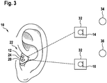
- Fig. 3 shows a further embodiment of the hearing device 10, which comprises a hearing aid 22 with solely an in-the-ear component 24, which provides the microphone 12 and the loudspeaker 20.
- the computing device 18 also may be provided in the in-the-ear component 24.
- the hearing aid 22 may be wireless communicatively connected with one or two devices 32, which provide the microphones 14, 16.
- the two microphones 14, 16 are provided by one mechanically connected component, such as a pen, a smartphone, etc.
- the microphone 14 is located near a desired sound source 34 and the microphone 16 is located near a disturb sound source 36.
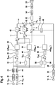
- Fig. 4 shows a diagram that illustrates a method that may be performed with the hearing aid 10. All the steps described in the following may be performed by the computing device 18.
- the outside channel sound signals S O1 and S O2 as well as the inside channel sound signal S I are demodulated by demodulators 38 into respective digital signals and after that transformed into the frequency domain.
- This transformation is performed by Fourier transformation blocks 40, which apply a fast Fourier transformation (FFT) onto the respective digitized signal S O1 , S O2 and S I .
- FFT fast Fourier transformation
- each signal S O1 , S O2 , S I may be cut into time frames, of for example 50 ⁇ s. These frames may be transformed into for example 100 Hz width frequency bands or bins, which for example cover the signals up to 20 kHz.
- a frequency band of a frame may be represented by a complex number after the transformation.
- the frequency bands of the respective signals after the transformation will be denoted with S O1,i (t j ), S O2,i (t j ), S I,i (t j ), where i indicates the frequency band and t j the time frame.
- the method is based on the assumption that the desired sound source 34 and disturb sound source 36 have different spectral information at different time points, i.e. that the amplitudes and the phases of the corresponding sound signals are different at different time points. Since the sound pressure fields of several sources 34, 36 may be added by superposition, also the spectral information is a sum of the components of the several sources 34, 36.
- the components of the disturb sound sources 36 for a sound signal in the ear channel may be subtracted, which results in a selective damping of these components in this sound signal.
- a desired signal S Des and a disturb signal S Dis are determined from the first and second outside channel sound signals S O1 , S O2 in the following way.
- the desired signal S Des is determined by filtering the second outside channel sound signal S O2 with a filter 42 and subtracting the filtered second outside channel sound signal S O2 from the first outside channel sound signal Soi.
- the desired signal S Des may be a beamformed signal, which is amplified towards a desired direction, i.e. the direction towards the desired sound source 34 and damped in an opposite direction. This damping form is also called cardioid shaped damping.
- the disturb signal S Dis may be a beamformed signal, which is damped towards the desired direction and amplified towards the opposite direction, as shown in Fig. 5B .
- the disturb signal S Dis may be determined by filtering the first outside channel sound signal S O1 with a filter 44 and subtracting the filtered first outside channel sound signal S O1 from the second outside channel sound signal S O2 .
- the filters 42, 44 may frequency dependent amplify the signal S O2 , for example by multiplying a frequency frame dependent constant to the value in each frequency band.
- the desired signal S Des and the disturb signal S Dis are determined in another way from the outer channel sound signals S O1 , S O2 .
- signal coherence and modulation of these signals may be used for separating the signals S Des and S Dis .
- S Des is simply set to S O1 and S Dis is simply set to S O2 .
- the disturb signal S Dis contains substantially the spectrum of the disturb source 36, i.e. which frequencies with amplitudes and phases are generated from the disturb source 36.
- the desired signal S Des contains substantially the spectrum of the desired source 34, i.e. which frequencies with amplitudes and phases are generated from the desired source 36.
- the results are values S Des,i (t j ) and S Dis,i (t j ).
- magnitude values m(S Dis,i (t j )) and m(S Des,i (t j )) are determined with the blocks 46.
- each magnitude value of a signal in a frequency band i may be a value depending on the signal energy in the frequency band i.
- S Des,i (t j ) and S Dis,i (t j ) are complex numbers, then their absolute value is proportional to the sound pressure and the square of the absolute value, which may be determined by multiplying the respective complex number with its conjugate, is proportional to the signal energy.
- the signal energy, the signal pressure or a function thereof may be used as magnitude value.
- the magnitude value m(S Des,i (t j )) of the desired signal (S Des ) and the magnitude value m(S Dis,i (t j )) of the disturb signal (S Dis ) may be averaged with a moving average, for example a weighted moving average. It also may be possible that a moving average is directly performed on the signals S Dis and S Des and that the magnitude values m(S Des,i (t j )), m(S Dis,i (t j )) are determined afterwards.
- a weight factor ⁇ is determined, which may be calculated for every time frame t j and every frequency band.
- the frequency band dependent weight factor ⁇ i (t j ) is determined by dividing the magnitude value m(S Des,i (t j )) of the desired signal S Des through a function of the magnitude value m(S Des,i (t j )) of the disturb signal S Dis . This function may be linear in the magnitude value m(S Des,i (t j )) and/or may comprise further summands.
- the weight factor ⁇ i (t j ) may be proportional to the magnitude value m(S Des,i (t j )) of the desired signal S Des divided through the magnitude value m(S Dis,i (t j )) of the disturb signal S Dis .
- ⁇ i t j ⁇ i * m S Des , i t j / m S Dis , i t j
- Such a weight factor ⁇ may be beneficial, when there is always noise in the disturb signal S Dis and a division by zero is not critical. Especially, when the weight factor ⁇ is compressed (see below), the spectrum of the adjusted signal S A is not altered, when the noise in the signal S Dis is low.
- the weight factor w may be multiplied with a frequency band dependent constant factor ⁇ i , which for example may weigh the damping of the weight factor per frequency band.
- the weight factor ⁇ i (t j ) may be proportional to the magnitude value m(S Des,i (t j )) of the desired signal S Des divided through the sum of the magnitude value m(S Des,i (t j )) of the desired signal S Des and the magnitude value m(S Dis,i (t j )) of the disturb signal S Dis .
- ⁇ i t j ⁇ i * m S Des , i t j / m S Des , i t j + m S Dis , i t j
- the noise reduced sound signal S A may then be determined by multiplying the inside channel sound signal S I with the weight factor ⁇ .
- S A , i t j ⁇ i t j * S I , i t j
- the contributions from the disturb sound source 36 are suppressed, which influences of the ear and the head of the user using the hearing device 10 are still present. This may result in a more natural hearing experience.
- the noise reduced sound signal S A may be further processed with a frequency dependent filter and/or amplification and/or compression, as shown with block 52.
- This filter and/or amplification and/or compression may be individually adjusted to the hearing deficiencies of the user.
- block 52 may provide further hearing aid functionality.
- the further processed sound signal may be transformed back with an inverse fast Fourier transformation (IFFT), may be modulated with block 56 and may be output by the loudspeaker 20.
- IFFT inverse fast Fourier transformation
- weight factor w is determined, but that two or more weight factors ⁇ ' are determined, which are based on different disturb signals S Dis '.
- a further disturb signal S Dis ' may be determined from the first and second outside channel sound signals S O1 , S O2 .
- the further disturb signal S Dis ' may be determined by applying a first filter 58 to the first outside channel sound signal S O1 and a second filter 60 to the second outside channel sound signal S O2 .
- both filtered signals may be subtracted from each other.
- the filters 58, 60 may operate like the filters 42, 44.
- the further disturb signal S Dis ' may be a beamformed signal as shown in Fig. 5C , which may have more than one desired direction and/or more than one disturb direction.
- weight factors also may be weighted relatively to each other via multiplication with respective constant factors ⁇ i (see above), which also then may be frequency independent.
- a frequency dependent correction factor h may be used for optimally weighting the frequency components of the weight factor w with respect to each other.
- a magnitude value m(S I,i (t j )) is determined. It also may be that before or after the magnitude value m(S I,i (t j )) is determined, either inside channel sound signal S I,i (t j ) or the magnitude value m(S I,i (t j )) is averaged with a moving average or a weighted moving average.
- the frequency band dependent and time frame dependent correction factor h i (t j ) is the determined by dividing the magnitude value m(S I,i (t j )) of the inside channel sound signal S I through the magnitude value of at least one of the desired and disturb sound signal S Des , S Dis .
- the correction factor h, its nominator and/or its denominator may be multiplied with further frequency band dependent factors ⁇ i , ⁇ i , which may model transfer functions between the position of the microphone 12 in the ear channel and the microphones 14, 16.
- the noise reduced sound signal S A is determined by multiplying the inside channel sound signal S I with the one or more weight factors ⁇ , ⁇ ' and the correction factor h.
- S A , i t j h i t j * ⁇ i t j * ⁇ i ′ t j * S I , i t j
- the one or more weight factors ⁇ , ⁇ ' and/or the correction factor h are restricted to a value range.
- the value range may be 0 to 1 or a subinterval therefrom.
- An example for this is shown in Fig. 4 with two compressors 62, each of which restricts the weight factors ⁇ and ⁇ '. It may be possible that such a compressor 62 is also applied to the correction factor h.
- the compressor 62 restricts the values h i (t j ), ⁇ i (t j ) * ⁇ i '(t j ) within the range. This may be possible with a cutoff, which sets values outside of the range to the respective bound of the range. However, it also may be possible to move values outside the value range within the value range in a more complicated manner.
- a compressor is applied to the product of the one or more weights and/or the correction factor h.
- the lower bound of the value range is greater than 0, such that no complete suppression of noise is possible.
- An upper bound of 1 may be beneficial, since in the case of no or nearly no noise, no distortion may take place.
Landscapes
- Engineering & Computer Science (AREA)
- Acoustics & Sound (AREA)
- Physics & Mathematics (AREA)
- Signal Processing (AREA)
- Health & Medical Sciences (AREA)
- Human Computer Interaction (AREA)
- Audiology, Speech & Language Pathology (AREA)
- Quality & Reliability (AREA)
- Computational Linguistics (AREA)
- Multimedia (AREA)
- General Health & Medical Sciences (AREA)
- Neurosurgery (AREA)
- Otolaryngology (AREA)
- Soundproofing, Sound Blocking, And Sound Damping (AREA)
Abstract
Description
- The invention relates to a method, a computer program and a computer-readable medium for reducing noise in a sound signal of a hearing device.
- Hearing aids are wearable devices, which are designed to compensate a hearing loss of the person or user wearing the hearing aid. It may be that sound signals acquired by the hearing aid are frequency dependent amplified, which would be too silent to be heard by the user. This frequency dependent amplification may be individually adjusted to the hearing loss of the user. Furthermore, it may be possible that specific components of the sound signals, such as speech or desired sound sources, are amplified with respect to disturb sound.
- There are basically two methods, how such desired sound sources may be amplified.
- In the first method, two microphones are used, and the sound signals from the two microphones are processed in such a way, that a direction dependent amplification is achieved. This is usually called beamforming. Sound from a specific direction, usually to the front of the user, is amplified, which sound from other directions is damped. It is known that with the aid of beamforming, the signal-to-noise ratio of a hearing aid may be improved by 3 to 8 dB with respect to omnidirectional sound processing. Beamforming may be performed in the time domain and in the frequency domain and may be controlled differently in different frequency bands.
- The second method tries to filter the energy from disturb signals. The sound spectrum of a disturb source is estimated, for example during a speech pause, in which only the disturb source is present. After the speech pause, the spectrum may be subtracted from the overall sound signal. However, this method is usually only applicable in situations with only slow varying spectral information. Furthermore, artifacts, like so called "musical noise", may be generated, which reduce the quality of the desired sound signal.
- In general, there are two types of hearing aids, which are used by persons with hearing losses.
- The first type is called behind-the-ear hearing aids, which are carried behind the ear. These behind-the-ear hearing aids usually have two or more microphones provided in its housing, which signals may be used for beamforming. Behind-the-ear hearing aids may have the advantages that an ear channel insert (such as an otoplastic) may be designed acoustically more closed or more opened, as desired.
- The second type of hearing aids is called in-the-ear or in-the-channel hearing aids, which are completely or nearly completely carried in the ear channel. These types of hearing aids may have the advantage that their microphone is positioned at the entrance of the ear channel, such that it acquires sound signals, which have already been formed by the ear and other components of the head, which results to a rather natural hearing experience.
- In particular, the spectral information from the concha is lost for behind-the-ear hearing aids, which spectral information is important for distinguishing the direction of a sound source. Furthermore, the spectral information plays a role in elevation perception, externalization, and a natural spatial perception.
-
US 2010/0 329 492 A1 relates to a method for reducing noise in an input signal of a hearing aid, in which the sound signals from two microphones are transformed into a desired signal and a disturb signal. The disturb signal may be frequency depended amplified with a weight function based on a Wiener filter. - It is an objective of the invention to provide a hearing device, with a natural hearing experience and a good noise reduction.
- This objective is achieved by the subject-matter of the independent claims. Further exemplary embodiments are evident from the dependent claims and the following description.
- A first aspect of the invention relates to a method for reducing noise in a sound signal of a hearing device. The method may be performed automatically by a computing device of the hearing aid. The hearing device may be a hearing aid wearable by a user of the hearing device and/or may comprise further components, which may be situated remote from a component at the ear or in the ear of the user.
- According to an embodiment of the invention, the method comprises: receiving an inside channel sound signal from a microphone in an ear channel of a user of the hearing device, a first outside channel sound signal from a microphone outside of the ear channel and a second outside channel sound signal from a further microphone outside of the ear channel. In a first step of the method, at least three sound signals may be acquired. The inside channel sound signal may be acquired inside the ear channel. The first and second outside channel sound signals may be acquired outside of the ear channel, for example with a component of the hearing device behind the ear.
- It has to be noted that "in the ear channel" may mean a position (such that of a microphone) at the entrance of the ear channel or between the entrance and the eardrum.
- A sound signal in general may be a signal from a microphone that is digitized by a computing device of the hearing aid for further processing. It may be that the sound signals mentioned above are transformed into the frequency domain, for example with a FFT (fast Fourier transform).
- According to an embodiment of the invention, the method further comprises: determining a desired signal from the first and second outside channel sound signals and a disturb signal from the first and second outside channel sound signals. In a further step of the method, the sound signals from the first and second microphone outside of the ear channel are transformed into signals, which are indicative of a desired sound source and a disturb sound source.
- In general, the desired signal may be indicative of a desired sound source and/or the disturb signal may be indicative of one or more disturb sound sources. The desired signal may be a signal comprising more spectral information from a desired sound source as from one or more disturb sources. Here, spectral information may comprise frequency band dependent amplitudes and/or phases of the sound signal. For example, the desired sound signal and the disturb signal may be determined by adding and/or subtracting the first and second outside channel sound signals, which may be filtered before adding and/or subtracting. The desired signal and the disturb signal may be determined by beamforming.
- It also may be possible that the first outside channel sound signal is acquired with a microphone nearer to a desired sound source as the microphone, which acquires the second outside channel sound signal and which is nearer to a disturb sound source.
- According to an embodiment of the invention, the method further comprises: determining a frequency band dependent weight factor by dividing a magnitude value of the desired signal in a frequency band through at least a magnitude value of the disturb signal in the frequency band. In the next step of the method, a weight factor for multiplication with the inside channel sound signal may be determined solely from the desired signal and the disturb signal. The weight factor for reducing the disturb sound may be determined independently from the sound signal in the ear channel, which may result in a good signal-to-noise ratio.
- The weight factor is frequency band dependent, i.e. there may be a value for the weight factor for each frequency band that is processed with the method. For example, the respective sound signals may be Fourier transformed into frequency bins, each of which may be seen as a frequency band. Then, for every frequency bin, the weight factor may be determined.
- The weight factor is determined from magnitude values of the desired signal and disturb signal. A magnitude value may be a (real) value that only depends on the amplitude of the sound signal and not its phase. For example, when the sound signals are provided with complex numbers, the magnitude value may be a function of the absolute value of the complex numbers.
- The magnitude value may be a function of the sound pressure of the sound signal in the frequency band, which is equivalent to an absolute value of a complex valued sound signal, or may be a function of the energy of the sound signal in the frequency band, which is equivalent to a square of the absolute value of a complex valued sound signal.
- The weight value may be determined by dividing the magnitude value of the desired signal through at least the magnitude value of the disturb signal, i.e. through a denominator comprising the magnitude of the disturb signal. As will be mentioned below, the denominator may comprise further factors and/or summands.
- According to an embodiment of the invention, the method further comprises: determining a frequency band dependent correction factor by dividing a magnitude value of the inside channel sound signal in a frequency band through a magnitude value of at least one of the disturb signal and desired signal. In a further step of the method, a correction factor is determined, which may account for the different sound levels of the inside channel sound signal and the outside channel sound signals. The correction factor may be determined by dividing a magnitude value of the inside channel sound signal through the magnitude value of the disturb signal, the desired signal or a sum thereof. The magnitude value of the inside channel sound signal may be determined as the magnitude values for the other signals as described above.
- According to an embodiment of the invention, the method further comprises: generating a noise reduced sound signal by multiplying the inside channel sound signal with the weight factor and optionally the correction factor. In the end, the weight factor and optionally the correction factor are used for adjusting the inside channel sound signal. Again, this calculation is performed per frequency band. It has to be noted that the weight factor and the correction factor are real values, which by multiplication only adjusts the amplitude of the inside channel sound signal but not its phase. Thus, the phase information of the inside channel sound signal is not changed.
- The adjusted inside channel sound signal may be further processed by the hearing device to compensate for hearing losses of the user. For example, the adjusted inside channel sound signal may be frequency band dependent amplified with preset amplification factors individually chosen for the user.
- With the method, hearing devices may be provided with the ability to modify spectral acoustic information in the ear channel of a user in such a way, that disturbing sound sources are damped but such that acoustic features (cues) of desired sound sources are maintained. These acoustic features may comprise a filtering of the sound by the concha. This may have positive effects on a spatial resolution of sound sources, an externalization, a distance perception, a source wideness and problems with exchange of front and back.
- According to an embodiment of the invention, the frequency band dependent weight factor is the magnitude value of the desired signal in the frequency band divided through the magnitude value of the disturb signal in the frequency band. This may be beneficial, when the disturb signal is noise and therefore never equal to 0. In combination with a restriction of the weight factor to a range with upper border equal to 1, for a small disturb signal, the weight factor becomes 1 and the inside channel sound signal is not modified. Furthermore, musical noise, which may be generated by other weight functions during fast changing situations, may be avoided.
- According to an embodiment of the invention, the frequency band dependent weight factor is the magnitude value of the desired signal in the frequency band divided through the sum of the magnitude value of the desired signal in the frequency band and the magnitude value of the disturb signal in the frequency band. Such a weight factor may model a Wiener filter, which also may effectively remove contributions of the disturb signal from the inside channel sound signal. This weight factor may be used, when the weight factor is not restricted to a range and/or compressed.
- According to an embodiment of the invention, the method further comprises: determining at least one further disturb signal from the first and second outside channel sound signals; and multiplying the noise reduced sound signal with at least one further frequency band dependent weight factor, which is determined from the further disturb signal and the desired signal. It is possible that not only one but two or more disturb signals are used for adjusting the inside channel sound signal. Every disturb signal may be used for determining a weight factor as described above. All these weight factors may be multiplied with the inside channel sound signal. For example, for different disturb sound sources (which may lie in different directions), different disturb signals may be used.
- According to an embodiment of the invention, the magnitude value of the desired signal and the magnitude value of the disturb signal are averaged with a moving average before the frequency band dependent weight factor is determined from them. The weight factors and/or the correction factors may be determined repeatedly for short time intervals, in which the respective signals are transformed into the frequency domain. It may be that the magnitude values input into the weight factor and/or the correction factors are averaged for several of these time intervals, for example with a moving average. This also may reduce musical noise.
- According to an embodiment of the invention, the weight factor is multiplied with a frequency band dependent factor. It may be that for further optimizing, the weight factor is adjusted with constant frequency dependent factors. For example, specific frequency bands may be damped in general more strongly as others.
- According to an embodiment of the invention, the correction factor is multiplied with a frequency band dependent factor. For example, with such a constant factor, the transfer function between different microphone positions inside the ear channel and outside the ear channel may be modeled. It also may be that the nominator and/or denominator of the correction factor may be multiplied with constant frequency dependent factors, for example for modeling such transfer functions.
- According to an embodiment of the invention, the method further comprises: restricting the weight factor and/or the correction factor to a value range. In general, these factors or the product of these factors may be restricted to values bigger than a lower bound and/or to values smaller than an upper bound. This may be achieved by setting values greater and/or smaller than the respective bound to the respective bound.
- According to an embodiment of the invention, a compressor function is applied to the weight factor and/or the correction factor, which moves the values of the weight factor and/or the correction factor within the value range. It also may be that the restriction to a value range may be achieved by a function, changes the values of the weight factor and/or correction factor in such a way, that after the transformation, no values lie outside the desired value range any more.
- According to an embodiment of the invention, the value range is within 0 to 1. A lower bound of the value range may be 0 or greater. An upper bound of the value range may be 1 or lower.
- According to an embodiment of the invention, the desired signal is a beamformed signal, which is amplified towards a desired direction and damped in an opposite direction and/or the disturb signal is a beamformed signal, which is damped towards the desired direction and amplified towards the opposite direction. One possibility of transforming the desired signal and the disturb signal is by beamforming. In this case, it may be assumed that the desired sound source is in the desired direction, such as a front direction of the user and the disturb sound sources are located in another direction. This may be modeled with a beamformed disturb signal in the opposite direction, such as the back direction of the user.
- According to an embodiment of the invention, the desired signal is determined by filtering the second outside channel sound signal and subtracting the filtered second outside channel sound signal from the first outside channel sound signal. Also, the disturb signal may be determined by filtering the first outside channel sound signal and subtracting the filtered first outside channel sound signal from the second outside channel sound signal. A beamformed signal may be determined from the sound signals of two different microphones by filtering one of the sound signals of one of the microphones with a frequency (band) dependent filter and subtracting the other signal. In this case, filtering may comprise frequency (band) dependent damping of the respective signal. It has to be noted that not only one but further disturb signals may be determined by filtering both outside channel sound signals with different filters.
- According to an embodiment of the invention, the magnitude value of a signal in a frequency band is a value depending on an energy of the signal in the frequency band. A magnitude value of the desired signal, the disturb signal and or the first and second outside channel sound signal may be determined per frequency band, such as for a specific frequency bin. From the signal components in the frequency band and/or bin, an energy of the signal in this band and/or bin may be determined. The magnitude value then may be a function of this energy.
- In the case, these signals are encoded with complex numbers, the energy may be based on the square of the absolute values of the complex numbers.
- It may be that the magnitude value of a signal in a frequency band is the signal energy of the respective signal in the frequency band. In this case, the magnitude value may be determined by multiplying the corresponding complex numbers with its conjugate.
- It also may be that the magnitude value of a signal in the frequency band is the sound pressure of the respective signal in the frequency band. The sound pressure is proportional to a square root of the energy and/or may be determined directly from the absolute value of the complex numbers used for encoding the respective signal.
- Further aspects of the invention relate to a computer program for reducing noise in a signal of a hearing device, which, when being executed by a processor, is adapted to carry out the steps of the method as described in the above and in the following as well as to a computer-readable medium, in which such a computer program is stored.
- For example, the computer program may be executed in a processor of a hearing aid, which, for example, may be carried by the user behind the ear. The computer-readable-medium may be a memory of this hearing aid.
- In general, a computer-readable medium may be a floppy disk, a hard disk, an USB (Universal Serial Bus) storage device, a RAM (Random Access Memory), a ROM (Read Only Memory), an EPROM (Erasable Programmable Read Only Memory) or a FLASH memory. A computer-readable medium may also be a data communication network, e.g. the Internet, which allows downloading a program code. The computer-readable medium may be a non-transitory or transitory medium.
- A further aspect of the invention relates to a hearing device, which comprises a first microphone adapted for being put in an ear channel of a user; a second microphone adapted for being arranged outside of the ear channel, a third microphone adapted for being arranged outside of the ear channel; and a computing device adapted for performing the method as described in the above and in the following.
- The three microphones may be mechanically interconnected within one device. However, it also may be possible that the microphone on the ear channel is provided by a hearing aid and the other two microphones outside of the ear channel are provided by a further device, which is mechanically separated from the hearing aid.
- According to an embodiment of the invention, the hearing device is a hearing aid adapted for being carried at an ear of the user, which comprises the first microphone in a device component for being put in the ear channel and which comprises the second and third microphone in a device component behind the ear. For example, the hearing aid may have an open insert for the ear channel, which carries the in-the-ear microphone and which has an opening, such that sound from the environment can enter the ear channel. The insert may be connected to a device component behind the ear, which carries the two further microphones.
- According to an embodiment of the invention, the hearing device comprises a hearing aid which comprises the first microphone in a device component for being put in the ear channel. The hearing device comprises a further device communicatively interconnected with the hearing aid and comprising the second and/or third microphone. In this case, the hearing aid may be an in-the-ear hearing aid, which is completely provided in the ear channel. The further device may be a component behind the ear, which may or may not be directly mechanically interconnected with the in-the-ear hearing aid. However, it also may be that the further device is a pen with two microphones, a smartphone, etc., which may be carried by the user in his hands.
- It has to be understood that features of the method as described in the above and in the following may be features of the computer program, the computer-readable medium and the hearing device as described in the above and in the following, and vice versa.
- These and other aspects of the invention will be apparent from and elucidated with reference to the embodiments described hereinafter.
- Below, embodiments of the present invention are described in more detail with reference to the attached drawings.
-
Fig. 1 schematically shows a hearing device according to an embodiment of the invention. -
Fig. 2 schematically shows a hearing device according to a further embodiment of the invention. -
Fig. 3 schematically shows a hearing device according to a further embodiment of the invention. -
Fig. 4 shows a diagram illustrating a method for reducing noise in a sound signal of a hearing device according to an embodiment of the invention. -
Fig. 5A, 5B and 5C are diagrams illustrating beamformed signals. - The reference symbols used in the drawings, and their meanings, are listed in summary form in the list of reference symbols. In principle, identical parts are provided with the same reference symbols in the figures.
-
Fig. 1 shows ahearing device 10, which comprises an in-the-ear microphone 12, which is adapted for being arranged in the ear channel of a user, and two outside-the-ear microphones - A
computing device 18 receives sound signals SI, SO1, SO2 from themicrophones loudspeaker 20 to be heard by the user. - In particular, the first outside channel sound signal SO1 and the second outside channel sound signal SO2 are used for determining a desired signal and one or more disturb signals from which a frequency dependent factor is determined, which is multiplied with the inside channel sound signal SI for generating the adjusted sound signal SA.
-
Fig. 2 shows an embodiment of thehearing device 10, which is ahearing aid 22, which comprises an in-the-channel component 24 and a behind-the-ear component 26. The behind-the-ear component 26 provides the twomicrophones housing 28. Thishousing 28 also may accommodate thecomputing device 18. The in-the-channel component 24, which is carried substantially or completely inside the ear channel, provides themicrophone 12, for example at an outside end, and theloudspeaker 20, for example at an inside end. It has to be noted that themicrophone 12 may be arranged inside the ear channel or at an outer end, i.e. the entrance of the ear channel. - Both
components communication line 30, which is used for transmitting the signals SI and SA. -
Fig. 3 shows a further embodiment of thehearing device 10, which comprises ahearing aid 22 with solely an in-the-ear component 24, which provides themicrophone 12 and theloudspeaker 20. Thecomputing device 18 also may be provided in the in-the-ear component 24. Thehearing aid 22 may be wireless communicatively connected with one or twodevices 32, which provide themicrophones microphones microphone 14 is located near a desiredsound source 34 and themicrophone 16 is located near a disturbsound source 36. -
Fig. 4 shows a diagram that illustrates a method that may be performed with thehearing aid 10. All the steps described in the following may be performed by thecomputing device 18. - For performing the following calculations, the outside channel sound signals SO1 and SO2 as well as the inside channel sound signal SI are demodulated by
demodulators 38 into respective digital signals and after that transformed into the frequency domain. This transformation is performed by Fourier transformation blocks 40, which apply a fast Fourier transformation (FFT) onto the respective digitized signal SO1, SO2 and SI. - For example, each signal SO1, SO2, SI may be cut into time frames, of for example 50 µs. These frames may be transformed into for example 100 Hz width frequency bands or bins, which for example cover the signals up to 20 kHz. A frequency band of a frame may be represented by a complex number after the transformation.
- In the following, the frequency bands of the respective signals after the transformation will be denoted with SO1,i(tj), SO2,i(tj), SI,i(tj), where i indicates the frequency band and tj the time frame.
- In general, the method is based on the assumption that the desired
sound source 34 and disturbsound source 36 have different spectral information at different time points, i.e. that the amplitudes and the phases of the corresponding sound signals are different at different time points. Since the sound pressure fields ofseveral sources several sources - When known, the components of the disturb
sound sources 36 for a sound signal in the ear channel may be subtracted, which results in a selective damping of these components in this sound signal. - As shown in
Fig. 4 , a desired signal SDes and a disturb signal SDis are determined from the first and second outside channel sound signals SO1, SO2 in the following way. - The desired signal SDes is determined by filtering the second outside channel sound signal SO2 with a
filter 42 and subtracting the filtered second outside channel sound signal SO2 from the first outside channel sound signal Soi. As shown inFig. 5A , the desired signal SDes may be a beamformed signal, which is amplified towards a desired direction, i.e. the direction towards the desiredsound source 34 and damped in an opposite direction. This damping form is also called cardioid shaped damping. - Also, the disturb signal SDis may be a beamformed signal, which is damped towards the desired direction and amplified towards the opposite direction, as shown in
Fig. 5B . The disturb signal SDis may be determined by filtering the first outside channel sound signal SO1 with afilter 44 and subtracting the filtered first outside channel sound signal SO1 from the second outside channel sound signal SO2. - The
filters - It is possible that the desired signal SDes and the disturb signal SDis are determined in another way from the outer channel sound signals SO1, SO2. For example, signal coherence and modulation of these signals may be used for separating the signals SDes and SDis. It also may possible that, as in the case of
Fig. 3 with twomicrophone devices 32 with one nearer to therespective sound source - In general, the disturb signal SDis contains substantially the spectrum of the disturb
source 36, i.e. which frequencies with amplitudes and phases are generated from the disturbsource 36. Analogously, the desired signal SDes contains substantially the spectrum of the desiredsource 34, i.e. which frequencies with amplitudes and phases are generated from the desiredsource 36. - It has to be noted that, since both sound signals SO1 and SO2 have been acquired outside of the ear channel and/or outside of the ear, the signals SDes and SDis do not contain components of the filtering of the ear and head of the user.
- Since the previous calculations may be performed per time frame tj and per frequency band i, the results are values SDes,i(tj) and SDis,i(tj).
- From these values, magnitude values m(SDis,i(tj)) and m(SDes,i(tj)) are determined with the
blocks 46. In general, each magnitude value of a signal in a frequency band i may be a value depending on the signal energy in the frequency band i. When the values SDes,i(tj) and SDis,i(tj) are complex numbers, then their absolute value is proportional to the sound pressure and the square of the absolute value, which may be determined by multiplying the respective complex number with its conjugate, is proportional to the signal energy. The signal energy, the signal pressure or a function thereof may be used as magnitude value. - The magnitude value m(SDes,i(tj)) of the desired signal (SDes) and the magnitude value m(SDis,i(tj)) of the disturb signal (SDis) may be averaged with a moving average, for example a weighted moving average. It also may be possible that a moving average is directly performed on the signals SDis and SDes and that the magnitude values m(SDes,i(tj)), m(SDis,i(tj)) are determined afterwards.
- From the magnitude values m(SDes,i(tj)), m(SDis,i(tj)), a weight factor ω is determined, which may be calculated for every time frame tj and every frequency band. In general, the frequency band dependent weight factor ωi(tj) is determined by dividing the magnitude value m(SDes,i(tj)) of the desired signal SDes through a function of the magnitude value m(SDes,i(tj)) of the disturb signal SDis. This function may be linear in the magnitude value m(SDes,i(tj)) and/or may comprise further summands.
- As a first example, the weight factor ωi(tj) may be proportional to the magnitude value m(SDes,i(tj)) of the desired signal SDes divided through the magnitude value m(SDis,i(tj)) of the disturb signal SDis.

- Such a weight factor ω may be beneficial, when there is always noise in the disturb signal SDis and a division by zero is not critical. Especially, when the weight factor ω is compressed (see below), the spectrum of the adjusted signal SA is not altered, when the noise in the signal SDis is low.
- As also shown in the above formula, the weight factor w may be multiplied with a frequency band dependent constant factor αi, which for example may weigh the damping of the weight factor per frequency band.
- It also may be possible to determine the weight factor w with a Wiener filter. In this case, the weight factor ωi(tj) may be proportional to the magnitude value m(SDes,i(tj)) of the desired signal SDes divided through the sum of the magnitude value m(SDes,i(tj)) of the desired signal SDes and the magnitude value m(SDis,i(tj)) of the disturb signal SDis.

- The noise reduced sound signal SA may then be determined by multiplying the inside channel sound signal SI with the weight factor ω.

- In the signal SA, the contributions from the disturb
sound source 36 are suppressed, which influences of the ear and the head of the user using thehearing device 10 are still present. This may result in a more natural hearing experience. - The noise reduced sound signal SA may be further processed with a frequency dependent filter and/or amplification and/or compression, as shown with
block 52. This filter and/or amplification and/or compression may be individually adjusted to the hearing deficiencies of the user. In general, block 52 may provide further hearing aid functionality. - In
block 54, the further processed sound signal may be transformed back with an inverse fast Fourier transformation (IFFT), may be modulated withblock 56 and may be output by theloudspeaker 20. - It may be possible that not only one weight factor w is determined, but that two or more weight factors ω' are determined, which are based on different disturb signals SDis'.
- As shown in
Fig. 4 , a further disturb signal SDis' may be determined from the first and second outside channel sound signals SO1, SO2. The further disturb signal SDis' may be determined by applying afirst filter 58 to the first outside channel sound signal SO1 and asecond filter 60 to the second outside channel sound signal SO2. For generating the further disturb signal SDis', both filtered signals may be subtracted from each other. Thefilters filters Fig. 5C , which may have more than one desired direction and/or more than one disturb direction. - Analogously to the weight signal ω, a further frequency band dependent weight factor ω' may be determined from the further disturb signal SDis and the desired signal SDes. Also the weight factor ω' may be multiplied to the inside channel sound signal SI for determining the noise reduced sound signal SA

- Note that the weight factors also may be weighted relatively to each other via multiplication with respective constant factors αi (see above), which also then may be frequency independent.
- As further shown in
Fig. 4 , it is also possible to additionally multiply a frequency dependent correction factor h to the one or more weight factors ω, ω'. For example, the correction factor h may be used for optimally weighting the frequency components of the weight factor w with respect to each other. - For determining the factor h, also from the FFT transformed inside channel sound signal SI,i(tj), a magnitude value m(SI,i(tj)) is determined. It also may be that before or after the magnitude value m(SI,i(tj)) is determined, either inside channel sound signal SI,i(tj) or the magnitude value m(SI,i(tj)) is averaged with a moving average or a weighted moving average.
- The frequency band dependent and time frame dependent correction factor hi(tj) is the determined by dividing the magnitude value m(SI,i(tj)) of the inside channel sound signal SI through the magnitude value of at least one of the desired and disturb sound signal SDes, SDis.
- Possible implementations of the correction factor h are


- The correction factor h, its nominator and/or its denominator may be multiplied with further frequency band dependent factors βi, γi, which may model transfer functions between the position of the
microphone 12 in the ear channel and themicrophones - In this case, the noise reduced sound signal SA is determined by multiplying the inside channel sound signal SI with the one or more weight factors ω, ω' and the correction factor h.

- A further possibility is that the one or more weight factors ω, ω' and/or the correction factor h are restricted to a value range. For example, the value range may be 0 to 1 or a subinterval therefrom. An example for this is shown in
Fig. 4 with twocompressors 62, each of which restricts the weight factors ω and ω'. It may be possible that such acompressor 62 is also applied to the correction factor h. - The
compressor 62 restricts the values hi(tj), ωi(tj) * ωi'(tj) within the range. This may be possible with a cutoff, which sets values outside of the range to the respective bound of the range. However, it also may be possible to move values outside the value range within the value range in a more complicated manner. - Alternatively, it is possible that a compressor is applied to the product of the one or more weights and/or the correction factor h.
- It may be that the lower bound of the value range is greater than 0, such that no complete suppression of noise is possible. An upper bound of 1 may be beneficial, since in the case of no or nearly no noise, no distortion may take place.
- While the invention has been illustrated and described in detail in the drawings and foregoing description, such illustration and description are to be considered illustrative or exemplary and not restrictive; the invention is not limited to the disclosed embodiments. Other variations to the disclosed embodiments can be understood and effected by those skilled in the art and practising the claimed invention, from a study of the drawings, the disclosure, and the appended claims. In the claims, the word "comprising" does not exclude other elements or steps, and the indefinite article "a" or "an" does not exclude a plurality. A single processor or controller or other unit may fulfill the functions of several items recited in the claims. The mere fact that certain measures are recited in mutually different dependent claims does not indicate that a combination of these measures cannot be used to advantage. Any reference signs in the claims should not be construed as limiting the scope.
-
- 10
- hearing device
- 12
- in-the-ear microphone
- 14
- outside-the-ear microphone
- 16
- outside-the-ear microphone
- 18
- computing device
- 20
- loudspeaker
- SI
- inside channel sound signal
- SO1
- first outside channel sound signal
- SO2
- second outside channel sound signal
- 22
- hearing aid
- 24
- in-the-channel component
- 26
- behind-the-ear component
- 28
- housing
- 30
- communication line
- 32
- microphone device
- 36
- demodulator
- 40
- FFT block
- 42
- filter
- 44
- filter
- SDes
- desired signal
- SDis
- disturb signal
- SDis'
- further disturb signal
- 46
- magnitude value block
- m(SDes)
- magnitude value of desired signal
- m(SDis)
- magnitude value of disturb signal
- m(SI)
- magnitude value of inside channel sound signal
- m(SDis')
- magnitude value of further disturb signal
- 48
- moving average block
- ω
- weight factor
- ω'
- further weight factor
- h
- correction factor
- 52
- hearing aid function block
- 54
- IFFT block
- 56
- modulator
- 58
- filter
- 60
- filter
- 62
- compressor
Claims (15)
- A method for reducing noise in a sound signal of a hearing device (10), the method comprising:receiving an inside channel sound signal (SI) from a first microphone (12) in an ear channel of a user of the hearing device (10), a first outside channel sound signal (SO1) from a second microphone (14) outside of the ear channel and a second outside channel sound signal (SO2) from a third microphone (16) outside of the ear channel;determining a desired signal (SDes) and a disturb signal (SDis) from the first and second outside channel sound signals (SO1, SO2);determining a frequency band dependent weight factor (ω) by dividing a magnitude value of the desired signal (SDes) in a frequency band through at least a magnitude value of the disturb signal (SDis) in the frequency band;generating a noise reduced sound signal (SA) by multiplying the inside channel sound signal (SI) with the weight factor (ω).
- The method of claim 1,
wherein the frequency band dependent weight factor (ω) is the magnitude value of the desired signal (SDes) in the frequency band divided through the magnitude value of the disturb signal (SDis) in the frequency band. - The method of claim 1,
wherein the frequency band dependent weight factor (ω) is the magnitude value of the desired signal (SDes) in the frequency band divided through the sum of the magnitude value of the desired signal (SDes) in the frequency band and the magnitude value of the disturb signal (SDis) in the frequency band. - The method of one of the previous claims, further comprising:determining a frequency band dependent correction factor (h) by dividing a magnitude value of the inside channel sound signal (SI) in a frequency band through a magnitude value of at least one of the desired signal (SDes) and disturb signal (SDis) in the frequency band;generating the noise reduced sound signal (SA) by multiplying the inside channel sound signal (SI) with the weight factor (ω) and the correction factor (h).
- The method of one of the previous claims, further comprising:determining at least one further disturb signal (SDis') from the first and second outside channel sound signals (SO1, SO2);multiplying the noise reduced sound signal (SA) with at least one further frequency band dependent weight factor (ω'), which is determined from the further disturb signal (SDis) and the desired signal (SDes).
- The method of one of the previous claims,
wherein the magnitude value of the desired signal (SDes) and the magnitude value of the disturb signal (SDis) are averaged with a moving average (50) before the frequency band dependent weight factor (ω) is determined from them. - The method of one of the previous claims, further comprising:restricting the weight factor (ω) and/or the correction factor (h) to a value range;wherein a compressor function (62) is applied to the weight factor (ω) and/or the correction factor (h), which moves the values of the weight factor (ω) and/or the correction factor (h) within the value range;wherein the value range is within 0 to 1.
- The method of one of the previous claims,
wherein the desired signal (SDes) is a beamformed signal, which is amplified towards a desired direction and damped in an opposite direction;
wherein the disturb signal (SDis) is a beamformed signal, which is damped towards the desired direction and amplified towards the opposite direction. - The method of one of the previous claims,
wherein the desired signal (SDes) is determined by filtering the second outside channel sound signal (S02) and subtracting the filtered second outside channel sound signal (SO2) from the first outside channel sound signal (SO1);
wherein the disturb signal (SDis) is determined by filtering the first outside channel sound signal (SO1) and subtracting the filtered first outside channel sound signal (SO1) from the second outside channel sound signal (SO2). - The method of one of the previous claims,
wherein the magnitude value of a signal in a frequency band is a value depending on an energy of the signal in the frequency band; or
wherein the magnitude value of a signal in a frequency band is the signal energy of the respective signal in the frequency band; or
wherein the magnitude value of a signal in the frequency band is the sound pressure of the respective signal in the frequency band. - A computer program for reducing noise in a signal of a hearing device (10), which, when being executed by a processor, is adapted to carry out the steps of the method of one of claims 1 to 10.
- A computer-readable medium, in which a computer program according to claim 11 is stored.
- A hearing device (10), comprising:a first microphone (12) adapted for being put in an ear channel of a user of the hearing device (10);a second microphone (14) adapted for being arranged outside of the ear channel;a third microphone (16) adapted for being arranged outside of the ear channel;a computing device (18) adapted for performing the method of one of claims 1 to 10.
- The hearing device (10) of claim 13,
wherein the hearing device (10) is a hearing aid (22) adapted for being carried at an ear of the user, which comprises the first microphone (12) in a device component (24) for being put in the ear channel and which comprises the second and third microphone (14, 16) in a device component (26) behind the ear. - The hearing device (10) of claim 13,
wherein the hearing device (10) comprises a hearing aid (22) which comprises the first microphone (12) in a device component (24) for being put in the ear channel;
wherein the hearing device (10) comprises a further device (32) communicatively interconnected with the hearing aid (22) and comprising the second microphone (14) and/or third microphone (16).
Priority Applications (2)
| Application Number | Priority Date | Filing Date | Title |
|---|---|---|---|
| DK17209252.0T DK3503581T3 (en) | 2017-12-21 | 2017-12-21 | NOISE REDUCTION IN AN AUDIO SIGNAL FOR A HEARING DEVICE |
| EP17209252.0A EP3503581B1 (en) | 2017-12-21 | 2017-12-21 | Reducing noise in a sound signal of a hearing device |
Applications Claiming Priority (1)
| Application Number | Priority Date | Filing Date | Title |
|---|---|---|---|
| EP17209252.0A EP3503581B1 (en) | 2017-12-21 | 2017-12-21 | Reducing noise in a sound signal of a hearing device |
Publications (2)
| Publication Number | Publication Date |
|---|---|
| EP3503581A1 true EP3503581A1 (en) | 2019-06-26 |
| EP3503581B1 EP3503581B1 (en) | 2022-03-16 |
Family
ID=60702465
Family Applications (1)
| Application Number | Title | Priority Date | Filing Date |
|---|---|---|---|
| EP17209252.0A Active EP3503581B1 (en) | 2017-12-21 | 2017-12-21 | Reducing noise in a sound signal of a hearing device |
Country Status (2)
| Country | Link |
|---|---|
| EP (1) | EP3503581B1 (en) |
| DK (1) | DK3503581T3 (en) |
Cited By (3)
| Publication number | Priority date | Publication date | Assignee | Title |
|---|---|---|---|---|
| CN112309110A (en) * | 2019-11-05 | 2021-02-02 | 戚建民 | Congestion detection system based on big data communication |
| US20220038828A1 (en) * | 2020-07-29 | 2022-02-03 | Sivantos Pte. Ltd. | Method for directional signal processing for a hearing aid and hearing system |
| CN114598981A (en) * | 2022-05-11 | 2022-06-07 | 武汉左点科技有限公司 | Method and device for suppressing internal disturbance of hearing aid |
Citations (7)
| Publication number | Priority date | Publication date | Assignee | Title |
|---|---|---|---|---|
| JP2003044087A (en) * | 2001-08-03 | 2003-02-14 | Matsushita Electric Ind Co Ltd | Noise suppression device, noise suppression method, voice identification device, communication device, and hearing aid |
| US20080260175A1 (en) * | 2002-02-05 | 2008-10-23 | Mh Acoustics, Llc | Dual-Microphone Spatial Noise Suppression |
| EP2088802A1 (en) * | 2008-02-07 | 2009-08-12 | Oticon A/S | Method of estimating weighting function of audio signals in a hearing aid |
| US20100046775A1 (en) * | 2008-05-09 | 2010-02-25 | Andreas Tiefenau | Method for operating a hearing apparatus with directional effect and an associated hearing apparatus |
| US20100329492A1 (en) | 2008-02-05 | 2010-12-30 | Phonak Ag | Method for reducing noise in an input signal of a hearing device as well as a hearing device |
| EP2806660A1 (en) * | 2013-05-22 | 2014-11-26 | GN Resound A/S | A hearing aid with improved localization |
| EP2849462A1 (en) * | 2013-09-17 | 2015-03-18 | Oticon A/s | A hearing assistance device comprising an input transducer system |
-
2017
- 2017-12-21 DK DK17209252.0T patent/DK3503581T3/en active
- 2017-12-21 EP EP17209252.0A patent/EP3503581B1/en active Active
Patent Citations (7)
| Publication number | Priority date | Publication date | Assignee | Title |
|---|---|---|---|---|
| JP2003044087A (en) * | 2001-08-03 | 2003-02-14 | Matsushita Electric Ind Co Ltd | Noise suppression device, noise suppression method, voice identification device, communication device, and hearing aid |
| US20080260175A1 (en) * | 2002-02-05 | 2008-10-23 | Mh Acoustics, Llc | Dual-Microphone Spatial Noise Suppression |
| US20100329492A1 (en) | 2008-02-05 | 2010-12-30 | Phonak Ag | Method for reducing noise in an input signal of a hearing device as well as a hearing device |
| EP2088802A1 (en) * | 2008-02-07 | 2009-08-12 | Oticon A/S | Method of estimating weighting function of audio signals in a hearing aid |
| US20100046775A1 (en) * | 2008-05-09 | 2010-02-25 | Andreas Tiefenau | Method for operating a hearing apparatus with directional effect and an associated hearing apparatus |
| EP2806660A1 (en) * | 2013-05-22 | 2014-11-26 | GN Resound A/S | A hearing aid with improved localization |
| EP2849462A1 (en) * | 2013-09-17 | 2015-03-18 | Oticon A/s | A hearing assistance device comprising an input transducer system |
Cited By (5)
| Publication number | Priority date | Publication date | Assignee | Title |
|---|---|---|---|---|
| CN112309110A (en) * | 2019-11-05 | 2021-02-02 | 戚建民 | Congestion detection system based on big data communication |
| US20220038828A1 (en) * | 2020-07-29 | 2022-02-03 | Sivantos Pte. Ltd. | Method for directional signal processing for a hearing aid and hearing system |
| US11558696B2 (en) * | 2020-07-29 | 2023-01-17 | Sivantos Pte. Ltd. | Method for directional signal processing for a hearing aid and hearing system |
| CN114598981A (en) * | 2022-05-11 | 2022-06-07 | 武汉左点科技有限公司 | Method and device for suppressing internal disturbance of hearing aid |
| CN114598981B (en) * | 2022-05-11 | 2022-07-29 | 武汉左点科技有限公司 | Method and device for suppressing internal disturbance of hearing aid |
Also Published As
| Publication number | Publication date |
|---|---|
| EP3503581B1 (en) | 2022-03-16 |
| DK3503581T3 (en) | 2022-05-09 |
Similar Documents
| Publication | Publication Date | Title |
|---|---|---|
| US10341785B2 (en) | Hearing device comprising a low-latency sound source separation unit | |
| EP2916321B1 (en) | Processing of a noisy audio signal to estimate target and noise spectral variances | |
| EP3122072B1 (en) | Audio processing device, system, use and method | |
| EP2594090B1 (en) | Method of signal processing in a hearing aid system and a hearing aid system | |
| EP2765787B1 (en) | A method of reducing un-correlated noise in an audio processing device | |
| CN101635877B (en) | System for reducing acoustic feedback in hearing aids using inter-aural signal transmission | |
| EP2993915B1 (en) | A hearing device comprising a directional system | |
| JP6312826B2 (en) | Hearing aid system operating method and hearing aid system | |
| US10154353B2 (en) | Monaural speech intelligibility predictor unit, a hearing aid and a binaural hearing system | |
| EP2999235B1 (en) | A hearing device comprising a gsc beamformer | |
| EP3220661A1 (en) | A method for predicting the intelligibility of noisy and/or enhanced speech and a binaural hearing system | |
| JP2003520469A (en) | Noise reduction apparatus and method | |
| US9420382B2 (en) | Binaural source enhancement | |
| EP3503581B1 (en) | Reducing noise in a sound signal of a hearing device | |
| EP2916320A1 (en) | Multi-microphone method for estimation of target and noise spectral variances | |
| US20100046775A1 (en) | Method for operating a hearing apparatus with directional effect and an associated hearing apparatus | |
| EP3837861B1 (en) | Method of operating a hearing aid system and a hearing aid system | |
| US9124963B2 (en) | Hearing apparatus having an adaptive filter and method for filtering an audio signal | |
| AU2011278648B2 (en) | Method of signal processing in a hearing aid system and a hearing aid system |
Legal Events
| Date | Code | Title | Description |
|---|---|---|---|
| PUAI | Public reference made under article 153(3) epc to a published international application that has entered the european phase |
Free format text: ORIGINAL CODE: 0009012 |
|
| STAA | Information on the status of an ep patent application or granted ep patent |
Free format text: STATUS: THE APPLICATION HAS BEEN PUBLISHED |
|
| AK | Designated contracting states |
Kind code of ref document: A1 Designated state(s): AL AT BE BG CH CY CZ DE DK EE ES FI FR GB GR HR HU IE IS IT LI LT LU LV MC MK MT NL NO PL PT RO RS SE SI SK SM TR |
|
| AX | Request for extension of the european patent |
Extension state: BA ME |
|
| RAP1 | Party data changed (applicant data changed or rights of an application transferred) |
Owner name: SONOVA AG |
|
| STAA | Information on the status of an ep patent application or granted ep patent |
Free format text: STATUS: REQUEST FOR EXAMINATION WAS MADE |
|
| 17P | Request for examination filed |
Effective date: 20191206 |
|
| RBV | Designated contracting states (corrected) |
Designated state(s): AL AT BE BG CH CY CZ DE DK EE ES FI FR GB GR HR HU IE IS IT LI LT LU LV MC MK MT NL NO PL PT RO RS SE SI SK SM TR |
|
| STAA | Information on the status of an ep patent application or granted ep patent |
Free format text: STATUS: EXAMINATION IS IN PROGRESS |
|
| 17Q | First examination report despatched |
Effective date: 20200217 |
|
| REG | Reference to a national code |
Ref country code: DE Ref legal event code: R079 Ref document number: 602017054610 Country of ref document: DE Free format text: PREVIOUS MAIN CLASS: H04R0003000000 Ipc: H04R0025000000 |
|
| GRAP | Despatch of communication of intention to grant a patent |
Free format text: ORIGINAL CODE: EPIDOSNIGR1 |
|
| STAA | Information on the status of an ep patent application or granted ep patent |
Free format text: STATUS: GRANT OF PATENT IS INTENDED |
|
| GRAJ | Information related to disapproval of communication of intention to grant by the applicant or resumption of examination proceedings by the epo deleted |
Free format text: ORIGINAL CODE: EPIDOSDIGR1 |
|
| STAA | Information on the status of an ep patent application or granted ep patent |
Free format text: STATUS: EXAMINATION IS IN PROGRESS |
|
| RIC1 | Information provided on ipc code assigned before grant |
Ipc: G10L 21/0232 20130101ALI20210802BHEP Ipc: H04R 25/00 20060101AFI20210802BHEP |
|
| INTG | Intention to grant announced |
Effective date: 20210902 |
|
| INTC | Intention to grant announced (deleted) | ||
| GRAP | Despatch of communication of intention to grant a patent |
Free format text: ORIGINAL CODE: EPIDOSNIGR1 |
|
| STAA | Information on the status of an ep patent application or granted ep patent |
Free format text: STATUS: GRANT OF PATENT IS INTENDED |
|
| INTG | Intention to grant announced |
Effective date: 20211112 |
|
| GRAS | Grant fee paid |
Free format text: ORIGINAL CODE: EPIDOSNIGR3 |
|
| GRAA | (expected) grant |
Free format text: ORIGINAL CODE: 0009210 |
|
| STAA | Information on the status of an ep patent application or granted ep patent |
Free format text: STATUS: THE PATENT HAS BEEN GRANTED |
|
| AK | Designated contracting states |
Kind code of ref document: B1 Designated state(s): AL AT BE BG CH CY CZ DE DK EE ES FI FR GB GR HR HU IE IS IT LI LT LU LV MC MK MT NL NO PL PT RO RS SE SI SK SM TR |
|
| REG | Reference to a national code |
Ref country code: GB Ref legal event code: FG4D |
|
| REG | Reference to a national code |
Ref country code: CH Ref legal event code: EP Ref country code: DE Ref legal event code: R096 Ref document number: 602017054610 Country of ref document: DE |
|
| REG | Reference to a national code |
Ref country code: IE Ref legal event code: FG4D |
|
| REG | Reference to a national code |
Ref country code: AT Ref legal event code: REF Ref document number: 1476724 Country of ref document: AT Kind code of ref document: T Effective date: 20220415 |
|
| REG | Reference to a national code |
Ref country code: DK Ref legal event code: T3 Effective date: 20220502 |
|
| REG | Reference to a national code |
Ref country code: LT Ref legal event code: MG9D |
|
| REG | Reference to a national code |
Ref country code: NL Ref legal event code: MP Effective date: 20220316 |
|
| PG25 | Lapsed in a contracting state [announced via postgrant information from national office to epo] |
Ref country code: SE Free format text: LAPSE BECAUSE OF FAILURE TO SUBMIT A TRANSLATION OF THE DESCRIPTION OR TO PAY THE FEE WITHIN THE PRESCRIBED TIME-LIMIT Effective date: 20220316 Ref country code: RS Free format text: LAPSE BECAUSE OF FAILURE TO SUBMIT A TRANSLATION OF THE DESCRIPTION OR TO PAY THE FEE WITHIN THE PRESCRIBED TIME-LIMIT Effective date: 20220316 Ref country code: NO Free format text: LAPSE BECAUSE OF FAILURE TO SUBMIT A TRANSLATION OF THE DESCRIPTION OR TO PAY THE FEE WITHIN THE PRESCRIBED TIME-LIMIT Effective date: 20220616 Ref country code: LT Free format text: LAPSE BECAUSE OF FAILURE TO SUBMIT A TRANSLATION OF THE DESCRIPTION OR TO PAY THE FEE WITHIN THE PRESCRIBED TIME-LIMIT Effective date: 20220316 Ref country code: HR Free format text: LAPSE BECAUSE OF FAILURE TO SUBMIT A TRANSLATION OF THE DESCRIPTION OR TO PAY THE FEE WITHIN THE PRESCRIBED TIME-LIMIT Effective date: 20220316 Ref country code: BG Free format text: LAPSE BECAUSE OF FAILURE TO SUBMIT A TRANSLATION OF THE DESCRIPTION OR TO PAY THE FEE WITHIN THE PRESCRIBED TIME-LIMIT Effective date: 20220616 |
|
| REG | Reference to a national code |
Ref country code: AT Ref legal event code: MK05 Ref document number: 1476724 Country of ref document: AT Kind code of ref document: T Effective date: 20220316 |
|
| PG25 | Lapsed in a contracting state [announced via postgrant information from national office to epo] |
Ref country code: LV Free format text: LAPSE BECAUSE OF FAILURE TO SUBMIT A TRANSLATION OF THE DESCRIPTION OR TO PAY THE FEE WITHIN THE PRESCRIBED TIME-LIMIT Effective date: 20220316 Ref country code: GR Free format text: LAPSE BECAUSE OF FAILURE TO SUBMIT A TRANSLATION OF THE DESCRIPTION OR TO PAY THE FEE WITHIN THE PRESCRIBED TIME-LIMIT Effective date: 20220617 Ref country code: FI Free format text: LAPSE BECAUSE OF FAILURE TO SUBMIT A TRANSLATION OF THE DESCRIPTION OR TO PAY THE FEE WITHIN THE PRESCRIBED TIME-LIMIT Effective date: 20220316 |
|
| PG25 | Lapsed in a contracting state [announced via postgrant information from national office to epo] |
Ref country code: NL Free format text: LAPSE BECAUSE OF FAILURE TO SUBMIT A TRANSLATION OF THE DESCRIPTION OR TO PAY THE FEE WITHIN THE PRESCRIBED TIME-LIMIT Effective date: 20220316 |
|
| PG25 | Lapsed in a contracting state [announced via postgrant information from national office to epo] |
Ref country code: SM Free format text: LAPSE BECAUSE OF FAILURE TO SUBMIT A TRANSLATION OF THE DESCRIPTION OR TO PAY THE FEE WITHIN THE PRESCRIBED TIME-LIMIT Effective date: 20220316 Ref country code: SK Free format text: LAPSE BECAUSE OF FAILURE TO SUBMIT A TRANSLATION OF THE DESCRIPTION OR TO PAY THE FEE WITHIN THE PRESCRIBED TIME-LIMIT Effective date: 20220316 Ref country code: RO Free format text: LAPSE BECAUSE OF FAILURE TO SUBMIT A TRANSLATION OF THE DESCRIPTION OR TO PAY THE FEE WITHIN THE PRESCRIBED TIME-LIMIT Effective date: 20220316 Ref country code: PT Free format text: LAPSE BECAUSE OF FAILURE TO SUBMIT A TRANSLATION OF THE DESCRIPTION OR TO PAY THE FEE WITHIN THE PRESCRIBED TIME-LIMIT Effective date: 20220718 Ref country code: ES Free format text: LAPSE BECAUSE OF FAILURE TO SUBMIT A TRANSLATION OF THE DESCRIPTION OR TO PAY THE FEE WITHIN THE PRESCRIBED TIME-LIMIT Effective date: 20220316 Ref country code: EE Free format text: LAPSE BECAUSE OF FAILURE TO SUBMIT A TRANSLATION OF THE DESCRIPTION OR TO PAY THE FEE WITHIN THE PRESCRIBED TIME-LIMIT Effective date: 20220316 Ref country code: CZ Free format text: LAPSE BECAUSE OF FAILURE TO SUBMIT A TRANSLATION OF THE DESCRIPTION OR TO PAY THE FEE WITHIN THE PRESCRIBED TIME-LIMIT Effective date: 20220316 Ref country code: AT Free format text: LAPSE BECAUSE OF FAILURE TO SUBMIT A TRANSLATION OF THE DESCRIPTION OR TO PAY THE FEE WITHIN THE PRESCRIBED TIME-LIMIT Effective date: 20220316 |
|
| PG25 | Lapsed in a contracting state [announced via postgrant information from national office to epo] |
Ref country code: PL Free format text: LAPSE BECAUSE OF FAILURE TO SUBMIT A TRANSLATION OF THE DESCRIPTION OR TO PAY THE FEE WITHIN THE PRESCRIBED TIME-LIMIT Effective date: 20220316 Ref country code: IS Free format text: LAPSE BECAUSE OF FAILURE TO SUBMIT A TRANSLATION OF THE DESCRIPTION OR TO PAY THE FEE WITHIN THE PRESCRIBED TIME-LIMIT Effective date: 20220716 Ref country code: AL Free format text: LAPSE BECAUSE OF FAILURE TO SUBMIT A TRANSLATION OF THE DESCRIPTION OR TO PAY THE FEE WITHIN THE PRESCRIBED TIME-LIMIT Effective date: 20220316 |
|
| REG | Reference to a national code |
Ref country code: DE Ref legal event code: R097 Ref document number: 602017054610 Country of ref document: DE |
|
| PLBE | No opposition filed within time limit |
Free format text: ORIGINAL CODE: 0009261 |
|
| STAA | Information on the status of an ep patent application or granted ep patent |
Free format text: STATUS: NO OPPOSITION FILED WITHIN TIME LIMIT |
|
| 26N | No opposition filed |
Effective date: 20221219 |
|
| PG25 | Lapsed in a contracting state [announced via postgrant information from national office to epo] |
Ref country code: SI Free format text: LAPSE BECAUSE OF FAILURE TO SUBMIT A TRANSLATION OF THE DESCRIPTION OR TO PAY THE FEE WITHIN THE PRESCRIBED TIME-LIMIT Effective date: 20220316 |
|
| PG25 | Lapsed in a contracting state [announced via postgrant information from national office to epo] |
Ref country code: IT Free format text: LAPSE BECAUSE OF FAILURE TO SUBMIT A TRANSLATION OF THE DESCRIPTION OR TO PAY THE FEE WITHIN THE PRESCRIBED TIME-LIMIT Effective date: 20220316 |
|
| REG | Reference to a national code |
Ref country code: CH Ref legal event code: PL |
|
| REG | Reference to a national code |
Ref country code: BE Ref legal event code: MM Effective date: 20221231 |
|
| PG25 | Lapsed in a contracting state [announced via postgrant information from national office to epo] |
Ref country code: LU Free format text: LAPSE BECAUSE OF NON-PAYMENT OF DUE FEES Effective date: 20221221 |
|
| PG25 | Lapsed in a contracting state [announced via postgrant information from national office to epo] |
Ref country code: LI Free format text: LAPSE BECAUSE OF NON-PAYMENT OF DUE FEES Effective date: 20221231 Ref country code: IE Free format text: LAPSE BECAUSE OF NON-PAYMENT OF DUE FEES Effective date: 20221221 Ref country code: CH Free format text: LAPSE BECAUSE OF NON-PAYMENT OF DUE FEES Effective date: 20221231 |
|
| PG25 | Lapsed in a contracting state [announced via postgrant information from national office to epo] |
Ref country code: BE Free format text: LAPSE BECAUSE OF NON-PAYMENT OF DUE FEES Effective date: 20221231 |
|
| PG25 | Lapsed in a contracting state [announced via postgrant information from national office to epo] |
Ref country code: HU Free format text: LAPSE BECAUSE OF FAILURE TO SUBMIT A TRANSLATION OF THE DESCRIPTION OR TO PAY THE FEE WITHIN THE PRESCRIBED TIME-LIMIT; INVALID AB INITIO Effective date: 20171221 |
|
| PG25 | Lapsed in a contracting state [announced via postgrant information from national office to epo] |
Ref country code: CY Free format text: LAPSE BECAUSE OF FAILURE TO SUBMIT A TRANSLATION OF THE DESCRIPTION OR TO PAY THE FEE WITHIN THE PRESCRIBED TIME-LIMIT Effective date: 20220316 |
|
| PG25 | Lapsed in a contracting state [announced via postgrant information from national office to epo] |
Ref country code: MK Free format text: LAPSE BECAUSE OF FAILURE TO SUBMIT A TRANSLATION OF THE DESCRIPTION OR TO PAY THE FEE WITHIN THE PRESCRIBED TIME-LIMIT Effective date: 20220316 |
|
| PG25 | Lapsed in a contracting state [announced via postgrant information from national office to epo] |
Ref country code: MC Free format text: LAPSE BECAUSE OF FAILURE TO SUBMIT A TRANSLATION OF THE DESCRIPTION OR TO PAY THE FEE WITHIN THE PRESCRIBED TIME-LIMIT Effective date: 20220316 |
|
| PG25 | Lapsed in a contracting state [announced via postgrant information from national office to epo] |
Ref country code: TR Free format text: LAPSE BECAUSE OF FAILURE TO SUBMIT A TRANSLATION OF THE DESCRIPTION OR TO PAY THE FEE WITHIN THE PRESCRIBED TIME-LIMIT Effective date: 20220316 Ref country code: MC Free format text: LAPSE BECAUSE OF FAILURE TO SUBMIT A TRANSLATION OF THE DESCRIPTION OR TO PAY THE FEE WITHIN THE PRESCRIBED TIME-LIMIT Effective date: 20220316 |
|
| PG25 | Lapsed in a contracting state [announced via postgrant information from national office to epo] |
Ref country code: MT Free format text: LAPSE BECAUSE OF FAILURE TO SUBMIT A TRANSLATION OF THE DESCRIPTION OR TO PAY THE FEE WITHIN THE PRESCRIBED TIME-LIMIT Effective date: 20220316 |
|
| PGFP | Annual fee paid to national office [announced via postgrant information from national office to epo] |
Ref country code: GB Payment date: 20251229 Year of fee payment: 9 |
|
| PGFP | Annual fee paid to national office [announced via postgrant information from national office to epo] |
Ref country code: DK Payment date: 20251226 Year of fee payment: 9 |
|
| PGFP | Annual fee paid to national office [announced via postgrant information from national office to epo] |
Ref country code: FR Payment date: 20251226 Year of fee payment: 9 |
|
| PGFP | Annual fee paid to national office [announced via postgrant information from national office to epo] |
Ref country code: DE Payment date: 20251229 Year of fee payment: 9 |