EP3503578A1 - Speaker structure - Google Patents
Speaker structure Download PDFInfo
- Publication number
- EP3503578A1 EP3503578A1 EP18214232.3A EP18214232A EP3503578A1 EP 3503578 A1 EP3503578 A1 EP 3503578A1 EP 18214232 A EP18214232 A EP 18214232A EP 3503578 A1 EP3503578 A1 EP 3503578A1
- Authority
- EP
- European Patent Office
- Prior art keywords
- enclosure
- speaker
- speaker structure
- partition plate
- structure according
- Prior art date
- Legal status (The legal status is an assumption and is not a legal conclusion. Google has not performed a legal analysis and makes no representation as to the accuracy of the status listed.)
- Granted
Links
Images


Classifications
-
- H—ELECTRICITY
- H04—ELECTRIC COMMUNICATION TECHNIQUE
- H04R—LOUDSPEAKERS, MICROPHONES, GRAMOPHONE PICK-UPS OR LIKE ACOUSTIC ELECTROMECHANICAL TRANSDUCERS; ELECTRIC HEARING AIDS; PUBLIC ADDRESS SYSTEMS
- H04R1/00—Details of transducers, loudspeakers or microphones
- H04R1/20—Arrangements for obtaining desired frequency or directional characteristics
- H04R1/22—Arrangements for obtaining desired frequency or directional characteristics for obtaining desired frequency characteristic only
- H04R1/28—Transducer mountings or enclosures modified by provision of mechanical or acoustic impedances, e.g. resonator, damping means
- H04R1/2807—Enclosures comprising vibrating or resonating arrangements
- H04R1/2815—Enclosures comprising vibrating or resonating arrangements of the bass reflex type
- H04R1/2819—Enclosures comprising vibrating or resonating arrangements of the bass reflex type for loudspeaker transducers
-
- H—ELECTRICITY
- H04—ELECTRIC COMMUNICATION TECHNIQUE
- H04R—LOUDSPEAKERS, MICROPHONES, GRAMOPHONE PICK-UPS OR LIKE ACOUSTIC ELECTROMECHANICAL TRANSDUCERS; ELECTRIC HEARING AIDS; PUBLIC ADDRESS SYSTEMS
- H04R1/00—Details of transducers, loudspeakers or microphones
- H04R1/20—Arrangements for obtaining desired frequency or directional characteristics
- H04R1/22—Arrangements for obtaining desired frequency or directional characteristics for obtaining desired frequency characteristic only
- H04R1/28—Transducer mountings or enclosures modified by provision of mechanical or acoustic impedances, e.g. resonator, damping means
- H04R1/2807—Enclosures comprising vibrating or resonating arrangements
-
- H—ELECTRICITY
- H04—ELECTRIC COMMUNICATION TECHNIQUE
- H04R—LOUDSPEAKERS, MICROPHONES, GRAMOPHONE PICK-UPS OR LIKE ACOUSTIC ELECTROMECHANICAL TRANSDUCERS; ELECTRIC HEARING AIDS; PUBLIC ADDRESS SYSTEMS
- H04R5/00—Stereophonic arrangements
- H04R5/02—Spatial or constructional arrangements of loudspeakers
Definitions
- a preferred embodiment of the present invention relates to a small-sized stereophonic speaker structure.
- Patent Literature 1 Publication of Japanese Utility Model Application, Publication Number: JPH01105296 (U ) discloses a stereophonic speaker apparatus containing a right channel speaker and a left channel speaker in one cabinet.
- the stereophonic speaker apparatus described in Patent Literature 1 is provided with an acoustic space portion between right and left enclosures.
- the stereophonic speaker apparatus described in Patent Literature 1 enhances low frequency components that are emitted from rear faces of the right channel speaker and the left channel speaker in the acoustic space portion, and thereby realizes a powerful stereophonic reproduction.
- the acoustic space portion to enhance the low frequency components is formed between the right and the left enclosures. For this reason, the speaker apparatus needs to have a wider width by a width of the acoustic space portion. Thus, in designing a small-sized speaker apparatus, the size of the acoustic space portion is subject to restriction.
- a preferred embodiment of the present invention is directed to provide a small-sized speaker structure capable of sufficiently reproducing low frequency components while separating high frequency components.
- a speaker structure includes a first enclosure, a second enclosure, a partition plate and a bass reflex port.
- the partition plate has a communication hole that is provided between the first enclosure and the second enclosure and allows the first enclosure and the second enclosure to communicate with each other.
- the bass reflex port is disposed at least on either the first enclosure or the second enclosure.
- the present invention in one aspect thereof, it is made possible to sufficiently reproduce low frequency components while separating high frequency components, without increasing a width of a housing.
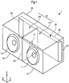
- Fig. 1 is a perspective view to explain a speaker structure according to a first embodiment of the present invention.
- Fig. 2A is a front view of the speaker structure according to the first embodiment.
- Fig. 2B is a plan view of the speaker structure according to the first embodiment.
- Fig. 2C is a right side view of the speaker structure according to the first embodiment.
- Fig. 3A is a cross-sectional view of the speaker structure according to the first embodiment that is cut at line I-I of Fig. 2A .
- Fig. 3B is a cross-sectional view of the speaker structure according to the first embodiment that is cut at line II-II of Fig. 2B , and Fig.
- FIG. 3C is a cross-sectional view of the speaker structure according to the first embodiment that is cut at line III-III of Fig. 2B .
- Fig. 4A is a perspective view showing a partition plate according to the first embodiment.
- Fig. 4B is a right side view of the partition plate according to the first embodiment.
- Fig. 1 for the convenience of explanation, only the port and the partition plate that are located inside are shown by broken lines, whereas other internal components are omitted.
- explanation is to be made defining a width direction (lateral direction) of a housing as X-direction, a front-rear direction (depth direction) thereof as Y-direction, and a thickness direction (height direction) as Z-direction.
- a speaker structure 1 includes a housing 10, a right channel speaker 11, and a left channel speaker 12.
- the speaker structure 1 includes, inside the housing 10, a port 20 and a partition plate 13.
- the port 20 is located, inside the housing 10, on an opposite side of where the right channel speaker 11 and the left channel speaker 12 are disposed, that is, on a rear face side.
- a first opening portion 21 of the port 20 is open to outside in a side face of the housing 10. This ensures that the first opening portion 21 is formed at a position that is difficult to be viewed by users. This permits an increased degree of freedom in designing the speaker structure 1.
- the placement of the port 20 is not limited to the rear face side of an interior of the housing 10.
- the port 20 may be disposed on a top face side or a bottom face side of the interior of the housing 10.
- a space to a side of the speaker 11 and the speaker 12 from the port 20 forms an acoustic space 14.
- the acoustic space 14 is divided by the partition plate 13 into a first space 141 on the speaker 11 side and a second space 142 on the speaker 12 side.
- the first space 141 is a first enclosure 15 in which the speaker 11 is installed.
- the second space 142 is a second enclosure 16 in which the speaker 12 is installed. That is, the partition plate 13 is provided between the first enclosure 15 and the second enclosure 16.
- the partition plate 13 has a communication hole 17.
- the communication hole 17 allows the first enclosure 15 and the second enclosure 16 to communicate with each other.
- the partition plate 13 separates middle and high frequency components out of sounds emitted from rear faces of the speaker 11 and the speaker 12.
- the middle and high frequency components out of the sounds emitted from the rear faces of the speaker 11 and the speaker 12 have smaller pressure changes inside the first enclosure 15 and the second enclosure 16 as compared to the low frequency components. For this reason, the middle and high frequency components are separated between the first space 141 and the second space 142, and this results in an increased separation feeling between the right and left sounds.
- the speaker 11 and the speaker 12 emit sounds containing the middle and high frequency components that depend on respective channels. This makes it possible for the speaker structure 1 to provide users with a feeling of presence.
- the low frequency components out of the sounds emitted from the rear faces of the speaker 11 and the speaker 12 have larger pressure changes inside the first enclosure 15 and the second enclosure 16 as compared to the middle and high frequency components. This allows the oscillation of the low frequency components to propagate between the first space 141 and the second space 142 each other through the communication hole 17. In other words, the communication hole 17 functions as a lowpass filter. Therefore, for the low frequency components out of the sounds emitted from the rear faces of the speaker 11 and the speaker 12, the whole acoustic space 14 functions as one enclosed space.
- the acoustic space 14 has a larger volume as compared with the first enclosure 15 or the second enclosure 16. Thus, it is less likely that the acoustic space 14 interferes with the oscillation of the low frequency components.
- the low frequency components have low directivity. For this reason, in the case of the low frequency components out of the sounds emitted from the rear faces of the speaker 11 and the speaker 12, the separation feeling between the right and left is not a matter of importance; instead, the voluminousness of the bass can be increased.
- the communication hole 17 is formed in a middle of the partition plate 13, as shown in Fig. 4A and Fig. 4B .
- This permits the oscillation of the low frequency components to easily propagate between the first space 141 and the second space 142 each other through the communication hole 17.
- the communication hole 17 is formed at a position too far to one side in the partition plate 13, there arises a bias in distance between the communication hole 17 and an inner wall of the first enclosure 15 or the second enclosure 16. Therefore, in the acoustic space 14, there arises a bias in the propagation of the oscillation of the low frequency components.
- by changing the position of the communication hole 17 in the partition plate 17, it is possible to reproduce a sound depending on users preferences, or kinds of sound to reproduce and so forth.
- the oscillations of the frequency components of not only the low frequency components but also the middle frequency components can easily propagate between the first space 141 and the second space 142 each other. This can help increase the voluminousness of the middle frequency components.
- the first enclosure 15, the second enclosure 16 and the partition plate 13 have a part formed integrally.
- the housing 10 consists of an upper cover 101 and a lower cabinet 102.
- the communication hole 17 may be a gap formed by the upper cover 101 and the lower cabinet 102 in between thereof.
- the port 20 has the first opening portion 21 that is open to outside, and a second opening portion 22 that is disposed on the second enclosure 16.
- the second opening portion 22 corresponds to an "opening portion" of the present invention.
- the port 20 corresponds to a "bass reflex port”.
- the port 20 is communicatively connected to the acoustic space 14 through the second opening portion 22, and communicatively connected to outside through the first opening portion 21.
- the second opening portion 22 of the port 20 may be disposed on either the first enclosure 15 or the second enclosure 16.
- the second opening portion 22 is provided, in the second enclosure 16, on an opposite side of where the speaker 12 is disposed, that is to say, on a rear face side of the second enclosure 16.
- the resonance of sound in the port 20 depends on a shape of an internal space 23 of the port 20.
- the resonance frequency f of the port 20 depends on a cross-sectional area of the port 20, or a length of the port 20.
- the port 20 is one. As in this embodiment, forming one port over the first enclosure 15 and the second enclosure 16 makes it possible to design the port 20 to have a length that spans the width of the housing 10. Therefore, even in a relatively small-sized speaker structure 1, because the cross-sectional area of the port 20 can be designed large, it is possible to suppress the occurrence of wind noise.
- the port 20 is formed in such a manner as to be located on the rear face of the first enclosure 15 and the second enclosure 16. That is, an axis of the port 20 extends along a direction (X-direction) in which the first enclosure 15 and the second enclosure 16 are arranged in a row. This allows the port 20 to be formed with a large length, which in turn makes it possible to keep the resonance frequency f low and thus to sufficiently enhance the low frequency components.
- Fig. 5A and Fig. 5B are cross-sectional views showing modification examples of the partition plate according to the first embodiment. The modification examples of the partition plate according to the first embodiment are explained below.
- the partition plate 13 consists of an upper partition plate 41 and a lower partition plate 42.
- the communication hole 17 is formed by the upper partition plate 41 and the lower partition plate 42.
- the lower partition plate 42 is provided with a wall 40 that faces the communication hole 17.
- the wall 40 protrudes on a side of the first enclosure 15 so as to face the communication hole 17.
- the partition plate 13 With the partition plate 13 provided with the wall 40, it becomes hard for the middle and high frequency components to diffract the communication hole 17.
- the low frequency components out of the sounds emitted from the rear faces of the speaker 11 and the speaker 12 because of their large pressure changes as well as low directivity, pass through the communication hole 17 diffracting the obstacle.
- the partition plate 13 consists of an upper partition plate 41 and a lower partition plate 42.
- the communication hole 17 is formed by the upper partition plate 41 and the lower partition plate 42.
- a wall 45 is formed on the housing 10.
- the wall 45 faces the communication hole 17.
- the wall 45 only needs to face the communication hole 17; and thus, for example, the wall 45 may be any one as long as it is formed in a rectangular parallelepiped shape.
- the wall 45 and the partition plate 42 may be formed integrally together with the housing 10. In this case, because of such a simplified structure of the wall 45, production thereof becomes easy.
- the wall 45 is installed in such a manner as to protrude from the partition plate 13 toward the first enclosure 15 so as to face the communication hole 17. Therefore, in the same manner as in the modification example shown in Fig. 5A , it become hard for the middle and high frequency components, which have small pressure changes as well as high directivity, to diffract the communication hole 17. This permits the middle and high frequency components to be separated more easily between the first space 141 and the second space 142 from each other. And this results in an improved separation feeling between the right and left sounds.
- the wall 40 and the wall 45 may protrude on the side of at least either the first enclosure 15 or the second enclosure 16. No matter which direction the wall 40 and the wall 45 may be installed in such a manner as to protrude toward, the same effect is obtained.
- the quality of sound to reproduce changes.
- a length d1 shown in Fig. 5A is long, as compared with a case where the length of d1 is short, it becomes easier for the oscillation of the low frequency components to propagate between the first space 141 and the second space 142 each other.
- the d1 shows a distance from the communication hole 17 to a wall face of the wall 40 on a side of the communication hole 17. This helps increase the voluminousness of the low frequency components.
- Fig. 6A is a perspective view showing a partition plate according to a second embodiment of the present invention.
- Fig. 6B, Fig. 6C and Fig. 6D are cross-sectional views of the partition plate according to the second embodiment. Subsequently, the modification examples of the partition plate according to the second embodiment are explained. In the second embodiment, descriptions of configurations similar to those of the partition plate according to the first embodiment will be omitted.
- the partition plate 13 is composed of a single member.
- the partition plate 13 is formed as part of the upper cover 101 or the lower cabinet 102.
- a communication hole 17 that allows the first space 141 and the second space 142 to communicate with each other is formed.
- the partition plate 13 is provided with a wall 55 that faces the communication hole 17.
- the wall 55 is formed in such a manner as to protrude from the partition plate 13 toward the first enclosure 15 so as to face the communication hole 17.
- the oscillation of the low frequency components propagates between the first space 141 and the second space 142 each other through a communication hole 50 that is formed along X-Z plane by the communication hole 17 and the wall 55.
- the partition plate 13 provided with the wall 55, it becomes hard for the oscillation of the middle and high frequency components to propagate between the first space 141 and the second space 142 each other.
- the wall 55 is formed integrally with the partition plate 13. By changing the structure of the partition plate wall 55, it is possible to adjust the quality of sound to reproduce from the speaker structure 1.
- a sound absorbing material 56 may be provided between the partition plate 13 and the wall 55. With the sound absorbing material 56, because it further interferes with diffraction of the middle and high frequency components through the communication hole 17, it becomes more difficult for the oscillation of the middle and high frequency components to propagate between the first space 141 and the second space 142 each other. This results in an improved separation feeling between the reproduced sounds.
- the partition plate 13 may be provided with a wall 57.
- the wall 57 has a face 58 that is crooked and faces the communication hole 17. With the face 58 having a protruding obstacle, it becomes more difficult for the oscillation of the middle and high frequency components that have high directivity to propagate between the first space 141 and the second space 142 each other. Thus, the separation feeling between the reproduced sounds is improved.
- Fig. 7A, Fig. 7B, Fig. 7C and Fig. 7D are views showing modification examples of the communication hole 17.
- a shape of a communication hole 61 may be formed in a circle.
- the partition plate 13 is formed in a disk shape.
- the communication hole 61 can be disposed in a middle of the partition plate 13.
- a shape of a communication hole 62 may be formed in a polygon. Further, the communication hole 62 may be formed more than one. By forming the communication hole 62 more than one and devising how to arrange the respective communication hole 62, so that it is possible to correspond to the usage mode of various users.
- a bridging portion 63 is formed in between the communication holes 62.
- the oscillation of the middle and high frequency components having small pressure changes and high directivity are easily affected by the bridging portion 63, to propagate between the first space 141 and the second space 142 each other.
- the separation feeling between the reproduced sounds is improved by the partition plate 13.
- the communication hole 17 may be disposed either on a front face side of the speaker structure as shown in Fig. 7C , or on the rear face side of the speaker structure as shown in Fig. 7D .
- the communication hole 17 becomes close to the speaker 11 and the speaker 12.
- the sounds emitted from the speaker 11 and the speaker 12 reach the communication hole 17 directly without being attenuated. This permits the oscillation of the low frequency components to easily propagate between the first space 141 and the second space 142 each other. And this helps increase the voluminousness of the low frequency components.
- the communication hole 17 becomes far from the speaker 11 and the speaker 12.
- the sounds emitted from the speaker 11 and the speaker 12 reach the communication hole 17 in an attenuated manner. Therefore, the oscillation of the low frequency components is caused to propagate between the first space 141 and the second space 142 each other in a state of being attenuated. This can help reduce the voluminousness of the low frequency components.
- the voluminousness of the low frequency components can be adjusted by the position of the communication hole 17.
- Fig. 8A is a perspective view showing a speaker structure according to a third embodiment of the present invention.
- Fig. 8B is a cross-sectional view of the speaker structure according to the third embodiment.
- descriptions of configurations similar to those of the speaker structure according to the speaker structure 1 of the first embodiment will be omitted.
- a speaker structure 71 has a port 120.
- the port 120 has a different shape from the port 20 of the speaker structure 1.
- the port 120 has a shape bent in L-shape.
- An opening portion 22 of the port 120 is provided in a side face of the second enclosure 16 on an opposite side of the partition plate 13. Therefore, with the port 120, a distance between the first opening portion 21 and the second opening portion 22 becomes longer. This allows the port 120 to have a larger length, which in turn makes it possible to keep the resonance frequency f lower and thus to sufficiently reproduce the low frequency components.
- Fig. 9A is a perspective view showing a speaker structure according to a fourth embodiment of the present invention.
- Fig. 9B is a cross-sectional view of the speaker structure according to the fourth embodiment.
- descriptions of configurations similar to those of the speaker structure according to the speaker structure 1 of the first embodiment will be omitted.
- a speaker structure 81 has a port 220.
- the port 220 has a different shape from the port 20 of the speaker structure 1.
- the port 220 has, near a middle thereof in X direction, a protrusion portion 221 that is bent in such a manner as to protrude toward a side of the speaker 11 and the speaker 12.
- Part of the port 220 is bent in such a manner as to protrude from a rear face side to a front face side of the speaker structure 81, that is, along a direction of Y-axis. Therefore, it is possible to form the port 220 longer as compared with linearly formed ports. This in turn makes it possible to keep the resonance frequency f lower and thus to sufficiently reproduce the low frequency components.
- the protrusion portion 22 together with a partition plate 113, separates the acoustic space 14 into a first space 141 and a second space 142.
- the partition plate 113 can be formed smaller.
- the partition plate 13 is formed integrally with the housing 10 in the embodiments, it is not necessarily so.
- the partition plate 13 may be formed detachably as a member that is separate from the upper cover 101 and the lower cabinet 102. In this case, by changing the partition plate 13, users can easily adjust the quality of sound to reproduce from the speaker structure 1.
- the position, the size or the like of the second opening portion 22 of the port is not limited to those illustrated in the embodiments, but can be modified.
- the position of the second opening portion 22 may be moved in the front-rear direction, that is, along Y direction. This allows adjustments of the quality of sound to reproduce from the speaker structure 1.
- the first opening portion 21 of the port 20 is open to outside in a side face of the housing 10, it may not be limited as such, but be open to outside in a rear face of the housing 10, for example.
- the sound emitted out of the port 20 is low frequency components having low directivity. Therefore, no matter which direction the sound emission occurs from, there is no problem.
- the first opening portion 21 is formed at a position that is difficult to be viewed by users, a degree of freedom in designing the speaker structure 1 increases.
- the present invention is not limited to passive speakers, but is also applicable to, for example, an active speaker with built-in amplifier.
- the present invention may be applied to an integrated speaker with a communication function such as Bluetooth (Registered Trademark), Wi-Fi (Registered Trademark) .
- the present invention may be applied to an speaker with a digital sound signal reproduction function.
- the present invention may be applied to an speaker with a sound signal amplification or adjustment function or the like.
Landscapes
- Physics & Mathematics (AREA)
- Engineering & Computer Science (AREA)
- Acoustics & Sound (AREA)
- Signal Processing (AREA)
- Health & Medical Sciences (AREA)
- Otolaryngology (AREA)
- Details Of Audible-Bandwidth Transducers (AREA)
- Obtaining Desirable Characteristics In Audible-Bandwidth Transducers (AREA)
- Stereophonic Arrangements (AREA)
Abstract
Description
- A preferred embodiment of the present invention relates to a small-sized stereophonic speaker structure.
- Patent Literature 1 (Publication of Japanese Utility Model Application, Publication Number:
JPH01105296 (U - The stereophonic speaker apparatus described in Patent Literature 1 is provided with an acoustic space portion between right and left enclosures. The stereophonic speaker apparatus described in Patent Literature 1 enhances low frequency components that are emitted from rear faces of the right channel speaker and the left channel speaker in the acoustic space portion, and thereby realizes a powerful stereophonic reproduction.
- In the stereophonic speaker apparatus described in Patent Literature 1, the acoustic space portion to enhance the low frequency components is formed between the right and the left enclosures. For this reason, the speaker apparatus needs to have a wider width by a width of the acoustic space portion. Thus, in designing a small-sized speaker apparatus, the size of the acoustic space portion is subject to restriction.
- In view of the foregoing, a preferred embodiment of the present invention is directed to provide a small-sized speaker structure capable of sufficiently reproducing low frequency components while separating high frequency components.
- A speaker structure according to a preferred embodiment of the present invention includes a first enclosure, a second enclosure, a partition plate and a bass reflex port. The partition plate has a communication hole that is provided between the first enclosure and the second enclosure and allows the first enclosure and the second enclosure to communicate with each other. The bass reflex port is disposed at least on either the first enclosure or the second enclosure.
- According to the present invention, in one aspect thereof, it is made possible to sufficiently reproduce low frequency components while separating high frequency components, without increasing a width of a housing.
- The above and other elements, features, characteristics, and advantages of the present invention will become more apparent from the following detailed description of the preferred embodiments with reference to the attached drawings.
-
-
Fig. 1 is a perspective view to explain a speaker structure according to a first embodiment of the present invention. -
Fig. 2A is a front view of the speaker structure according to the first embodiment. -
Fig. 2B is a plan view of the speaker structure according to the first embodiment. -
Fig. 2C is a right side view of the speaker structure according to the first embodiment. -
Fig. 3A is a cross-sectional view of the speaker structure according to the first embodiment. -
Fig. 3B is a cross-sectional view of the speaker structure according to the first embodiment. -
Fig. 3C is a cross-sectional view of the speaker structure according to the first embodiment. -
Fig. 4A is a perspective view showing a partition plate according to the first embodiment. -
Fig. 4B is a right side view of the partition plate according to the first embodiment. -
Fig. 5A is a cross-sectional view showing a modification example of the partition plate according to the first embodiment. -
Fig. 5B is a cross-sectional view showing another modification example of the partition plate according to the first embodiment. -
Fig. 6A is a perspective view showing a partition plate according to a second embodiment of the present invention. -
Fig. 6B is a cross-sectional view of the partition plate according to the second embodiment. -
Fig. 6C is another cross-sectional view of the partition plate according to the second embodiment. -
Fig. 6D is still another cross-sectional view of the partition plate according to the second embodiment. -
Fig. 7A is a view showing a modification example of the communication hole. -
Fig. 7B is a view showing another modification example of the communication hole. -
Fig. 7C is a view showing still another modification example of the communication hole. -
Fig. 7D is a view showing yet still another modification example of the communication hole. -
Fig. 8A is a perspective view showing a speaker structure according to a third embodiment of the present invention. -
Fig. 8B is a cross-sectional view of the speaker structure according to the third embodiment. -
Fig. 9A is a perspective view showing a speaker structure according to a fourth embodiment of the present invention. -
Fig. 9B is a cross-sectional view of the speaker structure according to the fourth embodiment. -
Fig. 1 is a perspective view to explain a speaker structure according to a first embodiment of the present invention.Fig. 2A is a front view of the speaker structure according to the first embodiment.Fig. 2B is a plan view of the speaker structure according to the first embodiment.Fig. 2C is a right side view of the speaker structure according to the first embodiment.Fig. 3A is a cross-sectional view of the speaker structure according to the first embodiment that is cut at line I-I ofFig. 2A .Fig. 3B is a cross-sectional view of the speaker structure according to the first embodiment that is cut at line II-II ofFig. 2B , andFig. 3C is a cross-sectional view of the speaker structure according to the first embodiment that is cut at line III-III ofFig. 2B .Fig. 4A is a perspective view showing a partition plate according to the first embodiment.Fig. 4B is a right side view of the partition plate according to the first embodiment. Additionally, inFig. 1 , for the convenience of explanation, only the port and the partition plate that are located inside are shown by broken lines, whereas other internal components are omitted. Also, hereinafter, explanation is to be made defining a width direction (lateral direction) of a housing as X-direction, a front-rear direction (depth direction) thereof as Y-direction, and a thickness direction (height direction) as Z-direction. - As shown in
Fig. 1 ,Fig. 2A, Fig. 2B and Fig. 2C , a speaker structure 1 includes ahousing 10, aright channel speaker 11, and aleft channel speaker 12. The speaker structure 1 includes, inside thehousing 10, aport 20 and apartition plate 13. Theport 20 is located, inside thehousing 10, on an opposite side of where theright channel speaker 11 and theleft channel speaker 12 are disposed, that is, on a rear face side. Afirst opening portion 21 of theport 20 is open to outside in a side face of thehousing 10. This ensures that thefirst opening portion 21 is formed at a position that is difficult to be viewed by users. This permits an increased degree of freedom in designing the speaker structure 1. Also, the placement of theport 20 is not limited to the rear face side of an interior of thehousing 10. For example, theport 20 may be disposed on a top face side or a bottom face side of the interior of thehousing 10. - In the speaker structure 1, a space to a side of the
speaker 11 and thespeaker 12 from theport 20 forms anacoustic space 14. Theacoustic space 14 is divided by thepartition plate 13 into afirst space 141 on thespeaker 11 side and asecond space 142 on thespeaker 12 side. Thefirst space 141 is afirst enclosure 15 in which thespeaker 11 is installed. Thesecond space 142 is asecond enclosure 16 in which thespeaker 12 is installed. That is, thepartition plate 13 is provided between thefirst enclosure 15 and thesecond enclosure 16. - As shown in
Fig. 3A, Fig. 3B, Fig. 3C ,Fig. 4A and Fig. 4B , thepartition plate 13 has acommunication hole 17. Thecommunication hole 17 allows thefirst enclosure 15 and thesecond enclosure 16 to communicate with each other. - The
partition plate 13 separates middle and high frequency components out of sounds emitted from rear faces of thespeaker 11 and thespeaker 12. The middle and high frequency components out of the sounds emitted from the rear faces of thespeaker 11 and thespeaker 12 have smaller pressure changes inside thefirst enclosure 15 and thesecond enclosure 16 as compared to the low frequency components. For this reason, the middle and high frequency components are separated between thefirst space 141 and thesecond space 142, and this results in an increased separation feeling between the right and left sounds. Thespeaker 11 and thespeaker 12 emit sounds containing the middle and high frequency components that depend on respective channels. This makes it possible for the speaker structure 1 to provide users with a feeling of presence. - The low frequency components out of the sounds emitted from the rear faces of the
speaker 11 and thespeaker 12 have larger pressure changes inside thefirst enclosure 15 and thesecond enclosure 16 as compared to the middle and high frequency components. This allows the oscillation of the low frequency components to propagate between thefirst space 141 and thesecond space 142 each other through thecommunication hole 17. In other words, thecommunication hole 17 functions as a lowpass filter. Therefore, for the low frequency components out of the sounds emitted from the rear faces of thespeaker 11 and thespeaker 12, the wholeacoustic space 14 functions as one enclosed space. Theacoustic space 14 has a larger volume as compared with thefirst enclosure 15 or thesecond enclosure 16. Thus, it is less likely that theacoustic space 14 interferes with the oscillation of the low frequency components. Besides, the low frequency components have low directivity. For this reason, in the case of the low frequency components out of the sounds emitted from the rear faces of thespeaker 11 and thespeaker 12, the separation feeling between the right and left is not a matter of importance; instead, the voluminousness of the bass can be increased. - It is preferable that the
communication hole 17 is formed in a middle of thepartition plate 13, as shown inFig. 4A and Fig. 4B . This permits the oscillation of the low frequency components to easily propagate between thefirst space 141 and thesecond space 142 each other through thecommunication hole 17. In contrast, if thecommunication hole 17 is formed at a position too far to one side in thepartition plate 13, there arises a bias in distance between thecommunication hole 17 and an inner wall of thefirst enclosure 15 or thesecond enclosure 16. Therefore, in theacoustic space 14, there arises a bias in the propagation of the oscillation of the low frequency components. On the other hand, by changing the position of thecommunication hole 17 in thepartition plate 17, it is possible to reproduce a sound depending on users preferences, or kinds of sound to reproduce and so forth. - It is also possible to change the quality of sound to reproduce by a size of the
communication hole 17. For example, when a cross-section of thecommunication hole 17 is large, the oscillations of the frequency components of not only the low frequency components but also the middle frequency components can easily propagate between thefirst space 141 and thesecond space 142 each other. This can help increase the voluminousness of the middle frequency components. - In the speaker structure 1, the
first enclosure 15, thesecond enclosure 16 and thepartition plate 13 have a part formed integrally. For example, as shown inFig. 3B and Fig. 3C , thehousing 10 consists of anupper cover 101 and alower cabinet 102. Thecommunication hole 17 may be a gap formed by theupper cover 101 and thelower cabinet 102 in between thereof. In this manner, since thefirst enclosure 15, thesecond enclosure 16 and thepartition plate 13 are composed of two members for thefirst enclosure 15, thesecond enclosure 16 and thepartition plate 17, their production process is simplified. - The
port 20 has thefirst opening portion 21 that is open to outside, and asecond opening portion 22 that is disposed on thesecond enclosure 16. Thesecond opening portion 22 corresponds to an "opening portion" of the present invention. Also, theport 20 corresponds to a "bass reflex port". - The
port 20 is communicatively connected to theacoustic space 14 through thesecond opening portion 22, and communicatively connected to outside through thefirst opening portion 21. Thesecond opening portion 22 of theport 20 may be disposed on either thefirst enclosure 15 or thesecond enclosure 16. Thesecond opening portion 22 is provided, in thesecond enclosure 16, on an opposite side of where thespeaker 12 is disposed, that is to say, on a rear face side of thesecond enclosure 16. - The resonance of sound in the
port 20 depends on a shape of aninternal space 23 of theport 20. The resonance frequency f of theport 20 depends on a cross-sectional area of theport 20, or a length of theport 20. - It is preferable that the
port 20 is one. As in this embodiment, forming one port over thefirst enclosure 15 and thesecond enclosure 16 makes it possible to design theport 20 to have a length that spans the width of thehousing 10. Therefore, even in a relatively small-sized speaker structure 1, because the cross-sectional area of theport 20 can be designed large, it is possible to suppress the occurrence of wind noise. - As shown in
Fig. 3A , theport 20 is formed in such a manner as to be located on the rear face of thefirst enclosure 15 and thesecond enclosure 16. That is, an axis of theport 20 extends along a direction (X-direction) in which thefirst enclosure 15 and thesecond enclosure 16 are arranged in a row. This allows theport 20 to be formed with a large length, which in turn makes it possible to keep the resonance frequency f low and thus to sufficiently enhance the low frequency components. -
Fig. 5A and Fig. 5B are cross-sectional views showing modification examples of the partition plate according to the first embodiment. The modification examples of the partition plate according to the first embodiment are explained below. - As shown in
Fig. 5A , thepartition plate 13 consists of anupper partition plate 41 and alower partition plate 42. Thecommunication hole 17 is formed by theupper partition plate 41 and thelower partition plate 42. Thelower partition plate 42 is provided with awall 40 that faces thecommunication hole 17. Thewall 40 protrudes on a side of thefirst enclosure 15 so as to face thecommunication hole 17. - With the
partition plate 13 provided with thewall 40, it becomes hard for the middle and high frequency components to diffract thecommunication hole 17. The middle and high frequency components out of the sounds emitted from the rear faces of thespeaker 11 and thespeaker 12, because of their small pressure changes as well as high directivity, become hard to diffract thecommunication hole 17 that is provided with an obstacle. In contrast, the low frequency components out of the sounds emitted from the rear faces of thespeaker 11 and thespeaker 12, because of their large pressure changes as well as low directivity, pass through thecommunication hole 17 diffracting the obstacle. This permits the middle and high frequency components to be separated more easily between thefirst space 141 and thesecond space 142 from each other. And this results in an improved separation feeling between the right and left sounds. - In another modification example shown in
Fig. 5B , thepartition plate 13 consists of anupper partition plate 41 and alower partition plate 42. Thecommunication hole 17 is formed by theupper partition plate 41 and thelower partition plate 42. Also, awall 45 is formed on thehousing 10. Thewall 45 faces thecommunication hole 17. In this configuration, thewall 45 only needs to face thecommunication hole 17; and thus, for example, thewall 45 may be any one as long as it is formed in a rectangular parallelepiped shape. Further, thewall 45 and thepartition plate 42 may be formed integrally together with thehousing 10. In this case, because of such a simplified structure of thewall 45, production thereof becomes easy. - The
wall 45 is installed in such a manner as to protrude from thepartition plate 13 toward thefirst enclosure 15 so as to face thecommunication hole 17. Therefore, in the same manner as in the modification example shown inFig. 5A , it become hard for the middle and high frequency components, which have small pressure changes as well as high directivity, to diffract thecommunication hole 17. This permits the middle and high frequency components to be separated more easily between thefirst space 141 and thesecond space 142 from each other. And this results in an improved separation feeling between the right and left sounds. - Additionally, in the modification examples shown in
Fig. 5A and Fig. 5B , thewall 40 and thewall 45 may protrude on the side of at least either thefirst enclosure 15 or thesecond enclosure 16. No matter which direction thewall 40 and thewall 45 may be installed in such a manner as to protrude toward, the same effect is obtained. - If the position of the
wall 40 or thewall 45 changes, the quality of sound to reproduce changes. For example, when a length d1 shown inFig. 5A is long, as compared with a case where the length of d1 is short, it becomes easier for the oscillation of the low frequency components to propagate between thefirst space 141 and thesecond space 142 each other. The d1 shows a distance from thecommunication hole 17 to a wall face of thewall 40 on a side of thecommunication hole 17. This helps increase the voluminousness of the low frequency components. - On the other hand, when the length dl is short, it becomes harder for the oscillation of the middle and high frequency components to propagate between the
first space 141 and thesecond space 142 each other. This results in an improved separation feeling between reproduced sounds. -
Fig. 6A is a perspective view showing a partition plate according to a second embodiment of the present invention.Fig. 6B, Fig. 6C and Fig. 6D are cross-sectional views of the partition plate according to the second embodiment. Subsequently, the modification examples of the partition plate according to the second embodiment are explained. In the second embodiment, descriptions of configurations similar to those of the partition plate according to the first embodiment will be omitted. - As shown in
Fig. 6A and Fig. 6B , thepartition plate 13 is composed of a single member. Thepartition plate 13 is formed as part of theupper cover 101 or thelower cabinet 102. In thepartition plate 13, acommunication hole 17 that allows thefirst space 141 and thesecond space 142 to communicate with each other is formed. Thepartition plate 13 is provided with awall 55 that faces thecommunication hole 17. Thewall 55 is formed in such a manner as to protrude from thepartition plate 13 toward thefirst enclosure 15 so as to face thecommunication hole 17. - The oscillation of the low frequency components propagates between the
first space 141 and thesecond space 142 each other through acommunication hole 50 that is formed along X-Z plane by thecommunication hole 17 and thewall 55. With thepartition plate 13 provided with thewall 55, it becomes hard for the oscillation of the middle and high frequency components to propagate between thefirst space 141 and thesecond space 142 each other. - Further, the
wall 55 is formed integrally with thepartition plate 13. By changing the structure of thepartition plate wall 55, it is possible to adjust the quality of sound to reproduce from the speaker structure 1. - Also, as shown in
Fig. 6C , asound absorbing material 56 may be provided between thepartition plate 13 and thewall 55. With thesound absorbing material 56, because it further interferes with diffraction of the middle and high frequency components through thecommunication hole 17, it becomes more difficult for the oscillation of the middle and high frequency components to propagate between thefirst space 141 and thesecond space 142 each other. This results in an improved separation feeling between the reproduced sounds. - Moreover, as shown in
Fig. 6D , thepartition plate 13 may be provided with awall 57. Thewall 57 has aface 58 that is crooked and faces thecommunication hole 17. With theface 58 having a protruding obstacle, it becomes more difficult for the oscillation of the middle and high frequency components that have high directivity to propagate between thefirst space 141 and thesecond space 142 each other. Thus, the separation feeling between the reproduced sounds is improved. -
Fig. 7A, Fig. 7B, Fig. 7C and Fig. 7D are views showing modification examples of thecommunication hole 17. - As shown in
Fig. 7A , a shape of acommunication hole 61 may be formed in a circle. For example, when the housing has a cylindrical shape, thepartition plate 13 is formed in a disk shape. In this case, thecommunication hole 61 can be disposed in a middle of thepartition plate 13. - As shown in
Fig. 7B , a shape of acommunication hole 62 may be formed in a polygon. Further, thecommunication hole 62 may be formed more than one. By forming thecommunication hole 62 more than one and devising how to arrange therespective communication hole 62, so that it is possible to correspond to the usage mode of various users. - For example, as shown in
Fig. 7B , in a case where a plurality of the communication holes 62 in a hexagonal shape are arranged close to each other, a bridgingportion 63 is formed in between the communication holes 62. In this case, it becomes difficult for the oscillation of the middle and high frequency components having small pressure changes and high directivity are easily affected by the bridgingportion 63, to propagate between thefirst space 141 and thesecond space 142 each other. Thus, the separation feeling between the reproduced sounds is improved by thepartition plate 13. - The
communication hole 17 may be disposed either on a front face side of the speaker structure as shown inFig. 7C , or on the rear face side of the speaker structure as shown inFig. 7D . In the case where thecommunication hole 17 is disposed on the front face side of the speaker structure 1, thecommunication hole 17 becomes close to thespeaker 11 and thespeaker 12. The sounds emitted from thespeaker 11 and thespeaker 12 reach thecommunication hole 17 directly without being attenuated. This permits the oscillation of the low frequency components to easily propagate between thefirst space 141 and thesecond space 142 each other. And this helps increase the voluminousness of the low frequency components. - In the case where the
communication hole 17 is disposed on the rear face side of the speaker structure 1, thecommunication hole 17 becomes far from thespeaker 11 and thespeaker 12. The sounds emitted from thespeaker 11 and thespeaker 12 reach thecommunication hole 17 in an attenuated manner. Therefore, the oscillation of the low frequency components is caused to propagate between thefirst space 141 and thesecond space 142 each other in a state of being attenuated. This can help reduce the voluminousness of the low frequency components. Thus, the voluminousness of the low frequency components can be adjusted by the position of thecommunication hole 17. -
Fig. 8A is a perspective view showing a speaker structure according to a third embodiment of the present invention.Fig. 8B is a cross-sectional view of the speaker structure according to the third embodiment. In the third embodiment, descriptions of configurations similar to those of the speaker structure according to the speaker structure 1 of the first embodiment will be omitted. - As shown in
Fig. 8A and Fig. 8B , aspeaker structure 71 according to the third embodiment has aport 120. Theport 120 has a different shape from theport 20 of the speaker structure 1. Theport 120 has a shape bent in L-shape. - An opening
portion 22 of theport 120 is provided in a side face of thesecond enclosure 16 on an opposite side of thepartition plate 13. Therefore, with theport 120, a distance between thefirst opening portion 21 and thesecond opening portion 22 becomes longer. This allows theport 120 to have a larger length, which in turn makes it possible to keep the resonance frequency f lower and thus to sufficiently reproduce the low frequency components. -
Fig. 9A is a perspective view showing a speaker structure according to a fourth embodiment of the present invention.Fig. 9B is a cross-sectional view of the speaker structure according to the fourth embodiment. In the fourth embodiment, descriptions of configurations similar to those of the speaker structure according to the speaker structure 1 of the first embodiment will be omitted. - As shown in
Fig. 9A and Fig. 9B , aspeaker structure 81 according to the fourth embodiment has aport 220. Theport 220 has a different shape from theport 20 of the speaker structure 1. Theport 220 has, near a middle thereof in X direction, aprotrusion portion 221 that is bent in such a manner as to protrude toward a side of thespeaker 11 and thespeaker 12. - Part of the
port 220 is bent in such a manner as to protrude from a rear face side to a front face side of thespeaker structure 81, that is, along a direction of Y-axis. Therefore, it is possible to form theport 220 longer as compared with linearly formed ports. This in turn makes it possible to keep the resonance frequency f lower and thus to sufficiently reproduce the low frequency components. - Besides, the
protrusion portion 221, together with apartition plate 113, separates theacoustic space 14 into afirst space 141 and asecond space 142. As a result, thepartition plate 113 can be formed smaller. - Further, although the
partition plate 13 is formed integrally with thehousing 10 in the embodiments, it is not necessarily so. For example, thepartition plate 13 may be formed detachably as a member that is separate from theupper cover 101 and thelower cabinet 102. In this case, by changing thepartition plate 13, users can easily adjust the quality of sound to reproduce from the speaker structure 1. - Also, the position, the size or the like of the
second opening portion 22 of the port is not limited to those illustrated in the embodiments, but can be modified. For example, the position of thesecond opening portion 22 may be moved in the front-rear direction, that is, along Y direction. This allows adjustments of the quality of sound to reproduce from the speaker structure 1. - Moreover, although the
first opening portion 21 of theport 20 is open to outside in a side face of thehousing 10, it may not be limited as such, but be open to outside in a rear face of thehousing 10, for example. The sound emitted out of theport 20 is low frequency components having low directivity. Therefore, no matter which direction the sound emission occurs from, there is no problem. Besides, since thefirst opening portion 21 is formed at a position that is difficult to be viewed by users, a degree of freedom in designing the speaker structure 1 increases. - Still, although a passive speaker is illustrated in the embodiments, the present invention is not limited to passive speakers, but is also applicable to, for example, an active speaker with built-in amplifier. Also, the present invention may be applied to an integrated speaker with a communication function such as Bluetooth (Registered Trademark), Wi-Fi (Registered Trademark) . The present invention may be applied to an speaker with a digital sound signal reproduction function. The present invention may be applied to an speaker with a sound signal amplification or adjustment function or the like.
- Lastly, the foregoing preferred embodiments are illustrative in all points and should not be construed to limit the present invention. The scope of the present invention is defined not by the foregoing preferred embodiment but by the following claims. Further, the scope of the present invention is intended to include all modifications within the scopes of the claims and within the meanings and scopes of equivalents.
Claims (16)
- A speaker structure (1) comprising:a first enclosure (15);a second enclosure (16);a partition plate (13) having a communication hole (17) that is provided between the first enclosure (15) and the second enclosure (16) and allows the first enclosure (15) and the second enclosure (16) to communicate with each other; anda bass reflex port (20) disposed at least on either the first enclosure (15) or the second enclosure (16).
- The speaker structure according to claim 1, whereinthe bass reflex port (20) is disposed over the first enclosure (15) and the second enclosure (16).
- The speaker structure according to claim 2, whereinthe bass reflex port (20) is located on a rear face side of the first enclosure (15) and the second enclosure (16).
- The speaker structure according to claim 2 or 3, whereina cross-sectional shape of the bass reflex port (20) is long along a height direction of the first enclosure (15) and the second enclosure (16).
- The speaker structure according to any one of claims 2 to 4 , whereinan axis of the bass reflex port (20) extends along a direction in which the first enclosure (15) and the second enclosure (16) are arranged in a row.
- The speaker structure according to any one of claims 1 to 5, whereinthe bass reflex port (20) has a bent portion halfway in a plan view.
- The speaker structure according to claim 6, whereinthe bass reflex port (20) is disposed along an inner wall face of the first enclosure (15) or the second enclosure (16).
- The speaker structure according to any one of claims 1 to 7, whereinthe bass reflex port (20) is one.
- The speaker structure according to claim 1, comprising:a wall facing the communication hole (17).
- The speaker structure according to claim 9, whereinthe wall protrudes from an inner wall of the first enclosure (15) or the second enclosure (16).
- The speaker structure according to claim 9, whereinthe wall protrudes from the partition plate (13).
- The speaker structure according to claim 11, whereinthe wall protrudes from a plurality of portions of the partition plate (13).
- The speaker structure according to any one of claims 9 to 12, whereina sound absorbing material is disposed between the wall and the communication hole (17).
- The speaker structure according to any one of claims 1 to 13, whereinthe communication hole (17) is formed in a middle of the partition plate (13).
- The speaker structure according to any one of claims 1 to 14, whereinthe first enclosure (15), the second enclosure (16) and the partition plate (13) have a part formed integrally.
- The speaker structure according to any one of claims 1 to 15, comprising:a plurality of the communication holes (17).
Applications Claiming Priority (1)
| Application Number | Priority Date | Filing Date | Title |
|---|---|---|---|
| JP2017247255A JP7069699B2 (en) | 2017-12-25 | 2017-12-25 | Speaker structure |
Publications (2)
| Publication Number | Publication Date |
|---|---|
| EP3503578A1 true EP3503578A1 (en) | 2019-06-26 |
| EP3503578B1 EP3503578B1 (en) | 2022-12-14 |
Family
ID=64746268
Family Applications (1)
| Application Number | Title | Priority Date | Filing Date |
|---|---|---|---|
| EP18214232.3A Active EP3503578B1 (en) | 2017-12-25 | 2018-12-19 | Speaker structure |
Country Status (4)
| Country | Link |
|---|---|
| US (1) | US10477317B2 (en) |
| EP (1) | EP3503578B1 (en) |
| JP (1) | JP7069699B2 (en) |
| CN (1) | CN110022509B (en) |
Families Citing this family (5)
| Publication number | Priority date | Publication date | Assignee | Title |
|---|---|---|---|---|
| JP7565507B2 (en) * | 2019-10-30 | 2024-10-11 | パナソニックIpマネジメント株式会社 | Building Materials |
| JP7197025B2 (en) | 2019-10-31 | 2022-12-27 | ヤマハ株式会社 | Partition system with speakers |
| US11159762B2 (en) | 2019-11-04 | 2021-10-26 | Hisense Visual Technology Co., Ltd. | Display device and speaker assembly |
| CN112788492B (en) * | 2019-11-04 | 2022-02-15 | 海信视像科技股份有限公司 | Display device and speaker assembly |
| JP7648342B2 (en) * | 2020-03-10 | 2025-03-18 | パナソニック インテレクチュアル プロパティ コーポレーション オブ アメリカ | Speaker System |
Citations (3)
| Publication number | Priority date | Publication date | Assignee | Title |
|---|---|---|---|---|
| JPH01105296U (en) | 1987-12-29 | 1989-07-14 | ||
| JPH11178083A (en) * | 1997-12-10 | 1999-07-02 | Sony Corp | Speaker device |
| US8256566B1 (en) * | 2011-08-19 | 2012-09-04 | Rogersound Labs, LLC | Speaker enclosure |
Family Cites Families (24)
| Publication number | Priority date | Publication date | Assignee | Title |
|---|---|---|---|---|
| US4270023A (en) * | 1979-05-31 | 1981-05-26 | Beveridge Harold N | Cylindrical speaker mechanism |
| JPH01105296A (en) * | 1987-06-19 | 1989-04-21 | Toshiba Corp | Display area switching control system for plasma display |
| JPH03267899A (en) * | 1990-03-16 | 1991-11-28 | Nec Home Electron Ltd | Phase inversion type speaker |
| US5197103A (en) * | 1990-10-05 | 1993-03-23 | Kabushiki Kaisha Kenwood | Low sound loudspeaker system |
| US5147986A (en) * | 1990-12-03 | 1992-09-15 | Tandy Corporation | Subwoofer speaker system |
| US5150417A (en) * | 1991-02-25 | 1992-09-22 | Socon Ab | Bass reflex type speaker system |
| US5602367A (en) * | 1994-12-19 | 1997-02-11 | Meyer Sound Laboratories Incorporated | Multiple tuned high power bass reflex speaker system |
| GB2318475B (en) * | 1996-10-21 | 2000-08-23 | B & W Loudspeakers | Enclosures for loudspeaker drive units |
| CN2288564Y (en) * | 1997-03-28 | 1998-08-19 | 沙占起 | Loadspeaker box |
| US5892183A (en) * | 1997-07-26 | 1999-04-06 | U.S. Philips Corporation | Loudspeaker system having a bass-reflex port |
| US5875255A (en) * | 1997-08-28 | 1999-02-23 | Campbell; Paul G. | High power electroacoustic speaker system having wide band frequency response |
| US6389146B1 (en) * | 2000-02-17 | 2002-05-14 | American Technology Corporation | Acoustically asymmetric bandpass loudspeaker with multiple acoustic filters |
| JP3070553U (en) * | 2000-01-27 | 2000-08-04 | 第一フェーズ株式会社 | Speaker device |
| JP2005080173A (en) * | 2003-09-03 | 2005-03-24 | Sony Corp | Electronic device and speaker device |
| JP4306627B2 (en) * | 2005-03-09 | 2009-08-05 | ソニー株式会社 | Bass reflex type speaker device, speaker box and image display device |
| CN2824484Y (en) * | 2005-07-22 | 2006-10-04 | 张壮发 | Loudspeaker system |
| US8284977B2 (en) * | 2008-01-24 | 2012-10-09 | Creative Technology Ltd | Multi chamber ported stereo speaker |
| FR2994519B1 (en) * | 2012-08-07 | 2015-09-25 | Nexo | BASS-REFLEX SPEAKER WITH EVENT |
| US20140193005A1 (en) * | 2013-01-07 | 2014-07-10 | Jason R. RIGGS | Audio Speaker System with Semi-Shared Passive Radiators |
| CN203057452U (en) * | 2013-01-21 | 2013-07-10 | 张日奔 | 1/8 double distance transmission line sound box |
| DE102013110535B4 (en) * | 2013-09-24 | 2018-03-01 | D&B Audiotechnik Gmbh | Bass reflex speaker system with phase correction element |
| WO2016055687A1 (en) * | 2014-10-06 | 2016-04-14 | Genelec Oy | Loudspeaker with a waveguide |
| WO2016101620A1 (en) * | 2014-12-23 | 2016-06-30 | 北京太和开元科技有限公司 | Sound generating device |
| CN204425601U (en) | 2014-12-30 | 2015-06-24 | 佛山蓝旗亚数码科技有限公司 | A kind of audio amplifier |
-
2017
- 2017-12-25 JP JP2017247255A patent/JP7069699B2/en active Active
-
2018
- 2018-12-19 EP EP18214232.3A patent/EP3503578B1/en active Active
- 2018-12-21 US US16/229,743 patent/US10477317B2/en active Active
- 2018-12-25 CN CN201811589581.1A patent/CN110022509B/en active Active
Patent Citations (3)
| Publication number | Priority date | Publication date | Assignee | Title |
|---|---|---|---|---|
| JPH01105296U (en) | 1987-12-29 | 1989-07-14 | ||
| JPH11178083A (en) * | 1997-12-10 | 1999-07-02 | Sony Corp | Speaker device |
| US8256566B1 (en) * | 2011-08-19 | 2012-09-04 | Rogersound Labs, LLC | Speaker enclosure |
Also Published As
| Publication number | Publication date |
|---|---|
| JP2019114934A (en) | 2019-07-11 |
| EP3503578B1 (en) | 2022-12-14 |
| JP7069699B2 (en) | 2022-05-18 |
| CN110022509B (en) | 2020-11-17 |
| US20190200134A1 (en) | 2019-06-27 |
| CN110022509A (en) | 2019-07-16 |
| US10477317B2 (en) | 2019-11-12 |
Similar Documents
| Publication | Publication Date | Title |
|---|---|---|
| EP3503578B1 (en) | Speaker structure | |
| US11968487B2 (en) | Adapters for microphones and combinations thereof | |
| US10362380B2 (en) | Headphone | |
| CN101926180B (en) | Multi-room Ported Stereo Speakers | |
| JP2020107947A (en) | headphone | |
| US20140193005A1 (en) | Audio Speaker System with Semi-Shared Passive Radiators | |
| EP3413582B1 (en) | Headphone | |
| CN110996225B (en) | Loudspeaker | |
| US11317194B2 (en) | Speaker | |
| US20220329932A1 (en) | Loudspeaker | |
| JP5611068B2 (en) | Speaker enclosure and speaker system | |
| JP6312785B2 (en) | Headphone | |
| US20220038813A1 (en) | Headphones | |
| US10419845B2 (en) | Headphones and speaker unit | |
| US5308937A (en) | Loudspeaker apparatus for electronic keyboard musical instrument | |
| JP2624256B2 (en) | Headphone | |
| KR102505133B1 (en) | Audio filter | |
| EP3200477B1 (en) | Headphone | |
| JPH04347997A (en) | Headphone | |
| JP2008124676A (en) | Speaker and speaker system | |
| WO2014024516A1 (en) | Electronic apparatus, sound quality improvement method, and sound quality improvement member | |
| CN109525925B (en) | Speaker device and apparatus provided with speaker device | |
| KR20200091189A (en) | Acoustic device having multiple vibration plates | |
| JP4289675B2 (en) | Composite speaker | |
| KR20230036259A (en) | The driver unit |
Legal Events
| Date | Code | Title | Description |
|---|---|---|---|
| PUAI | Public reference made under article 153(3) epc to a published international application that has entered the european phase |
Free format text: ORIGINAL CODE: 0009012 |
|
| STAA | Information on the status of an ep patent application or granted ep patent |
Free format text: STATUS: THE APPLICATION HAS BEEN PUBLISHED |
|
| AK | Designated contracting states |
Kind code of ref document: A1 Designated state(s): AL AT BE BG CH CY CZ DE DK EE ES FI FR GB GR HR HU IE IS IT LI LT LU LV MC MK MT NL NO PL PT RO RS SE SI SK SM TR |
|
| AX | Request for extension of the european patent |
Extension state: BA ME |
|
| STAA | Information on the status of an ep patent application or granted ep patent |
Free format text: STATUS: REQUEST FOR EXAMINATION WAS MADE |
|
| 17P | Request for examination filed |
Effective date: 20191223 |
|
| RBV | Designated contracting states (corrected) |
Designated state(s): AL AT BE BG CH CY CZ DE DK EE ES FI FR GB GR HR HU IE IS IT LI LT LU LV MC MK MT NL NO PL PT RO RS SE SI SK SM TR |
|
| STAA | Information on the status of an ep patent application or granted ep patent |
Free format text: STATUS: EXAMINATION IS IN PROGRESS |
|
| 17Q | First examination report despatched |
Effective date: 20200326 |
|
| GRAP | Despatch of communication of intention to grant a patent |
Free format text: ORIGINAL CODE: EPIDOSNIGR1 |
|
| STAA | Information on the status of an ep patent application or granted ep patent |
Free format text: STATUS: GRANT OF PATENT IS INTENDED |
|
| INTG | Intention to grant announced |
Effective date: 20220722 |
|
| GRAS | Grant fee paid |
Free format text: ORIGINAL CODE: EPIDOSNIGR3 |
|
| GRAA | (expected) grant |
Free format text: ORIGINAL CODE: 0009210 |
|
| STAA | Information on the status of an ep patent application or granted ep patent |
Free format text: STATUS: THE PATENT HAS BEEN GRANTED |
|
| AK | Designated contracting states |
Kind code of ref document: B1 Designated state(s): AL AT BE BG CH CY CZ DE DK EE ES FI FR GB GR HR HU IE IS IT LI LT LU LV MC MK MT NL NO PL PT RO RS SE SI SK SM TR |
|
| REG | Reference to a national code |
Ref country code: GB Ref legal event code: FG4D |
|
| REG | Reference to a national code |
Ref country code: CH Ref legal event code: EP |
|
| REG | Reference to a national code |
Ref country code: DE Ref legal event code: R096 Ref document number: 602018044206 Country of ref document: DE |
|
| REG | Reference to a national code |
Ref country code: IE Ref legal event code: FG4D |
|
| REG | Reference to a national code |
Ref country code: AT Ref legal event code: REF Ref document number: 1538384 Country of ref document: AT Kind code of ref document: T Effective date: 20230115 |
|
| REG | Reference to a national code |
Ref country code: LT Ref legal event code: MG9D |
|
| REG | Reference to a national code |
Ref country code: NL Ref legal event code: MP Effective date: 20221214 |
|
| PG25 | Lapsed in a contracting state [announced via postgrant information from national office to epo] |
Ref country code: SE Free format text: LAPSE BECAUSE OF FAILURE TO SUBMIT A TRANSLATION OF THE DESCRIPTION OR TO PAY THE FEE WITHIN THE PRESCRIBED TIME-LIMIT Effective date: 20221214 Ref country code: NO Free format text: LAPSE BECAUSE OF FAILURE TO SUBMIT A TRANSLATION OF THE DESCRIPTION OR TO PAY THE FEE WITHIN THE PRESCRIBED TIME-LIMIT Effective date: 20230314 Ref country code: LT Free format text: LAPSE BECAUSE OF FAILURE TO SUBMIT A TRANSLATION OF THE DESCRIPTION OR TO PAY THE FEE WITHIN THE PRESCRIBED TIME-LIMIT Effective date: 20221214 Ref country code: FI Free format text: LAPSE BECAUSE OF FAILURE TO SUBMIT A TRANSLATION OF THE DESCRIPTION OR TO PAY THE FEE WITHIN THE PRESCRIBED TIME-LIMIT Effective date: 20221214 |
|
| REG | Reference to a national code |
Ref country code: AT Ref legal event code: MK05 Ref document number: 1538384 Country of ref document: AT Kind code of ref document: T Effective date: 20221214 |
|
| PG25 | Lapsed in a contracting state [announced via postgrant information from national office to epo] |
Ref country code: RS Free format text: LAPSE BECAUSE OF FAILURE TO SUBMIT A TRANSLATION OF THE DESCRIPTION OR TO PAY THE FEE WITHIN THE PRESCRIBED TIME-LIMIT Effective date: 20221214 Ref country code: LV Free format text: LAPSE BECAUSE OF FAILURE TO SUBMIT A TRANSLATION OF THE DESCRIPTION OR TO PAY THE FEE WITHIN THE PRESCRIBED TIME-LIMIT Effective date: 20221214 Ref country code: HR Free format text: LAPSE BECAUSE OF FAILURE TO SUBMIT A TRANSLATION OF THE DESCRIPTION OR TO PAY THE FEE WITHIN THE PRESCRIBED TIME-LIMIT Effective date: 20221214 Ref country code: GR Free format text: LAPSE BECAUSE OF FAILURE TO SUBMIT A TRANSLATION OF THE DESCRIPTION OR TO PAY THE FEE WITHIN THE PRESCRIBED TIME-LIMIT Effective date: 20230315 |
|
| PG25 | Lapsed in a contracting state [announced via postgrant information from national office to epo] |
Ref country code: NL Free format text: LAPSE BECAUSE OF FAILURE TO SUBMIT A TRANSLATION OF THE DESCRIPTION OR TO PAY THE FEE WITHIN THE PRESCRIBED TIME-LIMIT Effective date: 20221214 |
|
| PG25 | Lapsed in a contracting state [announced via postgrant information from national office to epo] |
Ref country code: SM Free format text: LAPSE BECAUSE OF FAILURE TO SUBMIT A TRANSLATION OF THE DESCRIPTION OR TO PAY THE FEE WITHIN THE PRESCRIBED TIME-LIMIT Effective date: 20221214 Ref country code: RO Free format text: LAPSE BECAUSE OF FAILURE TO SUBMIT A TRANSLATION OF THE DESCRIPTION OR TO PAY THE FEE WITHIN THE PRESCRIBED TIME-LIMIT Effective date: 20221214 Ref country code: PT Free format text: LAPSE BECAUSE OF FAILURE TO SUBMIT A TRANSLATION OF THE DESCRIPTION OR TO PAY THE FEE WITHIN THE PRESCRIBED TIME-LIMIT Effective date: 20230414 Ref country code: ES Free format text: LAPSE BECAUSE OF FAILURE TO SUBMIT A TRANSLATION OF THE DESCRIPTION OR TO PAY THE FEE WITHIN THE PRESCRIBED TIME-LIMIT Effective date: 20221214 Ref country code: EE Free format text: LAPSE BECAUSE OF FAILURE TO SUBMIT A TRANSLATION OF THE DESCRIPTION OR TO PAY THE FEE WITHIN THE PRESCRIBED TIME-LIMIT Effective date: 20221214 Ref country code: CZ Free format text: LAPSE BECAUSE OF FAILURE TO SUBMIT A TRANSLATION OF THE DESCRIPTION OR TO PAY THE FEE WITHIN THE PRESCRIBED TIME-LIMIT Effective date: 20221214 Ref country code: AT Free format text: LAPSE BECAUSE OF FAILURE TO SUBMIT A TRANSLATION OF THE DESCRIPTION OR TO PAY THE FEE WITHIN THE PRESCRIBED TIME-LIMIT Effective date: 20221214 |
|
| REG | Reference to a national code |
Ref country code: CH Ref legal event code: PL |
|
| REG | Reference to a national code |
Ref country code: BE Ref legal event code: MM Effective date: 20221231 |
|
| PG25 | Lapsed in a contracting state [announced via postgrant information from national office to epo] |
Ref country code: SK Free format text: LAPSE BECAUSE OF FAILURE TO SUBMIT A TRANSLATION OF THE DESCRIPTION OR TO PAY THE FEE WITHIN THE PRESCRIBED TIME-LIMIT Effective date: 20221214 Ref country code: PL Free format text: LAPSE BECAUSE OF FAILURE TO SUBMIT A TRANSLATION OF THE DESCRIPTION OR TO PAY THE FEE WITHIN THE PRESCRIBED TIME-LIMIT Effective date: 20221214 Ref country code: LU Free format text: LAPSE BECAUSE OF NON-PAYMENT OF DUE FEES Effective date: 20221219 Ref country code: IS Free format text: LAPSE BECAUSE OF FAILURE TO SUBMIT A TRANSLATION OF THE DESCRIPTION OR TO PAY THE FEE WITHIN THE PRESCRIBED TIME-LIMIT Effective date: 20230414 Ref country code: AL Free format text: LAPSE BECAUSE OF FAILURE TO SUBMIT A TRANSLATION OF THE DESCRIPTION OR TO PAY THE FEE WITHIN THE PRESCRIBED TIME-LIMIT Effective date: 20221214 |
|
| REG | Reference to a national code |
Ref country code: DE Ref legal event code: R097 Ref document number: 602018044206 Country of ref document: DE |
|
| PG25 | Lapsed in a contracting state [announced via postgrant information from national office to epo] |
Ref country code: MC Free format text: LAPSE BECAUSE OF FAILURE TO SUBMIT A TRANSLATION OF THE DESCRIPTION OR TO PAY THE FEE WITHIN THE PRESCRIBED TIME-LIMIT Effective date: 20221214 |
|
| PLBE | No opposition filed within time limit |
Free format text: ORIGINAL CODE: 0009261 |
|
| STAA | Information on the status of an ep patent application or granted ep patent |
Free format text: STATUS: NO OPPOSITION FILED WITHIN TIME LIMIT |
|
| PG25 | Lapsed in a contracting state [announced via postgrant information from national office to epo] |
Ref country code: LI Free format text: LAPSE BECAUSE OF NON-PAYMENT OF DUE FEES Effective date: 20221231 Ref country code: IE Free format text: LAPSE BECAUSE OF NON-PAYMENT OF DUE FEES Effective date: 20221219 Ref country code: DK Free format text: LAPSE BECAUSE OF FAILURE TO SUBMIT A TRANSLATION OF THE DESCRIPTION OR TO PAY THE FEE WITHIN THE PRESCRIBED TIME-LIMIT Effective date: 20221214 Ref country code: CH Free format text: LAPSE BECAUSE OF NON-PAYMENT OF DUE FEES Effective date: 20221231 |
|
| 26N | No opposition filed |
Effective date: 20230915 |
|
| GBPC | Gb: european patent ceased through non-payment of renewal fee |
Effective date: 20230314 |
|
| PG25 | Lapsed in a contracting state [announced via postgrant information from national office to epo] |
Ref country code: SI Free format text: LAPSE BECAUSE OF FAILURE TO SUBMIT A TRANSLATION OF THE DESCRIPTION OR TO PAY THE FEE WITHIN THE PRESCRIBED TIME-LIMIT Effective date: 20221214 Ref country code: BE Free format text: LAPSE BECAUSE OF NON-PAYMENT OF DUE FEES Effective date: 20221231 |
|
| PG25 | Lapsed in a contracting state [announced via postgrant information from national office to epo] |
Ref country code: GB Free format text: LAPSE BECAUSE OF NON-PAYMENT OF DUE FEES Effective date: 20230314 |
|
| PG25 | Lapsed in a contracting state [announced via postgrant information from national office to epo] |
Ref country code: GB Free format text: LAPSE BECAUSE OF NON-PAYMENT OF DUE FEES Effective date: 20230314 Ref country code: FR Free format text: LAPSE BECAUSE OF NON-PAYMENT OF DUE FEES Effective date: 20230214 |
|
| PG25 | Lapsed in a contracting state [announced via postgrant information from national office to epo] |
Ref country code: HU Free format text: LAPSE BECAUSE OF FAILURE TO SUBMIT A TRANSLATION OF THE DESCRIPTION OR TO PAY THE FEE WITHIN THE PRESCRIBED TIME-LIMIT; INVALID AB INITIO Effective date: 20181219 |
|
| PG25 | Lapsed in a contracting state [announced via postgrant information from national office to epo] |
Ref country code: CY Free format text: LAPSE BECAUSE OF FAILURE TO SUBMIT A TRANSLATION OF THE DESCRIPTION OR TO PAY THE FEE WITHIN THE PRESCRIBED TIME-LIMIT Effective date: 20221214 |
|
| PG25 | Lapsed in a contracting state [announced via postgrant information from national office to epo] |
Ref country code: MK Free format text: LAPSE BECAUSE OF FAILURE TO SUBMIT A TRANSLATION OF THE DESCRIPTION OR TO PAY THE FEE WITHIN THE PRESCRIBED TIME-LIMIT Effective date: 20221214 Ref country code: IT Free format text: LAPSE BECAUSE OF FAILURE TO SUBMIT A TRANSLATION OF THE DESCRIPTION OR TO PAY THE FEE WITHIN THE PRESCRIBED TIME-LIMIT Effective date: 20221214 |
|
| PG25 | Lapsed in a contracting state [announced via postgrant information from national office to epo] |
Ref country code: TR Free format text: LAPSE BECAUSE OF FAILURE TO SUBMIT A TRANSLATION OF THE DESCRIPTION OR TO PAY THE FEE WITHIN THE PRESCRIBED TIME-LIMIT Effective date: 20221214 |
|
| PG25 | Lapsed in a contracting state [announced via postgrant information from national office to epo] |
Ref country code: BG Free format text: LAPSE BECAUSE OF FAILURE TO SUBMIT A TRANSLATION OF THE DESCRIPTION OR TO PAY THE FEE WITHIN THE PRESCRIBED TIME-LIMIT Effective date: 20221214 |
|
| PG25 | Lapsed in a contracting state [announced via postgrant information from national office to epo] |
Ref country code: MT Free format text: LAPSE BECAUSE OF FAILURE TO SUBMIT A TRANSLATION OF THE DESCRIPTION OR TO PAY THE FEE WITHIN THE PRESCRIBED TIME-LIMIT Effective date: 20221214 |
|
| PGFP | Annual fee paid to national office [announced via postgrant information from national office to epo] |
Ref country code: DE Payment date: 20251211 Year of fee payment: 8 |