EP3503346A1 - Solar power generation control device and control method - Google Patents
Solar power generation control device and control method Download PDFInfo
- Publication number
- EP3503346A1 EP3503346A1 EP18207339.5A EP18207339A EP3503346A1 EP 3503346 A1 EP3503346 A1 EP 3503346A1 EP 18207339 A EP18207339 A EP 18207339A EP 3503346 A1 EP3503346 A1 EP 3503346A1
- Authority
- EP
- European Patent Office
- Prior art keywords
- state
- battery
- power generation
- solar power
- charge
- Prior art date
- Legal status (The legal status is an assumption and is not a legal conclusion. Google has not performed a legal analysis and makes no representation as to the accuracy of the status listed.)
- Granted
Links
Images




Classifications
-
- H—ELECTRICITY
- H02—GENERATION; CONVERSION OR DISTRIBUTION OF ELECTRIC POWER
- H02J—ELECTRIC POWER NETWORKS; CIRCUIT ARRANGEMENTS OR SYSTEMS FOR SUPPLYING OR DISTRIBUTING ELECTRIC POWER; SYSTEMS FOR STORING ELECTRIC ENERGY
- H02J7/00—Circuit arrangements for charging or discharging batteries or for supplying loads from batteries
- H02J7/34—Parallel operation in networks using both storage and other DC sources, e.g. providing buffering
- H02J7/35—Parallel operation in networks using both storage and other DC sources, e.g. providing buffering with light sensitive cells
-
- H—ELECTRICITY
- H02—GENERATION; CONVERSION OR DISTRIBUTION OF ELECTRIC POWER
- H02J—ELECTRIC POWER NETWORKS; CIRCUIT ARRANGEMENTS OR SYSTEMS FOR SUPPLYING OR DISTRIBUTING ELECTRIC POWER; SYSTEMS FOR STORING ELECTRIC ENERGY
- H02J7/00—Circuit arrangements for charging or discharging batteries or for supplying loads from batteries
- H02J7/02—Circuit arrangements for charging or discharging batteries or for supplying loads from batteries for charging batteries from AC mains by converters
- H02J7/04—Regulation of charging current or voltage
-
- H—ELECTRICITY
- H02—GENERATION; CONVERSION OR DISTRIBUTION OF ELECTRIC POWER
- H02J—ELECTRIC POWER NETWORKS; CIRCUIT ARRANGEMENTS OR SYSTEMS FOR SUPPLYING OR DISTRIBUTING ELECTRIC POWER; SYSTEMS FOR STORING ELECTRIC ENERGY
- H02J7/00—Circuit arrangements for charging or discharging batteries or for supplying loads from batteries
- H02J7/90—Regulation of charging or discharging current or voltage
-
- H—ELECTRICITY
- H02—GENERATION; CONVERSION OR DISTRIBUTION OF ELECTRIC POWER
- H02S—GENERATION OF ELECTRIC POWER BY CONVERSION OF INFRARED RADIATION, VISIBLE LIGHT OR ULTRAVIOLET LIGHT, e.g. USING PHOTOVOLTAIC [PV] MODULES
- H02S50/00—Monitoring or testing of PV systems, e.g. load balancing or fault identification
-
- H—ELECTRICITY
- H02—GENERATION; CONVERSION OR DISTRIBUTION OF ELECTRIC POWER
- H02J—ELECTRIC POWER NETWORKS; CIRCUIT ARRANGEMENTS OR SYSTEMS FOR SUPPLYING OR DISTRIBUTING ELECTRIC POWER; SYSTEMS FOR STORING ELECTRIC ENERGY
- H02J7/00—Circuit arrangements for charging or discharging batteries or for supplying loads from batteries
- H02J7/80—Circuit arrangements for charging or discharging batteries or for supplying loads from batteries including monitoring or indicating arrangements
- H02J7/82—Control of state of charge [SOC]
-
- Y—GENERAL TAGGING OF NEW TECHNOLOGICAL DEVELOPMENTS; GENERAL TAGGING OF CROSS-SECTIONAL TECHNOLOGIES SPANNING OVER SEVERAL SECTIONS OF THE IPC; TECHNICAL SUBJECTS COVERED BY FORMER USPC CROSS-REFERENCE ART COLLECTIONS [XRACs] AND DIGESTS
- Y02—TECHNOLOGIES OR APPLICATIONS FOR MITIGATION OR ADAPTATION AGAINST CLIMATE CHANGE
- Y02E—REDUCTION OF GREENHOUSE GAS [GHG] EMISSIONS, RELATED TO ENERGY GENERATION, TRANSMISSION OR DISTRIBUTION
- Y02E10/00—Energy generation through renewable energy sources
- Y02E10/50—Photovoltaic [PV] energy
Definitions
- the present invention relates to a solar power generation control device that controls a solar power generation system storing electric power generated by a solar panel in a battery, and a control method that the solar power generation control device executes.
- JP 2015-002640 A discloses a solar power generation system that appropriately switches start/stop (hereinafter, referred to as "wakeup/sleep") of the system based on generated electric power of a solar cell to efficiently store electric power generated by a solar panel (solar cell) in a battery.
- the start/stop of the system since the start/stop of the system is determined based on generated electric power of the solar panel, the start and stop of the system may be repeated in a short time according to an electric power generation state of the solar panel, and electric power of the battery may be consumed needlessly.
- the invention provides a solar power generation control device and a control method capable of suppressing needless consumption of electric power of a battery.
- a first aspect of the invention relates to a solar power generation control device that controls a solar power generation system storing electric power generated by a solar panel in a battery.
- the solar power generation control device includes a detection unit and a controller.
- the detection unit is configured to detect a state of the battery.
- the controller is configured to control, based on the state of the battery, a sleep time for temporarily stopping the solar power generation system when a predetermined sleep condition is satisfied.
- the sleep time for temporarily stopping the solar power generation system is controlled based on the state of the battery.
- the detection unit may be configured to detect a state of charge as the state of the battery.
- the controller may be configured to set the sleep time to be longer when the state of charge of the battery is less than a predetermined threshold than when the state of charge of the battery is equal to or greater than the threshold.
- the solar power generation control device when the state of charge of the battery is small, it is possible to suppress needless consumption of electric power of the battery due to frequent repetition of start and stop of the solar power generation system.
- the detection unit may be configured to detect a state of charge as the state of the battery.
- the controller may be configured to provide a threshold lower than a lower limit value of the state of charge in a predetermined use range of the battery and set the sleep time to be longer when the state of charge of the battery is less than the threshold than when the state of charge of the battery is equal to or greater than the threshold.
- the solar power generation control device when the battery is used in a normal use range, since the sleep time is not set to be long wastefully, it is possible to reduce missing an opportunity to use electric power generated by the solar panel.
- the detection unit may be configured to detect the state of charge as the state of the battery.
- the controller may be configured to provide a plurality of thresholds in such a manner that a longer sleep time is allocated as a numerical value of the threshold is smaller.
- the solar power generation control device when the state of charge of the battery is small, it is possible to suppress needless consumption of electric power of the battery due to frequent repetition of start and stop of the solar power generation system with high accuracy.
- the controller may be configured to calculate the sleep time through a predetermined arithmetic operation with the state of charge of the battery as an argument.
- the detection unit may be configured to detect an internal resistance value as the state of the battery.
- the controller may be configured to control the sleep time based on the internal resistance value of the battery.
- a second aspect of the invention relates to a control method that a solar power generation control device configured to control a solar power generation system storing electric power generated by a solar panel in a battery executes.
- the control method includes detecting a state of the battery, and controlling, based on the state of the battery, a sleep time for temporarily stopping the solar power generation system when a predetermined sleep condition is satisfied.
- the sleep time for temporarily stopping the solar power generation system is controlled based on the state of the battery.
- a solar power generation control device and a control method according to an embodiment are used to control, for example, a solar power generation system or the like mounted in a vehicle.
- a sleep time for temporarily stopping the solar power generation system is controlled based on a state of a battery. With this, when the state of the battery is a state in which electric power consumption is to be suppressed, it is possible to give priority to suppressing needless consumption of electric power.
- FIG. 1 is a diagram showing a configuration example of a solar power generation system 1 including a solar power generation control device according to an embodiment of the invention.
- the solar power generation system 1 illustrated in FIG. 1 includes a solar panel 11, an electric power controller 12, a battery 13, a battery state detection unit 14, and a controller 15.
- the battery state detection unit 14 and the controller 15 correspond to the solar power generation control device according to the embodiment.
- FIG. 1 a wiring in which an electric power signal flows is indicated by a solid line, and a wiring in which a detection signal or a control signal flows is indicated by a dotted line.
- the solar panel 11 is a solar cell module that receives irradiation of sunlight and performs electric power generation.
- the solar panel 11 can be provided, for example, on a roof of the vehicle. Electric power obtained by electric power generation of the solar panel 11 is output to the electric power controller 12.
- the electric power controller 12 is a configuration for executing predetermined control on generated electric power of the solar panel 11.
- the electric power controller 12 can receive generated electric power of the solar panel 11 as input, can convert the generated electric power to predetermined electric power, and then, can charge the battery 13 with the predetermined electric power.
- the electric power controller 12 supplies electric power stored in the battery 13 to predetermined load equipment.
- the electric power controller 12 can perform switching (transition) from "wakeup control" to "sleep control” described below according to an instruction from the controller 15 to execute control for reducing electric power consumption.
- the battery 13 is, for example, an electric power storage element configured to be chargeable and dischargeable, such as a nickel-hydrogen battery.
- the battery 13 is connected to the electric power controller 12 to enable charging with electric power (generated electric power after conversion) to be received from the electric power controller 12 and discharging of stored electric power to the electric power controller 12.
- the battery state detection unit 14 is a configuration for detecting a predetermined state (hereinafter, simply referred to as "the state of the battery 13") relating to the battery 13.
- the state of the battery 13 for example, a state of charge (SOC), an internal resistance value, or the like is exemplified. In the embodiment, a case where the state of the battery 13 is the state of charge will be described.
- the state of charge detected by the battery state detection unit 14 is output to the controller 15.
- the controller 15 is constituted of, for example, a microcomputer.
- the controller 15 instructs execution of various kinds of control in the solar power generation system 1 on the electric power controller 12 based on the generated electric power of the solar panel 11 acquired from the electric power controller 12 and the state of charge detected by the battery state detection unit 14, and the like.
- the controller 15 can instruct execution of electric power saving control in the solar power generation system 1 with a wakeup function unit 15a and a sleep function unit 15b as one of various kinds of control to be instructed.
- the wakeup function unit 15a is a configuration for instructing the electric power controller 12 to execute "wakeup control" for operating the solar power generation system 1 in a normal state.
- the wakeup control is executed immediately after electric power is supplied, or the like, and can operate the solar power generation system 1.
- the wakeup control is executed after sleep control described below ends.
- the sleep function unit 15b is a configuration for instructing the electric power controller 12 to execute "sleep control" for operating the solar power generation system 1 in an electric power saving state.
- the sleep control is executed, for example, when a predetermined sleep condition that the generated electric power of the solar panel 11 is lower than a predetermined value during the above-described wakeup control is satisfied, and can stop or restrict at least a part of functions of the solar power generation system 1.
- the sleep control is continuously executed for a sleep time to be dynamically set, and ends when the sleep time has elapsed. A setting method of the sleep time will be described below.
- FIG. 2 is a flowchart showing a processing procedure of an electric power saving control method that the controller 15 according to the embodiment executes.
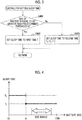
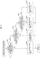
- FIGS. 3 , 5 , and 7 are flowcharts showing a more detailed processing procedure of control for setting the sleep time (Step S40) in FIG. 2 .
- FIGS. 4 , 6 , and 8 are graphs illustrating setting concepts of the sleep time of FIGS. 3 , 5 , and 7 , respectively.
- Electric power saving control shown in FIG. 2 is started when the solar power generation system 1 is operated at power on or the like, and is repeatedly executed until the solar power generation system 1 is stopped at power off or the like.
- Step S10 An instruction to execute the wakeup control is given to the electric power controller 12.
- Step S20 Determination is made whether or not the solar power generation system 1 satisfies a predetermined sleep condition.
- determination is made whether or not the generated electric power of the solar panel 11 is lower than a predetermined value.
- the predetermined value can be, for example, minimum electric power consumption needed when the electric power controller 12 processes the generated electric power of the solar panel 11.
- Step S30 Determination is made whether or not the solar power generation system 1 can be made sleep (a part of functions are stopped or restricted) based on determination regarding whether or not the sleep condition is satisfied.
- Step S30, Yes the process progresses to Step S40, when determination is made that sleep is not possible (Step S30, No), the process returns to Step S20.
- Step S40 The control for setting the sleep time is executed.
- the sleep time defines a time for which the sleep control is continued when the solar power generation system 1 is switched (transits) from the wakeup control to the sleep control.
- the sleep time is dynamically set, for example, based on the state of charge of the battery 13 as shown in a setting example 1 ( FIG. 3 ), a setting example 2 ( FIG. 5 ), and a setting example 3 ( FIG. 7 ) described below.
- Step S401 Determination is made whether or not the state of charge (SOC) of the battery 13 is equal to or greater than a predetermined threshold th.
- the threshold th can be set to be lower than a lower limit value of a state of charge in a range to be normally used in the battery 13.
- Step S402 The sleep time is set to a first time T 1 .
- the process progresses to Step S50 of FIG. 2 .
- Step S403 The sleep time is set to a second time T 2 .
- the second time T2 is set to a time longer than the first time T 1 (T 2 > T 1 ).
- the setting concept of the sleep time that is executed in Steps S401 to S403 according to the setting example 1 is shown in FIG. 4 .
- Step S411 Determination is made whether or not the state of charge (SOC) of the battery 13 is equal to or greater than a first threshold th 1 .
- the first threshold th 1 can be set to be lower than a lower limit value of a state of charge in a range to be normally used in the battery 13.
- Step S412 Determination is made whether or not the state of charge (SOC) of the battery 13 is equal to or greater than a second threshold th 2 .
- the second threshold th 2 is set to be lower than the lower limit value of the state of charge in the range to be normally used in the battery 13 and lower than the first threshold th 1 .
- Step S413 Determination is made whether or not the state of charge (SOC) of the battery 13 is equal to or greater than a third threshold th 3 .
- the third threshold th 3 is set to be lower than the lower limit value of the state of charge in the range to be normally used in the battery 13 and lower than the second threshold th 2 .
- Step S413, Yes the state of charge is equal to or greater than the third threshold th 3 (Step S413, Yes)
- the process progresses to Step S416.
- Step S413, No determination branching is sequentially executed until a threshold th n-1 similarly, and finally, when the state of charge is less than the threshold th n-1 , the process progresses to Step S417.
- Step S414 The sleep time is set to the first time T 1 .
- the process progresses to Step S50 of FIG. 2 .
- Step S415 The sleep time is set to the second time T 2 .
- the second time T2 is set to a time longer than the first time T 1 (T 2 > T 1 ).
- T 2 > T 1 the setting of the sleep time ends, the process progresses to Step S50 of FIG. 2 .
- Step S416 The sleep time is set to a third time T 3 .
- the third time T 3 is set to a time longer than the second time T 2 (T 3 > T 2 ).
- Step S417 The sleep time is set to an n-th Tn.
- the n-th time T n is set to a time longer than an (n-1)th time T n-1 (T n > T n-1 ).
- T n the setting of the sleep time ends, the process progresses to Step S50 of FIG. 2 .
- the variable n can be any integer equal to or greater than 2.
- the setting concept of the sleep time that is executed in Steps S411 to S417 according to the setting example 2 is shown in FIG. 6 .
- a plurality of thresholds is set in such a manner that the longer sleep time is allocated when a numerical value of the threshold is smaller.
- Step S421 Determination is made whether or not the state of charge (SOC) of the battery 13 is equal to or greater than a predetermined threshold th.
- the threshold th can be set to be lower than the lower limit value of the state of charge in the range to be normally used in the battery 13.
- Step S422 The sleep time is set to the first time T 1 .
- the process progresses to Step S50 of FIG. 2 .
- Step S423 The sleep time is obtained through a predetermined arithmetic operation with the state of charge of the battery 13 as an argument, and the obtained sleep time is set to the second time T 2 .
- the second time T 2 is set to a time longer than the first time T 1 (T 2 > T 1 ).
- FIG. 8 The setting concept of the sleep time that is executed in Steps S421 to S423 according to the setting example 3 is shown in FIG. 8 .
- FIG. 8 although an example where a result of the arithmetic operation is obtained as a straight line has been shown, an arithmetic operation may be performed such that a result is obtained as a curve.
- the sleep time can be obtained, for example, by referring to a conversion table in which the state of charge of the battery 13 and the sleep time are associated with each other, instead of the above-described arithmetic operation with the state of charge of the battery 13 as an argument.
- Step S50 An instruction to execute the sleep control is given to the electric power controller 12.
- Step S60 After the instruction to execute the sleep control is given, determination is made that the sleep time set through the control for setting the sleep time in Step S40 elapses. When determination is made that the sleep time has elapsed (Step S60, Yes), the process returns to Step S10.
- the timing when the control for setting the sleep time of Step S40 is executed may be any timing before the instruction to execute the sleep control is given to the electric power controller 12 in Step S50.
- the control for setting the sleep time of Step S40 may be executed (constantly or intermittently) independently of and in parallel with other kinds of control (Steps S10, S20, S30, S50, and S60).
- the sleep time may be controlled based on an internal resistance value of the battery instead of the state of charge.
- the sleep time may be controlled taking into consideration both of the state of charge and the internal resistance value.
- the state (state of charge, internal resistance value, or the like) of the battery is detected using the battery state detection unit 14, and the sleep time for temporarily stopping the solar power generation system 1 is controlled based on the detected state of the battery 13.
- the state of the battery 13 is a state in which electric power consumption is to be suppressed, it is possible to give priority to restraining electric power from being needlessly consumed.
- SOC state of charge
- control for setting the sleep time to be longer than when the state of charge of the battery 13 is equal to or greater than the threshold th when the state of charge of the battery 13 is small, it is possible to restrain electric power of the battery 13 from being needlessly consumed due to frequent repetition of the start (wakeup) and the stop (sleep) of the solar power generation system 1.
- the solar power generation control device and the control method of the invention are available for controlling a solar power generation system mounted in a vehicle, or the like.
Landscapes
- Engineering & Computer Science (AREA)
- Power Engineering (AREA)
- Charge And Discharge Circuits For Batteries Or The Like (AREA)
- Supply And Distribution Of Alternating Current (AREA)
Abstract
Description
- The present invention relates to a solar power generation control device that controls a solar power generation system storing electric power generated by a solar panel in a battery, and a control method that the solar power generation control device executes.
- Japanese Unexamined Patent Application Publication No.
2015-002640 JP 2015-002640 A - In the solar power generation system described in
JP 2015-002640 A - The invention provides a solar power generation control device and a control method capable of suppressing needless consumption of electric power of a battery.
- A first aspect of the invention relates to a solar power generation control device that controls a solar power generation system storing electric power generated by a solar panel in a battery. The solar power generation control device includes a detection unit and a controller. The detection unit is configured to detect a state of the battery. The controller is configured to control, based on the state of the battery, a sleep time for temporarily stopping the solar power generation system when a predetermined sleep condition is satisfied.
- With the solar power generation control device according to the first aspect of the invention, the sleep time for temporarily stopping the solar power generation system is controlled based on the state of the battery. With this, when the state of the battery is a state in which electric power consumption is to be suppressed, it is possible to give priority to suppressing needless consumption of electric power.
- In the solar power generation control device according to the first aspect of the invention, the detection unit may be configured to detect a state of charge as the state of the battery. The controller may be configured to set the sleep time to be longer when the state of charge of the battery is less than a predetermined threshold than when the state of charge of the battery is equal to or greater than the threshold.
- With the solar power generation control device according to the first aspect of the invention, when the state of charge of the battery is small, it is possible to suppress needless consumption of electric power of the battery due to frequent repetition of start and stop of the solar power generation system.
- In the solar power generation control device according to the first aspect of the invention, the detection unit may be configured to detect a state of charge as the state of the battery. The controller may be configured to provide a threshold lower than a lower limit value of the state of charge in a predetermined use range of the battery and set the sleep time to be longer when the state of charge of the battery is less than the threshold than when the state of charge of the battery is equal to or greater than the threshold.
- With the solar power generation control device according to the first aspect of the invention, when the battery is used in a normal use range, since the sleep time is not set to be long wastefully, it is possible to reduce missing an opportunity to use electric power generated by the solar panel.
- In the solar power generation control device according to the first aspect of the invention, the detection unit may be configured to detect the state of charge as the state of the battery. The controller may be configured to provide a plurality of thresholds in such a manner that a longer sleep time is allocated as a numerical value of the threshold is smaller.
- With the solar power generation control device according to the first aspect of the invention, when the state of charge of the battery is small, it is possible to suppress needless consumption of electric power of the battery due to frequent repetition of start and stop of the solar power generation system with high accuracy.
- In the solar power generation control device according to the first aspect of the invention, the controller may be configured to calculate the sleep time through a predetermined arithmetic operation with the state of charge of the battery as an argument.
- In the solar power generation control device according to the first aspect of the invention, the detection unit may be configured to detect an internal resistance value as the state of the battery. The controller may be configured to control the sleep time based on the internal resistance value of the battery.
- Even with the internal resistance value, when the state of the battery is a deterioration state in which electric power consumption is to be suppressed, it is possible to give priority to suppressing needless consumption of electric power.
- A second aspect of the invention relates to a control method that a solar power generation control device configured to control a solar power generation system storing electric power generated by a solar panel in a battery executes. The control method includes detecting a state of the battery, and controlling, based on the state of the battery, a sleep time for temporarily stopping the solar power generation system when a predetermined sleep condition is satisfied.
- With the control method according to the second aspect of the invention, the sleep time for temporarily stopping the solar power generation system is controlled based on the state of the battery. With this, when the state of the battery is a state in which electric power consumption is to be suppressed, it is possible to give priority to suppressing needless consumption of electric power.
- With the solar power generation control device and the control method according to the aspects of the invention, it is possible to suppress needless consumption of the state of charge of the battery.
- Features, advantages, and technical and industrial significance of exemplary embodiments of the invention will be described below with reference to the accompanying drawings, in which like numerals denote like elements, and wherein:
-
FIG. 1 is a diagram showing a configuration example of a solar power generation system including a solar power generation control device according to an embodiment of the invention; -
FIG. 2 is a flowchart showing a processing procedure of an electric power saving control method that a controller executes; -
FIG. 3 is a flowchart (setting example 1) showing a detailed processing procedure of control for setting a sleep time ofFIG.2 ; -
FIG. 4 is a graph illustrating a setting concept of the sleep time ofFIG. 3 ; -
FIG. 5 is a flowchart showing a detailed processing procedure of the control for setting the sleep time ofFIG.2 ; -
FIG. 6 is a graph illustrating a setting concept of the sleep time ofFIG. 5 ; -
FIG. 7 is a flowchart (setting example 3) showing a detailed processing procedure of the control for setting the sleep time ofFIG.2 ; and -
FIG. 8 is a graph illustrating a setting concept of the sleep time ofFIG. 7 . - A solar power generation control device and a control method according to an embodiment are used to control, for example, a solar power generation system or the like mounted in a vehicle. In the solar power generation control device, a sleep time for temporarily stopping the solar power generation system is controlled based on a state of a battery. With this, when the state of the battery is a state in which electric power consumption is to be suppressed, it is possible to give priority to suppressing needless consumption of electric power.
-
FIG. 1 is a diagram showing a configuration example of a solarpower generation system 1 including a solar power generation control device according to an embodiment of the invention. The solarpower generation system 1 illustrated inFIG. 1 includes asolar panel 11, anelectric power controller 12, abattery 13, a batterystate detection unit 14, and acontroller 15. The batterystate detection unit 14 and thecontroller 15 correspond to the solar power generation control device according to the embodiment. - In
FIG. 1 , a wiring in which an electric power signal flows is indicated by a solid line, and a wiring in which a detection signal or a control signal flows is indicated by a dotted line. - The
solar panel 11 is a solar cell module that receives irradiation of sunlight and performs electric power generation. Thesolar panel 11 can be provided, for example, on a roof of the vehicle. Electric power obtained by electric power generation of thesolar panel 11 is output to theelectric power controller 12. - The
electric power controller 12 is a configuration for executing predetermined control on generated electric power of thesolar panel 11. Theelectric power controller 12 can receive generated electric power of thesolar panel 11 as input, can convert the generated electric power to predetermined electric power, and then, can charge thebattery 13 with the predetermined electric power. Theelectric power controller 12 supplies electric power stored in thebattery 13 to predetermined load equipment. Theelectric power controller 12 can perform switching (transition) from "wakeup control" to "sleep control" described below according to an instruction from thecontroller 15 to execute control for reducing electric power consumption. - The
battery 13 is, for example, an electric power storage element configured to be chargeable and dischargeable, such as a nickel-hydrogen battery. Thebattery 13 is connected to theelectric power controller 12 to enable charging with electric power (generated electric power after conversion) to be received from theelectric power controller 12 and discharging of stored electric power to theelectric power controller 12. - The battery
state detection unit 14 is a configuration for detecting a predetermined state (hereinafter, simply referred to as "the state of thebattery 13") relating to thebattery 13. As the state of thebattery 13, for example, a state of charge (SOC), an internal resistance value, or the like is exemplified. In the embodiment, a case where the state of thebattery 13 is the state of charge will be described. The state of charge detected by the batterystate detection unit 14 is output to thecontroller 15. - The
controller 15 is constituted of, for example, a microcomputer. Thecontroller 15 instructs execution of various kinds of control in the solarpower generation system 1 on theelectric power controller 12 based on the generated electric power of thesolar panel 11 acquired from theelectric power controller 12 and the state of charge detected by the batterystate detection unit 14, and the like. Thecontroller 15 can instruct execution of electric power saving control in the solarpower generation system 1 with awakeup function unit 15a and asleep function unit 15b as one of various kinds of control to be instructed. - The
wakeup function unit 15a is a configuration for instructing theelectric power controller 12 to execute "wakeup control" for operating the solarpower generation system 1 in a normal state. The wakeup control is executed immediately after electric power is supplied, or the like, and can operate the solarpower generation system 1. The wakeup control is executed after sleep control described below ends. - The
sleep function unit 15b is a configuration for instructing theelectric power controller 12 to execute "sleep control" for operating the solarpower generation system 1 in an electric power saving state. The sleep control is executed, for example, when a predetermined sleep condition that the generated electric power of thesolar panel 11 is lower than a predetermined value during the above-described wakeup control is satisfied, and can stop or restrict at least a part of functions of the solarpower generation system 1. The sleep control is continuously executed for a sleep time to be dynamically set, and ends when the sleep time has elapsed. A setting method of the sleep time will be described below. - Control of the solar
power generation system 1 that the solar power generation control device according to the embodiment of the invention executes will be described further referring toFIGS. 2 to 8 .FIG. 2 is a flowchart showing a processing procedure of an electric power saving control method that thecontroller 15 according to the embodiment executes.FIGS. 3 ,5 , and7 are flowcharts showing a more detailed processing procedure of control for setting the sleep time (Step S40) inFIG. 2 .FIGS. 4 ,6 , and8 are graphs illustrating setting concepts of the sleep time ofFIGS. 3 ,5 , and7 , respectively. - Electric power saving control shown in
FIG. 2 is started when the solarpower generation system 1 is operated at power on or the like, and is repeatedly executed until the solarpower generation system 1 is stopped at power off or the like. - Step S10: An instruction to execute the wakeup control is given to the
electric power controller 12. - Step S20: Determination is made whether or not the solar
power generation system 1 satisfies a predetermined sleep condition. In the embodiment, as an example, determination is made whether or not the generated electric power of thesolar panel 11 is lower than a predetermined value. The predetermined value can be, for example, minimum electric power consumption needed when theelectric power controller 12 processes the generated electric power of thesolar panel 11. - Step S30: Determination is made whether or not the solar
power generation system 1 can be made sleep (a part of functions are stopped or restricted) based on determination regarding whether or not the sleep condition is satisfied. When determination is made that sleep is possible (Step S30, Yes), the process progresses to Step S40, when determination is made that sleep is not possible (Step S30, No), the process returns to Step S20. - Step S40: The control for setting the sleep time is executed. The sleep time defines a time for which the sleep control is continued when the solar
power generation system 1 is switched (transits) from the wakeup control to the sleep control. The sleep time is dynamically set, for example, based on the state of charge of thebattery 13 as shown in a setting example 1 (FIG. 3 ), a setting example 2 (FIG. 5 ), and a setting example 3 (FIG. 7 ) described below. - Step S401: Determination is made whether or not the state of charge (SOC) of the
battery 13 is equal to or greater than a predetermined threshold th. The threshold th can be set to be lower than a lower limit value of a state of charge in a range to be normally used in thebattery 13. When the state of charge is equal to or greater than the threshold th (Step S401, Yes), the process progresses to Step S402, and when the state of charge is less than the threshold th (Step S401, No), the process progresses to Step S403. - Step S402: The sleep time is set to a first time T1. When the setting of the sleep time ends, the process progresses to Step S50 of
FIG. 2 . - Step S403: The sleep time is set to a second time T2. The second time T2 is set to a time longer than the first time T1 (T2 > T1). When the setting of the sleep time ends, the process progresses to Step S50 of
FIG. 2 . - The setting concept of the sleep time that is executed in Steps S401 to S403 according to the setting example 1 is shown in
FIG. 4 . - Step S411: Determination is made whether or not the state of charge (SOC) of the
battery 13 is equal to or greater than a first threshold th1. The first threshold th1 can be set to be lower than a lower limit value of a state of charge in a range to be normally used in thebattery 13. When the state of charge is equal to or greater than the first threshold th1 (Step S411, Yes), the process progresses to Step S414, and when the state of charge is less than the first threshold th1 (Step S411, No), the process progresses to Step S412. - Step S412: Determination is made whether or not the state of charge (SOC) of the
battery 13 is equal to or greater than a second threshold th2. The second threshold th2 is set to be lower than the lower limit value of the state of charge in the range to be normally used in thebattery 13 and lower than the first threshold th1. When the state of charge is equal to or greater than the second threshold th2 (Step S412, Yes), the process progresses to Step S415, and when the state of charge is less than the second threshold th2 (Step S412, No), the process progresses to Step S413. - Step S413: Determination is made whether or not the state of charge (SOC) of the
battery 13 is equal to or greater than a third threshold th3. The third threshold th3 is set to be lower than the lower limit value of the state of charge in the range to be normally used in thebattery 13 and lower than the second threshold th2. When the state of charge is equal to or greater than the third threshold th3 (Step S413, Yes), the process progresses to Step S416. When the state of charge is less than the third threshold th3 (Step S413, No), hereinafter, determination branching is sequentially executed until a threshold thn-1 similarly, and finally, when the state of charge is less than the threshold thn-1, the process progresses to Step S417. - Step S414: The sleep time is set to the first time T1. When the setting of the sleep time ends, the process progresses to Step S50 of
FIG. 2 . - Step S415: The sleep time is set to the second time T2. The second time T2 is set to a time longer than the first time T1 (T2 > T1). When the setting of the sleep time ends, the process progresses to Step S50 of
FIG. 2 . - Step S416: The sleep time is set to a third time T3. The third time T3 is set to a time longer than the second time T2 (T3 > T2). When the setting of the sleep time ends, the process progresses to Step S50 of
FIG. 2 . - Step S417: The sleep time is set to an n-th Tn. The n-th time Tn is set to a time longer than an (n-1)th time Tn-1 (Tn > Tn-1). When the setting of the sleep time ends, the process progresses to Step S50 of
FIG. 2 . The variable n can be any integer equal to or greater than 2. - The setting concept of the sleep time that is executed in Steps S411 to S417 according to the setting example 2 is shown in
FIG. 6 . In the setting example 2, a plurality of thresholds is set in such a manner that the longer sleep time is allocated when a numerical value of the threshold is smaller. - Step S421: Determination is made whether or not the state of charge (SOC) of the
battery 13 is equal to or greater than a predetermined threshold th. The threshold th can be set to be lower than the lower limit value of the state of charge in the range to be normally used in thebattery 13. When the state of charge is equal to or greater than the threshold th (Step S421, Yes), the process progresses to Step S422, and when the state of charge is less than the threshold th (Step S421, No), the process progresses to Step S423. - Step S422: The sleep time is set to the first time T1. When the setting of the sleep time ends, the process progresses to Step S50 of
FIG. 2 . - Step S423: The sleep time is obtained through a predetermined arithmetic operation with the state of charge of the
battery 13 as an argument, and the obtained sleep time is set to the second time T2. The second time T2 is set to a time longer than the first time T1 (T2 > T1). When the setting of the sleep time ends, the process progresses to Step S50 ofFIG. 2 . - The setting concept of the sleep time that is executed in Steps S421 to S423 according to the setting example 3 is shown in
FIG. 8 . InFIG. 8 , although an example where a result of the arithmetic operation is obtained as a straight line has been shown, an arithmetic operation may be performed such that a result is obtained as a curve. - The sleep time can be obtained, for example, by referring to a conversion table in which the state of charge of the
battery 13 and the sleep time are associated with each other, instead of the above-described arithmetic operation with the state of charge of thebattery 13 as an argument. - Step S50: An instruction to execute the sleep control is given to the
electric power controller 12. - Step S60: After the instruction to execute the sleep control is given, determination is made that the sleep time set through the control for setting the sleep time in Step S40 elapses. When determination is made that the sleep time has elapsed (Step S60, Yes), the process returns to Step S10.
- In the flowchart of
FIG. 2 , the timing when the control for setting the sleep time of Step S40 is executed may be any timing before the instruction to execute the sleep control is given to theelectric power controller 12 in Step S50. The control for setting the sleep time of Step S40 may be executed (constantly or intermittently) independently of and in parallel with other kinds of control (Steps S10, S20, S30, S50, and S60). - In the embodiment, although an example where the sleep time is controlled based on the state of charge as the state of the battery has been described above, the sleep time may be controlled based on an internal resistance value of the battery instead of the state of charge. The sleep time may be controlled taking into consideration both of the state of charge and the internal resistance value.
- With the solar power generation control device and the control method according to the embodiment of the invention, the state (state of charge, internal resistance value, or the like) of the battery is detected using the battery
state detection unit 14, and the sleep time for temporarily stopping the solarpower generation system 1 is controlled based on the detected state of thebattery 13. - With this, when the state of the
battery 13 is a state in which electric power consumption is to be suppressed, it is possible to give priority to restraining electric power from being needlessly consumed. For example, when the state of charge (SOC) of thebattery 13 is less than the predetermined threshold th, control for setting the sleep time to be longer than when the state of charge of thebattery 13 is equal to or greater than the threshold th. With the above-described control, when the state of charge of thebattery 13 is small, it is possible to restrain electric power of thebattery 13 from being needlessly consumed due to frequent repetition of the start (wakeup) and the stop (sleep) of the solarpower generation system 1. - The solar power generation control device and the control method of the invention are available for controlling a solar power generation system mounted in a vehicle, or the like.
Claims (7)
- A solar power generation control device that controls a solar power generation system (1) storing electric power generated by a solar panel (11) in a battery (13), the solar power generation control device comprising:a detection unit (14) configured to detect a state of the battery (13); anda controller (15) configured to control, based on the state of the battery (13), a sleep time for temporarily stopping the solar power generation system (1) when a predetermined sleep condition is satisfied.
- The solar power generation control device according to claim 1, wherein:the detection unit (14) is configured to detect a state of charge as the state of the battery (13); andthe controller (15) is configured to set the sleep time to be longer when the state of charge of the battery (13) is less than a predetermined threshold than when the state of charge of the battery (13) is equal to or greater than the threshold.
- The solar power generation control device according to claim 1, wherein:the detection unit (14) is configured to detect a state of charge as the state of the battery (13); andthe controller (15) is configured to provide a threshold lower than a lower limit value of the state of charge in a predetermined use range of the battery (13) and set the sleep time to be longer when the state of charge of the battery (13) is less than the threshold than when the state of charge of the battery (13) is equal to or greater than the threshold.
- The solar power generation control device according to claim 3, wherein:the detection unit (14) is configured to detect the state of charge as the state of the battery (13); andthe controller (15) is configured to provide a plurality of thresholds in such a manner that a longer sleep time is allocated as a numerical value of the threshold is smaller.
- The solar power generation control device according to any one of claims 2 to 4, wherein the controller (15) is configured to calculate the sleep time through a predetermined arithmetic operation with the state of charge of the battery (13) as an argument.
- The solar power generation control device according to claim 1, wherein:the detection unit (14) is configured to detect an internal resistance value as the state of the battery (13); andthe controller (15) is configured to control the sleep time based on the internal resistance value of the battery (13).
- A control method that a solar power generation control device configured to control a solar power generation system (1) storing electric power generated by a solar panel (11) in a battery (13) executes, the control method comprising:detecting a state of the battery (13); andcontrolling, based on the state of the battery (13), a sleep time for temporarily stopping the solar power generation system (1) when a predetermined sleep condition is satisfied.
Applications Claiming Priority (1)
| Application Number | Priority Date | Filing Date | Title |
|---|---|---|---|
| JP2017244125A JP6935740B2 (en) | 2017-12-20 | 2017-12-20 | Solar power generation control device and control method |
Publications (2)
| Publication Number | Publication Date |
|---|---|
| EP3503346A1 true EP3503346A1 (en) | 2019-06-26 |
| EP3503346B1 EP3503346B1 (en) | 2020-03-04 |
Family
ID=64402129
Family Applications (1)
| Application Number | Title | Priority Date | Filing Date |
|---|---|---|---|
| EP18207339.5A Active EP3503346B1 (en) | 2017-12-20 | 2018-11-20 | Solar power generation control device and control method |
Country Status (4)
| Country | Link |
|---|---|
| US (2) | US11128163B2 (en) |
| EP (1) | EP3503346B1 (en) |
| JP (1) | JP6935740B2 (en) |
| CN (1) | CN109950964B (en) |
Families Citing this family (6)
| Publication number | Priority date | Publication date | Assignee | Title |
|---|---|---|---|---|
| JP7497183B2 (en) * | 2020-03-19 | 2024-06-10 | 本田技研工業株式会社 | Photovoltaic power generation control device |
| US11553618B2 (en) * | 2020-08-26 | 2023-01-10 | PassiveLogic, Inc. | Methods and systems of building automation state load and user preference via network systems activity |
| US12081063B2 (en) | 2021-07-12 | 2024-09-03 | PassiveLogic, Inc. | Device energy use determination |
| US12250099B2 (en) * | 2021-09-08 | 2025-03-11 | PassiveLogic, Inc. | External activation of quiescent device |
| EP4697938A1 (en) * | 2023-04-18 | 2026-02-25 | Boum AG | Method for irrigating plants with an irrigation system |
| KR102766768B1 (en) * | 2024-10-14 | 2025-02-13 | 유한회사 해신 | Module Integrated Controls and integrated control method using it |
Citations (4)
| Publication number | Priority date | Publication date | Assignee | Title |
|---|---|---|---|---|
| US20140176043A1 (en) * | 2011-05-12 | 2014-06-26 | Sharp Kabushiki Kaisha | Charging control unit |
| JP2015002640A (en) | 2013-06-18 | 2015-01-05 | トヨタ自動車株式会社 | Charge control device |
| JP2016158396A (en) * | 2015-02-24 | 2016-09-01 | 本田技研工業株式会社 | Start determination device of photovoltaic power generation |
| US20170310141A1 (en) * | 2011-01-26 | 2017-10-26 | Mohamed Papa Talla Fall | Energy converting apparatus and method |
Family Cites Families (12)
| Publication number | Priority date | Publication date | Assignee | Title |
|---|---|---|---|---|
| KR100818519B1 (en) * | 2006-05-04 | 2008-03-31 | 주식회사 엘지화학 | Battery care methods and devices |
| US7546477B2 (en) * | 2006-12-29 | 2009-06-09 | General Electric Company | Wake interval adjustment based on charge level |
| US20100207571A1 (en) * | 2009-02-19 | 2010-08-19 | SunCore Corporation | Solar chargeable battery for portable devices |
| WO2011146783A1 (en) * | 2010-05-21 | 2011-11-24 | Qnovo Inc. | Method and circuitry to adaptively charge a battery/cell |
| US9136709B2 (en) * | 2011-10-26 | 2015-09-15 | General Electric Company | Methods and systems for selectively coupling a power conversion system to an electrical grid |
| JP5919857B2 (en) * | 2012-02-03 | 2016-05-18 | スズキ株式会社 | Charge / discharge control device |
| US9559536B2 (en) * | 2014-04-30 | 2017-01-31 | Johnson Controls Technology Company | State of charge indicator method and system |
| JP5969575B2 (en) * | 2014-11-14 | 2016-08-17 | イーソル株式会社 | Photovoltaic power generation system and charging control method in solar power generation system |
| US10193366B2 (en) * | 2015-01-12 | 2019-01-29 | Potential Difference, Inc. | Rapid battery charging |
| JP6380435B2 (en) * | 2016-03-16 | 2018-08-29 | トヨタ自動車株式会社 | Vehicle solar cell system |
| CN106787114B (en) * | 2017-01-20 | 2024-01-16 | 国家电网公司 | Embedded wearable solar power supply system and control method thereof |
| CN106877450B (en) * | 2017-03-31 | 2019-06-28 | 深圳市电科电源股份有限公司 | A kind of family energy-storage system low battery control method |
-
2017
- 2017-12-20 JP JP2017244125A patent/JP6935740B2/en active Active
-
2018
- 2018-11-16 US US16/193,234 patent/US11128163B2/en active Active
- 2018-11-20 EP EP18207339.5A patent/EP3503346B1/en active Active
- 2018-12-04 CN CN201811476069.6A patent/CN109950964B/en active Active
-
2021
- 2021-08-13 US US17/402,136 patent/US11979054B2/en active Active
Patent Citations (5)
| Publication number | Priority date | Publication date | Assignee | Title |
|---|---|---|---|---|
| US20170310141A1 (en) * | 2011-01-26 | 2017-10-26 | Mohamed Papa Talla Fall | Energy converting apparatus and method |
| US20140176043A1 (en) * | 2011-05-12 | 2014-06-26 | Sharp Kabushiki Kaisha | Charging control unit |
| JP2015002640A (en) | 2013-06-18 | 2015-01-05 | トヨタ自動車株式会社 | Charge control device |
| US20160134157A1 (en) * | 2013-06-18 | 2016-05-12 | Toyota Jidosha Kabushiki Kaisha | Charge control device |
| JP2016158396A (en) * | 2015-02-24 | 2016-09-01 | 本田技研工業株式会社 | Start determination device of photovoltaic power generation |
Also Published As
| Publication number | Publication date |
|---|---|
| US11128163B2 (en) | 2021-09-21 |
| CN109950964B (en) | 2022-05-31 |
| JP2019110731A (en) | 2019-07-04 |
| JP6935740B2 (en) | 2021-09-15 |
| US20210376653A1 (en) | 2021-12-02 |
| US11979054B2 (en) | 2024-05-07 |
| CN109950964A (en) | 2019-06-28 |
| EP3503346B1 (en) | 2020-03-04 |
| US20190190308A1 (en) | 2019-06-20 |
Similar Documents
| Publication | Publication Date | Title |
|---|---|---|
| EP3503346B1 (en) | Solar power generation control device and control method | |
| US11338689B2 (en) | System and method for controlling vehicle including solar cell | |
| US8533509B2 (en) | Device and method for controlling secondary battery | |
| EP2816701B1 (en) | Adjusting device, battery assembly, and adjusting method | |
| US9472960B2 (en) | Regulating device, battery assembly device and regulating method | |
| US11198366B2 (en) | Solar power generation system | |
| JP2021083248A (en) | Solar charging system | |
| US9413037B2 (en) | Cell capacity adjusting device | |
| US20190074711A1 (en) | Charge control system and charge control method | |
| JP5657257B2 (en) | Charging system | |
| CN115776152A (en) | Control method and system for combined power supply of solar panel and storage battery | |
| JP2022055172A (en) | Charge/discharge control system | |
| US10571524B2 (en) | In-vehicle power supply device | |
| US20230063555A1 (en) | Control device, control method, and non-transitory storage medium | |
| US20190047420A1 (en) | Electric power control device and vehicle | |
| JP2023075747A (en) | Vehicle power control device, power control method, and vehicle | |
| JP7473070B1 (en) | Vehicle Control Systems | |
| US20260045817A1 (en) | Rechargeable battery system | |
| US10613152B2 (en) | Battery monitoring device and power state monitoring method | |
| US20240326624A1 (en) | Solar charging system | |
| US12489389B2 (en) | Solar charging system | |
| JP2019050713A (en) | Charge control system and charge control method | |
| JP2025085183A (en) | Power System | |
| JP2024141611A (en) | Solar Charging System | |
| JP2022089059A (en) | Fuel cell system |
Legal Events
| Date | Code | Title | Description |
|---|---|---|---|
| PUAI | Public reference made under article 153(3) epc to a published international application that has entered the european phase |
Free format text: ORIGINAL CODE: 0009012 |
|
| STAA | Information on the status of an ep patent application or granted ep patent |
Free format text: STATUS: REQUEST FOR EXAMINATION WAS MADE |
|
| 17P | Request for examination filed |
Effective date: 20181120 |
|
| AK | Designated contracting states |
Kind code of ref document: A1 Designated state(s): AL AT BE BG CH CY CZ DE DK EE ES FI FR GB GR HR HU IE IS IT LI LT LU LV MC MK MT NL NO PL PT RO RS SE SI SK SM TR |
|
| AX | Request for extension of the european patent |
Extension state: BA ME |
|
| GRAP | Despatch of communication of intention to grant a patent |
Free format text: ORIGINAL CODE: EPIDOSNIGR1 |
|
| STAA | Information on the status of an ep patent application or granted ep patent |
Free format text: STATUS: GRANT OF PATENT IS INTENDED |
|
| RIC1 | Information provided on ipc code assigned before grant |
Ipc: H02J 7/04 20060101AFI20190828BHEP Ipc: H02J 7/00 20060101ALI20190828BHEP Ipc: H02J 7/35 20060101ALI20190828BHEP |
|
| INTG | Intention to grant announced |
Effective date: 20191002 |
|
| GRAS | Grant fee paid |
Free format text: ORIGINAL CODE: EPIDOSNIGR3 |
|
| GRAA | (expected) grant |
Free format text: ORIGINAL CODE: 0009210 |
|
| STAA | Information on the status of an ep patent application or granted ep patent |
Free format text: STATUS: THE PATENT HAS BEEN GRANTED |
|
| AK | Designated contracting states |
Kind code of ref document: B1 Designated state(s): AL AT BE BG CH CY CZ DE DK EE ES FI FR GB GR HR HU IE IS IT LI LT LU LV MC MK MT NL NO PL PT RO RS SE SI SK SM TR |
|
| REG | Reference to a national code |
Ref country code: GB Ref legal event code: FG4D |
|
| REG | Reference to a national code |
Ref country code: CH Ref legal event code: EP |
|
| REG | Reference to a national code |
Ref country code: AT Ref legal event code: REF Ref document number: 1241492 Country of ref document: AT Kind code of ref document: T Effective date: 20200315 |
|
| REG | Reference to a national code |
Ref country code: DE Ref legal event code: R096 Ref document number: 602018002867 Country of ref document: DE |
|
| REG | Reference to a national code |
Ref country code: IE Ref legal event code: FG4D |
|
| PG25 | Lapsed in a contracting state [announced via postgrant information from national office to epo] |
Ref country code: FI Free format text: LAPSE BECAUSE OF FAILURE TO SUBMIT A TRANSLATION OF THE DESCRIPTION OR TO PAY THE FEE WITHIN THE PRESCRIBED TIME-LIMIT Effective date: 20200304 Ref country code: RS Free format text: LAPSE BECAUSE OF FAILURE TO SUBMIT A TRANSLATION OF THE DESCRIPTION OR TO PAY THE FEE WITHIN THE PRESCRIBED TIME-LIMIT Effective date: 20200304 Ref country code: NO Free format text: LAPSE BECAUSE OF FAILURE TO SUBMIT A TRANSLATION OF THE DESCRIPTION OR TO PAY THE FEE WITHIN THE PRESCRIBED TIME-LIMIT Effective date: 20200604 |
|
| REG | Reference to a national code |
Ref country code: NL Ref legal event code: MP Effective date: 20200304 |
|
| PG25 | Lapsed in a contracting state [announced via postgrant information from national office to epo] |
Ref country code: GR Free format text: LAPSE BECAUSE OF FAILURE TO SUBMIT A TRANSLATION OF THE DESCRIPTION OR TO PAY THE FEE WITHIN THE PRESCRIBED TIME-LIMIT Effective date: 20200605 Ref country code: HR Free format text: LAPSE BECAUSE OF FAILURE TO SUBMIT A TRANSLATION OF THE DESCRIPTION OR TO PAY THE FEE WITHIN THE PRESCRIBED TIME-LIMIT Effective date: 20200304 Ref country code: LV Free format text: LAPSE BECAUSE OF FAILURE TO SUBMIT A TRANSLATION OF THE DESCRIPTION OR TO PAY THE FEE WITHIN THE PRESCRIBED TIME-LIMIT Effective date: 20200304 Ref country code: SE Free format text: LAPSE BECAUSE OF FAILURE TO SUBMIT A TRANSLATION OF THE DESCRIPTION OR TO PAY THE FEE WITHIN THE PRESCRIBED TIME-LIMIT Effective date: 20200304 Ref country code: BG Free format text: LAPSE BECAUSE OF FAILURE TO SUBMIT A TRANSLATION OF THE DESCRIPTION OR TO PAY THE FEE WITHIN THE PRESCRIBED TIME-LIMIT Effective date: 20200604 |
|
| REG | Reference to a national code |
Ref country code: LT Ref legal event code: MG4D |
|
| PG25 | Lapsed in a contracting state [announced via postgrant information from national office to epo] |
Ref country code: NL Free format text: LAPSE BECAUSE OF FAILURE TO SUBMIT A TRANSLATION OF THE DESCRIPTION OR TO PAY THE FEE WITHIN THE PRESCRIBED TIME-LIMIT Effective date: 20200304 |
|
| PG25 | Lapsed in a contracting state [announced via postgrant information from national office to epo] |
Ref country code: LT Free format text: LAPSE BECAUSE OF FAILURE TO SUBMIT A TRANSLATION OF THE DESCRIPTION OR TO PAY THE FEE WITHIN THE PRESCRIBED TIME-LIMIT Effective date: 20200304 Ref country code: ES Free format text: LAPSE BECAUSE OF FAILURE TO SUBMIT A TRANSLATION OF THE DESCRIPTION OR TO PAY THE FEE WITHIN THE PRESCRIBED TIME-LIMIT Effective date: 20200304 Ref country code: IS Free format text: LAPSE BECAUSE OF FAILURE TO SUBMIT A TRANSLATION OF THE DESCRIPTION OR TO PAY THE FEE WITHIN THE PRESCRIBED TIME-LIMIT Effective date: 20200704 Ref country code: RO Free format text: LAPSE BECAUSE OF FAILURE TO SUBMIT A TRANSLATION OF THE DESCRIPTION OR TO PAY THE FEE WITHIN THE PRESCRIBED TIME-LIMIT Effective date: 20200304 Ref country code: CZ Free format text: LAPSE BECAUSE OF FAILURE TO SUBMIT A TRANSLATION OF THE DESCRIPTION OR TO PAY THE FEE WITHIN THE PRESCRIBED TIME-LIMIT Effective date: 20200304 Ref country code: SK Free format text: LAPSE BECAUSE OF FAILURE TO SUBMIT A TRANSLATION OF THE DESCRIPTION OR TO PAY THE FEE WITHIN THE PRESCRIBED TIME-LIMIT Effective date: 20200304 Ref country code: SM Free format text: LAPSE BECAUSE OF FAILURE TO SUBMIT A TRANSLATION OF THE DESCRIPTION OR TO PAY THE FEE WITHIN THE PRESCRIBED TIME-LIMIT Effective date: 20200304 Ref country code: EE Free format text: LAPSE BECAUSE OF FAILURE TO SUBMIT A TRANSLATION OF THE DESCRIPTION OR TO PAY THE FEE WITHIN THE PRESCRIBED TIME-LIMIT Effective date: 20200304 Ref country code: PT Free format text: LAPSE BECAUSE OF FAILURE TO SUBMIT A TRANSLATION OF THE DESCRIPTION OR TO PAY THE FEE WITHIN THE PRESCRIBED TIME-LIMIT Effective date: 20200729 |
|
| REG | Reference to a national code |
Ref country code: AT Ref legal event code: MK05 Ref document number: 1241492 Country of ref document: AT Kind code of ref document: T Effective date: 20200304 |
|
| REG | Reference to a national code |
Ref country code: DE Ref legal event code: R097 Ref document number: 602018002867 Country of ref document: DE |
|
| PLBE | No opposition filed within time limit |
Free format text: ORIGINAL CODE: 0009261 |
|
| STAA | Information on the status of an ep patent application or granted ep patent |
Free format text: STATUS: NO OPPOSITION FILED WITHIN TIME LIMIT |
|
| PG25 | Lapsed in a contracting state [announced via postgrant information from national office to epo] |
Ref country code: DK Free format text: LAPSE BECAUSE OF FAILURE TO SUBMIT A TRANSLATION OF THE DESCRIPTION OR TO PAY THE FEE WITHIN THE PRESCRIBED TIME-LIMIT Effective date: 20200304 Ref country code: AT Free format text: LAPSE BECAUSE OF FAILURE TO SUBMIT A TRANSLATION OF THE DESCRIPTION OR TO PAY THE FEE WITHIN THE PRESCRIBED TIME-LIMIT Effective date: 20200304 Ref country code: IT Free format text: LAPSE BECAUSE OF FAILURE TO SUBMIT A TRANSLATION OF THE DESCRIPTION OR TO PAY THE FEE WITHIN THE PRESCRIBED TIME-LIMIT Effective date: 20200304 |
|
| 26N | No opposition filed |
Effective date: 20201207 |
|
| PG25 | Lapsed in a contracting state [announced via postgrant information from national office to epo] |
Ref country code: PL Free format text: LAPSE BECAUSE OF FAILURE TO SUBMIT A TRANSLATION OF THE DESCRIPTION OR TO PAY THE FEE WITHIN THE PRESCRIBED TIME-LIMIT Effective date: 20200304 |
|
| PG25 | Lapsed in a contracting state [announced via postgrant information from national office to epo] |
Ref country code: MC Free format text: LAPSE BECAUSE OF FAILURE TO SUBMIT A TRANSLATION OF THE DESCRIPTION OR TO PAY THE FEE WITHIN THE PRESCRIBED TIME-LIMIT Effective date: 20200304 |
|
| PG25 | Lapsed in a contracting state [announced via postgrant information from national office to epo] |
Ref country code: LU Free format text: LAPSE BECAUSE OF NON-PAYMENT OF DUE FEES Effective date: 20201120 |
|
| REG | Reference to a national code |
Ref country code: BE Ref legal event code: MM Effective date: 20201130 |
|
| PG25 | Lapsed in a contracting state [announced via postgrant information from national office to epo] |
Ref country code: IE Free format text: LAPSE BECAUSE OF NON-PAYMENT OF DUE FEES Effective date: 20201120 |
|
| PG25 | Lapsed in a contracting state [announced via postgrant information from national office to epo] |
Ref country code: TR Free format text: LAPSE BECAUSE OF FAILURE TO SUBMIT A TRANSLATION OF THE DESCRIPTION OR TO PAY THE FEE WITHIN THE PRESCRIBED TIME-LIMIT Effective date: 20200304 Ref country code: MT Free format text: LAPSE BECAUSE OF FAILURE TO SUBMIT A TRANSLATION OF THE DESCRIPTION OR TO PAY THE FEE WITHIN THE PRESCRIBED TIME-LIMIT Effective date: 20200304 Ref country code: CY Free format text: LAPSE BECAUSE OF FAILURE TO SUBMIT A TRANSLATION OF THE DESCRIPTION OR TO PAY THE FEE WITHIN THE PRESCRIBED TIME-LIMIT Effective date: 20200304 |
|
| PG25 | Lapsed in a contracting state [announced via postgrant information from national office to epo] |
Ref country code: MK Free format text: LAPSE BECAUSE OF FAILURE TO SUBMIT A TRANSLATION OF THE DESCRIPTION OR TO PAY THE FEE WITHIN THE PRESCRIBED TIME-LIMIT Effective date: 20200304 Ref country code: AL Free format text: LAPSE BECAUSE OF FAILURE TO SUBMIT A TRANSLATION OF THE DESCRIPTION OR TO PAY THE FEE WITHIN THE PRESCRIBED TIME-LIMIT Effective date: 20200304 |
|
| REG | Reference to a national code |
Ref country code: CH Ref legal event code: PL |
|
| PG25 | Lapsed in a contracting state [announced via postgrant information from national office to epo] |
Ref country code: BE Free format text: LAPSE BECAUSE OF NON-PAYMENT OF DUE FEES Effective date: 20201130 |
|
| REG | Reference to a national code |
Ref country code: DE Ref legal event code: R084 Ref document number: 602018002867 Country of ref document: DE |
|
| REG | Reference to a national code |
Ref country code: GB Ref legal event code: 746 Effective date: 20230103 |
|
| P01 | Opt-out of the competence of the unified patent court (upc) registered |
Effective date: 20230427 |
|
| PG25 | Lapsed in a contracting state [announced via postgrant information from national office to epo] |
Ref country code: LI Free format text: LAPSE BECAUSE OF NON-PAYMENT OF DUE FEES Effective date: 20220630 Ref country code: CH Free format text: LAPSE BECAUSE OF NON-PAYMENT OF DUE FEES Effective date: 20220630 |
|
| PG25 | Lapsed in a contracting state [announced via postgrant information from national office to epo] |
Ref country code: SI Free format text: LAPSE BECAUSE OF FAILURE TO SUBMIT A TRANSLATION OF THE DESCRIPTION OR TO PAY THE FEE WITHIN THE PRESCRIBED TIME-LIMIT Effective date: 20200304 |
|
| PGFP | Annual fee paid to national office [announced via postgrant information from national office to epo] |
Ref country code: FR Payment date: 20250930 Year of fee payment: 8 |
|
| PGFP | Annual fee paid to national office [announced via postgrant information from national office to epo] |
Ref country code: DE Payment date: 20250930 Year of fee payment: 8 |
|
| PGFP | Annual fee paid to national office [announced via postgrant information from national office to epo] |
Ref country code: GB Payment date: 20251001 Year of fee payment: 8 |