EP3503344A1 - Optimized adaptive charging method for strobe - Google Patents
Optimized adaptive charging method for strobe Download PDFInfo
- Publication number
- EP3503344A1 EP3503344A1 EP18213377.7A EP18213377A EP3503344A1 EP 3503344 A1 EP3503344 A1 EP 3503344A1 EP 18213377 A EP18213377 A EP 18213377A EP 3503344 A1 EP3503344 A1 EP 3503344A1
- Authority
- EP
- European Patent Office
- Prior art keywords
- energy
- charge
- current
- predetermined interval
- charge level
- Prior art date
- Legal status (The legal status is an assumption and is not a legal conclusion. Google has not performed a legal analysis and makes no representation as to the accuracy of the status listed.)
- Granted
Links
Images


Classifications
-
- H—ELECTRICITY
- H02—GENERATION; CONVERSION OR DISTRIBUTION OF ELECTRIC POWER
- H02J—ELECTRIC POWER NETWORKS; CIRCUIT ARRANGEMENTS OR SYSTEMS FOR SUPPLYING OR DISTRIBUTING ELECTRIC POWER; SYSTEMS FOR STORING ELECTRIC ENERGY
- H02J7/00—Circuit arrangements for charging or discharging batteries or for supplying loads from batteries
- H02J7/90—Regulation of charging or discharging current or voltage
- H02J7/933—Regulation of charging or discharging current or voltage the cycle being controlled or terminated in response to electric parameters
-
- G—PHYSICS
- G08—SIGNALLING
- G08B—SIGNALLING SYSTEMS, e.g. PERSONAL CALLING SYSTEMS; ORDER TELEGRAPHS; ALARM SYSTEMS
- G08B29/00—Checking or monitoring of signalling or alarm systems; Prevention or correction of operating errors, e.g. preventing unauthorised operation
- G08B29/18—Prevention or correction of operating errors
- G08B29/181—Prevention or correction of operating errors due to failing power supply
-
- G—PHYSICS
- G08—SIGNALLING
- G08B—SIGNALLING SYSTEMS, e.g. PERSONAL CALLING SYSTEMS; ORDER TELEGRAPHS; ALARM SYSTEMS
- G08B5/00—Visible signalling systems, e.g. visible personal calling systems or remote indication of seats occupied
- G08B5/22—Visible signalling systems, e.g. visible personal calling systems or remote indication of seats occupied using electric transmission; using electromagnetic transmission
- G08B5/36—Visible signalling systems, e.g. visible personal calling systems or remote indication of seats occupied using electric transmission; using electromagnetic transmission using visible light sources
- G08B5/38—Visible signalling systems, e.g. visible personal calling systems or remote indication of seats occupied using electric transmission; using electromagnetic transmission using visible light sources using flashing light
-
- H—ELECTRICITY
- H02—GENERATION; CONVERSION OR DISTRIBUTION OF ELECTRIC POWER
- H02J—ELECTRIC POWER NETWORKS; CIRCUIT ARRANGEMENTS OR SYSTEMS FOR SUPPLYING OR DISTRIBUTING ELECTRIC POWER; SYSTEMS FOR STORING ELECTRIC ENERGY
- H02J7/00—Circuit arrangements for charging or discharging batteries or for supplying loads from batteries
-
- H—ELECTRICITY
- H02—GENERATION; CONVERSION OR DISTRIBUTION OF ELECTRIC POWER
- H02J—ELECTRIC POWER NETWORKS; CIRCUIT ARRANGEMENTS OR SYSTEMS FOR SUPPLYING OR DISTRIBUTING ELECTRIC POWER; SYSTEMS FOR STORING ELECTRIC ENERGY
- H02J7/00—Circuit arrangements for charging or discharging batteries or for supplying loads from batteries
- H02J7/865—Battery or charger load switching, e.g. concurrent charging and load supply
-
- H—ELECTRICITY
- H02—GENERATION; CONVERSION OR DISTRIBUTION OF ELECTRIC POWER
- H02J—ELECTRIC POWER NETWORKS; CIRCUIT ARRANGEMENTS OR SYSTEMS FOR SUPPLYING OR DISTRIBUTING ELECTRIC POWER; SYSTEMS FOR STORING ELECTRIC ENERGY
- H02J7/00—Circuit arrangements for charging or discharging batteries or for supplying loads from batteries
- H02J7/34—Parallel operation in networks using both storage and other DC sources, e.g. providing buffering
- H02J7/345—Parallel operation in networks using both storage and other DC sources, e.g. providing buffering using capacitors as storage or buffering devices
-
- H—ELECTRICITY
- H05—ELECTRIC TECHNIQUES NOT OTHERWISE PROVIDED FOR
- H05B—ELECTRIC HEATING; ELECTRIC LIGHT SOURCES NOT OTHERWISE PROVIDED FOR; CIRCUIT ARRANGEMENTS FOR ELECTRIC LIGHT SOURCES, IN GENERAL
- H05B41/00—Circuit arrangements or apparatus for igniting or operating discharge lamps
- H05B41/14—Circuit arrangements
- H05B41/30—Circuit arrangements in which the lamp is fed by pulses, e.g. flash lamp
- H05B41/34—Circuit arrangements in which the lamp is fed by pulses, e.g. flash lamp to provide a sequence of flashes
Definitions
- Fire alarm and mass notification systems are used to notify the public of the presence of fire, smoke and other potentially harmful conditions.
- a notification appliance circuit may be part of such a system and include many notification devices powered and controlled by a common power source and control panel.
- a strobe notification appliance may be utilized as part of a NAC and is a warning device with a light engine, an energy store and a flash control. Strobes that are part of a NAC are required to flash in a synchronized manner.
- the strobe notification appliance provides a brief intense flash of light at predetermined intervals. The brief intense flash requires more power than is practically provided over the circuit to many different strobes. Accordingly, an energy store in each strobe notification appliance buffers energy used for each flash.
- a significant amount of variability can exist in components of each notification appliance due to manufacturing tolerances and thermal effects.
- the variability in the components can cause variability in light level and current drawn from the NAC.
- the variability within each strobe appliance creates challenges in delivering the minimum rated light output at a low current draw from the NAC.
- a notification appliance includes, among other possible things a light engine for generating light flashes at a predetermined interval.
- An energy store supplies energy to the light engine to generate the light flashes at the predetermined interval.
- a charge controller charges the energy store to a full charge level required to generate the light flashes. The charge controller controls an input current to charge the energy store to reach the full charge level at the predetermined interval.
- the charge controller includes a feed forward model that determines a predicted input current required to recharge the energy store at the predetermined interval.
- the predicted input current is based on performance of components in the notification appliance operating within nominal values.
- the current controller includes an adaptive feedback loop that generates a correction value for adjusting the predicted input current based on deviations from the nominal values of the components of the notification appliance.
- the adaptive feedback loop generates the correction value based on environmental conditions surrounding the notification appliance.
- the charge controller includes an inverse model to set the input current to a constant value such that a ratio of a peak current to an average current is between about 0.9 and 1.1.
- the charge controller includes an inverse model to set the input current to a constant value such that a ratio of a peak current to an average current is between about 1:1.
- the energy storage device is discharged to a low charge level after generation of a light flash and charged from the low charge level to the full charge level at an increasing rate for the substantially the entire predetermined interval.
- any of the foregoing notification appliances includes a sample and hold that captures the charge state of the energy store at a beginning and end of a discharge cycle.
- the charge controller supplies a charging current according to a charge level profile determined to charge the energy store from a low charge point after the discharge cycle to the full charge level at the end of the predetermined interval.
- the predetermined interval is between 0.9 and 1.1 seconds.
- An energy discharge device includes, among other possible things, a discharge component generating a high energy event at a predetermined interval.
- An energy store device supplies energy to the discharge component to generate the high energy event at the predetermined interval.
- a charge controller charges the energy storage device to a full charge level required to generate the high energy event.
- the current controller controls the input current to charge the energy store to reach the full charge level at the predetermined interval.
- the charge controller includes a feed forward model that determines a predicted input current required to recharge the energy store at the predetermined interval.
- the predicted input current is based on performance of components in the energy discharge device operating within nominal values.
- the charge controller includes an adaptive feedback loop that generates a correction value for adjusting the predicted input current based on deviations from the nominal values of the components of the energy discharge device.
- the charge controller includes an inverse model to set the input current to a constant value such that a ratio of a peak current to an average current is between about 0.9 and 1.1.
- the energy storage device is discharged to a low charge level after supply to the discharge component and charged from the low charge level to the full charge level at an increasing rate for the predetermined interval.
- a method of charging an energy store of a notification appliance includes among other possible things, determining a predicted input current required to recharge an energy store at a predetermined interval with a feed forward model of a current controller based on nominal operating values of components of the notification appliance.
- a correction value is generated with an adaptive feedback loop of the current controller for adjusting the predicted input current based on deviations from the nominal values of the components of the notification appliance.
- the energy storage device is charged to reach a full charge level at the predetermined interval.
- includes charging the energy storage device from a low charge level after a discharge includes charging at an increasing rate for substantially all of the predetermined interval.
- an example notification appliance 10 includes a light engine 14 that generates a brief, intense flash of light at a predetermined interval.
- the example notification appliance 10 is one of many notification appliances 10 that are part of a notification appliance circuit (NAC) schematically shown at 12.
- NAC notification appliance circuit
- Each of the notification appliances 10 that are part of the NAC 12 are required to flash at the same time. However, it is not practical for all of the appliances 10 to take the amount of power required for a flash from the NAC power input 15 during the short time duration of each flash.
- each notification appliance 10 includes an energy store 24 that buffers energy from the NAC power input 15 for the light engine 14.
- Energy store 24 may include a super-capacitor, a capacitor or a battery, or other form of energy storage.
- a charge controller 26 includes a current controller 28 and a processor 30.
- Processor 30 controls flash timing for the flash, the timing corresponding to the interval 54 shown in Figure 3 described below, by using flash control 74 that generates a flash control signal 42 to control the light driver 16.
- the charging current 34 is adjusted by the processor 30 that is part of the charge controller 26.
- processor 30 provides current control at charge current control 38.
- the processor 30 includes an algorithm that controls the charging current 34 which charges the energy store 24.
- the energy store 24 is used to convert a long duration low power charge from input current 32 provided by the NAC power input 15 into the high power short duration energy discharge utilized by the light engine 14.
- the energy store 24 is charged with a charging current 34 to generate the discharge current 36 to the light engine 14.
- the charging current 34 must charge the energy store 24 up to a fully charged level within a predetermined interval at which the light engine 14 operates.
- the energy store 24 is charged from a low charge level to a fully charged level required to power the light engine 14 and then recharged within the predefined interval of flashes for the next flash.
- the light engine 14 takes power from the energy store 24 and uses a light driver 16 to convert that power into a form usable by a light source 18.
- the light source 18 generates light conditioned through optics 20 to emit a desired light pattern 22.
- Each of the notification appliances 10 have significant variability due to component variations due to manufacturing tolerances and also each may behave differently due to the effect of ambient temperature local to each separate notification appliance 10 expressed through thermal coefficients.
- included within the notification appliances 10 there are light engine 14 components as well as electrical components and hardware that define connections and provide electrical connections and communication throughout each of the appliances 10. All of these components may vary between each notification appliance 10. The variability may affect the energy storage, charge, and discharge such that some notification appliances 10 may consume more discharge current 36 to produce a sufficient minimum light pattern 22, and others may take less.
- each of the light engines 14 are required to flash at the same synchronized interval and produce a minimum light pattern 22. Accordingly, the disclosed charge controller 26 accommodates variability within components and environmental conditions for each appliance 10 and provides sufficient charging current to the energy store 24 within the predefined interval as discussed below.
- the example charge controller 26 includes a processor 30 which includes a control algorithm that adjusts the charging current 34 such that the charge level 40 of the energy store 24 is recharged to a full charge level required to generate the light flashes at a minimum output level and at an exact time that corresponds with the predetermined interval.
- the charge level 40 is expressed in processor 30 as a signal which is input into feed forward model 46 and adaptive feedback 48 described below.
- the light engine 14 generates the flash shown as the energy discharge 52 indicated on graph 50 at the predetermined intervals 54.
- the intervals shown on graphs 50, 56, 62, and 64 represent time periods and not absolute values, and the length of each time period may differ from what is shown depending on required use parameters such as code requirements or other variables, thus time is indicated in periods "Time[T]".
- Each energy discharge 52 corresponds with the discharge 60 shown in the energy store charge level graph 56.
- a charge current 34 provided by the current controller 28 of the charge controller 26 provides energy to the energy store 24 as is schematically shown in graph 62.
- the input current 32 from the NAC 12 into the appliance 10 is illustrated by graph 64.
- the input current 32 is constant with a peak current to average current ratio that is between about 0.9 and 1.1. In another example embodiment a ratio between the peak current and average current is 1:1.
- the most optimal point is when the root mean square (RMS) current is equal to the average of the input current 32.
- the RMS current may be greater than the average current if the instantaneous current level falls below the average current for some period of a predetermined interval; this situation is considered sub-optimal.
- startup manager 84 loads a charge level profile optimized to transition the energy store 24 from a lower energy state to a running state.
- the constant input current 32 is possible due to the charge current 34 being controlled to charge the energy store 24 to the required charge level using the entire interval 54 such that there is no plateau in the charge levels. Instead, each charge event proceeds from a low charge point to a fully charged point at a continually increasing rate to the fully charged point indicated at 58.
- the current controller 28 supplies charging current 34 to the energy store 24 such that the energy store 24 attains a rate of charge to achieve the full charge 58 at the end of the charging interval immediately prior to discharge events 52 and 60.
- the charge current 34 decreases during the charge period to maintain constant power delivered to the energy store 24 and the charge level 40 increases for the entire duration of the interval 54 between discharges 52, and drops precipitously at discharge event 60. Accordingly, the energy store 24 is charged such that the charge level 40 reaches the full charge indicated at 58 within the same interval 54 and just before the energy is needed for each discharge event 52.
- the charging current 34 is adjusted by the processor 30 that is part of the charge controller 26.
- Processor 30 includes algorithms such as a feed forward model 46 and an adaptive feedback 48.
- the feed forward model 46 accepts as input a charge level profile 78 and environmental inputs (e.g. temperature 44) and generates a predicted input current 66 for the charging current 34 that assumes all components are operating within their nominal values.
- the charge level profile 78 is the optimal efficiency path to get from the energy store's present state (at the end of the discharge event 52) to the target charge level 80 (at the end of interval 54).
- the sample and hold 82 captures the charge state at the beginning and end of the previous discharge cycle as a reference for the charge level profile 78.
- the nominal values for each of the components along with information indicative of the surrounding environment 44 are used to determine the predicted input current 66.
- Information indicative of the surrounding environment may include, for example, temperature as is schematically indicated at 44, but may also include other information such as humidity or other environmental factors.
- environmental information such as temperature information 44, is provided by sensors and gauges (not shown) communicative with processor 30.
- the predicted input current 66 is the current required to charge the energy store 24 to the fully charged point 58 from the discharged level 60 within the interval 54 with all components operating within nominal values.
- Adaptive feedback loop 48 may correct variation from any cause, but typically corrects variation caused by environmental factors and tolerance.
- the adaptive feedback loop 48 accepts as inputs the charge level profile 78 and the actual charge level 40 and generates a correction value 68 that remedies variations in the charging rate of the energy store 24 caused by detected variations from nominal values for the components of the notification appliance 10 as described below. Note that the adaptive feedback loop 48 does not detect variations in component values directly, but rather detects departures between the ideal path "charge level profile" and the actual path "charge level”.
- the predicted input current 66 generated by the feed forward model 46 are combined with the correction value 68 generated by the adaptive feedback loop 48 to generate a charge current control 38 signal communicated to the current controller 28 to control the charging current 34 to the energy store 24.
- An effect of the charge current control 38 on the charging current 34 is that the rate that the charging current 34 is applied to the energy store 24 changes such that, despite variation caused by environmental factors and tolerance, the charge level 40 achieves an expected value during intervals 54 and just prior to discharge events 52.
- the example charge controller 26 is shown schematically with the feed forward model 46 and the adaptive feedback loop 48.
- the feed forward model 46 may be run as part of processor 30 or as part of a separate microprocessor connected to processor 30.
- the energy store charge level 40 as shown in graph 56 is sensed by an analog-to-digital converter ADC 70.
- the charge current control 38 is accomplished by a digital-to-analog converter DAC 72.
- the feedback loop 48 may be a proportional integral derivative PID controller or may be a proportional integral PI controller, or other employ another adaptive feedback methodology as is known in the art.
- the example system adapts to component variations and environmental changes by adapting the charge level profile 78 to replenish the charge level to the full charge as is indicated at 58 immediately prior to the light discharge event 52.
- the rate of charge of the energy store 24 is independent of any specific starting time and is determined based on the lowest charge level at any given interval and the amount of charge required and rate required to recharge the energy store 24 to the full charge level within the interval 54.
- the rate required to recharge the energy store 24 at to the full charge level is determined by the processor 30 to take substantially the entire interval 54 such that the charge level 40 is increasing up until the point of full charge 58 just prior to discharge 60.
- the charge controller 26 predicts the current level required to replenish the energy store 24 utilizing the feed forward model 46; the feed forward model 46 predicts the required current levels to replenish the energy store 24 based on nominal values for components of the notification appliance 10. Accordingly, rather than directly controlling the input current 32, the charge current 34 is controlled. Because the charge current 34 is easier to control it simplifies and lowers costs for implementing the disclosed charging method.
- the adaptive feedback loop 48 corrects for variation in the components as well as environmental conditions to tailor the charge current 34 such that the charge current recharges the energy store 24 to the full charge level within the interval 54 between discharge events 52.
- the example adaptive charging method provides for the use of a constant input current enabling lower peak currents. This in turn enables for more notification appliances to be on a given circuit, and allows longer runs with lower cost wiring and lower quantity of power supplies.
- the reduction in the use of energy throughout the NAC 12 allows for smaller capacity battery backups and enables other efficiencies and savings in materials.
Landscapes
- Physics & Mathematics (AREA)
- Engineering & Computer Science (AREA)
- General Physics & Mathematics (AREA)
- Power Engineering (AREA)
- Electromagnetism (AREA)
- Computer Security & Cryptography (AREA)
- Charge And Discharge Circuits For Batteries Or The Like (AREA)
- Secondary Cells (AREA)
Abstract
Description
- This application claims benefit to United States Provisional Patent Application No.
62/608,930 62/618,276 filed on January 17, 2018 - Fire alarm and mass notification systems are used to notify the public of the presence of fire, smoke and other potentially harmful conditions. A notification appliance circuit (NAC) may be part of such a system and include many notification devices powered and controlled by a common power source and control panel.
- A strobe notification appliance may be utilized as part of a NAC and is a warning device with a light engine, an energy store and a flash control. Strobes that are part of a NAC are required to flash in a synchronized manner. The strobe notification appliance provides a brief intense flash of light at predetermined intervals. The brief intense flash requires more power than is practically provided over the circuit to many different strobes. Accordingly, an energy store in each strobe notification appliance buffers energy used for each flash.
- A significant amount of variability can exist in components of each notification appliance due to manufacturing tolerances and thermal effects. The variability in the components can cause variability in light level and current drawn from the NAC. The variability within each strobe appliance creates challenges in delivering the minimum rated light output at a low current draw from the NAC.
- A notification appliance according to one exemplary embodiment includes, among other possible things a light engine for generating light flashes at a predetermined interval. An energy store supplies energy to the light engine to generate the light flashes at the predetermined interval. A charge controller charges the energy store to a full charge level required to generate the light flashes. The charge controller controls an input current to charge the energy store to reach the full charge level at the predetermined interval.
- In a further embodiment of the foregoing notification appliance, the charge controller includes a feed forward model that determines a predicted input current required to recharge the energy store at the predetermined interval.
- In a further embodiment of any of the foregoing notification appliances, the predicted input current is based on performance of components in the notification appliance operating within nominal values.
- In a further embodiment of any of the foregoing notification appliances, the current controller includes an adaptive feedback loop that generates a correction value for adjusting the predicted input current based on deviations from the nominal values of the components of the notification appliance.
- In a further embodiment of any of the foregoing notification appliances, the adaptive feedback loop generates the correction value based on environmental conditions surrounding the notification appliance.
- In a further embodiment of any of the foregoing notification appliances, the charge controller includes an inverse model to set the input current to a constant value such that a ratio of a peak current to an average current is between about 0.9 and 1.1.
- In a further embodiment of any of any of the foregoing notification appliances, the charge controller includes an inverse model to set the input current to a constant value such that a ratio of a peak current to an average current is between about 1:1.
- In a further embodiment of any of the forgoing notification appliances, the energy storage device is discharged to a low charge level after generation of a light flash and charged from the low charge level to the full charge level at an increasing rate for the substantially the entire predetermined interval.
- In a further embodiment of any of the foregoing notification appliances, includes a sample and hold that captures the charge state of the energy store at a beginning and end of a discharge cycle.
- In a further embodiment of any of the foregoing notification appliances, the charge controller supplies a charging current according to a charge level profile determined to charge the energy store from a low charge point after the discharge cycle to the full charge level at the end of the predetermined interval.
- In a further embodiment of any of the forgoing notification appliances, the predetermined interval is between 0.9 and 1.1 seconds.
- An energy discharge device according to another exemplary embodiment includes, among other possible things, a discharge component generating a high energy event at a predetermined interval. An energy store device supplies energy to the discharge component to generate the high energy event at the predetermined interval. A charge controller charges the energy storage device to a full charge level required to generate the high energy event. The current controller controls the input current to charge the energy store to reach the full charge level at the predetermined interval.
- In a further embodiment of the foregoing energy discharge device, the charge controller includes a feed forward model that determines a predicted input current required to recharge the energy store at the predetermined interval.
- In a further embodiment of any of the foregoing energy discharge devices, the predicted input current is based on performance of components in the energy discharge device operating within nominal values.
- In a further embodiment of any of the foregoing energy discharge devices, the charge controller includes an adaptive feedback loop that generates a correction value for adjusting the predicted input current based on deviations from the nominal values of the components of the energy discharge device.
- In a further embodiment of any of the foregoing energy discharge devices, the charge controller includes an inverse model to set the input current to a constant value such that a ratio of a peak current to an average current is between about 0.9 and 1.1.
- In a further embodiment of any of the foregoing energy discharge devices, the energy storage device is discharged to a low charge level after supply to the discharge component and charged from the low charge level to the full charge level at an increasing rate for the predetermined interval.
- A method of charging an energy store of a notification appliance according to another exemplary embodiment includes among other possible things, determining a predicted input current required to recharge an energy store at a predetermined interval with a feed forward model of a current controller based on nominal operating values of components of the notification appliance. A correction value is generated with an adaptive feedback loop of the current controller for adjusting the predicted input current based on deviations from the nominal values of the components of the notification appliance. The energy storage device is charged to reach a full charge level at the predetermined interval.
- In a further embodiment of any of the foregoing methods, includes setting an input current based on the corrected predicted input current to a constant value with a ratio of a peak current to an average current between about 0.9 and 1.1.
- In a further embodiment of any of the foregoing methods, includes charging the energy storage device from a low charge level after a discharge includes charging at an increasing rate for substantially all of the predetermined interval.
- Although the different examples have the specific components shown in the illustrations, embodiments of this invention are not limited to those particular combinations. It is possible to use some of the components or features from one of the examples in combination with features or components from another one of the examples.
- These and other features disclosed herein can be best understood from the following specification and drawings, the following of which is a brief description.
-
-
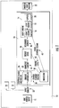
Figure 1 is a block diagram of an example notification appliance. -
Figure 2 is a block diagram of a portion of a controller of the notification appliance. -
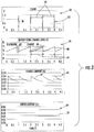
Figure 3 is a graph illustrating wave forms associated with components of the example notification appliance. -
Figure 4 is a block diagram of the example charge controller. - Referring to
Figure 1 , anexample notification appliance 10 includes alight engine 14 that generates a brief, intense flash of light at a predetermined interval. Theexample notification appliance 10 is one ofmany notification appliances 10 that are part of a notification appliance circuit (NAC) schematically shown at 12. Each of thenotification appliances 10 that are part of theNAC 12 are required to flash at the same time. However, it is not practical for all of theappliances 10 to take the amount of power required for a flash from theNAC power input 15 during the short time duration of each flash. Accordingly, eachnotification appliance 10 includes anenergy store 24 that buffers energy from theNAC power input 15 for thelight engine 14.Energy store 24 may include a super-capacitor, a capacitor or a battery, or other form of energy storage. - A
charge controller 26 includes acurrent controller 28 and aprocessor 30.Processor 30 controls flash timing for the flash, the timing corresponding to theinterval 54 shown inFigure 3 described below, by usingflash control 74 that generates aflash control signal 42 to control thelight driver 16. - The charging
current 34 is adjusted by theprocessor 30 that is part of thecharge controller 26. In order to control charge of theenergy store 24,processor 30 provides current control at chargecurrent control 38. Theprocessor 30 includes an algorithm that controls the chargingcurrent 34 which charges theenergy store 24. Theenergy store 24 is used to convert a long duration low power charge frominput current 32 provided by theNAC power input 15 into the high power short duration energy discharge utilized by thelight engine 14. Theenergy store 24 is charged with a chargingcurrent 34 to generate thedischarge current 36 to thelight engine 14. The charging current 34 must charge theenergy store 24 up to a fully charged level within a predetermined interval at which thelight engine 14 operates. Theenergy store 24 is charged from a low charge level to a fully charged level required to power thelight engine 14 and then recharged within the predefined interval of flashes for the next flash. - During the discharge period of the predefined interval, the
light engine 14 takes power from theenergy store 24 and uses alight driver 16 to convert that power into a form usable by alight source 18. Thelight source 18 generates light conditioned throughoptics 20 to emit a desiredlight pattern 22. - Each of the
notification appliances 10 have significant variability due to component variations due to manufacturing tolerances and also each may behave differently due to the effect of ambient temperature local to eachseparate notification appliance 10 expressed through thermal coefficients. For example, included within thenotification appliances 10 there arelight engine 14 components as well as electrical components and hardware that define connections and provide electrical connections and communication throughout each of theappliances 10. All of these components may vary between eachnotification appliance 10. The variability may affect the energy storage, charge, and discharge such that somenotification appliances 10 may consume more discharge current 36 to produce a sufficient minimumlight pattern 22, and others may take less. - Despite the variability between
various notification appliances 10 within theNAC 12, each of thelight engines 14 are required to flash at the same synchronized interval and produce a minimumlight pattern 22. Accordingly, the disclosedcharge controller 26 accommodates variability within components and environmental conditions for eachappliance 10 and provides sufficient charging current to theenergy store 24 within the predefined interval as discussed below. - The
example charge controller 26 includes aprocessor 30 which includes a control algorithm that adjusts the charging current 34 such that thecharge level 40 of theenergy store 24 is recharged to a full charge level required to generate the light flashes at a minimum output level and at an exact time that corresponds with the predetermined interval. - Referring to
Figures 2 and3 with continued reference toFigure 1 , thecharge level 40 is expressed inprocessor 30 as a signal which is input into feed forwardmodel 46 andadaptive feedback 48 described below. Thelight engine 14 generates the flash shown as theenergy discharge 52 indicated ongraph 50 at thepredetermined intervals 54. Note that the intervals shown ongraphs energy discharge 52 corresponds with thedischarge 60 shown in the energy storecharge level graph 56. A charge current 34 provided by thecurrent controller 28 of thecharge controller 26 provides energy to theenergy store 24 as is schematically shown ingraph 62. The input current 32 from theNAC 12 into theappliance 10 is illustrated bygraph 64. - The input current 32 is constant with a peak current to average current ratio that is between about 0.9 and 1.1. In another example embodiment a ratio between the peak current and average current is 1:1. Thus, for any given flash, the most optimal point is when the root mean square (RMS) current is equal to the average of the input current 32. The RMS current may be greater than the average current if the instantaneous current level falls below the average current for some period of a predetermined interval; this situation is considered sub-optimal.
- Note that at startup, the charge level of the device may be different due to thermal factors and the
energy store 24 being at a lower energy state than would be typical in a running system, sostartup manager 84 loads a charge level profile optimized to transition theenergy store 24 from a lower energy state to a running state. - When the system is in a running state, the constant input current 32 is possible due to the charge current 34 being controlled to charge the
energy store 24 to the required charge level using theentire interval 54 such that there is no plateau in the charge levels. Instead, each charge event proceeds from a low charge point to a fully charged point at a continually increasing rate to the fully charged point indicated at 58. In other words, thecurrent controller 28 supplies charging current 34 to theenergy store 24 such that theenergy store 24 attains a rate of charge to achieve thefull charge 58 at the end of the charging interval immediately prior to dischargeevents - As the
energy store 24 charges, the voltage increases, and to maintain constant power to theenergy store 24, the charge current 34 is decreased. Therefore as shown ingraphs energy store 24 and thecharge level 40 increases for the entire duration of theinterval 54 betweendischarges 52, and drops precipitously atdischarge event 60. Accordingly, theenergy store 24 is charged such that thecharge level 40 reaches the full charge indicated at 58 within thesame interval 54 and just before the energy is needed for eachdischarge event 52. - As described above, the charging current 34 is adjusted by the
processor 30 that is part of thecharge controller 26.Processor 30 includes algorithms such as a feed forwardmodel 46 and anadaptive feedback 48. - The feed forward
model 46 accepts as input acharge level profile 78 and environmental inputs (e.g. temperature 44) and generates a predicted input current 66 for the charging current 34 that assumes all components are operating within their nominal values. Thecharge level profile 78 is the optimal efficiency path to get from the energy store's present state (at the end of the discharge event 52) to the target charge level 80 (at the end of interval 54). The sample and hold 82 captures the charge state at the beginning and end of the previous discharge cycle as a reference for thecharge level profile 78. - The nominal values for each of the components along with information indicative of the surrounding
environment 44 are used to determine the predicted input current 66. Information indicative of the surrounding environment, may include, for example, temperature as is schematically indicated at 44, but may also include other information such as humidity or other environmental factors. Such environmental information, such astemperature information 44, is provided by sensors and gauges (not shown) communicative withprocessor 30. The predicted input current 66 is the current required to charge theenergy store 24 to the fully chargedpoint 58 from the dischargedlevel 60 within theinterval 54 with all components operating within nominal values. -
Adaptive feedback loop 48 may correct variation from any cause, but typically corrects variation caused by environmental factors and tolerance. Theadaptive feedback loop 48 accepts as inputs thecharge level profile 78 and theactual charge level 40 and generates acorrection value 68 that remedies variations in the charging rate of theenergy store 24 caused by detected variations from nominal values for the components of thenotification appliance 10 as described below. Note that theadaptive feedback loop 48 does not detect variations in component values directly, but rather detects departures between the ideal path "charge level profile" and the actual path "charge level". - Accordingly, the predicted input current 66 generated by the feed forward
model 46 are combined with thecorrection value 68 generated by theadaptive feedback loop 48 to generate a chargecurrent control 38 signal communicated to thecurrent controller 28 to control the charging current 34 to theenergy store 24. An effect of the chargecurrent control 38 on the charging current 34 is that the rate that the charging current 34 is applied to theenergy store 24 changes such that, despite variation caused by environmental factors and tolerance, thecharge level 40 achieves an expected value duringintervals 54 and just prior to dischargeevents 52. - Referring to
Figure 4 with continued reference toFigures 1 ,2 and3 , theexample charge controller 26 is shown schematically with the feed forwardmodel 46 and theadaptive feedback loop 48. The feed forwardmodel 46 may be run as part ofprocessor 30 or as part of a separate microprocessor connected toprocessor 30. The energystore charge level 40 as shown ingraph 56 is sensed by an analog-to-digital converter ADC 70. The chargecurrent control 38 is accomplished by a digital-to-analog converter DAC 72. Thefeedback loop 48 may be a proportional integral derivative PID controller or may be a proportional integral PI controller, or other employ another adaptive feedback methodology as is known in the art. - The example system adapts to component variations and environmental changes by adapting the
charge level profile 78 to replenish the charge level to the full charge as is indicated at 58 immediately prior to thelight discharge event 52. The rate of charge of theenergy store 24 is independent of any specific starting time and is determined based on the lowest charge level at any given interval and the amount of charge required and rate required to recharge theenergy store 24 to the full charge level within theinterval 54. The rate required to recharge theenergy store 24 at to the full charge level is determined by theprocessor 30 to take substantially theentire interval 54 such that thecharge level 40 is increasing up until the point offull charge 58 just prior to discharge 60. - As discussed above, the
charge controller 26 predicts the current level required to replenish theenergy store 24 utilizing the feed forwardmodel 46; the feed forwardmodel 46 predicts the required current levels to replenish theenergy store 24 based on nominal values for components of thenotification appliance 10. Accordingly, rather than directly controlling the input current 32, the charge current 34 is controlled. Because the charge current 34 is easier to control it simplifies and lowers costs for implementing the disclosed charging method. - As discussed above, the
adaptive feedback loop 48 corrects for variation in the components as well as environmental conditions to tailor the charge current 34 such that the charge current recharges theenergy store 24 to the full charge level within theinterval 54 betweendischarge events 52. Accordingly, the example adaptive charging method provides for the use of a constant input current enabling lower peak currents. This in turn enables for more notification appliances to be on a given circuit, and allows longer runs with lower cost wiring and lower quantity of power supplies. Moreover, the reduction in the use of energy throughout theNAC 12 allows for smaller capacity battery backups and enables other efficiencies and savings in materials. - Although an example embodiment has been disclosed, a worker of ordinary skill in this art would recognize that certain modifications would come within the scope of this disclosure. For that reason, the following claims should be studied to determine the scope and content of this disclosure.
Claims (15)
- A notification appliance comprising:a light engine for generating light flashes at a predetermined interval;an energy store for supplying energy to the light engine to generate the light flashes at the predetermined interval; anda charge controller for charging the energy store to a full charge level required to generate the light flashes, the charge controller controlling an input current to charge the energy store to reach the full charge level at the predetermined interval.
- The notification appliance as recited in claim 1, wherein the charge controller includes a feed forward model that determines a predicted input current required to recharge the energy store at the predetermined interval.
- The notification appliance as recited in claim 2, wherein the predicted input current is based on performance of components in the notification appliance operating within nominal values.
- The notification appliance as recited in claim 3, wherein the current controller includes an adaptive feedback loop that generates a correction value for adjusting the predicted input current based on deviations from the nominal values of the components of the notification appliance.
- The notification appliance as recited in claim 4,
wherein the adaptive feedback loop generates the correction value based on environmental conditions surrounding the notification appliance; and/or
wherein the charge controller includes an inverse model to set the input current to a constant value such that a ratio of a peak current to an average current is between about 0.9 and 1.1; and/or
wherein the charge controller includes an inverse model to set the input current to a constant value such that a ratio of a peak current to an average current is about 1:1. - The notification appliance as recited in any of the preceding claims,
wherein the energy storage device is discharged to a low charge level after generation of a light flash and charged from the low charge level to the full charge level at an increasing rate for substantially the entire predetermined interval; and/or
wherein the charge controller supplies a charging current according to a charge level profile determined to charge the energy store from a low charge point after the discharge cycle to the full charge level at the end of the predetermined interval. - The notification appliance as recited in any of the preceding claims, including a sample and hold that captures the charge state of the energy store at a beginning and end of a discharge cycle.
- The notification appliance as recited in any of the preceding claims, wherein the predetermined interval is between 0.9 and 1.1 seconds.
- An energy discharge device comprising:a discharge component generating a high energy event at a predetermined interval;an energy storage device for supplying energy to the discharge component to generate the high energy event at the predetermined interval; anda charge controller for charging the energy storage device to a full charge level required to generate the high energy event, the current controller controlling an input current to charge the energy store to reach the full charge level at the predetermined interval.
- The energy discharge device as recited in claim 9, wherein the charge controller includes a feed forward model that determines a predicted input current required to recharge the energy store at the predetermined interval.
- The energy discharge device as recited in claim 9 or 10,
wherein the predicted input current is based on performance of components in the energy discharge device operating within nominal values; and/or
wherein the charge controller includes an inverse model to set the input current to a constant value such that a ratio of a peak current to an average current is between about 0.9 and 1.1. - The energy discharge device as recited in claim 11, wherein the charge controller includes an adaptive feedback loop that generates a correction value for adjusting the predicted input current based on deviations from the nominal values of the components of the energy discharge device.
- The energy discharge device as recited in any of claims 9 to 12,
wherein the energy storage device is discharged to a low charge level after supply to the discharge component and charged from the low charge level to the full charge level at an increasing rate for the predetermined interval; and/or
wherein the energy discharge device includes a sample and hold that captures the charge state of the energy store at a beginning and end of a discharge cycle, wherein the charge controller supplies a charging current according to a charge level profile determined to charge the energy store from a low charge state after the discharge cycle to the full charge level at the end of the predetermined interval. - A method of charging an energy store of a notification appliance, the method comprising:determining a predicted input current required to recharge an energy store at a predetermined interval with a feed forward model of a current controller based on nominal operating values of components of the notification appliance;generating a correction value with an adaptive feedback loop of the current controller for adjusting the predicted input current based on deviations from the nominal values of the components of the notification appliance; andcharging the energy storage device to reach a full charge level at the predetermined interval.
- The method as recited in claim 14,
wherein the method includes setting an input current based on the corrected predicted input current to a constant value with a ratio of a peak current to an average current of about 0.9 and 1.1; and/or
wherein charging the energy storage device from a low charge level after a discharge includes charging at an increasing rate for substantially all of the predetermined interval.
Applications Claiming Priority (2)
| Application Number | Priority Date | Filing Date | Title |
|---|---|---|---|
| US201762608930P | 2017-12-21 | 2017-12-21 | |
| US201862618276P | 2018-01-17 | 2018-01-17 |
Publications (2)
| Publication Number | Publication Date |
|---|---|
| EP3503344A1 true EP3503344A1 (en) | 2019-06-26 |
| EP3503344B1 EP3503344B1 (en) | 2020-07-08 |
Family
ID=64744610
Family Applications (1)
| Application Number | Title | Priority Date | Filing Date |
|---|---|---|---|
| EP18213377.7A Active EP3503344B1 (en) | 2017-12-21 | 2018-12-18 | Optimized adaptive charging method for strobe |
Country Status (3)
| Country | Link |
|---|---|
| US (1) | US10916958B2 (en) |
| EP (1) | EP3503344B1 (en) |
| CA (1) | CA3028310C (en) |
Families Citing this family (1)
| Publication number | Priority date | Publication date | Assignee | Title |
|---|---|---|---|---|
| CA3101742A1 (en) * | 2018-06-01 | 2019-12-05 | Carrier Corporation | Power control for piezo sounder |
Citations (2)
| Publication number | Priority date | Publication date | Assignee | Title |
|---|---|---|---|---|
| US6087811A (en) * | 1998-12-09 | 2000-07-11 | Analog Modules, Inc. | Pulsed-output power supply with high power factor |
| US6822400B1 (en) * | 2001-01-23 | 2004-11-23 | Honeywell International, Inc. | Processor controlled strobe |
Family Cites Families (26)
| Publication number | Priority date | Publication date | Assignee | Title |
|---|---|---|---|---|
| JPS56109327A (en) | 1980-02-05 | 1981-08-29 | Nippon Kogaku Kk <Nikon> | Flash device with dimmer |
| JPS6059325A (en) | 1983-09-12 | 1985-04-05 | Fuji Photo Optical Co Ltd | Detecting circuit for strobe charging voltage |
| EP0272701B1 (en) | 1986-12-23 | 1993-04-21 | Asahi Kogaku Kogyo Kabushiki Kaisha | Apparatus for controlling charging of main capacitor of flash unit |
| US5341069A (en) | 1993-05-14 | 1994-08-23 | Wheelock Inc. | Microprocessor-controlled strobe light |
| US6160356A (en) | 1997-09-09 | 2000-12-12 | Olympus Optical Co., Ltd. | Strobo system used for camera |
| KR200194629Y1 (en) | 2000-03-23 | 2000-09-01 | 주식회사한림메카트로닉스 | Navigation strobo-light |
| KR100381046B1 (en) | 2000-03-31 | 2003-04-18 | 엘지.필립스 엘시디 주식회사 | Tape Carrier Package with Dummy Part and Liquid Crystal Display Apparatus |
| US6819059B2 (en) | 2002-10-25 | 2004-11-16 | Federal Signal Corporation | Flash strobe power supply system and method |
| US6856241B1 (en) | 2003-05-05 | 2005-02-15 | Honeywell International, Inc. | Variable candela strobe |
| US7242314B2 (en) | 2003-11-17 | 2007-07-10 | Honeywell International, Inc. | Strobe unit with current limiter |
| JP2006081321A (en) | 2004-09-09 | 2006-03-23 | Rohm Co Ltd | Capacitor charging apparatus, semiconductor integrated circuit therefor, and capacitor charging / discharging system |
| US7580234B2 (en) | 2005-01-20 | 2009-08-25 | Honeywell International Inc. | Single threshold current surge limiter circuit with disable function |
| US20070035255A1 (en) | 2005-08-09 | 2007-02-15 | James Shuster | LED strobe for hazard protection systems |
| JP2008070844A (en) | 2006-09-15 | 2008-03-27 | Ricoh Co Ltd | Imaging device |
| EP2009350A1 (en) | 2007-06-28 | 2008-12-31 | Siemens Schweiz AG | Strobe light for alarm systems |
| DE102007051793B4 (en) | 2007-10-30 | 2009-08-27 | Texas Instruments Deutschland Gmbh | LED driver with adaptive algorithm for storage capacitor precharge |
| US8653984B2 (en) | 2008-10-24 | 2014-02-18 | Ilumisys, Inc. | Integration of LED lighting control with emergency notification systems |
| GB2476292B (en) | 2009-12-18 | 2015-02-11 | Applied Concepts Ltd | Intruder deterrent systems |
| US9087441B2 (en) | 2011-12-02 | 2015-07-21 | Utc Fire & Security Corporation | Notification appliance circuit with energy storing notification devices |
| CN202535603U (en) | 2012-04-09 | 2012-11-14 | 安徽双科测控技术有限责任公司 | Intelligent traffic LED strobe and flash lamp |
| US8796931B2 (en) | 2012-06-18 | 2014-08-05 | Tyco Fire & Security Gmbh | Current regulated LED strobe drive circuit |
| JP2015138062A (en) | 2014-01-21 | 2015-07-30 | キヤノン株式会社 | LED strobe device |
| US9225249B2 (en) | 2014-01-28 | 2015-12-29 | Honeywell International Inc. | Power management alarm devices |
| CA2969450A1 (en) | 2014-12-02 | 2016-06-09 | Michael Waters | Light devices and control software |
| US9875624B2 (en) | 2016-02-23 | 2018-01-23 | Cooper Technologies Company | Notification device with non-uniform LED strobe light pulse shaping control and methods |
| US10447054B2 (en) | 2016-05-20 | 2019-10-15 | Robert Bosch Gmbh | Staircase charging |
-
2018
- 2018-12-17 US US16/222,142 patent/US10916958B2/en active Active
- 2018-12-18 EP EP18213377.7A patent/EP3503344B1/en active Active
- 2018-12-20 CA CA3028310A patent/CA3028310C/en active Active
Patent Citations (2)
| Publication number | Priority date | Publication date | Assignee | Title |
|---|---|---|---|---|
| US6087811A (en) * | 1998-12-09 | 2000-07-11 | Analog Modules, Inc. | Pulsed-output power supply with high power factor |
| US6822400B1 (en) * | 2001-01-23 | 2004-11-23 | Honeywell International, Inc. | Processor controlled strobe |
Also Published As
| Publication number | Publication date |
|---|---|
| US20190199102A1 (en) | 2019-06-27 |
| CA3028310C (en) | 2021-03-23 |
| CA3028310A1 (en) | 2019-06-21 |
| US10916958B2 (en) | 2021-02-09 |
| EP3503344B1 (en) | 2020-07-08 |
Similar Documents
| Publication | Publication Date | Title |
|---|---|---|
| CN100456906C (en) | Ballast for discharge lamps and method of operating discharge lamps with a DC-DC converter | |
| US8063581B2 (en) | Drive circuit for driving a load with pulsed current | |
| CN102907173B (en) | With with the LED manipulation portion of the constant-current source of clock signal duty | |
| US9487093B2 (en) | Control device for a DC-to-DC converter of an electrical drive system, and a method for operating a DC-to-DC converter | |
| US9673635B2 (en) | Self sustaining energy harvesting system | |
| US20040251852A1 (en) | Electronic ballast for a discharge lamp | |
| US10948934B1 (en) | Voltage regulator with piecewise linear loadlines | |
| CN108701996B (en) | Virtual inertia power supply supporting grid control | |
| JP2008257309A (en) | Step-up maximum power point tracking device and control method | |
| JP6008277B2 (en) | Solid state light source lighting device, lighting fixture, lighting system | |
| US6087811A (en) | Pulsed-output power supply with high power factor | |
| EP3785491A1 (en) | A driver arrangement for a led lighting device, a lighting device using the same and a drive method | |
| US10916958B2 (en) | Optimized adaptive charging method for strobe | |
| US6496344B1 (en) | Circuit for supplying a consumer with electric energy | |
| US10804826B2 (en) | Control device and control method for power generation system | |
| EP3540703B1 (en) | Single stage current controller for a notification appliance | |
| JP6786402B2 (en) | Demand control device and demand control method | |
| JP2019103209A (en) | Photovoltaic power generation system with solar cell module deterioration preventing function | |
| JP6613816B2 (en) | Lighting device and lighting apparatus | |
| AU2014265103A1 (en) | Control method for preventing auxiliary generator circuit of diesel locomotive from overvoltage | |
| JP6273885B2 (en) | LED power supply device and LED lighting device | |
| US20200359481A1 (en) | Operating circuit and method for operating at least one illuminant | |
| US10153693B2 (en) | DC-DC converter including dynamically adjusted duty cycle limit | |
| JP2013254606A (en) | Led power circuit and led lighting device using the same | |
| EP3592111A1 (en) | A driver arrangement for a led lighting device, a lighting device using the same and a drive method |
Legal Events
| Date | Code | Title | Description |
|---|---|---|---|
| PUAI | Public reference made under article 153(3) epc to a published international application that has entered the european phase |
Free format text: ORIGINAL CODE: 0009012 |
|
| STAA | Information on the status of an ep patent application or granted ep patent |
Free format text: STATUS: THE APPLICATION HAS BEEN PUBLISHED |
|
| AK | Designated contracting states |
Kind code of ref document: A1 Designated state(s): AL AT BE BG CH CY CZ DE DK EE ES FI FR GB GR HR HU IE IS IT LI LT LU LV MC MK MT NL NO PL PT RO RS SE SI SK SM TR |
|
| AX | Request for extension of the european patent |
Extension state: BA ME |
|
| STAA | Information on the status of an ep patent application or granted ep patent |
Free format text: STATUS: REQUEST FOR EXAMINATION WAS MADE |
|
| 17P | Request for examination filed |
Effective date: 20191220 |
|
| RBV | Designated contracting states (corrected) |
Designated state(s): AL AT BE BG CH CY CZ DE DK EE ES FI FR GB GR HR HU IE IS IT LI LT LU LV MC MK MT NL NO PL PT RO RS SE SI SK SM TR |
|
| GRAP | Despatch of communication of intention to grant a patent |
Free format text: ORIGINAL CODE: EPIDOSNIGR1 |
|
| STAA | Information on the status of an ep patent application or granted ep patent |
Free format text: STATUS: GRANT OF PATENT IS INTENDED |
|
| RIC1 | Information provided on ipc code assigned before grant |
Ipc: G08B 5/38 20060101ALN20200130BHEP Ipc: H02J 7/00 20060101AFI20200130BHEP Ipc: H05B 41/30 20060101ALI20200130BHEP Ipc: F21S 10/06 20060101ALI20200130BHEP Ipc: G08B 29/18 20060101ALI20200130BHEP |
|
| INTG | Intention to grant announced |
Effective date: 20200221 |
|
| GRAS | Grant fee paid |
Free format text: ORIGINAL CODE: EPIDOSNIGR3 |
|
| GRAA | (expected) grant |
Free format text: ORIGINAL CODE: 0009210 |
|
| STAA | Information on the status of an ep patent application or granted ep patent |
Free format text: STATUS: THE PATENT HAS BEEN GRANTED |
|
| AK | Designated contracting states |
Kind code of ref document: B1 Designated state(s): AL AT BE BG CH CY CZ DE DK EE ES FI FR GB GR HR HU IE IS IT LI LT LU LV MC MK MT NL NO PL PT RO RS SE SI SK SM TR |
|
| REG | Reference to a national code |
Ref country code: AT Ref legal event code: REF Ref document number: 1289508 Country of ref document: AT Kind code of ref document: T Effective date: 20200715 Ref country code: CH Ref legal event code: EP |
|
| REG | Reference to a national code |
Ref country code: DE Ref legal event code: R096 Ref document number: 602018005903 Country of ref document: DE |
|
| REG | Reference to a national code |
Ref country code: IE Ref legal event code: FG4D |
|
| REG | Reference to a national code |
Ref country code: LT Ref legal event code: MG4D |
|
| REG | Reference to a national code |
Ref country code: AT Ref legal event code: MK05 Ref document number: 1289508 Country of ref document: AT Kind code of ref document: T Effective date: 20200708 |
|
| REG | Reference to a national code |
Ref country code: NL Ref legal event code: MP Effective date: 20200708 |
|
| PG25 | Lapsed in a contracting state [announced via postgrant information from national office to epo] |
Ref country code: LT Free format text: LAPSE BECAUSE OF FAILURE TO SUBMIT A TRANSLATION OF THE DESCRIPTION OR TO PAY THE FEE WITHIN THE PRESCRIBED TIME-LIMIT Effective date: 20200708 Ref country code: HR Free format text: LAPSE BECAUSE OF FAILURE TO SUBMIT A TRANSLATION OF THE DESCRIPTION OR TO PAY THE FEE WITHIN THE PRESCRIBED TIME-LIMIT Effective date: 20200708 Ref country code: SE Free format text: LAPSE BECAUSE OF FAILURE TO SUBMIT A TRANSLATION OF THE DESCRIPTION OR TO PAY THE FEE WITHIN THE PRESCRIBED TIME-LIMIT Effective date: 20200708 Ref country code: BG Free format text: LAPSE BECAUSE OF FAILURE TO SUBMIT A TRANSLATION OF THE DESCRIPTION OR TO PAY THE FEE WITHIN THE PRESCRIBED TIME-LIMIT Effective date: 20201008 Ref country code: ES Free format text: LAPSE BECAUSE OF FAILURE TO SUBMIT A TRANSLATION OF THE DESCRIPTION OR TO PAY THE FEE WITHIN THE PRESCRIBED TIME-LIMIT Effective date: 20200708 Ref country code: GR Free format text: LAPSE BECAUSE OF FAILURE TO SUBMIT A TRANSLATION OF THE DESCRIPTION OR TO PAY THE FEE WITHIN THE PRESCRIBED TIME-LIMIT Effective date: 20201009 Ref country code: NO Free format text: LAPSE BECAUSE OF FAILURE TO SUBMIT A TRANSLATION OF THE DESCRIPTION OR TO PAY THE FEE WITHIN THE PRESCRIBED TIME-LIMIT Effective date: 20201008 Ref country code: AT Free format text: LAPSE BECAUSE OF FAILURE TO SUBMIT A TRANSLATION OF THE DESCRIPTION OR TO PAY THE FEE WITHIN THE PRESCRIBED TIME-LIMIT Effective date: 20200708 Ref country code: PT Free format text: LAPSE BECAUSE OF FAILURE TO SUBMIT A TRANSLATION OF THE DESCRIPTION OR TO PAY THE FEE WITHIN THE PRESCRIBED TIME-LIMIT Effective date: 20201109 Ref country code: FI Free format text: LAPSE BECAUSE OF FAILURE TO SUBMIT A TRANSLATION OF THE DESCRIPTION OR TO PAY THE FEE WITHIN THE PRESCRIBED TIME-LIMIT Effective date: 20200708 |
|
| PG25 | Lapsed in a contracting state [announced via postgrant information from national office to epo] |
Ref country code: IS Free format text: LAPSE BECAUSE OF FAILURE TO SUBMIT A TRANSLATION OF THE DESCRIPTION OR TO PAY THE FEE WITHIN THE PRESCRIBED TIME-LIMIT Effective date: 20201108 Ref country code: LV Free format text: LAPSE BECAUSE OF FAILURE TO SUBMIT A TRANSLATION OF THE DESCRIPTION OR TO PAY THE FEE WITHIN THE PRESCRIBED TIME-LIMIT Effective date: 20200708 Ref country code: RS Free format text: LAPSE BECAUSE OF FAILURE TO SUBMIT A TRANSLATION OF THE DESCRIPTION OR TO PAY THE FEE WITHIN THE PRESCRIBED TIME-LIMIT Effective date: 20200708 Ref country code: PL Free format text: LAPSE BECAUSE OF FAILURE TO SUBMIT A TRANSLATION OF THE DESCRIPTION OR TO PAY THE FEE WITHIN THE PRESCRIBED TIME-LIMIT Effective date: 20200708 |
|
| PG25 | Lapsed in a contracting state [announced via postgrant information from national office to epo] |
Ref country code: NL Free format text: LAPSE BECAUSE OF FAILURE TO SUBMIT A TRANSLATION OF THE DESCRIPTION OR TO PAY THE FEE WITHIN THE PRESCRIBED TIME-LIMIT Effective date: 20200708 |
|
| REG | Reference to a national code |
Ref country code: DE Ref legal event code: R097 Ref document number: 602018005903 Country of ref document: DE |
|
| PG25 | Lapsed in a contracting state [announced via postgrant information from national office to epo] |
Ref country code: IT Free format text: LAPSE BECAUSE OF FAILURE TO SUBMIT A TRANSLATION OF THE DESCRIPTION OR TO PAY THE FEE WITHIN THE PRESCRIBED TIME-LIMIT Effective date: 20200708 Ref country code: SM Free format text: LAPSE BECAUSE OF FAILURE TO SUBMIT A TRANSLATION OF THE DESCRIPTION OR TO PAY THE FEE WITHIN THE PRESCRIBED TIME-LIMIT Effective date: 20200708 Ref country code: EE Free format text: LAPSE BECAUSE OF FAILURE TO SUBMIT A TRANSLATION OF THE DESCRIPTION OR TO PAY THE FEE WITHIN THE PRESCRIBED TIME-LIMIT Effective date: 20200708 Ref country code: CZ Free format text: LAPSE BECAUSE OF FAILURE TO SUBMIT A TRANSLATION OF THE DESCRIPTION OR TO PAY THE FEE WITHIN THE PRESCRIBED TIME-LIMIT Effective date: 20200708 Ref country code: DK Free format text: LAPSE BECAUSE OF FAILURE TO SUBMIT A TRANSLATION OF THE DESCRIPTION OR TO PAY THE FEE WITHIN THE PRESCRIBED TIME-LIMIT Effective date: 20200708 Ref country code: RO Free format text: LAPSE BECAUSE OF FAILURE TO SUBMIT A TRANSLATION OF THE DESCRIPTION OR TO PAY THE FEE WITHIN THE PRESCRIBED TIME-LIMIT Effective date: 20200708 |
|
| PLBE | No opposition filed within time limit |
Free format text: ORIGINAL CODE: 0009261 |
|
| STAA | Information on the status of an ep patent application or granted ep patent |
Free format text: STATUS: NO OPPOSITION FILED WITHIN TIME LIMIT |
|
| PG25 | Lapsed in a contracting state [announced via postgrant information from national office to epo] |
Ref country code: AL Free format text: LAPSE BECAUSE OF FAILURE TO SUBMIT A TRANSLATION OF THE DESCRIPTION OR TO PAY THE FEE WITHIN THE PRESCRIBED TIME-LIMIT Effective date: 20200708 |
|
| 26N | No opposition filed |
Effective date: 20210409 |
|
| PG25 | Lapsed in a contracting state [announced via postgrant information from national office to epo] |
Ref country code: SK Free format text: LAPSE BECAUSE OF FAILURE TO SUBMIT A TRANSLATION OF THE DESCRIPTION OR TO PAY THE FEE WITHIN THE PRESCRIBED TIME-LIMIT Effective date: 20200708 |
|
| REG | Reference to a national code |
Ref country code: DE Ref legal event code: R119 Ref document number: 602018005903 Country of ref document: DE |
|
| PG25 | Lapsed in a contracting state [announced via postgrant information from national office to epo] |
Ref country code: SI Free format text: LAPSE BECAUSE OF FAILURE TO SUBMIT A TRANSLATION OF THE DESCRIPTION OR TO PAY THE FEE WITHIN THE PRESCRIBED TIME-LIMIT Effective date: 20200708 Ref country code: MC Free format text: LAPSE BECAUSE OF FAILURE TO SUBMIT A TRANSLATION OF THE DESCRIPTION OR TO PAY THE FEE WITHIN THE PRESCRIBED TIME-LIMIT Effective date: 20200708 |
|
| REG | Reference to a national code |
Ref country code: BE Ref legal event code: MM Effective date: 20201231 |
|
| PG25 | Lapsed in a contracting state [announced via postgrant information from national office to epo] |
Ref country code: LU Free format text: LAPSE BECAUSE OF NON-PAYMENT OF DUE FEES Effective date: 20201218 Ref country code: IE Free format text: LAPSE BECAUSE OF NON-PAYMENT OF DUE FEES Effective date: 20201218 Ref country code: FR Free format text: LAPSE BECAUSE OF NON-PAYMENT OF DUE FEES Effective date: 20201231 |
|
| PG25 | Lapsed in a contracting state [announced via postgrant information from national office to epo] |
Ref country code: DE Free format text: LAPSE BECAUSE OF NON-PAYMENT OF DUE FEES Effective date: 20210701 |
|
| PG25 | Lapsed in a contracting state [announced via postgrant information from national office to epo] |
Ref country code: TR Free format text: LAPSE BECAUSE OF FAILURE TO SUBMIT A TRANSLATION OF THE DESCRIPTION OR TO PAY THE FEE WITHIN THE PRESCRIBED TIME-LIMIT Effective date: 20200708 Ref country code: MT Free format text: LAPSE BECAUSE OF FAILURE TO SUBMIT A TRANSLATION OF THE DESCRIPTION OR TO PAY THE FEE WITHIN THE PRESCRIBED TIME-LIMIT Effective date: 20200708 Ref country code: CY Free format text: LAPSE BECAUSE OF FAILURE TO SUBMIT A TRANSLATION OF THE DESCRIPTION OR TO PAY THE FEE WITHIN THE PRESCRIBED TIME-LIMIT Effective date: 20200708 |
|
| PG25 | Lapsed in a contracting state [announced via postgrant information from national office to epo] |
Ref country code: MK Free format text: LAPSE BECAUSE OF FAILURE TO SUBMIT A TRANSLATION OF THE DESCRIPTION OR TO PAY THE FEE WITHIN THE PRESCRIBED TIME-LIMIT Effective date: 20200708 |
|
| PG25 | Lapsed in a contracting state [announced via postgrant information from national office to epo] |
Ref country code: BE Free format text: LAPSE BECAUSE OF NON-PAYMENT OF DUE FEES Effective date: 20201231 |
|
| REG | Reference to a national code |
Ref country code: CH Ref legal event code: PL |
|
| PG25 | Lapsed in a contracting state [announced via postgrant information from national office to epo] |
Ref country code: LI Free format text: LAPSE BECAUSE OF NON-PAYMENT OF DUE FEES Effective date: 20211231 Ref country code: CH Free format text: LAPSE BECAUSE OF NON-PAYMENT OF DUE FEES Effective date: 20211231 |
|
| P01 | Opt-out of the competence of the unified patent court (upc) registered |
Effective date: 20230527 |
|
| PGFP | Annual fee paid to national office [announced via postgrant information from national office to epo] |
Ref country code: GB Payment date: 20251120 Year of fee payment: 8 |