EP3503330A1 - Dynamic motor current phase unbalance protection - Google Patents
Dynamic motor current phase unbalance protection Download PDFInfo
- Publication number
- EP3503330A1 EP3503330A1 EP18209568.7A EP18209568A EP3503330A1 EP 3503330 A1 EP3503330 A1 EP 3503330A1 EP 18209568 A EP18209568 A EP 18209568A EP 3503330 A1 EP3503330 A1 EP 3503330A1
- Authority
- EP
- European Patent Office
- Prior art keywords
- current
- motor
- flc
- iavg
- full load
- Prior art date
- Legal status (The legal status is an assumption and is not a legal conclusion. Google has not performed a legal analysis and makes no representation as to the accuracy of the status listed.)
- Granted
Links
Images




Classifications
-
- H—ELECTRICITY
- H02—GENERATION; CONVERSION OR DISTRIBUTION OF ELECTRIC POWER
- H02H—EMERGENCY PROTECTIVE CIRCUIT ARRANGEMENTS
- H02H3/00—Emergency protective circuit arrangements for automatic disconnection directly responsive to an undesired change from normal electric working condition with or without subsequent reconnection ; integrated protection
- H02H3/006—Calibration or setting of parameters
-
- H—ELECTRICITY
- H02—GENERATION; CONVERSION OR DISTRIBUTION OF ELECTRIC POWER
- H02H—EMERGENCY PROTECTIVE CIRCUIT ARRANGEMENTS
- H02H7/00—Emergency protective circuit arrangements specially adapted for specific types of electric machines or apparatus or for sectionalised protection of cable or line systems, and effecting automatic switching in the event of an undesired change from normal working conditions
- H02H7/08—Emergency protective circuit arrangements specially adapted for specific types of electric machines or apparatus or for sectionalised protection of cable or line systems, and effecting automatic switching in the event of an undesired change from normal working conditions for dynamo-electric motors
-
- H—ELECTRICITY
- H02—GENERATION; CONVERSION OR DISTRIBUTION OF ELECTRIC POWER
- H02H—EMERGENCY PROTECTIVE CIRCUIT ARRANGEMENTS
- H02H7/00—Emergency protective circuit arrangements specially adapted for specific types of electric machines or apparatus or for sectionalised protection of cable or line systems, and effecting automatic switching in the event of an undesired change from normal working conditions
- H02H7/08—Emergency protective circuit arrangements specially adapted for specific types of electric machines or apparatus or for sectionalised protection of cable or line systems, and effecting automatic switching in the event of an undesired change from normal working conditions for dynamo-electric motors
- H02H7/09—Emergency protective circuit arrangements specially adapted for specific types of electric machines or apparatus or for sectionalised protection of cable or line systems, and effecting automatic switching in the event of an undesired change from normal working conditions for dynamo-electric motors against over-voltage; against reduction of voltage; against phase interruption
Definitions
- a low cost means achieves a variable unbalance trip threshold, resulting in increased motor run time over that available from the known art unbalance trip means that uses a fixed point unbalance threshold.
- Three-phase induction motors have three windings in the stator, which when connected to power lines supplying alternating voltage and current in three-phases, cause magnetic flux to rotate in a positive sequence direction within the stator.
- the rotor within the stator has an arrangement of closed-loop coils that can rotate and have current induced in them by the rotating magnetic field of the stator windings, forcing the rotor to rotate in the same direction as the positive sequence direction of the magnetic flux within the stator.
- a three-phase motor may continue to operate with unbalanced voltages and currents, however its efficiency is reduced by both increased current and increased resistance due to heating.
- the stator winding with the highest current will have the greatest overheating, resulting in deterioration of the insulation of the stator winding.
- currents flow through the stator windings in a negative sequence direction, resulting in induction of negative sequence voltage in the rotor coils, abnormal current flow, and overheating.
- phase unbalance detection circuits for three-phase motors may be represented by U.S. Patent 5,243,489 , which discloses a plurality of operational amplifiers connected to current transformers in the three-phases, to provide a trip signal output when a phase unbalance is detected.
- the operational amplifiers determine whether there is any difference between pairs of voltage phases that is greater than a threshold value K.
- the threshold value K is a constant whose value may be manually set over a range of operating conditions.
- a problem with the state of the art is that a three-phase motor operating under a light load, may be able to tolerate a greater degree of current phase unbalance without overheating, than it would when operating under a heavier load.
- existing motor overload relays are unable to extend the run time of three-phase motors while operating under a light load, which are otherwise able to tolerate a greater degree of current phase unbalance.
- Existing motor overload relays are prone to nuisance tripping on unbalance when lightly loaded, causing unnecessary shutdowns when the motor is not actually at risk of overheating.
- an overload relay for a three-phase induction motor provides a low cost means to achieve a variable unbalance trip/time threshold, resulting in increased motor run time over that available from the known art unbalance trip relays that use a fixed point unbalance threshold.
- Each type of three-phase motor has a characteristic heating model, which relates the operating temperature of its core due to the ratio of the average current (I avg ) to rated full load current of the motor (FLC), i.e., the motor load. Heat generated by unbalanced phase currents adds to heat generated by the average current (I avg ) to raise the operating temperature of the core.
- the time interval necessary to raise the temperature of the core to the maximum operating temperature is the trip time after the initial detection of the condition of current phase unbalance.
- an adjusted threshold for detecting current phase unbalance is dynamically determined as a function of the ratio of the average of the currents to the rated full load current of the motor. The determination is based on the heating model of the motor. As the motor load decreases, the adjusted current phase unbalance threshold is increased, causing the resulting trip time to increase, thereby increasing motor run time and reducing downtime.
- the adjusted current phase unbalance threshold is decreased, causing the resulting trip time to decrease, thereby preventing the temperature of the core to rise to its maximum operating temperature, to avoid permanent damage to the motor.
- a plurality of current transformers associated with the overload relay connect with corresponding phases of a three-phase power system providing power to a three-phase motor.
- Each current transformer provides a value representative of current flow it senses through each corresponding phase of the three-phase power system.
- a memory in the overload relay is configured to store a cross-over point of average current (Iavg) to motor full load current (FLC) and a slope of a heating model curve of percent current phase unbalance vs. the ratio of average current (Iavg) to motor full load current (FLC), at the cross-over point of average current (Iavg) to motor full load current (FLC).
- a processor in the overload relay coupled to the memory and the plurality of current transformers, is configured to determine an adjusted threshold for a detected current phase unbalance at which the relay will be tripped, as a function of the ratio of average current (Iavg) to motor full load current (FLC), based on the cross-over point of average current (Iavg) to motor full load current (FLC) and the slope of a heating model curve of percent current phase unbalance vs. the ratio of average current (Iavg) to motor full load current (FLC), wherein as the motor load decreases, the adjusted current phase unbalance threshold is increased, thereby increasing motor run time and reducing downtime.
- a method for operating an overload relay for a three-phase induction motor comprises:
- an adjusted threshold for detected current phase unbalance is dynamically determined at which the relay is tripped.
- the adjusted threshold is a function of a ratio of an average of currents in the three-phases to the rated full load current of the motor, i.e., motor load.
- the adjusted current phase unbalance threshold is increased, causing the resulting trip time to increase, thereby increasing motor run time and reducing downtime.
- FIG. 1 is an example functional block diagram of the motor overload relay 100, in accordance with an example embodiment of the invention.
- the relay 100 conducts three-phase currents ⁇ 1, ⁇ 2, and ⁇ 3, through switches S1, S2, and S3 to the power input nodes N1, N2, and N3 of the three-phase motor 102.
- the stator windings W1, W2, and W3 are respectively connected between the power input nodes N1, N2, and N3 and neutral in the star or wye configuration.
- the rotor within the stator is driven into rotation when the switches S1, S2, and S3 are closed, delivering three-phase currents ⁇ 1, ⁇ 2, and ⁇ 3, to the stator windings W1, W2, and W3.
- the trip actuator 130 controls the on/off state of the switches S1, S2, and S3.
- the current transformers CT1, CT2, and CT3 associated with the overload relay 100 are inductively coupled to the currents ⁇ 1, ⁇ 2, and ⁇ 3, and output a sensing current I1, 12, and I3 to respective DC bridges B1, B2, and B3.
- the DC bridges B1, B2, and B3 output voltage signals V(I1), V(I2), and V(I3), to a microprocessor 110 and memory 112 in the overload relay.
- the current transformers CT1, CT2, and CT3 may be located inside the housing of the relay or they may be located outside of it.
- the memory 112 stores parameter calculation step 120, threshold adjustment step 122, calculate % unbalance step 124, and time-duration step 126, which are executed by the microprocessor 110.
- a settings register 128 provides overload protection settings to the microprocessor 110.
- An alarm unit 140 receives alarm signals from the microprocessor 110.
- the microprocessor 110 outputs control signals to the trip actuator 130.
- the invention operates by taking as input the level of motor load, represented by average current (I avg ) relative to the motor full load current (FLC) setting. This is used to adjust for the availability of motor capacity due to unbalance based on heating contribution from motor loading.
- I avg average current
- FLC motor full load current
- a conventional time-duration step 126 may be used for the current phase unbalance protection, with a dynamic threshold used for evaluation of the presence or absence of a current phase unbalance condition. As motor load increases, the current phase unbalance threshold is decreased and as motor load decreases the current phase unbalance threshold is increased.
- Figure 2 is an example flow diagram of an example overall process, including a parameter calculation step 120 and an adjusted threshold step 122.
- the determination of an adjusted threshold 122 varies a threshold value of current phase unbalance at which the motor overload relay 100 will be tripped.
- the settings 128 provides overload protection parameters, such as motor full load current (FLC), nominal current phase unbalance threshold, and unbalance trip time, the settings being provided to the parameter calculation step 120, shown in greater detail in Figure 4 .
- the current measurement 202 provides input to the threshold adjustment step 122, shown in greater detail in Figure 5 .
- Conventional time-duration step 126 is shown in greater detail in Figure 3 . It includes a I% unbalanced > threshold decision 210, a conventional Finite Impulse Response (FIR) / Infinite Impulse Response (IIR) filter 212, and an unbalance detection output 214.
- FIR Finite Impulse Response
- IIR Infinite Impulse Response
- the invention does not require additional parameters to be entered by the user beyond the overload protection parameters nominally used in the state of the art settings for the motor full load current, the current phase unbalance threshold and current phase unbalance trip time.
- the invention uses a novel process with two parts.
- the first part parameter calculation of Figure 4
- the second part current phase unbalance threshold adjustment of Figure 5
- the invention uses conventional current measurement and current phase unbalance calculation, known in the state of the art.
- Ii1 (I L1 - lavg I x 100) / lavg Imbalance ratio of current in phase 2 (in %)
- Ii2 (I L2 - lavg I x 100) / lavg Imbalance ratio of current in phase 3 (in %)
- Figure 3 is an example logic block diagram for generating a warning signal or a fault signal in response to the adjusted threshold 305 or 307 for a detected current phase unbalance at which the motor overload relay 100 will be tripped.
- the invention also uses a conventional time-duration step 126 for the current phase unbalance detection, with dynamic input from the step 126 to calculate an adjusted current phase unbalance threshold 305 or 307.
- Time-duration steps 126 are known in the art.
- phase sensing currents I1, 12, and I3 are input to block 302 to detect a current unbalance ratio limb for three-phase.
- the current phase unbalance ratio limb is compared with adjusted current phase balance threshold 305, which is a warning threshold Is1. If the current phase unbalance ratio limb is greater than the adjusted current phase balance threshold 305 Is1, then a current phase unbalance warning is output to the alarm 140 of Figure 1 .
- the current phase unbalance ratio limb is compared with adjusted current phase balance threshold 307, which is a fault threshold Is2. If the current phase unbalance ratio limb is greater than the adjusted current phase balance threshold 307 Is2, then outputs are sent to the AND gates 310 and 312.
- the start state 308 input to the AND gate 310 and the run state input to the AND gate 312 are signals generated by the current measurement block 202 of Figure 2 .
- the output of the AND gate 310 goes to the fault time out starting 314, which after the timeout T1, signals a current phase unbalance fault for motor starting.
- the output of the AND gate 312 goes to the fault time out starting 316, which after the timeout T2, signals a current phase unbalance fault for motor running.
- the fault timeouts T1 and T2 delay the trip action to minimize nuisance trips.
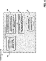
- Figure 4 is an example flow diagram of an example of the parameter calculation process 120 of Figure 2 , which is performed when the input settings are changed.
- Step 402 provides overload protection settings (FLC, trip class), and current phase unbalance protection settings (threshold, trip time).
- FLC overload protection settings
- Threshold current phase unbalance protection settings
- the thermal curve (trip time), which includes compensation for current unbalance, is calculated as a function of Iavg/FLC.
- the parameter Icross-over is calculated as the current where the trip time equals the unbalance protection trip time setting value.
- Step 406 performs the calculation ⁇ M cross-over ⁇ : slope of ideal heating model at Icross-over: ( ⁇ %unbalance / ⁇ Iavg/FLC), as shown in Figure 7 .
- the heating model is calculated as a function of Iavg/FLC and a fixed trip time (equal to the unbalance protection threshold setting) and expressed as current unbalance. In other words, the amount of unbalance to achieve the fixed trip time is calculated as a function of the motor load current.
- This calculation of the heating model is used to determine the slope of the model ⁇ ⁇ current unbalance ⁇ / ⁇ Iavg / FLC ⁇ .
- Step 408 performs current phase unbalance threshold adjustment parameters (M cross-over , I cross-over ), as shown in Figure 8 .
- M cross-over current phase unbalance threshold adjustment parameters
- I cross-over current phase unbalance threshold adjustment parameters
- the invention makes a simplifying assumption, for example in step 406, calculate ⁇ M cross-over ⁇ , by using a linear model of the relationship between current unbalance and Iavg/FLC. Because the curve of unbalance to reach a given fixed trip time is monotonic, the assumption reasonably ensures that the adjusted current unbalance threshold calculation will not yield an under-protection of the motor.
- FIG. 5 is an example flow diagram of an example process for the current phase unbalance threshold adjustment 122 of Figure 2 , which calculates the adjusted current phase unbalance threshold while the motor is running, based on current measurement input updates.
- Step 502 provides the current measurement to decision Step 506.
- Step 504 provides current phase unbalance threshold adjustment parameters (M cross-over , I cross-over ) to decision Step 506.
- Figure 6 is an example graph illustrating part of the parameter calculation process of Figure 4 .
- the graph has as the abscissa the ratio of the average of the currents in the three-phases (I avg ) to the rated full load current of the motor (FLC), i.e., the motor load.
- the graph has as the ordinate the trip time.
- the parameter I cross-over is calculated as the current where the trip time equals the fixed value unbalance protection trip time setting.
- the thermal curve (trip time), including compensation for current phase unbalance is calculated as a function of I avg /FLC.
- the parameter I cross-over is calculated as the current where the trip time equals the unbalance protection trip time setting value.
- FIG 7 is an example graph illustrating another part of the parameter calculation process of Figure 4 .
- the graph has as the abscissa the ratio of the average of the currents in the three-phases (I avg ) to the rated full load current of the motor (FLC).
- the graph has as the ordinate the current phase unbalance.
- the heating model line is calculated as a function of the ratio I avg /FLC and a fixed trip time (corresponding to the fixed value unbalance protection threshold setting) and expressed as current phase unbalance. This calculation of the heating model line is used to determine the slope M of the heating model line ⁇ current phase unbalance ⁇ / ⁇ I avg / FLC ⁇ . In other words, the amount of unbalance to achieve the fixed trip time is calculated as a function of the motor load current.
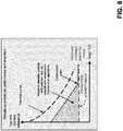
- Figure 8 is an example graph illustrating the current phase unbalance threshold adjustment calculation process of Figure 5 .
- the graph has as the abscissa the ratio of the average of the currents in the three-phases (I avg ) to the rated full load current of the motor (FLC).
- the graph has two variables as the ordinate.
- the first ordinate variable is trip time for the thermal curve line shown in the graph.
- the second ordinate variable is current phase balance for the region of operation enabled by the invention, as shown in the graph.
- the diagram shows the current phase unbalance trip characteristic achieved by executing the steps described above.
- an additional output may be provided by the function.
- the output may be a warning or information provided to the user by alarm 140 of Figure 1 , or it could be an additional protection function providing a trip to stop the motor operation.
- the output is provided when the result of the comparison, I avg > I cross-over , is "yes". The output would indicate that the motor is operating in an area of relatively high load concurrent with relatively high unbalance.
- the invention uses a novel process with two parts, but rather than adjusting the current phase unbalance threshold, the current phase unbalance trip time is adjusted.
- Overall similar algorithm steps are used (parameter calculation, protection adjustment based on measurement), however the adjustment is performed on a different characteristic of the protection function, i.e., the trip time. This is accomplished by repeating the steps of the above paragraphs [0041] through [0048], while replacing the ordinate of current phase unbalance with an ordinate of trip time, particularly in steps 406 and 408.
- the resulting invention provides an overload relay for a three-phase induction motor featuring a low cost means to achieve a variable unbalance trip threshold, resulting in increased motor run time over that available from the known art unbalance trip relays that use a fixed point unbalance threshold.
Landscapes
- Protection Of Generators And Motors (AREA)
- Control Of Electric Motors In General (AREA)
- Control Of Ac Motors In General (AREA)
Abstract
Description
- In a motor overload relay, a low cost means achieves a variable unbalance trip threshold, resulting in increased motor run time over that available from the known art unbalance trip means that uses a fixed point unbalance threshold.
- Three-phase induction motors have three windings in the stator, which when connected to power lines supplying alternating voltage and current in three-phases, cause magnetic flux to rotate in a positive sequence direction within the stator. The rotor within the stator has an arrangement of closed-loop coils that can rotate and have current induced in them by the rotating magnetic field of the stator windings, forcing the rotor to rotate in the same direction as the positive sequence direction of the magnetic flux within the stator.
- As long as the power supply voltages and currents are equal in magnitude in the three-phases, i.e. balanced, the magnetic flux rotates in the positive sequence direction within the stator. However, voltages and currents may occasionally become unbalanced in the three-phases of the power supply lines, for example due to faults in a distribution transformer or unbalanced distribution of single phase loads on the same branch circuit, such as a momentary current draw by starting-up large electrical machinery or by a heavy arc welder.
- A three-phase motor may continue to operate with unbalanced voltages and currents, however its efficiency is reduced by both increased current and increased resistance due to heating. The stator winding with the highest current will have the greatest overheating, resulting in deterioration of the insulation of the stator winding. During power supply unbalance, currents flow through the stator windings in a negative sequence direction, resulting in induction of negative sequence voltage in the rotor coils, abnormal current flow, and overheating.
- Under conditions of balanced voltages and currents, where the motor operates at a continuous load for a sufficient time, its operating temperature reaches thermal equilibrium. Each motor has a characteristic safe maximum operating temperature permitted by the motor design, above which permanent damage may begin to occur to insulating layers and other components. Under conditions of current phase unbalance, the stator windings generate heat at an increased rate causing a faster rise in the temperature of the surrounding core. The time interval necessary to raise the temperature of the core to the maximum operating temperature is the trip time after the detection of the unbalance condition. To avoid permanent damage to the motor, prior art overload relays set a fixed threshold for detected current phase unbalance at which the relay is prematurely tripped at an interval that is shorter than the trip time.
- The state of the art in phase unbalance detection circuits for three-phase motors may be represented by
U.S. Patent 5,243,489 , which discloses a plurality of operational amplifiers connected to current transformers in the three-phases, to provide a trip signal output when a phase unbalance is detected. The operational amplifiers determine whether there is any difference between pairs of voltage phases that is greater than a threshold value K. The threshold value K is a constant whose value may be manually set over a range of operating conditions. - A problem with the state of the art is that a three-phase motor operating under a light load, may be able to tolerate a greater degree of current phase unbalance without overheating, than it would when operating under a heavier load. However, existing motor overload relays are unable to extend the run time of three-phase motors while operating under a light load, which are otherwise able to tolerate a greater degree of current phase unbalance. Existing motor overload relays are prone to nuisance tripping on unbalance when lightly loaded, causing unnecessary shutdowns when the motor is not actually at risk of overheating.
- What is needed is a motor overload relay that provides a low cost means to achieve a variable unbalance trip/time threshold, resulting in increased motor run time over that available from the known art unbalance trip relays that use a fixed point unbalance threshold.
- In accordance with an example embodiment of the invention, an overload relay for a three-phase induction motor provides a low cost means to achieve a variable unbalance trip/time threshold, resulting in increased motor run time over that available from the known art unbalance trip relays that use a fixed point unbalance threshold.
- Each type of three-phase motor has a characteristic heating model, which relates the operating temperature of its core due to the ratio of the average current (Iavg) to rated full load current of the motor (FLC), i.e., the motor load. Heat generated by unbalanced phase currents adds to heat generated by the average current (Iavg) to raise the operating temperature of the core. The time interval necessary to raise the temperature of the core to the maximum operating temperature is the trip time after the initial detection of the condition of current phase unbalance.
- In accordance with an example embodiment of the invention, an adjusted threshold for detecting current phase unbalance is dynamically determined as a function of the ratio of the average of the currents to the rated full load current of the motor. The determination is based on the heating model of the motor. As the motor load decreases, the adjusted current phase unbalance threshold is increased, causing the resulting trip time to increase, thereby increasing motor run time and reducing downtime.
- Alternately, as the motor load increases, the adjusted current phase unbalance threshold is decreased, causing the resulting trip time to decrease, thereby preventing the temperature of the core to rise to its maximum operating temperature, to avoid permanent damage to the motor.
- In an example embodiment of the invention, a plurality of current transformers associated with the overload relay, connect with corresponding phases of a three-phase power system providing power to a three-phase motor. Each current transformer provides a value representative of current flow it senses through each corresponding phase of the three-phase power system.
- A memory in the overload relay, is configured to store a cross-over point of average current (Iavg) to motor full load current (FLC) and a slope of a heating model curve of percent current phase unbalance vs. the ratio of average current (Iavg) to motor full load current (FLC), at the cross-over point of average current (Iavg) to motor full load current (FLC).
- A processor in the overload relay, coupled to the memory and the plurality of current transformers, is configured to determine an adjusted threshold for a detected current phase unbalance at which the relay will be tripped, as a function of the ratio of average current (Iavg) to motor full load current (FLC), based on the cross-over point of average current (Iavg) to motor full load current (FLC) and the slope of a heating model curve of percent current phase unbalance vs. the ratio of average current (Iavg) to motor full load current (FLC), wherein as the motor load decreases, the adjusted current phase unbalance threshold is increased, thereby increasing motor run time and reducing downtime.
- In an example embodiment of the invention, a method for operating an overload relay for a three-phase induction motor comprises:
- receiving, by the relay, values representative of current flow sensed by current transformers corresponding to phases of a three-phase power system providing power to the motor; and
- determining, by the relay, an adjusted threshold for a detected current phase unbalance at which the relay will be tripped, as a function of a ratio of average current (Iavg) to motor full load current (FLC), based on a cross-over point of average current (Iavg) to motor full load current (FLC) and a slope of a heating model curve of percent current phase unbalance vs. the ratio of average current (Iavg) to motor full load current (FLC), wherein as a motor load decreases, the adjusted current phase unbalance threshold is increased, thereby increasing motor run time and reducing downtime.
- Example embodiments of the invention are depicted in the accompanying drawings that are briefly described as follows:
-
Figure 1 is an example functional block diagram of the motor overload relay, in accordance with an example embodiment of the invention. -
Figure 2 is an example flow diagram of an example overall process, including a parameter calculation process and a process for determining an adjusted threshold for a detected current phase unbalance at which the motor overload relay will be tripped. -
Figure 3 is an example logic block diagram for generating a warning signal or a fault signal in response to the adjusted threshold for a detected current phase unbalance at which the motor overload relay will be tripped. -
Figure 4 is an example flow diagram of an example process for the parameter calculation ofFigure 2 , which is performed when the input settings are changed. -
Figure 5 is an example flow diagram of an example process for the current phase unbalance threshold adjustment ofFigure 2 , which calculates the adjusted current phase unbalance threshold while the motor is running, based on current measurement input updates. -
Figure 6 is an example graph illustrating part of the parameter calculation process ofFigure 4 . The graph has as the abscissa the ratio of the average of the currents in the three-phases (Iavg) to the rated full load current of the motor (FLC), i.e., the motor load. The graph has as the ordinate the trip time. The parameter Icross-over is calculated as the current where the trip time equals the fixed value unbalance protection trip time setting. -
Figure 7 is an example graph illustrating another part of the parameter calculation process ofFigure 4 . The graph has as the abscissa the ratio of the average of the currents in the three-phases (Iavg) to the rated full load current of the motor (FLC). The graph has as the ordinate the current phase unbalance. The heating model line is calculated as a function of the ratio Iavg/FLC and a fixed trip time (corresponding to the fixed value unbalance protection threshold setting) and expressed as current phase unbalance. This calculation of the heating model line is used to determine the slope M of the heating model line Δ{current phase unbalance} / Δ {Iavg / FLC}. -
Figure 8 is an example graph illustrating the current phase unbalance threshold adjustment calculation process ofFigure 5 . The graph has as the abscissa the ratio of the average of the currents in the three-phases (Iavg) to the rated full load current of the motor (FLC). The graph has two variables as the ordinate. The first ordinate variable is trip time for the thermal curve line shown in the graph. The second ordinate variable is current phase balance for the region of operation enabled by the invention, as shown in the graph. - In accordance with an example embodiment of the invention, in an overload relay for a three-phase motor, an adjusted threshold for detected current phase unbalance is dynamically determined at which the relay is tripped. The adjusted threshold is a function of a ratio of an average of currents in the three-phases to the rated full load current of the motor, i.e., motor load. As the motor load decreases, the adjusted current phase unbalance threshold is increased, causing the resulting trip time to increase, thereby increasing motor run time and reducing downtime.
-
Figure 1 is an example functional block diagram of themotor overload relay 100, in accordance with an example embodiment of the invention. Therelay 100 conducts three-phase currents Φ1, Φ2, and Φ3, through switches S1, S2, and S3 to the power input nodes N1, N2, and N3 of the three-phase motor 102. The stator windings W1, W2, and W3 are respectively connected between the power input nodes N1, N2, and N3 and neutral in the star or wye configuration. The rotor within the stator is driven into rotation when the switches S1, S2, and S3 are closed, delivering three-phase currents Φ1, Φ2, and Φ3, to the stator windings W1, W2, and W3. The trip actuator 130 controls the on/off state of the switches S1, S2, and S3. The current transformers CT1, CT2, and CT3 associated with theoverload relay 100, are inductively coupled to the currents Φ1, Φ2, and Φ3, and output a sensing current I1, 12, and I3 to respective DC bridges B1, B2, and B3. The DC bridges B1, B2, and B3 output voltage signals V(I1), V(I2), and V(I3), to amicroprocessor 110 andmemory 112 in the overload relay. The current transformers CT1, CT2, and CT3 may be located inside the housing of the relay or they may be located outside of it. - The
memory 112 storesparameter calculation step 120,threshold adjustment step 122, calculate% unbalance step 124, and time-duration step 126, which are executed by themicroprocessor 110. A settings register 128 provides overload protection settings to themicroprocessor 110. Analarm unit 140 receives alarm signals from themicroprocessor 110. Themicroprocessor 110 outputs control signals to thetrip actuator 130. - The invention operates by taking as input the level of motor load, represented by average current (Iavg) relative to the motor full load current (FLC) setting. This is used to adjust for the availability of motor capacity due to unbalance based on heating contribution from motor loading.
- With the invention, a conventional time-
duration step 126 may be used for the current phase unbalance protection, with a dynamic threshold used for evaluation of the presence or absence of a current phase unbalance condition. As motor load increases, the current phase unbalance threshold is decreased and as motor load decreases the current phase unbalance threshold is increased. -
Figure 2 is an example flow diagram of an example overall process, including aparameter calculation step 120 and anadjusted threshold step 122. The determination of an adjustedthreshold 122 varies a threshold value of current phase unbalance at which themotor overload relay 100 will be tripped. - The
settings 128 provides overload protection parameters, such as motor full load current (FLC), nominal current phase unbalance threshold, and unbalance trip time, the settings being provided to theparameter calculation step 120, shown in greater detail inFigure 4 . Thecurrent measurement 202 provides input to thethreshold adjustment step 122, shown in greater detail inFigure 5 . Conventional time-duration step 126 is shown in greater detail inFigure 3 . It includes a I% unbalanced >threshold decision 210, a conventional Finite Impulse Response (FIR) / Infinite Impulse Response (IIR)filter 212, and anunbalance detection output 214. - As the diagram shows, the invention does not require additional parameters to be entered by the user beyond the overload protection parameters nominally used in the state of the art settings for the motor full load current, the current phase unbalance threshold and current phase unbalance trip time.
- The invention uses a novel process with two parts. The first part, parameter calculation of
Figure 4 , is necessary to execute only when the input settings are changed. The second part, current phase unbalance threshold adjustment ofFigure 5 , calculates an adjusted current phase unbalance threshold during operation based on current measurement input updates. The invention uses conventional current measurement and current phase unbalance calculation, known in the state of the art. The following table shows an example current phase unbalance calculation:Calculated Measurement Formula Imbalance ratio of current in phase 1 (in %) Ii1 = (I L1 - lavg I x 100) / lavg Imbalance ratio of current in phase 2 (in %) Ii2 = (I L2 - lavg I x 100) / lavg Imbalance ratio of current in phase 3 (in %) Ii3 = (I L3 - lavg I x 100) / lavg Current imbalance ratio for 3-phase (in %) limb = Max(Ii1, Ii2, Ii3) I1 Phase 1 current
I2 Phase 2 current
I3 Phase 3 current
limb Current imbalance ratio for 3-phase
Is1 Warning threshold
Is2 Fault threshold
T1 Fault timeout starting
T2 Fault timeout running -
Figure 3 is an example logic block diagram for generating a warning signal or a fault signal in response to the adjustedthreshold 305 or 307 for a detected current phase unbalance at which themotor overload relay 100 will be tripped. The invention also uses a conventional time-duration step 126 for the current phase unbalance detection, with dynamic input from thestep 126 to calculate an adjusted currentphase unbalance threshold 305 or 307. Time-duration steps 126 are known in the art. InFigure 3 , phase sensing currents I1, 12, and I3 are input to block 302 to detect a current unbalance ratio limb for three-phase. Inblock 304, the current phase unbalance ratio limb is compared with adjusted currentphase balance threshold 305, which is a warning threshold Is1. If the current phase unbalance ratio limb is greater than the adjusted currentphase balance threshold 305 Is1, then a current phase unbalance warning is output to thealarm 140 ofFigure 1 . - In
block 306, the current phase unbalance ratio limb is compared with adjusted current phase balance threshold 307, which is a fault threshold Is2. If the current phase unbalance ratio limb is greater than the adjusted current phase balance threshold 307 Is2, then outputs are sent to the ANDgates start state 308 input to the ANDgate 310 and the run state input to the ANDgate 312 are signals generated by thecurrent measurement block 202 ofFigure 2 . The output of the ANDgate 310 goes to the fault time out starting 314, which after the timeout T1, signals a current phase unbalance fault for motor starting. The output of the ANDgate 312 goes to the fault time out starting 316, which after the timeout T2, signals a current phase unbalance fault for motor running. The fault timeouts T1 and T2 delay the trip action to minimize nuisance trips. -
Figure 4 is an example flow diagram of an example of theparameter calculation process 120 ofFigure 2 , which is performed when the input settings are changed. - Step 402 provides overload protection settings (FLC, trip class), and current phase unbalance protection settings (threshold, trip time).
- Step 404 performs the calculation {Icross-over}: current where ideal motor heating model trip time (including current phase unbalance equal to threshold setting) = current phase unbalance trip time setting, as shown in
Figure 6 . The thermal curve (trip time), which includes compensation for current unbalance, is calculated as a function of Iavg/FLC. The parameter Icross-over is calculated as the current where the trip time equals the unbalance protection trip time setting value. - Step 406 performs the calculation {Mcross-over}: slope of ideal heating model at Icross-over: (Δ%unbalance / ΔIavg/FLC), as shown in
Figure 7 . The heating model is calculated as a function of Iavg/FLC and a fixed trip time (equal to the unbalance protection threshold setting) and expressed as current unbalance. In other words, the amount of unbalance to achieve the fixed trip time is calculated as a function of the motor load current. This calculation of the heating model is used to determine the slope of the model Δ {current unbalance} / Δ{Iavg / FLC}. - Step 408 performs current phase unbalance threshold adjustment parameters (Mcross-over, Icross-over), as shown in
Figure 8 . Note the y-axis of trip time applies to the thermal curve plot; the y-axis of current unbalance applies to the threshold plots. The invention enables better utilization of the available capacity of the motor by reducing operation of the protection function in an undesired region of operation. The invention reduces the area of over-protection between the capacity of the motor (represented by the curve for an ideal heating model) by accounting for the increased tolerance of unbalance with relatively lower motor load. - The invention makes a simplifying assumption, for example in
step 406, calculate {Mcross-over}, by using a linear model of the relationship between current unbalance and Iavg/FLC. Because the curve of unbalance to reach a given fixed trip time is monotonic, the assumption reasonably ensures that the adjusted current unbalance threshold calculation will not yield an under-protection of the motor. -
Figure 5 is an example flow diagram of an example process for the current phaseunbalance threshold adjustment 122 ofFigure 2 , which calculates the adjusted current phase unbalance threshold while the motor is running, based on current measurement input updates. Step 502 provides the current measurement todecision Step 506. Step 504 provides current phase unbalance threshold adjustment parameters (Mcross-over, Icross-over) todecision Step 506.Decision Step 506 makes the comparison Iavg > Icross-over. If the decision is "no", then Step 510 calculates: Adjusted current phase unbalance threshold = {nominal unbalance threshold} + (Icross-over - Iavg)*Mcross-over. If the decision is "yes",Step 508 calculates:Adjusted current phase unbalance threshold = nominal unbalance threshold. The adjusted current phase unbalance threshold is then applied tologic blocks Figure 2 . -
Figure 6 is an example graph illustrating part of the parameter calculation process ofFigure 4 . The graph has as the abscissa the ratio of the average of the currents in the three-phases (Iavg) to the rated full load current of the motor (FLC), i.e., the motor load. The graph has as the ordinate the trip time. The parameter Icross-over is calculated as the current where the trip time equals the fixed value unbalance protection trip time setting. The thermal curve (trip time), including compensation for current phase unbalance, is calculated as a function of Iavg /FLC. The parameter Icross-over is calculated as the current where the trip time equals the unbalance protection trip time setting value. -
Figure 7 is an example graph illustrating another part of the parameter calculation process ofFigure 4 . The graph has as the abscissa the ratio of the average of the currents in the three-phases (Iavg) to the rated full load current of the motor (FLC). The graph has as the ordinate the current phase unbalance. The heating model line is calculated as a function of the ratio Iavg/FLC and a fixed trip time (corresponding to the fixed value unbalance protection threshold setting) and expressed as current phase unbalance. This calculation of the heating model line is used to determine the slope M of the heating model line Δ{current phase unbalance} / Δ{Iavg / FLC}. In other words, the amount of unbalance to achieve the fixed trip time is calculated as a function of the motor load current. -
Figure 8 is an example graph illustrating the current phase unbalance threshold adjustment calculation process ofFigure 5 . The graph has as the abscissa the ratio of the average of the currents in the three-phases (Iavg) to the rated full load current of the motor (FLC). The graph has two variables as the ordinate. The first ordinate variable is trip time for the thermal curve line shown in the graph. The second ordinate variable is current phase balance for the region of operation enabled by the invention, as shown in the graph. The diagram shows the current phase unbalance trip characteristic achieved by executing the steps described above. - In an alternate embodiment, an additional output may be provided by the function. The output may be a warning or information provided to the user by
alarm 140 ofFigure 1 , or it could be an additional protection function providing a trip to stop the motor operation. The output is provided when the result of the comparison, Iavg > Icross-over, is "yes". The output would indicate that the motor is operating in an area of relatively high load concurrent with relatively high unbalance. - In an alternate embodiment, the invention uses a novel process with two parts, but rather than adjusting the current phase unbalance threshold, the current phase unbalance trip time is adjusted. Overall similar algorithm steps are used (parameter calculation, protection adjustment based on measurement), however the adjustment is performed on a different characteristic of the protection function, i.e., the trip time. This is accomplished by repeating the steps of the above paragraphs [0041] through [0048], while replacing the ordinate of current phase unbalance with an ordinate of trip time, particularly in
steps - The resulting invention provides an overload relay for a three-phase induction motor featuring a low cost means to achieve a variable unbalance trip threshold, resulting in increased motor run time over that available from the known art unbalance trip relays that use a fixed point unbalance threshold.
- Although specific example embodiments of the invention have been disclosed, persons of skill in the art will appreciate that changes may be made to the details described for the specific example embodiments, without departing from the spirit and the scope of the invention.
Claims (7)
- An overload relay for a three-phase induction motor comprising:a plurality of current transformers associated with the overload relay, connecting with corresponding phases of a three-phase power system providing power to a three-phase motor, each current transformer providing a value representative of current flow it senses through each corresponding phase of the three-phase power system;a memory in the overload relay, configured to store a cross-over point of average current (Iavg) to motor full load current (FLC) and a slope of a heating model curve of percent current phase unbalance vs. the ratio of average current (Iavg) to motor full load current (FLC), at the cross-over point of average current (Iavg) to motor full load current (FLC); anda processor in the overload relay, coupled to the memory and the plurality of current transformers, configured to determine an adjusted threshold for a detected current phase unbalance at which the relay will be tripped, as a function of the ratio of average current (Iavg) to motor full load current (FLC), based on the cross-over point of average current (Iavg) to motor full load current (FLC) and the slope of a heating model curve of percent current phase unbalance vs. the ratio of average current (Iavg) to motor full load current (FLC), wherein as the motor load decreases, the adjusted current phase unbalance threshold is increased, thereby increasing motor run time and reducing downtime.
- The overload relay for a three-phase induction motor of claim 1, wherein the processor is further configured to compare the current phase unbalance threshold adjustment parameters with current phase unbalance for three-phase to determine a current phase unbalance fault.
- A method for operating an overload relay for a three-phase induction motor comprising:receiving, by the relay, values representative of current flow sensed by current transformers corresponding to phases of a three-phase power system providing power to the motor; anddetermining, by the relay, an adjusted threshold for a detected current phase unbalance at which the relay will be tripped, as a function of a ratio of average current (Iavg) to motor full load current (FLC), based on a cross-over point of average current (Iavg) to motor full load current (FLC) and a slope of a heating model curve of percent current phase unbalance vs. the ratio of average current (Iavg) to motor full load current (FLC), wherein as a motor load decreases, the adjusted current phase unbalance threshold is increased, thereby increasing motor run time and reducing downtime.
- The method for operating an overload relay for a three-phase induction motor of claim 3, wherein the processor is further configured to compare the current phase unbalance threshold adjustment parameters with current phase unbalance for three-phase to determine a current phase unbalance fault.
- A method for operating an overload relay for a three-phase induction motor comprising:modeling, by the relay, an effect of percent current phase unbalance on a thermal overload trip curve of trip time vs. a ratio of average current (Iavg) to / motor full load current (FLC), using conventional fixed threshold settings for the motor of a fixed percent current phase unbalance;determining, by the relay, a cross-over point ratio of average current (Iavg) to motor full load current (FLC), of the modeled thermal overload trip curve of motor with trip time at the fixed percent current phase unbalance;calculating, by the relay, a slope of a heating model curve of percent current phase unbalance vs. the ratio of average current (Iavg) to motor full load current (FLC), at the cross-over point of average current (Iavg) to motor full load current (FLC);storing, by the relay, the cross-over point of average current (Iavg) to motor full load current (FLC) and the slope of a heating model curve of percent current phase unbalance vs. the ratio of average current (Iavg) to motor full load current (FLC), at the cross-over point of average current (Iavg) to motor full load current (FLC);receiving, by the relay, values representative of current flow sensed by current transformers corresponding phases of a three-phase power system providing power to the motor; anddetermining, by the relay, an adjusted threshold for a detected current phase unbalance at which the relay will be tripped, as a function of the ratio of average current (Iavg) to motor full load current (FLC), based on the cross-over point of average current (Iavg) to motor full load current (FLC) and the slope of a heating model curve of percent current phase unbalance vs. the ratio of average current (Iavg) to motor full load current (FLC), wherein as the motor load decreases, the adjusted current phase unbalance threshold is increased, thereby increasing motor run time and reducing downtime.
- The method for operating an overload relay for a three-phase induction motor of claim 5, comprising:calculating, by the relay, a slope of a heating model curve of change in trip time vs. the ratio of average current (Iavg) to motor full load current (FLC), at the cross-over point of average current (Iavg) to motor full load current (FLC);storing, by the relay, the cross-over point of average current (Iavg) to motor full load current (FLC) and the slope of a heating model curve of change in trip time vs. the ratio of average current (Iavg) to motor full load current (FLC), at the cross-over point of average current (Iavg) to motor full load current (FLC);receiving, by the relay, values representative of current flow sensed by current transformers corresponding phases of a three-phase power system providing power to the motor; anddetermining, by the relay, an adjusted current unbalance trip time threshold for a detected current phase unbalance at which the relay will be tripped, as a function of the ratio of average current (Iavg) to motor full load current (FLC), based on the cross-over point of average current (Iavg) to motor full load current (FLC) and the slope of a heating model curve of change in trip time vs. the ratio of average current (Iavg) to motor full load current (FLC), wherein as the motor load decreases, the adjusted current unbalance trip time is increased, thereby increasing motor run time and reducing downtime.
- A method for operating an overload relay for a three-phase induction motor comprising:modeling, by the relay, an effect of percent current phase unbalance on a thermal overload trip curve of trip time vs. a ratio of average current (Iavg) to / motor full load current (FLC), using conventional fixed threshold settings for the motor of a fixed percent current phase unbalance;determining, by the relay, a cross-over point ratio of average current (Iavg) to motor full load current (FLC), of the modeled thermal overload trip curve of motor with trip time at the fixed percent current phase unbalance;calculating, by the relay, a slope of a heating model curve of change in trip time vs. the ratio of average current (Iavg) to motor full load current (FLC), at the cross-over point of average current (Iavg) to motor full load current (FLC);storing, by the relay, the cross-over point of average current (Iavg) to motor full load current (FLC) and the slope of a heating model curve of change in trip time vs. the ratio of average current (Iavg) to motor full load current (FLC), at the cross-over point of average current (Iavg) to motor full load current (FLC);receiving, by the relay, values representative of current flow sensed by current transformers corresponding phases of a three-phase power system providing power to the motor; anddetermining, by the relay, an adjusted current unbalance trip time threshold for a detected current phase unbalance at which the relay will be tripped, as a function of the ratio of average current (Iavg) to motor full load current (FLC), based on the cross-over point of average current (Iavg) to motor full load current (FLC) and the slope of a heating model curve of change in trip time vs. the ratio of average current (Iavg) to motor full load current (FLC), wherein as the motor load decreases, the adjusted current unbalance trip time is increased, thereby increasing motor run time and reducing downtime.
Applications Claiming Priority (1)
| Application Number | Priority Date | Filing Date | Title |
|---|---|---|---|
| US15/848,552 US10424913B2 (en) | 2017-12-20 | 2017-12-20 | Dynamic motor current phase unbalance protection |
Publications (2)
| Publication Number | Publication Date |
|---|---|
| EP3503330A1 true EP3503330A1 (en) | 2019-06-26 |
| EP3503330B1 EP3503330B1 (en) | 2021-04-07 |
Family
ID=64564698
Family Applications (1)
| Application Number | Title | Priority Date | Filing Date |
|---|---|---|---|
| EP18209568.7A Active EP3503330B1 (en) | 2017-12-20 | 2018-11-30 | Dynamic motor current phase unbalance protection |
Country Status (2)
| Country | Link |
|---|---|
| US (1) | US10424913B2 (en) |
| EP (1) | EP3503330B1 (en) |
Families Citing this family (1)
| Publication number | Priority date | Publication date | Assignee | Title |
|---|---|---|---|---|
| CN113300363A (en) * | 2021-07-26 | 2021-08-24 | 湖南一二三智能科技有限公司 | Safe power utilization device |
Citations (4)
| Publication number | Priority date | Publication date | Assignee | Title |
|---|---|---|---|---|
| US5057962A (en) * | 1990-01-22 | 1991-10-15 | General Electric Company | Microprocessor-based protective relay system |
| US5243489A (en) | 1990-01-29 | 1993-09-07 | General Electric Company | Protection circuit for multiple phase power system |
| US5448442A (en) * | 1988-06-22 | 1995-09-05 | Siemens Energy & Automation, Inc. | Motor controller with instantaneous trip protection |
| EP2083493A1 (en) * | 2008-01-25 | 2009-07-29 | Siemens Aktiengesellschaft | Overload relay and method for operating such an overload relay |
Family Cites Families (13)
| Publication number | Priority date | Publication date | Assignee | Title |
|---|---|---|---|---|
| US3895275A (en) * | 1973-05-07 | 1975-07-15 | Rolf A Rostad | Electronic control system for motors and the like |
| US4065804A (en) * | 1974-07-29 | 1977-12-27 | Rostad Rolf A | Electronic control system for motors and the like |
| US4967304A (en) * | 1988-10-11 | 1990-10-30 | General Electric Company | Digital circuit interrupter with electric motor trip parameters |
| US6784634B2 (en) * | 2001-09-14 | 2004-08-31 | Edwin A. Sweo | Brushless doubly-fed induction machine control |
| JP5276390B2 (en) * | 2008-09-12 | 2013-08-28 | 株式会社日立製作所 | Power converter and motor drive system |
| EP2408103B1 (en) * | 2009-03-11 | 2017-11-22 | Mitsubishi Electric Corporation | Controller of ac rotating machine |
| US8222982B2 (en) | 2009-12-28 | 2012-07-17 | Schneider Electric USA, Inc. | Overload relay trip mechanism |
| US8896261B2 (en) * | 2012-03-15 | 2014-11-25 | Hitachi, Ltd. | Doubly-fed generator and doubly-fed electric machine |
| US9300242B2 (en) | 2012-12-26 | 2016-03-29 | Schneider Electric USA, Inc. | Nonvolatile thermal memory method and apparatus for electronic overload relay |
| EP2963728A4 (en) * | 2013-02-26 | 2016-11-16 | Hitachi Ltd | POWER SOURCE DEVICE |
| US20140321176A1 (en) * | 2013-04-26 | 2014-10-30 | Hamilton Sundstrand Corporation | Systems and methods for electronic tru input protection |
| US10161973B2 (en) | 2014-04-25 | 2018-12-25 | Eurotherm Ltd | System and method for measuring active power in a load without a load voltage |
| US10128779B2 (en) * | 2015-08-10 | 2018-11-13 | Schneider Electric USA, Inc. | Induction motor long start protection |
-
2017
- 2017-12-20 US US15/848,552 patent/US10424913B2/en active Active
-
2018
- 2018-11-30 EP EP18209568.7A patent/EP3503330B1/en active Active
Patent Citations (4)
| Publication number | Priority date | Publication date | Assignee | Title |
|---|---|---|---|---|
| US5448442A (en) * | 1988-06-22 | 1995-09-05 | Siemens Energy & Automation, Inc. | Motor controller with instantaneous trip protection |
| US5057962A (en) * | 1990-01-22 | 1991-10-15 | General Electric Company | Microprocessor-based protective relay system |
| US5243489A (en) | 1990-01-29 | 1993-09-07 | General Electric Company | Protection circuit for multiple phase power system |
| EP2083493A1 (en) * | 2008-01-25 | 2009-07-29 | Siemens Aktiengesellschaft | Overload relay and method for operating such an overload relay |
Also Published As
| Publication number | Publication date |
|---|---|
| EP3503330B1 (en) | 2021-04-07 |
| US20190190253A1 (en) | 2019-06-20 |
| US10424913B2 (en) | 2019-09-24 |
Similar Documents
| Publication | Publication Date | Title |
|---|---|---|
| US9160257B2 (en) | Soft starter system and method of operating same | |
| US5057962A (en) | Microprocessor-based protective relay system | |
| CN101345464B (en) | Double-feed motor adopting AC-DC-AC current transformer for speed regulation and its start control method | |
| EP3322083B1 (en) | Device, system and method for starting a single-phase induction motor | |
| WO1998029933A1 (en) | System interconnection protective device for non-utility generation equipment | |
| US20200076338A1 (en) | Generator loss-of-field protection | |
| US10320313B2 (en) | Arc free phase control alternatives for AC motor starters | |
| KR102873301B1 (en) | Method to reduce variable speed constant frequency power converter losses during abnormal overloads | |
| Donolo et al. | Analysis of voltage unbalance effects on induction motors with open and closed slots | |
| Gardell et al. | Adjustable-speed drive motor protection applications and issues | |
| KR20150006956A (en) | Power quality conditioner | |
| Rao | Current based restarting method for rotating sensorless induction motor drive | |
| EP3503330B1 (en) | Dynamic motor current phase unbalance protection | |
| KR101455782B1 (en) | Arc Free Phase Control Alternatives for AC Motor Starter | |
| KR20090031762A (en) | Variable voltage supply system | |
| JP2016208586A (en) | Accident stabilization device and method in power system | |
| JP6710291B2 (en) | Harmonic current compensator and air conditioning system | |
| US11804789B2 (en) | System and method for protecting an electrical load of a drive system | |
| Gardell et al. | Adjustable speed drive motor protection applications and issues: Working group J1 of the rotating machinery protection subcommittee, power system relaying committee | |
| KR101537708B1 (en) | Apparatus and method for controlling single-phase induction motor | |
| KR102523153B1 (en) | Motor drive apparatus performing algorithm for preventing abnormal operation | |
| JP4530365B2 (en) | Distributed power supply | |
| KR20140034228A (en) | Method and system for controlling input voltage in electric charges | |
| JP2000148267A (en) | AC power supply | |
| JP3397608B2 (en) | Power grid connection protection device |
Legal Events
| Date | Code | Title | Description |
|---|---|---|---|
| PUAI | Public reference made under article 153(3) epc to a published international application that has entered the european phase |
Free format text: ORIGINAL CODE: 0009012 |
|
| STAA | Information on the status of an ep patent application or granted ep patent |
Free format text: STATUS: THE APPLICATION HAS BEEN PUBLISHED |
|
| AK | Designated contracting states |
Kind code of ref document: A1 Designated state(s): AL AT BE BG CH CY CZ DE DK EE ES FI FR GB GR HR HU IE IS IT LI LT LU LV MC MK MT NL NO PL PT RO RS SE SI SK SM TR |
|
| AX | Request for extension of the european patent |
Extension state: BA ME |
|
| STAA | Information on the status of an ep patent application or granted ep patent |
Free format text: STATUS: REQUEST FOR EXAMINATION WAS MADE |
|
| 17P | Request for examination filed |
Effective date: 20191216 |
|
| RBV | Designated contracting states (corrected) |
Designated state(s): AL AT BE BG CH CY CZ DE DK EE ES FI FR GB GR HR HU IE IS IT LI LT LU LV MC MK MT NL NO PL PT RO RS SE SI SK SM TR |
|
| GRAP | Despatch of communication of intention to grant a patent |
Free format text: ORIGINAL CODE: EPIDOSNIGR1 |
|
| STAA | Information on the status of an ep patent application or granted ep patent |
Free format text: STATUS: GRANT OF PATENT IS INTENDED |
|
| RIC1 | Information provided on ipc code assigned before grant |
Ipc: H02H 3/00 20060101AFI20201021BHEP Ipc: H02H 7/09 20060101ALI20201021BHEP |
|
| INTG | Intention to grant announced |
Effective date: 20201105 |
|
| GRAS | Grant fee paid |
Free format text: ORIGINAL CODE: EPIDOSNIGR3 |
|
| GRAA | (expected) grant |
Free format text: ORIGINAL CODE: 0009210 |
|
| STAA | Information on the status of an ep patent application or granted ep patent |
Free format text: STATUS: THE PATENT HAS BEEN GRANTED |
|
| AK | Designated contracting states |
Kind code of ref document: B1 Designated state(s): AL AT BE BG CH CY CZ DE DK EE ES FI FR GB GR HR HU IE IS IT LI LT LU LV MC MK MT NL NO PL PT RO RS SE SI SK SM TR |
|
| REG | Reference to a national code |
Ref country code: GB Ref legal event code: FG4D |
|
| RAP3 | Party data changed (applicant data changed or rights of an application transferred) |
Owner name: SCHNEIDER ELECTRIC USA, INC. |
|
| REG | Reference to a national code |
Ref country code: AT Ref legal event code: REF Ref document number: 1380922 Country of ref document: AT Kind code of ref document: T Effective date: 20210415 Ref country code: CH Ref legal event code: EP |
|
| REG | Reference to a national code |
Ref country code: DE Ref legal event code: R096 Ref document number: 602018015102 Country of ref document: DE |
|
| REG | Reference to a national code |
Ref country code: IE Ref legal event code: FG4D |
|
| REG | Reference to a national code |
Ref country code: LT Ref legal event code: MG9D |
|
| REG | Reference to a national code |
Ref country code: NL Ref legal event code: MP Effective date: 20210407 Ref country code: AT Ref legal event code: MK05 Ref document number: 1380922 Country of ref document: AT Kind code of ref document: T Effective date: 20210407 |
|
| PG25 | Lapsed in a contracting state [announced via postgrant information from national office to epo] |
Ref country code: LT Free format text: LAPSE BECAUSE OF FAILURE TO SUBMIT A TRANSLATION OF THE DESCRIPTION OR TO PAY THE FEE WITHIN THE PRESCRIBED TIME-LIMIT Effective date: 20210407 Ref country code: HR Free format text: LAPSE BECAUSE OF FAILURE TO SUBMIT A TRANSLATION OF THE DESCRIPTION OR TO PAY THE FEE WITHIN THE PRESCRIBED TIME-LIMIT Effective date: 20210407 Ref country code: FI Free format text: LAPSE BECAUSE OF FAILURE TO SUBMIT A TRANSLATION OF THE DESCRIPTION OR TO PAY THE FEE WITHIN THE PRESCRIBED TIME-LIMIT Effective date: 20210407 Ref country code: NL Free format text: LAPSE BECAUSE OF FAILURE TO SUBMIT A TRANSLATION OF THE DESCRIPTION OR TO PAY THE FEE WITHIN THE PRESCRIBED TIME-LIMIT Effective date: 20210407 Ref country code: BG Free format text: LAPSE BECAUSE OF FAILURE TO SUBMIT A TRANSLATION OF THE DESCRIPTION OR TO PAY THE FEE WITHIN THE PRESCRIBED TIME-LIMIT Effective date: 20210707 Ref country code: AT Free format text: LAPSE BECAUSE OF FAILURE TO SUBMIT A TRANSLATION OF THE DESCRIPTION OR TO PAY THE FEE WITHIN THE PRESCRIBED TIME-LIMIT Effective date: 20210407 |
|
| PG25 | Lapsed in a contracting state [announced via postgrant information from national office to epo] |
Ref country code: SE Free format text: LAPSE BECAUSE OF FAILURE TO SUBMIT A TRANSLATION OF THE DESCRIPTION OR TO PAY THE FEE WITHIN THE PRESCRIBED TIME-LIMIT Effective date: 20210407 Ref country code: PL Free format text: LAPSE BECAUSE OF FAILURE TO SUBMIT A TRANSLATION OF THE DESCRIPTION OR TO PAY THE FEE WITHIN THE PRESCRIBED TIME-LIMIT Effective date: 20210407 Ref country code: PT Free format text: LAPSE BECAUSE OF FAILURE TO SUBMIT A TRANSLATION OF THE DESCRIPTION OR TO PAY THE FEE WITHIN THE PRESCRIBED TIME-LIMIT Effective date: 20210809 Ref country code: LV Free format text: LAPSE BECAUSE OF FAILURE TO SUBMIT A TRANSLATION OF THE DESCRIPTION OR TO PAY THE FEE WITHIN THE PRESCRIBED TIME-LIMIT Effective date: 20210407 Ref country code: NO Free format text: LAPSE BECAUSE OF FAILURE TO SUBMIT A TRANSLATION OF THE DESCRIPTION OR TO PAY THE FEE WITHIN THE PRESCRIBED TIME-LIMIT Effective date: 20210707 Ref country code: IS Free format text: LAPSE BECAUSE OF FAILURE TO SUBMIT A TRANSLATION OF THE DESCRIPTION OR TO PAY THE FEE WITHIN THE PRESCRIBED TIME-LIMIT Effective date: 20210807 Ref country code: GR Free format text: LAPSE BECAUSE OF FAILURE TO SUBMIT A TRANSLATION OF THE DESCRIPTION OR TO PAY THE FEE WITHIN THE PRESCRIBED TIME-LIMIT Effective date: 20210708 |
|
| REG | Reference to a national code |
Ref country code: DE Ref legal event code: R097 Ref document number: 602018015102 Country of ref document: DE |
|
| PG25 | Lapsed in a contracting state [announced via postgrant information from national office to epo] |
Ref country code: RO Free format text: LAPSE BECAUSE OF FAILURE TO SUBMIT A TRANSLATION OF THE DESCRIPTION OR TO PAY THE FEE WITHIN THE PRESCRIBED TIME-LIMIT Effective date: 20210407 Ref country code: CZ Free format text: LAPSE BECAUSE OF FAILURE TO SUBMIT A TRANSLATION OF THE DESCRIPTION OR TO PAY THE FEE WITHIN THE PRESCRIBED TIME-LIMIT Effective date: 20210407 Ref country code: DK Free format text: LAPSE BECAUSE OF FAILURE TO SUBMIT A TRANSLATION OF THE DESCRIPTION OR TO PAY THE FEE WITHIN THE PRESCRIBED TIME-LIMIT Effective date: 20210407 Ref country code: SM Free format text: LAPSE BECAUSE OF FAILURE TO SUBMIT A TRANSLATION OF THE DESCRIPTION OR TO PAY THE FEE WITHIN THE PRESCRIBED TIME-LIMIT Effective date: 20210407 Ref country code: SK Free format text: LAPSE BECAUSE OF FAILURE TO SUBMIT A TRANSLATION OF THE DESCRIPTION OR TO PAY THE FEE WITHIN THE PRESCRIBED TIME-LIMIT Effective date: 20210407 Ref country code: ES Free format text: LAPSE BECAUSE OF FAILURE TO SUBMIT A TRANSLATION OF THE DESCRIPTION OR TO PAY THE FEE WITHIN THE PRESCRIBED TIME-LIMIT Effective date: 20210407 Ref country code: EE Free format text: LAPSE BECAUSE OF FAILURE TO SUBMIT A TRANSLATION OF THE DESCRIPTION OR TO PAY THE FEE WITHIN THE PRESCRIBED TIME-LIMIT Effective date: 20210407 |
|
| PLBE | No opposition filed within time limit |
Free format text: ORIGINAL CODE: 0009261 |
|
| STAA | Information on the status of an ep patent application or granted ep patent |
Free format text: STATUS: NO OPPOSITION FILED WITHIN TIME LIMIT |
|
| 26N | No opposition filed |
Effective date: 20220110 |
|
| PG25 | Lapsed in a contracting state [announced via postgrant information from national office to epo] |
Ref country code: IS Free format text: LAPSE BECAUSE OF FAILURE TO SUBMIT A TRANSLATION OF THE DESCRIPTION OR TO PAY THE FEE WITHIN THE PRESCRIBED TIME-LIMIT Effective date: 20210807 Ref country code: AL Free format text: LAPSE BECAUSE OF FAILURE TO SUBMIT A TRANSLATION OF THE DESCRIPTION OR TO PAY THE FEE WITHIN THE PRESCRIBED TIME-LIMIT Effective date: 20210407 |
|
| PG25 | Lapsed in a contracting state [announced via postgrant information from national office to epo] |
Ref country code: MC Free format text: LAPSE BECAUSE OF FAILURE TO SUBMIT A TRANSLATION OF THE DESCRIPTION OR TO PAY THE FEE WITHIN THE PRESCRIBED TIME-LIMIT Effective date: 20210407 |
|
| REG | Reference to a national code |
Ref country code: CH Ref legal event code: PL |
|
| PG25 | Lapsed in a contracting state [announced via postgrant information from national office to epo] |
Ref country code: LU Free format text: LAPSE BECAUSE OF NON-PAYMENT OF DUE FEES Effective date: 20211130 Ref country code: IT Free format text: LAPSE BECAUSE OF FAILURE TO SUBMIT A TRANSLATION OF THE DESCRIPTION OR TO PAY THE FEE WITHIN THE PRESCRIBED TIME-LIMIT Effective date: 20210407 Ref country code: BE Free format text: LAPSE BECAUSE OF NON-PAYMENT OF DUE FEES Effective date: 20211130 |
|
| REG | Reference to a national code |
Ref country code: BE Ref legal event code: MM Effective date: 20211130 |
|
| PG25 | Lapsed in a contracting state [announced via postgrant information from national office to epo] |
Ref country code: LI Free format text: LAPSE BECAUSE OF NON-PAYMENT OF DUE FEES Effective date: 20211130 Ref country code: CH Free format text: LAPSE BECAUSE OF NON-PAYMENT OF DUE FEES Effective date: 20211130 |
|
| PG25 | Lapsed in a contracting state [announced via postgrant information from national office to epo] |
Ref country code: IE Free format text: LAPSE BECAUSE OF NON-PAYMENT OF DUE FEES Effective date: 20211130 |
|
| PG25 | Lapsed in a contracting state [announced via postgrant information from national office to epo] |
Ref country code: RS Free format text: LAPSE BECAUSE OF FAILURE TO SUBMIT A TRANSLATION OF THE DESCRIPTION OR TO PAY THE FEE WITHIN THE PRESCRIBED TIME-LIMIT Effective date: 20210407 |
|
| PG25 | Lapsed in a contracting state [announced via postgrant information from national office to epo] |
Ref country code: CY Free format text: LAPSE BECAUSE OF FAILURE TO SUBMIT A TRANSLATION OF THE DESCRIPTION OR TO PAY THE FEE WITHIN THE PRESCRIBED TIME-LIMIT Effective date: 20210407 |
|
| PG25 | Lapsed in a contracting state [announced via postgrant information from national office to epo] |
Ref country code: HU Free format text: LAPSE BECAUSE OF FAILURE TO SUBMIT A TRANSLATION OF THE DESCRIPTION OR TO PAY THE FEE WITHIN THE PRESCRIBED TIME-LIMIT; INVALID AB INITIO Effective date: 20181130 |
|
| PG25 | Lapsed in a contracting state [announced via postgrant information from national office to epo] |
Ref country code: MK Free format text: LAPSE BECAUSE OF FAILURE TO SUBMIT A TRANSLATION OF THE DESCRIPTION OR TO PAY THE FEE WITHIN THE PRESCRIBED TIME-LIMIT Effective date: 20210407 |
|
| PG25 | Lapsed in a contracting state [announced via postgrant information from national office to epo] |
Ref country code: MT Free format text: LAPSE BECAUSE OF FAILURE TO SUBMIT A TRANSLATION OF THE DESCRIPTION OR TO PAY THE FEE WITHIN THE PRESCRIBED TIME-LIMIT Effective date: 20210407 |
|
| PG25 | Lapsed in a contracting state [announced via postgrant information from national office to epo] |
Ref country code: TR Free format text: LAPSE BECAUSE OF FAILURE TO SUBMIT A TRANSLATION OF THE DESCRIPTION OR TO PAY THE FEE WITHIN THE PRESCRIBED TIME-LIMIT Effective date: 20210407 |
|
| PGFP | Annual fee paid to national office [announced via postgrant information from national office to epo] |
Ref country code: DE Payment date: 20251126 Year of fee payment: 8 |
|
| PGFP | Annual fee paid to national office [announced via postgrant information from national office to epo] |
Ref country code: GB Payment date: 20251125 Year of fee payment: 8 |
|
| PGFP | Annual fee paid to national office [announced via postgrant information from national office to epo] |
Ref country code: FR Payment date: 20251124 Year of fee payment: 8 |