EP3503291A1 - Antenna system and side mirror for a vehicle incorporating said antenna system - Google Patents
Antenna system and side mirror for a vehicle incorporating said antenna system Download PDFInfo
- Publication number
- EP3503291A1 EP3503291A1 EP17382871.6A EP17382871A EP3503291A1 EP 3503291 A1 EP3503291 A1 EP 3503291A1 EP 17382871 A EP17382871 A EP 17382871A EP 3503291 A1 EP3503291 A1 EP 3503291A1
- Authority
- EP
- European Patent Office
- Prior art keywords
- antenna system
- reflector
- radiating conductors
- side mirror
- radiating
- Prior art date
- Legal status (The legal status is an assumption and is not a legal conclusion. Google has not performed a legal analysis and makes no representation as to the accuracy of the status listed.)
- Granted
Links
- 239000004020 conductor Substances 0.000 claims abstract description 42
- 230000005540 biological transmission Effects 0.000 claims abstract description 20
- 239000000758 substrate Substances 0.000 claims abstract description 8
- 230000005855 radiation Effects 0.000 claims description 17
- 238000000926 separation method Methods 0.000 claims 1
- 230000010354 integration Effects 0.000 abstract description 6
- 238000004891 communication Methods 0.000 description 10
- 239000011521 glass Substances 0.000 description 9
- 238000013461 design Methods 0.000 description 4
- 238000013459 approach Methods 0.000 description 3
- 238000012986 modification Methods 0.000 description 3
- 230000004048 modification Effects 0.000 description 3
- 238000009434 installation Methods 0.000 description 2
- 238000005259 measurement Methods 0.000 description 2
- 238000005549 size reduction Methods 0.000 description 2
- 230000000295 complement effect Effects 0.000 description 1
- 238000010586 diagram Methods 0.000 description 1
- 239000003989 dielectric material Substances 0.000 description 1
- 230000002708 enhancing effect Effects 0.000 description 1
- 230000005404 monopole Effects 0.000 description 1
- 230000011664 signaling Effects 0.000 description 1
- 230000000007 visual effect Effects 0.000 description 1
Images


Classifications
-
- H—ELECTRICITY
- H01—ELECTRIC ELEMENTS
- H01Q—ANTENNAS, i.e. RADIO AERIALS
- H01Q1/00—Details of, or arrangements associated with, antennas
- H01Q1/27—Adaptation for use in or on movable bodies
- H01Q1/32—Adaptation for use in or on road or rail vehicles
- H01Q1/325—Adaptation for use in or on road or rail vehicles characterised by the location of the antenna on the vehicle
- H01Q1/3266—Adaptation for use in or on road or rail vehicles characterised by the location of the antenna on the vehicle using the mirror of the vehicle
-
- B—PERFORMING OPERATIONS; TRANSPORTING
- B60—VEHICLES IN GENERAL
- B60R—VEHICLES, VEHICLE FITTINGS, OR VEHICLE PARTS, NOT OTHERWISE PROVIDED FOR
- B60R1/00—Optical viewing arrangements; Real-time viewing arrangements for drivers or passengers using optical image capturing systems, e.g. cameras or video systems specially adapted for use in or on vehicles
- B60R1/12—Mirror assemblies combined with other articles, e.g. clocks
-
- H—ELECTRICITY
- H01—ELECTRIC ELEMENTS
- H01P—WAVEGUIDES; RESONATORS, LINES, OR OTHER DEVICES OF THE WAVEGUIDE TYPE
- H01P3/00—Waveguides; Transmission lines of the waveguide type
- H01P3/02—Waveguides; Transmission lines of the waveguide type with two longitudinal conductors
- H01P3/08—Microstrips; Strip lines
- H01P3/081—Microstriplines
-
- H—ELECTRICITY
- H01—ELECTRIC ELEMENTS
- H01Q—ANTENNAS, i.e. RADIO AERIALS
- H01Q1/00—Details of, or arrangements associated with, antennas
- H01Q1/27—Adaptation for use in or on movable bodies
- H01Q1/32—Adaptation for use in or on road or rail vehicles
- H01Q1/325—Adaptation for use in or on road or rail vehicles characterised by the location of the antenna on the vehicle
- H01Q1/3283—Adaptation for use in or on road or rail vehicles characterised by the location of the antenna on the vehicle side-mounted antennas, e.g. bumper-mounted, door-mounted
-
- H—ELECTRICITY
- H01—ELECTRIC ELEMENTS
- H01Q—ANTENNAS, i.e. RADIO AERIALS
- H01Q1/00—Details of, or arrangements associated with, antennas
- H01Q1/36—Structural form of radiating elements, e.g. cone, spiral, umbrella; Particular materials used therewith
- H01Q1/38—Structural form of radiating elements, e.g. cone, spiral, umbrella; Particular materials used therewith formed by a conductive layer on an insulating support
-
- H—ELECTRICITY
- H01—ELECTRIC ELEMENTS
- H01Q—ANTENNAS, i.e. RADIO AERIALS
- H01Q19/00—Combinations of primary active antenna elements and units with secondary devices, e.g. with quasi-optical devices, for giving the antenna a desired directional characteristic
- H01Q19/10—Combinations of primary active antenna elements and units with secondary devices, e.g. with quasi-optical devices, for giving the antenna a desired directional characteristic using reflecting surfaces
-
- H—ELECTRICITY
- H01—ELECTRIC ELEMENTS
- H01Q—ANTENNAS, i.e. RADIO AERIALS
- H01Q9/00—Electrically-short antennas having dimensions not more than twice the operating wavelength and consisting of conductive active radiating elements
- H01Q9/04—Resonant antennas
- H01Q9/0407—Substantially flat resonant element parallel to ground plane, e.g. patch antenna
-
- H—ELECTRICITY
- H01—ELECTRIC ELEMENTS
- H01Q—ANTENNAS, i.e. RADIO AERIALS
- H01Q9/00—Electrically-short antennas having dimensions not more than twice the operating wavelength and consisting of conductive active radiating elements
- H01Q9/04—Resonant antennas
- H01Q9/06—Details
- H01Q9/065—Microstrip dipole antennas
-
- H—ELECTRICITY
- H01—ELECTRIC ELEMENTS
- H01Q—ANTENNAS, i.e. RADIO AERIALS
- H01Q9/00—Electrically-short antennas having dimensions not more than twice the operating wavelength and consisting of conductive active radiating elements
- H01Q9/04—Resonant antennas
- H01Q9/16—Resonant antennas with feed intermediate between the extremities of the antenna, e.g. centre-fed dipole
- H01Q9/28—Conical, cylindrical, cage, strip, gauze, or like elements having an extended radiating surface; Elements comprising two conical surfaces having collinear axes and adjacent apices and fed by two-conductor transmission lines
- H01Q9/285—Planar dipole
-
- B—PERFORMING OPERATIONS; TRANSPORTING
- B60—VEHICLES IN GENERAL
- B60R—VEHICLES, VEHICLE FITTINGS, OR VEHICLE PARTS, NOT OTHERWISE PROVIDED FOR
- B60R1/00—Optical viewing arrangements; Real-time viewing arrangements for drivers or passengers using optical image capturing systems, e.g. cameras or video systems specially adapted for use in or on vehicles
- B60R1/12—Mirror assemblies combined with other articles, e.g. clocks
- B60R2001/1261—Mirror assemblies combined with other articles, e.g. clocks with antennae
Definitions
- the present invention has its application within the automotive and telecommunication industry and, especially, it relates to antenna systems for vehicles.
- a general object of the invention is to provide an antenna system for radio-frequency transmission and reception in all bands available for vehicular wireless communication applications.
- a more specific object of the invention is to provide an antenna system robust enough to allow small position and/or orientation modifications during the use of the vehicle, while featuring a small size that enables integration inside vehicles side mirrors.
- the European patent application EP 2 833 479 A1 discloses an antenna system, adapted to be installed on the front of the vehicle roof, which combines two directional antennas with opposite radiation directions. At least one of the antennas comprises a dipole disposed on a dielectric substrate of a printed circuit board (PCB), connected to a reflector plane through transmission lines. In order to provide the desired radiation pattern, the reflector plane is arranged perpendicularly to the PCB plane in which the dipole is disposed. The design prevents radiated power to be diverted into side lobes, enhancing overall system performance.
- PCB printed circuit board
- antenna miniaturization enabling omnidirectional schemes in any kind of vehicles while preserving high-performance.
- Antenna size reduction is sought after in order to facilitate integration in different parts of the vehicle, without compromising aesthetics, aerodynamics, nor the driver's visual range.
- the antenna system provides radio-frequency transmission and reception in all bands available for vehicular wireless.
- the performance of the antenna system is robust enough as to allow small position and/or orientation modifications during the use of the vehicle, while maintaining the quality of the transmission.
- the current invention solves all the aforementioned shortcomings of the prior art, by providing a directive coplanar antenna system with a dipole and a reflector coplanarly disposed on a same dielectric substrate of a printed circuit board (PCB).
- the geometrical properties of said antenna system are adapted to guarantee a gain over a given threshold in a 180° degrees region, while preserving a small size that enables integration in the side mirrors of a vehicle.
- an antenna system for a vehicle comprises a dipole formed by two radiating conductors, connected to a reflector through transmission lines. All these elements (i.e. the two radiating conductors, the reflector and the transmission lines) are coplanar, that is, they are disposed on the same dielectric substrate of a printed circuit board. Said dielectric substrate is disposed on top of a ground plane, which is shorted to the radiating conductors through one of the transmission lines.
- the combination of the dipole and the reflector results in a directive antenna with a radiation that exceeds a given gain threshold (set during design) in an angular range of at least 180°, hence suitable to cover one side of a vehicle when installed in a side mirror.
- the reflector can either be disposed in parallel or perpendicularly to the two radiating conductors.
- the transmission lines are either implemented with microstrip lines or circulators, although any other type of transmission lines known in the state of the art may be used alternatively.
- An unbalance feeding antenna scheme with mictrostrip lines is preferably implemented. That is, a first microstrip line extends through a feeding line into an antenna feeding point, located near the reflector. The reflector is shorted to a ground plane and isolated from the feeding line. A second microstrip line, disposed in parallel to the first microstrip line is shorted to the ground plane.
- Each microstrip line connects to a radiating conductor, and has a length of a one-fourth of an effective wavelength within the frequency band of operation of the antenna system, preferably a central wavelength of said frequency band.
- side mirrors incorporating an antenna system as the one previously described.
- the term "side mirror” is used in this context to refer to any external protuberance or support element on a side of the vehicle, regardless of whether said support element comprises a reflective glass or not.
- the side mirror may comprise a camera, with or without an accompanying reflective surface.
- the antenna system is preferably integrated in an outer area of the side mirror, that is, a region of the side mirror furthest away from the main body of the vehicle, although alternative embodiments of the invention may incorporate the antenna system in other positions, such as a support element of the side mirrors.
- This region provides minimum distortion to the radiation diagram due to distortions caused by some typical distortive elements of the side mirror, such as a metallic part of a light reflector, a blinker, or a metallic mirror reflector surface. Therefore, in the particular embodiments where any of the aforementioned is present in the side mirror, the antenna system is preferably located in a position that maximizes distance to any metallic part.
- the antenna system is preferably disposed keeping the antenna main axis perpendicular to a main axis of the vehicle. That is, the antenna radiation pattern is directed laterally from the vehicle.
- the PCB of the antenna system can hence be disposed either horizontally or vertically, although the later is preferred.
- the antenna system of the invention provides a compact yet high-performance solution that can be implemented in a planar PCB, typically within a 1 mm thickness.
- This size reduction compared to volumetric approaches known in the state of the art enables its integration in side mirrors, fully covering both sides of the vehicle.
- Omnidirectional robust communication is provided, simultaneously enabling radio-frequency transmission and reception in all bands demanded by typical wireless. Due to the optimized performance of the antenna system, said omnidirectional communication is maintained even when the antenna is rotated or displaced due to the side mirror movements.
- Figure 1 shows a preferred embodiment of the antenna system (100) of the invention, which comprises two radiating conductors (110), two transmission lines (120) and a reflector (130), all coplanarly arranged on the same dielectric substrate of a printed circuit board.
- the dielectric substrate is disposed on a ground plane, being said ground plane shorted to the reflector (130) through a connection (140).
- the whole antenna system (100) can be integrated in a thickness of a few millimetres, enabling its installation in the side mirrors of a vehicle.
- the design and disposition of the radiating conductors (110) and the reflector (130) enables full coverage of a 180° angular section, achieving omnidirectional behaviour with the combination of only two antenna systems (100).
- the antenna system (100) may be implemented with different dipole geometries, such as a bowtie-shaped configuration, an elliptic-shaped configuration, a diamond-shaped configuration, a rectangular-shaped configuration, a rectified horn-shaped configuration or a configuration wherein the radiating conductor (110) is formed by segments spaced at their extremes wherein corresponding opposing angles are formed.
- each radiating conductor (110) of the dipole is formed by three regions:
- the width of the reflector (W r ) has to be lower than six times the total dipole width (W d ). More preferably, the reflector (130) is between 0.6 times and 2.6 times wider than the radiating conductors (110), with an optimal ratio of 1.4.
- the transmission lines (120) are two parallel microstrip lines disposed substantially perpendicularly to the dipole, that is, perpendicularly to an axis which connects the two radiating conductors (110).
- a first microstrip line (121) is connected on one end to a first radiating conductor (110), whereas the opposite end extends into a thinner feeding line (123) going in a direction towards the reflector (130), but being isolated from said reflector (130).
- Said opposite end is connected to a feeding point (150) disposed near the connections (140) used to short the reflector (130).
- An unbalance feeding antenna scheme is achieved between the feeding point (150) and the connections (140).
- a second microstrip line (122) is connected on one end to a second radiating conductor (110), whereas the opposite end is directly shorted to the ground plane.
- Both the first microstrip line (121) and the second microstrip line (122) have a length of one-fourth of an effective wavelength within the frequency band of operation, typically selected as the central wavelength of said frequency band. Note that in other particular embodiments, different microstrip lines geometries and/or different transmission lines (120) such as circulators may be used.
- the reflector (130) is a rectangular region which can be disposed in parallel or perpendicularly to the dipole.
- the reflector width (W r ) is preferably selected below a maximum of 26 mm in order to achieve a minimum gain of 2 dBi. More preferably, for a minimum gain of 4 dBi, the reflector width (W r ) is preferably selected below a maximum of 13 mm. Finally, for a minimum gain of 6 dBi, the reflector width (W r ) is preferably selected below a maximum of 11 mm.
- the distance between the reflector (130) and the radiating conductors (110) is preferably selected within the range between 19 mm and 49 mm, achieving a minimum gain of 2 dBi. More preferably, for a 4 dBi minimum gain, said distance is selected between 25 mm and 41 mm. Even more preferably, for a 6 dBi minimum gain, said distance is selected between 30 mm and 36 mm, with an optimal value of 32 mm.
- the ground plane (130) is not perpendicular to the radiating conductors (110). Therefore, the ground plane (130) does not work as an reflective element, but instead operates in junction with the radiating conductors (110) in order to generate a linear two array antenna elements distribution with directive radiation properties.
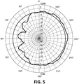
- the achieved radiation pattern is directive with a maximum of radiation on a semisphere region in an angular range of 180° (-90° ⁇ ⁇ ⁇ 90°), hence suitable to cover one side of a vehicle when installed in a side mirror as shown in the radiation pattern of Figure 5 .
- the optimal value of 32 mm for application.
- a central frequency of operation of 5.9GHz for application at the frequency range between 5.85 GHz to 5.925 GHz
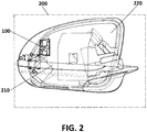
- FIGS 2 and 3 illustrate a preferred embodiment of the side mirror (200) of the invention, which incorporates the antenna system (100) previously described.
- the side mirror (200) may further incorporate a blinker (210), a mirror glass (220) with its respective metallic mirror reflector surface, and a frame (230). Since the most distortive elements to the radiation pattern of the antenna system (100) is the metallic reflector of the blinker (210) or the metallic mirror reflector surface of the mirror glass, said antenna system (100) is located in an outer region of the side mirror (200) moved as far away as possible from said distortive elements.
- figure 2 shows that the antenna system (100) is closer to the blinker (210) than the mirror glass (220), and with a vertical distance (D v ) between the antenna system (100) and the metallic reflector of the blinker (210) of 11 mm, and a horizontal distance (D h ) of 31 mm, adding up to a total distance (D t ) of 33 mm.
- D v vertical distance between the antenna system (100) and the metallic reflector of the blinker (210) of 11 mm
- D h horizontal distance
- figure 3 shows an example of recommended distances between the antenna system (100), the mirror glass (220) and the frame (230):
- Figure 4 schematically depicts a preferred embodiment of a vehicle (300) of the invention, which incorporates in its side mirrors (200) an antenna system (100) for each side mirror (200), also according to preferred embodiments thereof.
- a main axis (410) is defined by the central movement direction of the vehicle (300)
- an orthogonal axis (420) is defined perpendicular to said movement direction in a horizontal plane
- the antenna systems (100) are preferably disposed facing said orthogonal axis (420) in two opposite directions. Therefore, a first antenna system (100) covers a first lateral region (430) of the vehicle (300), whereas a second antenna system (100) covers a second lateral region (440), thereby obtaining an omnidirectional coverage.
- angular deviations ( ⁇ ) from the ideal orthogonal axis (420) may be induced while still preserving the desired omnidirectional coverage.
- Said angular deviations ( ⁇ ) may be induced by the design and morphology of the side mirrors (200), as well as by tilts and rotations of the mirror glass (220) or the same side mirror (200) due to user operation.
- Figure 5 shows experimental measurements of a preferred embodiment of the antenna system (100) of the invention, after full integration in the side mirror (200).
- the radiation pattern presents a gain exceeding 0 dBi in a complete semicircle around the device (that is, for all angles between 180° and 360°), demonstrating that omnidirectional coverage can be achieved by the combination of only two antenna systems.
- the frequency band of operation may be alternatively selected within one of the following ranges: 2.4 - 2.5 GHz, 3.5 - 3.6 GHz, 3.6 - 3.7 GHz or 4.9 - 5.8 GHz for WiFi communications; and 5.8-6.0 GHz for WiMAX communications.
- the modification of the frequency band of operation is straightforwardly achieved by updating the dimensions and distances of the PCB elements following the ranges and conditions previously described in this description.
- figure 6 illustrates the relation between the antenna gain and the ratio between the radiator width (W r ) and the dipole width (W d ), for a particular embodiment of the invention where the reflector (130) and the two radiating conductors are disposed in parallel.
- Two target gain threshold are shown: a first threshold (610) at 4 dBi and a second threshold (620) at 5 dBi.
- the first threshold (610) is exceeded whenever the radiator width (W r ) is less than six time larger than the dipole width (W d ).
- the second threshold (620) defines an optimal region (630), that is, an optimal range of width ratios, that for this specific case is comprised between a ratio of 0.6 and 2.6. Note that the particular gain values of each embodiment may vary depending on the exact disposition and geometry of the antenna system components.
Landscapes
- Engineering & Computer Science (AREA)
- Remote Sensing (AREA)
- Multimedia (AREA)
- Mechanical Engineering (AREA)
- Aerials With Secondary Devices (AREA)
- Details Of Aerials (AREA)
Abstract
Description
- The present invention has its application within the automotive and telecommunication industry and, especially, it relates to antenna systems for vehicles.
- A general object of the invention is to provide an antenna system for radio-frequency transmission and reception in all bands available for vehicular wireless communication applications.
- A more specific object of the invention is to provide an antenna system robust enough to allow small position and/or orientation modifications during the use of the vehicle, while featuring a small size that enables integration inside vehicles side mirrors.
- Transmitting and receiving information in moving vehicles has proven to be a challenging task for the automotive industry. Traditional approaches were based in the provision of external antennas in different parts of the vehicle, such as the roof or the rear window. However, these solutions, often based on monopoles, are greatly affected by the outer vehicle morphology, such as as the roof size, shape and tilt. As a consequence, some angles around the vehicle aren't adequately covered, hence lacking the omnidirectionality typically desired in these scenarios.
- Furthermore, traditional antennas present limitations in their operational frequency ranges. Originally, the main focus of automotive communications was to cover the bands used by amplitude modulation (AM) and frequency modulation (FM) broadcasts. However, the number and variety of services offered to vehicle users through wireless communications has rapidly escalated. Nowadays, these service include positioning and routing systems; radio and television broadcast; voice and data communications; internet access; automated signalling between Internet of Things (loT) devices; or coordination of commercial transport fleets; to name a few. This broad offer also implies that the antenna systems integrated in vehicles are required to cover greater frequency bands in an omnidirectional manner, and do such with a robustness that guarantees the communication quality required by the most demanding services.
- Several approaches have been proposed in order to enhance the capabilities of vehicular antenna systems. For example, the European
patent application EP 2 833 479 A1 discloses an antenna system, adapted to be installed on the front of the vehicle roof, which combines two directional antennas with opposite radiation directions. At least one of the antennas comprises a dipole disposed on a dielectric substrate of a printed circuit board (PCB), connected to a reflector plane through transmission lines. In order to provide the desired radiation pattern, the reflector plane is arranged perpendicularly to the PCB plane in which the dipole is disposed. The design prevents radiated power to be diverted into side lobes, enhancing overall system performance. - However, there is still the need of further antenna miniaturization, enabling omnidirectional schemes in any kind of vehicles while preserving high-performance. Antenna size reduction is sought after in order to facilitate integration in different parts of the vehicle, without compromising aesthetics, aerodynamics, nor the driver's visual range. It is also desirable that the antenna system provides radio-frequency transmission and reception in all bands available for vehicular wireless. Finally, it is desirable that the performance of the antenna system is robust enough as to allow small position and/or orientation modifications during the use of the vehicle, while maintaining the quality of the transmission.
- The current invention solves all the aforementioned shortcomings of the prior art, by providing a directive coplanar antenna system with a dipole and a reflector coplanarly disposed on a same dielectric substrate of a printed circuit board (PCB). The geometrical properties of said antenna system are adapted to guarantee a gain over a given threshold in a 180° degrees region, while preserving a small size that enables integration in the side mirrors of a vehicle.
- In a first aspect of the invention, an antenna system for a vehicle is disclosed. The antenna system comprises a dipole formed by two radiating conductors, connected to a reflector through transmission lines. All these elements (i.e. the two radiating conductors, the reflector and the transmission lines) are coplanar, that is, they are disposed on the same dielectric substrate of a printed circuit board. Said dielectric substrate is disposed on top of a ground plane, which is shorted to the radiating conductors through one of the transmission lines. The combination of the dipole and the reflector results in a directive antenna with a radiation that exceeds a given gain threshold (set during design) in an angular range of at least 180°, hence suitable to cover one side of a vehicle when installed in a side mirror.
- In order to maximize the antenna system directivity and gain in an operational frequency range with a given central wavelength, some geometrical properties are applied to the disposition of the two radiating conductors and the reflector:
- The reflector is separated from the two radiating conductors by a distance within a range of 0.3 times and 1 time the central wavelength. Preferably, said distance between the reflector and the two radiating conductors is within a range of 0.5 times and 0.8 times the central wavelength, and more preferably, between 0.6 times and 0.7 times the central wavelength.
- The reflector width, that is, for a rectangular-shaped reflector, the shorter dimension of the rectangle, is preferably equal or lesser than 0.5 times the central wavelength. More preferably, said reflector width is equal or lesser than 0.24 times the central wavelength, and even more preferably, equal or lesser than 0.2 times the central wavelength.
- The ratio between the reflector width and the dipole width (i.e. the shorter dimension of the area covered by each of the two radiating conductors) is less than 6. That is, the reflector is less than 6 times wider than the radiating conductors. More preferably, said ratio is between 0.8 and 1.8, and even more preferably, within the range 1.2 and 1.6, with an optimal value of approximately 1.4.
- According to two preferred options, the reflector can either be disposed in parallel or perpendicularly to the two radiating conductors.
- Preferably, the transmission lines are either implemented with microstrip lines or circulators, although any other type of transmission lines known in the state of the art may be used alternatively. An unbalance feeding antenna scheme with mictrostrip lines is preferably implemented. That is, a first microstrip line extends through a feeding line into an antenna feeding point, located near the reflector. The reflector is shorted to a ground plane and isolated from the feeding line. A second microstrip line, disposed in parallel to the first microstrip line is shorted to the ground plane. Each microstrip line connects to a radiating conductor, and has a length of a one-fourth of an effective wavelength within the frequency band of operation of the antenna system, preferably a central wavelength of said frequency band.
- Another aspect of the invention refers to side mirrors, incorporating an antenna system as the one previously described. Note that the term "side mirror" is used in this context to refer to any external protuberance or support element on a side of the vehicle, regardless of whether said support element comprises a reflective glass or not. For example, in some vehicles, the side mirror may comprise a camera, with or without an accompanying reflective surface.
- The antenna system is preferably integrated in an outer area of the side mirror, that is, a region of the side mirror furthest away from the main body of the vehicle, although alternative embodiments of the invention may incorporate the antenna system in other positions, such as a support element of the side mirrors. This region provides minimum distortion to the radiation diagram due to distortions caused by some typical distortive elements of the side mirror, such as a metallic part of a light reflector, a blinker, or a metallic mirror reflector surface. Therefore, in the particular embodiments where any of the aforementioned is present in the side mirror, the antenna system is preferably located in a position that maximizes distance to any metallic part.
- The antenna system is preferably disposed keeping the antenna main axis perpendicular to a main axis of the vehicle. That is, the antenna radiation pattern is directed laterally from the vehicle. The PCB of the antenna system can hence be disposed either horizontally or vertically, although the later is preferred.
- The antenna system of the invention provides a compact yet high-performance solution that can be implemented in a planar PCB, typically within a 1 mm thickness. This size reduction compared to volumetric approaches known in the state of the art enables its integration in side mirrors, fully covering both sides of the vehicle. Omnidirectional robust communication is provided, simultaneously enabling radio-frequency transmission and reception in all bands demanded by typical wireless. Due to the optimized performance of the antenna system, said omnidirectional communication is maintained even when the antenna is rotated or displaced due to the side mirror movements.
- For the purpose of aiding the understanding of the characteristics of the invention, according to a preferred practical embodiment thereof and in order to complement this description, the following figures are attached as an integral part thereof, having an illustrative and non-limiting character:
-
Figure 1 depicts the main elements integrated in the PCB of the antenna system of the invention, according to a preferred embodiment thereof. -
Figures 2 and3 are two views of a side mirror which incorporates the antenna system of the invention, according to preferred embodiments thereof. -
Figure 4 shows a vehicle which incorporates two antenna systems in its side mirrors, according to a preferred embodiment of the invention. -
Figure 5 shows a graph illustrating experimental measurements of the gain pattern of a preferred embodiment of the antenna system of the invention. -
Figure 6 illustrates an achievable gain as a function of a ratio between reflector width and dipole width, according to a preferred embodiment of the antenna system of the invention. -
Figure 1 shows a preferred embodiment of the antenna system (100) of the invention, which comprises two radiating conductors (110), two transmission lines (120) and a reflector (130), all coplanarly arranged on the same dielectric substrate of a printed circuit board. The dielectric substrate is disposed on a ground plane, being said ground plane shorted to the reflector (130) through a connection (140). As all the elements are implemented using the same PCB layers, the whole antenna system (100) can be integrated in a thickness of a few millimetres, enabling its installation in the side mirrors of a vehicle. Furthermore, the design and disposition of the radiating conductors (110) and the reflector (130) enables full coverage of a 180° angular section, achieving omnidirectional behaviour with the combination of only two antenna systems (100). - The antenna system (100) may be implemented with different dipole geometries, such as a bowtie-shaped configuration, an elliptic-shaped configuration, a diamond-shaped configuration, a rectangular-shaped configuration, a rectified horn-shaped configuration or a configuration wherein the radiating conductor (110) is formed by segments spaced at their extremes wherein corresponding opposing angles are formed. In this particular embodiment, each radiating conductor (110) of the dipole is formed by three regions:
- A first region (111) in a tapered shape starting at a minimum width (Wmin) which progressively increases up to a total dipole width (Wd) along a first length (L1). In this particular non-limiting example, the tapered shape is an isosceles trapezoid, The tapered shape base with the minimum width (Wmin) is connected to the transmission lines (120), whereas the tapered shape base with the total dipole width (Wd) is connected to the second region (112).
- A second region (112) in the shape of a rectangle, with a constant width substantially equal to the total dipole width (Wd), and a second length (L2).
- A third region (113) comprising a plurality of rectangular segments, each segment presenting a constant width equal to the total dipole width (Wd), and a third length (L3). This third region, which is optional, enables tuning the radiation pattern of the dipole after installation. This is achieved by connecting one or more rectangular segments of the third region (113) to the second region (112), hence modifying the aforementioned second length (L2).
- The width of the reflector (Wr) has to be lower than six times the total dipole width (Wd). More preferably, the reflector (130) is between 0.6 times and 2.6 times wider than the radiating conductors (110), with an optimal ratio of 1.4.
- The transmission lines (120) are two parallel microstrip lines disposed substantially perpendicularly to the dipole, that is, perpendicularly to an axis which connects the two radiating conductors (110). A first microstrip line (121) is connected on one end to a first radiating conductor (110), whereas the opposite end extends into a thinner feeding line (123) going in a direction towards the reflector (130), but being isolated from said reflector (130). Said opposite end is connected to a feeding point (150) disposed near the connections (140) used to short the reflector (130). An unbalance feeding antenna scheme is achieved between the feeding point (150) and the connections (140). A second microstrip line (122) is connected on one end to a second radiating conductor (110), whereas the opposite end is directly shorted to the ground plane. Both the first microstrip line (121) and the second microstrip line (122) have a length of one-fourth of an effective wavelength within the frequency band of operation, typically selected as the central wavelength of said frequency band. Note that in other particular embodiments, different microstrip lines geometries and/or different transmission lines (120) such as circulators may be used.
- Finally, the reflector (130) is a rectangular region which can be disposed in parallel or perpendicularly to the dipole. For example, for the particular frequency range of 5.85 GHz to 5.925 GHz, the reflector width (Wr) is preferably selected below a maximum of 26 mm in order to achieve a minimum gain of 2 dBi. More preferably, for a minimum gain of 4 dBi, the reflector width (Wr) is preferably selected below a maximum of 13 mm. Finally, for a minimum gain of 6 dBi, the reflector width (Wr) is preferably selected below a maximum of 11 mm.
- For the same frequency range of 5.85 GHz to 5.925 GHz, the distance between the reflector (130) and the radiating conductors (110) is preferably selected within the range between 19 mm and 49 mm, achieving a minimum gain of 2 dBi. More preferably, for a 4 dBi minimum gain, said distance is selected between 25 mm and 41 mm. Even more preferably, for a 6 dBi minimum gain, said distance is selected between 30 mm and 36 mm, with an optimal value of 32 mm.
- Note that due to the coplanar disposition of the antenna system, the ground plane (130) is not perpendicular to the radiating conductors (110). Therefore, the ground plane (130) does not work as an reflective element, but instead operates in junction with the radiating conductors (110) in order to generate a linear two array antenna elements distribution with directive radiation properties.
- As known from general antenna theory, when two antenna array elements are spaced a distance of d ∼ 2λ/3, with equal power incident in both array elements (in this case, the two radiating
conductors 110 and the ground plane 130), and a difference of phase near of 180° is implemented by a microstrip balun circuit (in this case, the transmission lines 120), the obtained radiation pattern (Gpattern) is directional, and can be mathematically described by the following formula of a cardiode:
- The achieved radiation pattern is directive with a maximum of radiation on a semisphere region in an angular range of 180° (-90° < θ < 90°), hence suitable to cover one side of a vehicle when installed in a side mirror as shown in the radiation pattern of
Figure 5 . - As previously explained, the optimal value of 32 mm for application. Considering a central frequency of operation of 5.9GHz (for application at the frequency range between 5.85 GHz to 5.925 GHz), and implementing the radiation conductors (110) and the ground plane (130) on a dielectric material of low electrical permittivity (εeff ∼ 1) like an implementation on a free space condition, the optimal distance between conductor (110) and ground plane (130) is computed as:

- Considering a 5.9GHz central frequency of operation, and implementing the radiation conductors (110) and the ground plane (130) on a commercial dielectric of higher electrical permittivity (εeff = 4.5), said optimal distance is modified as:

-
Figures 2 and3 illustrate a preferred embodiment of the side mirror (200) of the invention, which incorporates the antenna system (100) previously described. The side mirror (200) may further incorporate a blinker (210), a mirror glass (220) with its respective metallic mirror reflector surface, and a frame (230). Since the most distortive elements to the radiation pattern of the antenna system (100) is the metallic reflector of the blinker (210) or the metallic mirror reflector surface of the mirror glass, said antenna system (100) is located in an outer region of the side mirror (200) moved as far away as possible from said distortive elements. - In particular, the specific embodiment of
figure 2 shows that the antenna system (100) is closer to the blinker (210) than the mirror glass (220), and with a vertical distance (Dv) between the antenna system (100) and the metallic reflector of the blinker (210) of 11 mm, and a horizontal distance (Dh) of 31 mm, adding up to a total distance (Dt) of 33 mm. - Although the position of the rest of the elements is not as critical as the position of the blinker (210) or the mirror glass (220),
figure 3 shows an example of recommended distances between the antenna system (100), the mirror glass (220) and the frame (230): - A first maximum distance (D1) of 50 mm between the mirror glass (220) and the antenna system (100).
- A second maximum distance (D2) of 37 mm between the frame (230) and the antenna system (100).
- A first minimum distance (D3) of 19 mm between the frame (230) and the antenna system (100).
- A second minimum distance (D4) of 32 mm between the mirror glass (220) and the antenna system (100).
-
Figure 4 schematically depicts a preferred embodiment of a vehicle (300) of the invention, which incorporates in its side mirrors (200) an antenna system (100) for each side mirror (200), also according to preferred embodiments thereof. If a main axis (410) is defined by the central movement direction of the vehicle (300), and an orthogonal axis (420) is defined perpendicular to said movement direction in a horizontal plane, the antenna systems (100) are preferably disposed facing said orthogonal axis (420) in two opposite directions. Therefore, a first antenna system (100) covers a first lateral region (430) of the vehicle (300), whereas a second antenna system (100) covers a second lateral region (440), thereby obtaining an omnidirectional coverage. Nevertheless, note that small angular deviations (θ) from the ideal orthogonal axis (420) may be induced while still preserving the desired omnidirectional coverage. Said angular deviations (θ) may be induced by the design and morphology of the side mirrors (200), as well as by tilts and rotations of the mirror glass (220) or the same side mirror (200) due to user operation. -
Figure 5 shows experimental measurements of a preferred embodiment of the antenna system (100) of the invention, after full integration in the side mirror (200). The radiation pattern presents a gain exceeding 0 dBi in a complete semicircle around the device (that is, for all angles between 180° and 360°), demonstrating that omnidirectional coverage can be achieved by the combination of only two antenna systems. - Note that although the preferred embodiments have been described for the 5.85 GHz to 5.925 GHz, corresponding to Dedicated Short-Range Communications (DSRC) or Vehicle-to-Vehicle and Vehicle-to-Infrastructure (V2X or C2X), the frequency band of operation may be alternatively selected within one of the following ranges: 2.4 - 2.5 GHz, 3.5 - 3.6 GHz, 3.6 - 3.7 GHz or 4.9 - 5.8 GHz for WiFi communications; and 5.8-6.0 GHz for WiMAX communications. The modification of the frequency band of operation is straightforwardly achieved by updating the dimensions and distances of the PCB elements following the ranges and conditions previously described in this description.
- Finally,
figure 6 illustrates the relation between the antenna gain and the ratio between the radiator width (Wr) and the dipole width (Wd), for a particular embodiment of the invention where the reflector (130) and the two radiating conductors are disposed in parallel. Two target gain threshold are shown: a first threshold (610) at 4 dBi and a second threshold (620) at 5 dBi. The first threshold (610) is exceeded whenever the radiator width (Wr) is less than six time larger than the dipole width (Wd). The second threshold (620) defines an optimal region (630), that is, an optimal range of width ratios, that for this specific case is comprised between a ratio of 0.6 and 2.6. Note that the particular gain values of each embodiment may vary depending on the exact disposition and geometry of the antenna system components.
Claims (15)
- Antenna system (100) for a vehicle (300), comprising two radiating conductors (110) connected to a reflector (130) through transmission lines (120), wherein the transmission lines (120) are electromagnetically matched to a frequency band of operation with a central wavelength (λ), characterized in that the two radiating conductors (110) and the reflector (130) are coplanarly arranged on a same dielectric substrate of a printed circuit board, wherein the reflector (130) is separated from the two radiating conductors (110) by a distance between 0.3 times and 1 time the central wavelength (λ), and wherein the reflector (130) is less than 6 times wider than the radiating conductors (110).
- Antenna system (100) according to claim 1, wherein the reflector (130) is separated from the two radiating conductors (110) by a distance between 0.5 times and 0.8 times the central wavelength (λ).
- Antenna system (100) according to claim 2, wherein the reflector (130) is separated from the two radiating conductors (110) by a distance between 0.6 times and 0.7 times the central wavelength (λ).
- Antenna system (100) according to any of the previous claims, wherein the reflector (130) is between 0.6 times and 2.6 times wider than the radiating conductors (110).
- Antenna system (100) according to any of the previous claims, wherein a reflector width (Wr) is equal or less than 0.5 times the central wavelength (λ).
- Antenna system (100) according to claim 5, wherein the reflector width (Wr) is equal or less than 0.24 times the central wavelength (λ).
- Antenna system (100) according to claim 1, wherein the reflector (130) is arranged perpendicularly to the two radiating conductors (110).
- Antenna system (100) according to claim 1, wherein the reflector (130) is arranged in parallel to the two radiating conductors (110).
- Antenna system (100) according to any of the previous claims, wherein the transmission lines (120) comprise a first microstrip line (121) and a second microstrip line (122), both the first microstrip line (121) and the second microstrip line (122) having a length of an one-fourth of an effective wavelength within the frequency band of operation; wherein the first microstrip line (121) extends into a feeding line (123) going in a direction of the reflector (130), being the feeding line (123) isolated from said reflector (130) and connected to a feeding point (150); and wherein the second microstrip line (122) is arranged in parallel to the first microstrip line (121) and shorted to a ground plane through a connection (140).
- Antenna system (100) according to any of claims 1 to 8 wherein the transmission lines (120) comprise circulators that feed the two radiating conductors (110).
- Antenna system (100) according to any of the previous claims, wherein the two radiating conductors (110) are arranged in a configuration selected from a list comprising: a bowtie-shaped configuration, an elliptic-shaped configuration, a diamond-shaped configuration, a rectangular-shaped configuration, a rectified horn-shaped configuration and a configuration wherein the radiating conductor is formed by segments spaced at their ends wherein corresponding opposing angles are formed.
- Side mirror (200) for a vehicle (300), characterized in that the side mirror (200) further comprises an antenna system (100) according to any of claims 1 to 11.
- Side mirror according to claim 12 characterized in that the antenna system (100) is disposed with a radiation along an orthogonal axis (420), perpendicular to a main movement axis (410) of the vehicle (300).
- Side mirror according to claim 13, characterized in that the printed circuit board of the antenna system (100) is disposed vertically.
- Side mirror according to any of claims 12 to 14, wherein the side mirror (200) further comprises at least a distortive element to a radiation of the antenna system (100), selected from a metallic part of a light reflector, a blinker, and a metallic mirror reflector surface, characterized in that the antenna system (100) is disposed in an outer area of the side mirror (200) which maximizes a separation to the distortive element.
Priority Applications (2)
| Application Number | Priority Date | Filing Date | Title |
|---|---|---|---|
| EP17382871.6A EP3503291B1 (en) | 2017-12-20 | 2017-12-20 | Antenna system and side mirror for a vehicle incorporating said antenna system |
| US16/227,760 US10903555B2 (en) | 2017-12-20 | 2018-12-20 | Antenna system and side mirror for a vehicle incorporating said antenna |
Applications Claiming Priority (1)
| Application Number | Priority Date | Filing Date | Title |
|---|---|---|---|
| EP17382871.6A EP3503291B1 (en) | 2017-12-20 | 2017-12-20 | Antenna system and side mirror for a vehicle incorporating said antenna system |
Publications (2)
| Publication Number | Publication Date |
|---|---|
| EP3503291A1 true EP3503291A1 (en) | 2019-06-26 |
| EP3503291B1 EP3503291B1 (en) | 2023-04-26 |
Family
ID=60782155
Family Applications (1)
| Application Number | Title | Priority Date | Filing Date |
|---|---|---|---|
| EP17382871.6A Active EP3503291B1 (en) | 2017-12-20 | 2017-12-20 | Antenna system and side mirror for a vehicle incorporating said antenna system |
Country Status (2)
| Country | Link |
|---|---|
| US (1) | US10903555B2 (en) |
| EP (1) | EP3503291B1 (en) |
Cited By (1)
| Publication number | Priority date | Publication date | Assignee | Title |
|---|---|---|---|---|
| CN115064864A (en) * | 2022-08-18 | 2022-09-16 | 南京天朗防务科技有限公司 | Full-polarization antenna unit and antenna array |
Families Citing this family (4)
| Publication number | Priority date | Publication date | Assignee | Title |
|---|---|---|---|---|
| NL2022163B1 (en) * | 2018-12-10 | 2020-07-02 | Daf Trucks Nv | Wireless vehicle to vehicle communication system for mounting on a vehicle |
| EP3700011B1 (en) * | 2019-02-19 | 2022-03-30 | Advanced Automotive Antennas, S.L.U. | Antenna system for vehicles |
| US20230134263A1 (en) * | 2020-03-20 | 2023-05-04 | Telefonaktiebolaget Lm Ericsson (Publ) | Overmolded antenna radiator |
| WO2023008619A1 (en) * | 2021-07-29 | 2023-02-02 | 엘지전자 주식회사 | Electronic device having antenna |
Citations (3)
| Publication number | Priority date | Publication date | Assignee | Title |
|---|---|---|---|---|
| GB765465A (en) * | 1952-05-08 | 1957-01-09 | Standard Telephones Cables Ltd | Improvements in or relating to radio wave guide systems |
| US6046703A (en) * | 1998-11-10 | 2000-04-04 | Nutex Communication Corp. | Compact wireless transceiver board with directional printed circuit antenna |
| EP2833479A1 (en) | 2013-08-02 | 2015-02-04 | Advanced Automotive Antennas, S.L. | Antenna system for a vehicle |
Family Cites Families (8)
| Publication number | Priority date | Publication date | Assignee | Title |
|---|---|---|---|---|
| US5835057A (en) * | 1996-01-26 | 1998-11-10 | Kvh Industries, Inc. | Mobile satellite communication system including a dual-frequency, low-profile, self-steering antenna assembly |
| JP3085524B2 (en) * | 1996-11-18 | 2000-09-11 | 日本電業工作株式会社 | Dipole antenna with reflector |
| US6307524B1 (en) * | 2000-01-18 | 2001-10-23 | Core Technology, Inc. | Yagi antenna having matching coaxial cable and driven element impedances |
| US6342867B1 (en) * | 2000-03-31 | 2002-01-29 | Navcom Technology, Inc. | Nested turnstile antenna |
| US9425495B2 (en) * | 2013-02-01 | 2016-08-23 | Michael Clyde Walker | Active antenna ceiling tile |
| CN105552541B (en) * | 2015-12-25 | 2018-07-27 | 中国工程物理研究院电子工程研究所 | A kind of millimeter wave silicon chip load end-on-fire antenna |
| CN105591188B (en) * | 2015-12-31 | 2018-10-09 | 中国工程物理研究院电子工程研究所 | A kind of terahertz wave band silicon chip load Endfire antenna apparatus |
| DE102019126122A1 (en) * | 2018-09-28 | 2020-04-02 | Panasonic Intellectual Property Management Co., Ltd. | Vehicle lighting device |
-
2017
- 2017-12-20 EP EP17382871.6A patent/EP3503291B1/en active Active
-
2018
- 2018-12-20 US US16/227,760 patent/US10903555B2/en active Active
Patent Citations (3)
| Publication number | Priority date | Publication date | Assignee | Title |
|---|---|---|---|---|
| GB765465A (en) * | 1952-05-08 | 1957-01-09 | Standard Telephones Cables Ltd | Improvements in or relating to radio wave guide systems |
| US6046703A (en) * | 1998-11-10 | 2000-04-04 | Nutex Communication Corp. | Compact wireless transceiver board with directional printed circuit antenna |
| EP2833479A1 (en) | 2013-08-02 | 2015-02-04 | Advanced Automotive Antennas, S.L. | Antenna system for a vehicle |
Cited By (1)
| Publication number | Priority date | Publication date | Assignee | Title |
|---|---|---|---|---|
| CN115064864A (en) * | 2022-08-18 | 2022-09-16 | 南京天朗防务科技有限公司 | Full-polarization antenna unit and antenna array |
Also Published As
| Publication number | Publication date |
|---|---|
| US10903555B2 (en) | 2021-01-26 |
| US20190190137A1 (en) | 2019-06-20 |
| EP3503291B1 (en) | 2023-04-26 |
Similar Documents
| Publication | Publication Date | Title |
|---|---|---|
| US10903555B2 (en) | Antenna system and side mirror for a vehicle incorporating said antenna | |
| US11158933B2 (en) | Antenna system and method | |
| Ghafari et al. | A vehicular rooftop, shark-fin, multiband antenna for the GPS/LTE/cellular/DSRC systems | |
| US9385431B2 (en) | Dipole antenna | |
| US9653787B2 (en) | Antenna system for a vehicle | |
| US8089410B2 (en) | Dual-band antenna | |
| JP4141979B2 (en) | High frequency glass antenna for automobile | |
| JP2011091557A (en) | Antenna device | |
| US10897085B2 (en) | Antenna and antenna system | |
| US11495878B2 (en) | Multiband vehicle rooftop antenna assembly | |
| US11101568B1 (en) | Antenna with directional gain | |
| CN107768799B (en) | Antenna system | |
| KR102215657B1 (en) | Multi-band antenna and antenna assembly comprising the same for vehicle | |
| US10381717B2 (en) | Automotive antenna | |
| WO2011074419A1 (en) | Antenna | |
| CN216793985U (en) | Antenna device, glass, antenna system and vehicle | |
| CN113474944B (en) | Vehicle glazing | |
| KR102215658B1 (en) | Integrated antenna module and smart antenna devicee for vehicle comprising the same | |
| WO2020218116A1 (en) | Vehicle antenna | |
| KR20110105724A (en) | Car Glass Antenna and Car Window Glass | |
| JP2010045740A (en) | Vehicle antenna | |
| CN110957562A (en) | Antenna and electric automobile for V2X | |
| JPH1013125A (en) | Glass antenna for vehicle |
Legal Events
| Date | Code | Title | Description |
|---|---|---|---|
| PUAI | Public reference made under article 153(3) epc to a published international application that has entered the european phase |
Free format text: ORIGINAL CODE: 0009012 |
|
| STAA | Information on the status of an ep patent application or granted ep patent |
Free format text: STATUS: THE APPLICATION HAS BEEN PUBLISHED |
|
| AK | Designated contracting states |
Kind code of ref document: A1 Designated state(s): AL AT BE BG CH CY CZ DE DK EE ES FI FR GB GR HR HU IE IS IT LI LT LU LV MC MK MT NL NO PL PT RO RS SE SI SK SM TR |
|
| AX | Request for extension of the european patent |
Extension state: BA ME |
|
| STAA | Information on the status of an ep patent application or granted ep patent |
Free format text: STATUS: REQUEST FOR EXAMINATION WAS MADE |
|
| 17P | Request for examination filed |
Effective date: 20191219 |
|
| RBV | Designated contracting states (corrected) |
Designated state(s): AL AT BE BG CH CY CZ DE DK EE ES FI FR GB GR HR HU IE IS IT LI LT LU LV MC MK MT NL NO PL PT RO RS SE SI SK SM TR |
|
| STAA | Information on the status of an ep patent application or granted ep patent |
Free format text: STATUS: EXAMINATION IS IN PROGRESS |
|
| 17Q | First examination report despatched |
Effective date: 20200609 |
|
| STAA | Information on the status of an ep patent application or granted ep patent |
Free format text: STATUS: EXAMINATION IS IN PROGRESS |
|
| STAA | Information on the status of an ep patent application or granted ep patent |
Free format text: STATUS: EXAMINATION IS IN PROGRESS |
|
| GRAP | Despatch of communication of intention to grant a patent |
Free format text: ORIGINAL CODE: EPIDOSNIGR1 |
|
| STAA | Information on the status of an ep patent application or granted ep patent |
Free format text: STATUS: GRANT OF PATENT IS INTENDED |
|
| INTG | Intention to grant announced |
Effective date: 20221111 |
|
| GRAS | Grant fee paid |
Free format text: ORIGINAL CODE: EPIDOSNIGR3 |
|
| GRAA | (expected) grant |
Free format text: ORIGINAL CODE: 0009210 |
|
| STAA | Information on the status of an ep patent application or granted ep patent |
Free format text: STATUS: THE PATENT HAS BEEN GRANTED |
|
| AK | Designated contracting states |
Kind code of ref document: B1 Designated state(s): AL AT BE BG CH CY CZ DE DK EE ES FI FR GB GR HR HU IE IS IT LI LT LU LV MC MK MT NL NO PL PT RO RS SE SI SK SM TR |
|
| REG | Reference to a national code |
Ref country code: GB Ref legal event code: FG4D |
|
| REG | Reference to a national code |
Ref country code: CH Ref legal event code: EP |
|
| REG | Reference to a national code |
Ref country code: DE Ref legal event code: R096 Ref document number: 602017068034 Country of ref document: DE |
|
| REG | Reference to a national code |
Ref country code: AT Ref legal event code: REF Ref document number: 1563505 Country of ref document: AT Kind code of ref document: T Effective date: 20230515 |
|
| REG | Reference to a national code |
Ref country code: IE Ref legal event code: FG4D |
|
| REG | Reference to a national code |
Ref country code: LT Ref legal event code: MG9D |
|
| REG | Reference to a national code |
Ref country code: NL Ref legal event code: MP Effective date: 20230426 |
|
| REG | Reference to a national code |
Ref country code: AT Ref legal event code: MK05 Ref document number: 1563505 Country of ref document: AT Kind code of ref document: T Effective date: 20230426 |
|
| PG25 | Lapsed in a contracting state [announced via postgrant information from national office to epo] |
Ref country code: NL Free format text: LAPSE BECAUSE OF FAILURE TO SUBMIT A TRANSLATION OF THE DESCRIPTION OR TO PAY THE FEE WITHIN THE PRESCRIBED TIME-LIMIT Effective date: 20230426 |
|
| PG25 | Lapsed in a contracting state [announced via postgrant information from national office to epo] |
Ref country code: SE Free format text: LAPSE BECAUSE OF FAILURE TO SUBMIT A TRANSLATION OF THE DESCRIPTION OR TO PAY THE FEE WITHIN THE PRESCRIBED TIME-LIMIT Effective date: 20230426 Ref country code: PT Free format text: LAPSE BECAUSE OF FAILURE TO SUBMIT A TRANSLATION OF THE DESCRIPTION OR TO PAY THE FEE WITHIN THE PRESCRIBED TIME-LIMIT Effective date: 20230828 Ref country code: NO Free format text: LAPSE BECAUSE OF FAILURE TO SUBMIT A TRANSLATION OF THE DESCRIPTION OR TO PAY THE FEE WITHIN THE PRESCRIBED TIME-LIMIT Effective date: 20230726 Ref country code: ES Free format text: LAPSE BECAUSE OF FAILURE TO SUBMIT A TRANSLATION OF THE DESCRIPTION OR TO PAY THE FEE WITHIN THE PRESCRIBED TIME-LIMIT Effective date: 20230426 Ref country code: AT Free format text: LAPSE BECAUSE OF FAILURE TO SUBMIT A TRANSLATION OF THE DESCRIPTION OR TO PAY THE FEE WITHIN THE PRESCRIBED TIME-LIMIT Effective date: 20230426 |
|
| PG25 | Lapsed in a contracting state [announced via postgrant information from national office to epo] |
Ref country code: RS Free format text: LAPSE BECAUSE OF FAILURE TO SUBMIT A TRANSLATION OF THE DESCRIPTION OR TO PAY THE FEE WITHIN THE PRESCRIBED TIME-LIMIT Effective date: 20230426 Ref country code: PL Free format text: LAPSE BECAUSE OF FAILURE TO SUBMIT A TRANSLATION OF THE DESCRIPTION OR TO PAY THE FEE WITHIN THE PRESCRIBED TIME-LIMIT Effective date: 20230426 Ref country code: LV Free format text: LAPSE BECAUSE OF FAILURE TO SUBMIT A TRANSLATION OF THE DESCRIPTION OR TO PAY THE FEE WITHIN THE PRESCRIBED TIME-LIMIT Effective date: 20230426 Ref country code: LT Free format text: LAPSE BECAUSE OF FAILURE TO SUBMIT A TRANSLATION OF THE DESCRIPTION OR TO PAY THE FEE WITHIN THE PRESCRIBED TIME-LIMIT Effective date: 20230426 Ref country code: IS Free format text: LAPSE BECAUSE OF FAILURE TO SUBMIT A TRANSLATION OF THE DESCRIPTION OR TO PAY THE FEE WITHIN THE PRESCRIBED TIME-LIMIT Effective date: 20230826 Ref country code: HR Free format text: LAPSE BECAUSE OF FAILURE TO SUBMIT A TRANSLATION OF THE DESCRIPTION OR TO PAY THE FEE WITHIN THE PRESCRIBED TIME-LIMIT Effective date: 20230426 Ref country code: GR Free format text: LAPSE BECAUSE OF FAILURE TO SUBMIT A TRANSLATION OF THE DESCRIPTION OR TO PAY THE FEE WITHIN THE PRESCRIBED TIME-LIMIT Effective date: 20230727 |
|
| PG25 | Lapsed in a contracting state [announced via postgrant information from national office to epo] |
Ref country code: FI Free format text: LAPSE BECAUSE OF FAILURE TO SUBMIT A TRANSLATION OF THE DESCRIPTION OR TO PAY THE FEE WITHIN THE PRESCRIBED TIME-LIMIT Effective date: 20230426 |
|
| PG25 | Lapsed in a contracting state [announced via postgrant information from national office to epo] |
Ref country code: SK Free format text: LAPSE BECAUSE OF FAILURE TO SUBMIT A TRANSLATION OF THE DESCRIPTION OR TO PAY THE FEE WITHIN THE PRESCRIBED TIME-LIMIT Effective date: 20230426 |
|
| REG | Reference to a national code |
Ref country code: DE Ref legal event code: R097 Ref document number: 602017068034 Country of ref document: DE |
|
| PG25 | Lapsed in a contracting state [announced via postgrant information from national office to epo] |
Ref country code: SM Free format text: LAPSE BECAUSE OF FAILURE TO SUBMIT A TRANSLATION OF THE DESCRIPTION OR TO PAY THE FEE WITHIN THE PRESCRIBED TIME-LIMIT Effective date: 20230426 Ref country code: SK Free format text: LAPSE BECAUSE OF FAILURE TO SUBMIT A TRANSLATION OF THE DESCRIPTION OR TO PAY THE FEE WITHIN THE PRESCRIBED TIME-LIMIT Effective date: 20230426 Ref country code: RO Free format text: LAPSE BECAUSE OF FAILURE TO SUBMIT A TRANSLATION OF THE DESCRIPTION OR TO PAY THE FEE WITHIN THE PRESCRIBED TIME-LIMIT Effective date: 20230426 Ref country code: EE Free format text: LAPSE BECAUSE OF FAILURE TO SUBMIT A TRANSLATION OF THE DESCRIPTION OR TO PAY THE FEE WITHIN THE PRESCRIBED TIME-LIMIT Effective date: 20230426 Ref country code: DK Free format text: LAPSE BECAUSE OF FAILURE TO SUBMIT A TRANSLATION OF THE DESCRIPTION OR TO PAY THE FEE WITHIN THE PRESCRIBED TIME-LIMIT Effective date: 20230426 Ref country code: CZ Free format text: LAPSE BECAUSE OF FAILURE TO SUBMIT A TRANSLATION OF THE DESCRIPTION OR TO PAY THE FEE WITHIN THE PRESCRIBED TIME-LIMIT Effective date: 20230426 |
|
| PLBE | No opposition filed within time limit |
Free format text: ORIGINAL CODE: 0009261 |
|
| STAA | Information on the status of an ep patent application or granted ep patent |
Free format text: STATUS: NO OPPOSITION FILED WITHIN TIME LIMIT |
|
| 26N | No opposition filed |
Effective date: 20240129 |
|
| PG25 | Lapsed in a contracting state [announced via postgrant information from national office to epo] |
Ref country code: SI Free format text: LAPSE BECAUSE OF FAILURE TO SUBMIT A TRANSLATION OF THE DESCRIPTION OR TO PAY THE FEE WITHIN THE PRESCRIBED TIME-LIMIT Effective date: 20230426 |
|
| PG25 | Lapsed in a contracting state [announced via postgrant information from national office to epo] |
Ref country code: SI Free format text: LAPSE BECAUSE OF FAILURE TO SUBMIT A TRANSLATION OF THE DESCRIPTION OR TO PAY THE FEE WITHIN THE PRESCRIBED TIME-LIMIT Effective date: 20230426 Ref country code: IT Free format text: LAPSE BECAUSE OF FAILURE TO SUBMIT A TRANSLATION OF THE DESCRIPTION OR TO PAY THE FEE WITHIN THE PRESCRIBED TIME-LIMIT Effective date: 20230426 |
|
| REG | Reference to a national code |
Ref country code: CH Ref legal event code: PL |
|
| PG25 | Lapsed in a contracting state [announced via postgrant information from national office to epo] |
Ref country code: LU Free format text: LAPSE BECAUSE OF NON-PAYMENT OF DUE FEES Effective date: 20231220 |
|
| PG25 | Lapsed in a contracting state [announced via postgrant information from national office to epo] |
Ref country code: MC Free format text: LAPSE BECAUSE OF FAILURE TO SUBMIT A TRANSLATION OF THE DESCRIPTION OR TO PAY THE FEE WITHIN THE PRESCRIBED TIME-LIMIT Effective date: 20230426 |
|
| GBPC | Gb: european patent ceased through non-payment of renewal fee |
Effective date: 20231220 |
|
| REG | Reference to a national code |
Ref country code: BE Ref legal event code: MM Effective date: 20231231 |
|
| PG25 | Lapsed in a contracting state [announced via postgrant information from national office to epo] |
Ref country code: MC Free format text: LAPSE BECAUSE OF FAILURE TO SUBMIT A TRANSLATION OF THE DESCRIPTION OR TO PAY THE FEE WITHIN THE PRESCRIBED TIME-LIMIT Effective date: 20230426 Ref country code: LU Free format text: LAPSE BECAUSE OF NON-PAYMENT OF DUE FEES Effective date: 20231220 |
|
| REG | Reference to a national code |
Ref country code: IE Ref legal event code: MM4A |
|
| PG25 | Lapsed in a contracting state [announced via postgrant information from national office to epo] |
Ref country code: IE Free format text: LAPSE BECAUSE OF NON-PAYMENT OF DUE FEES Effective date: 20231220 |
|
| PG25 | Lapsed in a contracting state [announced via postgrant information from national office to epo] |
Ref country code: GB Free format text: LAPSE BECAUSE OF NON-PAYMENT OF DUE FEES Effective date: 20231220 |
|
| PG25 | Lapsed in a contracting state [announced via postgrant information from national office to epo] |
Ref country code: BE Free format text: LAPSE BECAUSE OF NON-PAYMENT OF DUE FEES Effective date: 20231231 |
|
| PG25 | Lapsed in a contracting state [announced via postgrant information from national office to epo] |
Ref country code: FR Free format text: LAPSE BECAUSE OF NON-PAYMENT OF DUE FEES Effective date: 20231231 |
|
| PG25 | Lapsed in a contracting state [announced via postgrant information from national office to epo] |
Ref country code: CH Free format text: LAPSE BECAUSE OF NON-PAYMENT OF DUE FEES Effective date: 20231231 |
|
| PG25 | Lapsed in a contracting state [announced via postgrant information from national office to epo] |
Ref country code: IE Free format text: LAPSE BECAUSE OF NON-PAYMENT OF DUE FEES Effective date: 20231220 Ref country code: GB Free format text: LAPSE BECAUSE OF NON-PAYMENT OF DUE FEES Effective date: 20231220 Ref country code: FR Free format text: LAPSE BECAUSE OF NON-PAYMENT OF DUE FEES Effective date: 20231231 Ref country code: CH Free format text: LAPSE BECAUSE OF NON-PAYMENT OF DUE FEES Effective date: 20231231 Ref country code: BE Free format text: LAPSE BECAUSE OF NON-PAYMENT OF DUE FEES Effective date: 20231231 |
|
| PG25 | Lapsed in a contracting state [announced via postgrant information from national office to epo] |
Ref country code: BG Free format text: LAPSE BECAUSE OF FAILURE TO SUBMIT A TRANSLATION OF THE DESCRIPTION OR TO PAY THE FEE WITHIN THE PRESCRIBED TIME-LIMIT Effective date: 20230426 |
|
| PG25 | Lapsed in a contracting state [announced via postgrant information from national office to epo] |
Ref country code: BG Free format text: LAPSE BECAUSE OF FAILURE TO SUBMIT A TRANSLATION OF THE DESCRIPTION OR TO PAY THE FEE WITHIN THE PRESCRIBED TIME-LIMIT Effective date: 20230426 |
|
| PGFP | Annual fee paid to national office [announced via postgrant information from national office to epo] |
Ref country code: DE Payment date: 20241210 Year of fee payment: 8 |