EP3503089A1 - Apparatus for the active control of the sound of the engine of a land vehicle and corresponding method - Google Patents
Apparatus for the active control of the sound of the engine of a land vehicle and corresponding method Download PDFInfo
- Publication number
- EP3503089A1 EP3503089A1 EP18212250.7A EP18212250A EP3503089A1 EP 3503089 A1 EP3503089 A1 EP 3503089A1 EP 18212250 A EP18212250 A EP 18212250A EP 3503089 A1 EP3503089 A1 EP 3503089A1
- Authority
- EP
- European Patent Office
- Prior art keywords
- engine
- sound
- modulation
- frequency
- roughness
- Prior art date
- Legal status (The legal status is an assumption and is not a legal conclusion. Google has not performed a legal analysis and makes no representation as to the accuracy of the status listed.)
- Granted
Links
Images



Classifications
-
- G—PHYSICS
- G10—MUSICAL INSTRUMENTS; ACOUSTICS
- G10K—SOUND-PRODUCING DEVICES; METHODS OR DEVICES FOR PROTECTING AGAINST, OR FOR DAMPING, NOISE OR OTHER ACOUSTIC WAVES IN GENERAL; ACOUSTICS NOT OTHERWISE PROVIDED FOR
- G10K15/00—Acoustics not otherwise provided for
- G10K15/02—Synthesis of acoustic waves
-
- G—PHYSICS
- G10—MUSICAL INSTRUMENTS; ACOUSTICS
- G10K—SOUND-PRODUCING DEVICES; METHODS OR DEVICES FOR PROTECTING AGAINST, OR FOR DAMPING, NOISE OR OTHER ACOUSTIC WAVES IN GENERAL; ACOUSTICS NOT OTHERWISE PROVIDED FOR
- G10K15/00—Acoustics not otherwise provided for
- G10K15/04—Sound-producing devices
-
- G—PHYSICS
- G10—MUSICAL INSTRUMENTS; ACOUSTICS
- G10K—SOUND-PRODUCING DEVICES; METHODS OR DEVICES FOR PROTECTING AGAINST, OR FOR DAMPING, NOISE OR OTHER ACOUSTIC WAVES IN GENERAL; ACOUSTICS NOT OTHERWISE PROVIDED FOR
- G10K2210/00—Details of active noise control [ANC] covered by G10K11/178 but not provided for in any of its subgroups
- G10K2210/10—Applications
- G10K2210/128—Vehicles
- G10K2210/1282—Automobiles
-
- G—PHYSICS
- G10—MUSICAL INSTRUMENTS; ACOUSTICS
- G10K—SOUND-PRODUCING DEVICES; METHODS OR DEVICES FOR PROTECTING AGAINST, OR FOR DAMPING, NOISE OR OTHER ACOUSTIC WAVES IN GENERAL; ACOUSTICS NOT OTHERWISE PROVIDED FOR
- G10K2210/00—Details of active noise control [ANC] covered by G10K11/178 but not provided for in any of its subgroups
- G10K2210/50—Miscellaneous
- G10K2210/51—Improving tonal quality, e.g. mimicking sports cars
Definitions
- the present invention relates to techniques for active generation of the sound of the internal-combustion or electric engine of a land vehicle, which comprises a device for detecting a fundamental frequency of the sound of the engine, and comprises a signal generator, which generates a plurality of signals representing sound waves that have spectral characteristics that depend upon a fundamental frequency and, in particular, also upon the state of the engine and a state of the accelerator pedal or of the torque produced by the engine.
- ASP Active Sound Profiling
- the aspects that refer to this need are multiple from the standpoint of the user and from the standpoint of the manufacturer.
- the passenger could expect to receive a particular sensation (provided also by the sound of the vehicle) inside the vehicle.
- the manufacturer could be interested in retaining the typical sound of the vehicle brand, even though modifications have been made that change the sound.
- the sensations originated by the sound of the vehicle are particularly correlated to the sound of the engine.
- roughness is used in engineering the quality of the sound in order to enhance the "sports-car” characteristic in the sound of the engine of a car.
- Roughness is linked to the perception of the modulated sound for sounds modulated in the bandwidth from 20 Hz to 300 Hz and reaches a maximum at modulation frequencies of approximately 70 Hz when applied to a pure tone at 1000 Hz with maximum modulation depth. Fluctuation strength is similar to roughness, is correlated to modulation at frequencies lower than 20 Hz, and reaches a maximum at modulation frequencies of approximately 4 Hz. Roughness is linked to the timbre or colour, whereas fluctuation strength is linked to the rhythm.
- roughness and fluctuation strength can be regulated by applying a modulation to the generated sound.
- the increasing roughness values are correlated to the presence of orders of harmonics of the fundamental frequency f E of the engine that are half-integer multiples of the fundamental frequency f E , namely, half-integer-order harmonics.
- an apparatus for active control of the sound of the engine of a land vehicle of a known type comprises, for example, a converter for converting the engine r.p.m. into a value of fundamental frequency of a sinusoidal wave and comprises a generator of harmonics, which generates harmonics of sinusoidal waves as a function of an accelerator-pedal signal, for example the percentage of travel of the pedal when it is pressed by the driver, which is a signal representative of the engine torque.
- an engine state supplied at input to the generator of harmonics is an engine state, i.e., an operating condition of the engine that is able to shape specifically the set of the harmonics that represent the engine noise, given the pedal or torque value; for example, the engine state may correspond to a cranking step or a heating step.
- the generator of harmonics will thus generate the harmonics also as a function of this information at input.
- Such an apparatus requires direct simulation of the engine noise, i.e., generation of a set of harmonics that constitutes the audio signal to be supplied to the speaker, directly introduced into which are the harmonics corresponding to the half-integer engine orders that are deemed necessary for emulating the "real" sound of the vehicle and for enabling a rougher sound to be obtained. Consequently, the aforesaid known apparatus substantially requires reproduction by the generator of an audio signal with a spectrum that as far as possible corresponds to that of the sound of the engine that it is desired to reproduce. Hence, the aforesaid apparatus is markedly constrained in the choices of the harmonics, and is thus far from flexible and does not enable precise and continuous control of the degree of roughness or other psycho-acoustic characteristics of the engine sound.
- the object of the present invention is to provide an improved apparatus that will enable effective modelling of psycho-acoustic characteristics of the sounds synthesised starting from the characteristics of speed and torque of the engine of a vehicle.
- the above object is achieved by an apparatus for active control of the sound of the engine of a land vehicle, as well as by a corresponding method that presents the characteristics recalled specifically in the ensuing claims.
- the solution according to the invention regards an apparatus for active control of the sound of the engine of a land vehicle that comprises a generator of signals that represent sound waves having spectral characteristics that depend upon the engine r.p.m., in particular upon the frequency of revolution of the engine and upon the corresponding harmonic components.
- These signals are also a function of an accelerator-pedal signal and/or a signal representing the engine torque, and, preferably, also moreover a function of the engine state.
- the above signals that represent sound waves can be synthesised starting from various types of waveforms, which comprise, inter alia, pure sinusoids, syncs, wavelets, and sound textures.
- the above apparatus for active control comprises a modulator, which includes a module configured for applying a modulation to the aforesaid sound waves or to a combination of the latter so as to control a value of roughness or fluctuation strength of an audio signal for driving an actuator that generates an engine noise or sound.
- This sound may, for example, be combined with the noise of an internal-combustion engine, or else correspond to the engine noise in the case of an electric engine.
- the apparatus described is hence able to modify the acoustic emission of the vehicle, both in the passenger compartment and in the exhaust line.
- the apparatus described is configured for generating a sound wave synthesised as a function of the engine orders, which is directly correlated to the engine r.p.m., the state of the accelerator pedal and the torque, and the engine state.
- the present apparatus is configured for applying a modulation to the sound wave thus generated. This modulation produces, for example, a rough sound, which is generally perceived as more aggressive, and as presenting a noise that evokes the sound of a sports-car engine.
- the apparatus described herein is configured for producing a given composition of sound waves that depend upon the integer engine orders, and directly determines the roughness of the sound by applying a modulation to the above composition, which in itself represents an audio signal that, via an acoustic actuator, reproduces an acoustic signal that corresponds to a desired generated final sound of the engine.
- the apparatus described hence comprises a generator of sound waves configured for depending upon a plurality of harmonics of the frequency of revolution of the engine.
- the sound waves correspond to the basic sinusoidal harmonics of the frequency of revolution of the engine, or fundamental frequency.
- the aforesaid sound waves are generated preferably as a function of other quantities that define the current engine state, the accelerator-pedal percentage displacement, possibly also a state of the accelerator pedal, and in any case a signal representing the engine torque, and moreover preferably also a signal representing the engine state.
- the sound waves synthesised by the aforesaid generator are combined, for example, via an adder, to obtain the composition of sound waves, to which, as has been mentioned, a respective modulation is then applied via a roughness-modulator block.
- the above modulation may be an amplitude modulation or a frequency modulation.
- the amplitude-modulation index (degree of modulation) and the amplitude-modulation frequency determine the roughness
- frequency modulation it is the frequency-modulation index and the modulation frequency of the modulating signal that determine the roughness of the resulting audio signal.
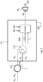
- FIG. 1 illustrated in Figure 1 is a principle diagram of the apparatus described herein, designated as a whole by the reference number 10.
- the components and modules included in this apparatus 10 are electronic modules that exchange signals, in particular electrical signals, and can be implemented via one or more processor modules, even included in one or more vehicle control units such as the ECU (Engine Control Unit) and/or electronic modules of a DSP (Digital Signal Processing) type.
- the apparatus 10 comprises a device for detecting a fundamental frequency f E of the sound of the engine, which is obtained via a converter 11, which receives, for example from the data network of the vehicle, i.e., a CAN bus, an engine speed ER, expressed as engine r.p.m.
- the above fundamental frequency f E is supplied at input to a generator 12 of signals that represent sound waves w 2 , ..., w N , in the sequel referred to, for brevity, as "sound waves w 2 , ..., w N ".
- the spectral characteristics of these sound waves w 2 , ..., w N supplied at output from the generator 12 are a function of the aforesaid fundamental frequency f E .
- these sound waves w 2 , ..., w N correspond to the basic harmonics of a sinusoidal signal having the fundamental frequency f E , i.e., sinusoidal signals that have frequencies that multiples of the fundamental frequency, namely, 2 ⁇ f E , 3 ⁇ f E , ..., n ⁇ f E .
- the dependence of the spectral characteristics upon the fundamental frequency f E is in this case of a simpler type in so far as the sinusoidal waves w 2 , ..., w N in the frequency domain are identified by spectral lines at frequencies that are multiples of the fundamental frequency, namely, 2 ⁇ f E , 3 ⁇ f E , ..., n ⁇ f E .
- the sound waves that can be generated are N-1, possibly starting from the one depending upon the second harmonic, if selected.
- the generator 12 receives at input also a set of control parameters, which comprise a signal representing the engine torque, in this case the percentage of travel of the accelerator pedal GP and also a pedal state SP, which indicates whether the accelerator pedal is depressed or not.
- these control parameters at input to the generator 12, which operates also as a function of these parameters, and not only as a function of the fundamental frequency f E and of the orders k also comprise an engine state SM, for example indicating whether the engine is a cranking state, an ignition state, a state of stopping and starting, an engine-off state, a stage of warming-up of the engine, etc.
- the generator 12 is configured for modifying, for example, the amplitude of each sinusoidal harmonic corresponding to a sound wave w 2 , ..., w N by varying the shape of the spectrum corresponding to the set of sound waves w 2 , ..., w N .
- the module 12 for generating sound waves the characteristics of which depend upon engine orders is configured for calculating, as a function of these inputs, N-1 sound waves, w 2 , ..., w N , that depend upon the order i ranging from 1 to N, respectively.
- the above sound waves w 2 , ..., w N are supplied at input to a modulator 13, which also receives at input the engine state SM and the active orders k and is configured for supplying at output a generated audio signal SG by adding together the harmonics w 2 , ..., w N in a resulting wave, designated by WR in Figure 2 , which is a more detailed illustration of the modulator 13.
- the resulting wave WR which in the example is a composition of the basic harmonics w 2 , ..., w N , or, more in general, of sound waves, is in turn modulated for controlling the roughness of a generated audio signal SG, which corresponds to the aforesaid resulting wave WR modulated by the modulator 13, as described more fully in what follows.
- the generated audio signal SG is an audio signal for driving an acoustic actuator 31, for example a speaker, which, under driving of the aforesaid generated sound signal SG, generates a sound or engine noise RM with the characteristics of roughness and the other psycho-acoustic characteristics associated to the generated sound signal SG.
- the modulator 13 operates under the control of modulation parameters represented by a modulation index m and by a modulation frequency f m , the value of which is determined as a function of the engine r.p.m. ER, for example by a vehicle control unit, i.e., a microprocessor module.
- the modulation index m may regard the amplitude modulation or else the frequency modulation (i.e., the deviation in frequency divided by the modulation frequency of the modulating signal).
- the modulation frequency f m is the frequency of the modulating signal in the two cases of amplitude modulation and frequency modulation. This makes it possible to set different roughness values for the generated audio signal SG as a function of the engine r.p.m. ER.
- Figure 2 illustrates in detail the modulator 13.
- the sound waves i.e., in the embodiment described, the sinusoidal harmonics w 2 , ..., w i , ..., w N , where w i is the i-th generic harmonic, which are calculated in the sound-wave generator 12 exit from the aforesaid generator 12 each on a different output or wire, the plurality of outputs being represented in the figures via the block 121, and are sent as inputs, which are consequently different from one another, to an adder block 131, which adds together the aforesaid basic harmonics w 2 , ..., w i , ..., w N to obtain a resulting wave WR.
- the aforesaid sum is computed also on sound waves other than harmonics.
- the resulting wave WR which corresponds to a composition of sound waves that depend upon the respective integer multiples of the frequency of engine r.p.m. f 2 to f n , i.e., in the example described here a composition of sinusoidal harmonics of the fundamental frequency f E , is used as carrier wave and supplied at input to a modulation block 132, which applies to the aforesaid carrier, i.e., resulting wave WR, a modulation with characteristics defined by the modulation index m and by the modulation frequency f m , supplied at input to the modulator 132, for example, as has been said, by a vehicle control unit.
- the values of the aforesaid modulation characteristics, namely, the modulation index m and the modulation frequency f m , used by the modulation block 132 for obtaining a certain value of roughness R also depend upon the engine r.p.m. ER and the engine state SM, which represents a state or condition of the vehicle.
- the aforesaid dependence is indicated, with a dashed arrow, by two inputs to the modulation block 132; however, in a preferred version, the modulation index m and the modulation frequency f m are regulated in the module, for example the control unit 33 represented in Figure 6 , that supplies just the modulation index m and the modulation frequency f m to the block 132.
- the block 132 may be configured, via a processor or a look-up table, for correcting autonomously the modulation index m and the modulation frequency f m as a function of the engine r.p.m. ER and of the engine state SM received directly by the block 132.
- the engine state SM may be an optional parameter.
- the apparatus described may be used by a user who manually enters the roughness values R (or fluctuation strength).
- the user can also use the apparatus described herein by manually entering values of modulation index and modulation frequency.
- the aforesaid diagram is in itself known and appears, for example in the publication by E. Zwicker, H. Fastl, "Psychoacoustics. Facts and Models" Springer-Verlag, Berlin, 1990.
- the vehicle control unit or the block 132 given a roughness value R of the generated audio signal SG to be obtained via modulation of the resulting signal WR, it is, for example, envisaged to access a table, obtained on the basis of diagrams like that of Figure 3 , which, as a function of the roughness value R, of the central frequency f c of the tone, i.e., the frequency of the carrier of the resulting wave WR to be obtained, and possibly of the values of engine r.p.m. ER and engine state SM, supplies the values of modulation index m and modulation frequency f m to be applied to the resulting wave WR.
- a table obtained on the basis of diagrams like that of Figure 3 , which, as a function of the roughness value R, of the central frequency f c of the tone, i.e., the frequency of the carrier of the resulting wave WR to be obtained, and possibly of the values of engine r.p.m. ER and engine state SM, supplies the values of
- the apparatus described herein is configured for generating the sound of the engine orders, for example the sinusoidal harmonics w 2 , ..., w i , ..., w N , and applies to the combination of the orders, i.e., to the resulting signal WR as just described, or else to each order, a calibratable, or adjustable, level of roughness R (or fluctuation strength) obtained via modulation.
- a calibratable, or adjustable, level of roughness R or fluctuation strength
- the level of roughness may be calibrated or adjusted directly via a setting made by the user of the roughness value R and a conversion, carried out by the apparatus, of the current engine r.p.m. into a modulation frequency and a modulation depth - or a number of values of modulation frequency and modulation depth, as explained with reference to the embodiment of Figure 5 .
- the aforesaid level of roughness R can also be calibrated or adjusted on the basis of other conditions of the vehicle.
- Figure 4 shows the plot of the frequency of the orders k, from the second order to the sixteenth order, of the engine as a function of the engine r.p.m. ER, the frequency increasing linearly with the latter.
- Figure 5 presents a block diagram of a variant embodiment 23 of the block 13, which comprises a modulator 232 that makes it possible to assign different values of modulation frequency f m to different orders.
- the above embodiment includes switches 133 arranged on each of the wires 121 at output from the generator 12, which make it possible to select each basic sinusoidal harmonic w i and send it to a respective modulation block 233, which receives at input a respective modulation index m i and a respective modulation frequency f mi and supplies at output a respective modulated basic sinusoidal harmonic wm i (m i , f mi ).
- the aforesaid respective modulated basic sinusoidal harmonic wm i is sent to an adder 234, which in this case, unlike in the case of the modulator 13, is hence located downstream of the modulator block 233, where it is added to the other modulated basic sinusoidal harmonics independently, obtaining as sum the generated audio signal SG, which is a composition of basic sinusoidal harmonics, in this case already modulated.
- the i-th modulation index m i and the i-th modulation frequency f mi depend upon the engine r.p.m. ER and possibly upon the engine state SM, these being parameters that, as in the case of the modulator 13, may be evaluated in the modulator 23 or in a vehicle control unit.
- each i-th order is modulated with different characteristics.
- the parameter k that indicates the active engine orders makes it possible to select which harmonics originated by the generator 12 to use.
- ER and engine state SM supplies the values of modulation index m i and modulation frequency f mi to be applied to the basic sinusoidal harmonics w i , which, hence, added together as modulated basic sinusoidal harmonics wm i (m i , f mi ) in the block 234, give rise to a generated audio signal SG with the aforesaid given value of roughness R.
- the method likewise envisages sending each sound wave to a respective modulator, which applies a modulation of its own, producing modulated sound waves, which are then added together to obtain a composition of modulated waves.
- the modulation frequency f m and the modulation index m must be functions of the carrier frequency f c , which, for a given i-th modulation block 233, corresponds to the frequency of the i-th harmonic w i calculated as a function of the engine r.p.m. ER, for example according to the diagram appearing in Figure 4 .
- the modulator 23 may not necessarily be used for obtaining the maximum value of roughness R in so far as the plurality of modulation blocks 233 may be configured also for enabling regulation of the roughness R of the generated signal SG on a wider range of roughness values, the reason being that the apparatus is configured in general for regulating the value of roughness by modifying the modulation values.
- each modulation block 232 may be configured as a function of the engine states SM, for example, the cranking state, the ignition state, the state of stopping and starting, the engine-off state, the state of warming-up of the engine, etc., the reason being that in the different engine states SM different vehicle conditions are present to which different sounds are associated.
- the modulation index and the modulation frequency are hence preferably functions of the engine states SM, both in the embodiment of Figure 2 and in the embodiment of Figure 5 .
- the apparatus is configured also in variant embodiments for controlling the fluctuation strength associated to the generated audio signal SG.
- the fluctuation strength is defined for lower frequencies than roughness, in particular as low as 20 Hz, accordingly lower modulation frequencies are used to obtain the typical sensations associated to the fluctuation strength.
- the apparatus described is configured for sending the generated audio signal SG into the passenger compartment of the land vehicle and/or into the exhaust line. This is preferably obtained by superimposing on the original sound of the vehicle, which propagates in the passenger compartment and/or in the exhaust line, a synthetic sound, i.e., the sound of the engine RM, generated by the apparatus described herein, which is a function of the engine r.p.m.
- ER in addition to other parameters, as described, comprising engine state SM, and/or torque (accelerator-pedal position and/or state), to obtain specific psycho-acoustic characteristics, in particular the roughness and possibly the fluctuation strength, which yield a specific desired sensation, for example a sensation similar to that created by the noise of a sports-car engine.
- the apparatus described herein may be implemented by configuring a microprocessor module using software, for example the dedicated ECU, namely, the ASM (Active-Sound Module), or other ECUs, or else may be implemented in the audio/infotainment system of the vehicle 30.
- software for example the dedicated ECU, namely, the ASM (Active-Sound Module), or other ECUs, or else may be implemented in the audio/infotainment system of the vehicle 30.
- the apparatus for active control of the sound of the engine described herein may be used both for vehicles with internal-combustion engines and for electric vehicles.
- Figure 6 illustrates an example of installation of the apparatus 10 that is implemented via software in an ECU 33 of a motor vehicle 30 and drives, via a driving signal SG, both an acoustic actuator 31, in the passenger compartment of the motor vehicle 30, and an acoustic actuator 32 in the exhaust line, which are, for example, both speakers or shakers for emitting the sound of the engine.
- the generated audio signal SG may be modulated differently according to the acoustic actuator to which it is sent, and also the actuators in one and the same context, for example in the passenger compartment, can receive different generated audio signals SG; for example, the right-hand speaker in the passenger compartment may receive a sound to be reproduced that is different from the one received by the left-hand speaker in the passenger compartment.
- the solution described advantageously envisages direct introduction of the roughness as a separate function by applying a modulation to the sound generated.
- the solution described does not call for the need to introduce the dependence, for example, upon half-integer orders, of the engine for generating an aggressive engine noise, but can directly carry out a modulation to obtain the desired roughness values.
- the solution described herein advantageously enables modification of the sound of the engine by generating an actual engine sound, both in the passenger compartment and in the exhaust line.
- the solution described may be advantageously applied both to internal-combustion engines and to electric engines, as well as to vehicles with hybrid propulsion systems.
- the sound generated by the apparatus and method described herein combines with the sound of the internal-combustion engine, whereas, in the case of application to pure electric-drive vehicles, the sound of the vehicle is, in actual fact, the sound generated.
Landscapes
- Physics & Mathematics (AREA)
- Engineering & Computer Science (AREA)
- Acoustics & Sound (AREA)
- Multimedia (AREA)
- Health & Medical Sciences (AREA)
- Audiology, Speech & Language Pathology (AREA)
- General Health & Medical Sciences (AREA)
- Fittings On The Vehicle Exterior For Carrying Loads, And Devices For Holding Or Mounting Articles (AREA)
- Soundproofing, Sound Blocking, And Sound Damping (AREA)
Abstract
Description
- The present invention relates to techniques for active generation of the sound of the internal-combustion or electric engine of a land vehicle, which comprises a device for detecting a fundamental frequency of the sound of the engine, and comprises a signal generator, which generates a plurality of signals representing sound waves that have spectral characteristics that depend upon a fundamental frequency and, in particular, also upon the state of the engine and a state of the accelerator pedal or of the torque produced by the engine.
- It is known to use in motor vehicles so-called ASP (Active Sound Profiling) systems, which have the aim of reproducing a given sound profile. ASP techniques can be adopted, for example, for improving the quality of sound inside the passenger compartment of a motor vehicle by modifying the engine noise inside the passenger compartment.
- The aspects that refer to this need are multiple from the standpoint of the user and from the standpoint of the manufacturer. On the one hand, the passenger could expect to receive a particular sensation (provided also by the sound of the vehicle) inside the vehicle. On the other hand, the manufacturer could be interested in retaining the typical sound of the vehicle brand, even though modifications have been made that change the sound. The sensations originated by the sound of the vehicle are particularly correlated to the sound of the engine.
- From the psycho-acoustic standpoint, this means finding a "recipe" capable of describing the perception of sound of the vehicle. Various formulas have been proposed, the majority of which present a combination of psycho-acoustic criteria regarding loudness, clarity, roughness, and fluctuation strength. In what follows, the terms "roughness" and "fluctuation strength" will be used.
- In particular, roughness is used in engineering the quality of the sound in order to enhance the "sports-car" characteristic in the sound of the engine of a car.
- Roughness is linked to the perception of the modulated sound for sounds modulated in the bandwidth from 20 Hz to 300 Hz and reaches a maximum at modulation frequencies of approximately 70 Hz when applied to a pure tone at 1000 Hz with maximum modulation depth. Fluctuation strength is similar to roughness, is correlated to modulation at frequencies lower than 20 Hz, and reaches a maximum at modulation frequencies of approximately 4 Hz. Roughness is linked to the timbre or colour, whereas fluctuation strength is linked to the rhythm.
- In synthetic sounds, roughness and fluctuation strength can be regulated by applying a modulation to the generated sound.
- In general, a rougher sound is perceived as more aggressive, this corresponding to a possible connotation of a sound that evokes the sound of a sports car. Hence, to obtain a perception of this sort on the part of the user it is deemed that a sound of the engine with high roughness values should be generated.
- When the sound of the engine is generated directly by the vehicle engine, the increasing roughness values are correlated to the presence of orders of harmonics of the fundamental frequency fE of the engine that are half-integer multiples of the fundamental frequency fE, namely, half-integer-order harmonics. In this regard, the engine orders k in general present integer values proportional to the number of strokes and cylinders of the engine. For instance, a four-stroke, four-cylinder engine has the first main engine order for k = 2 and all the main harmonics for k = 4, 6, 8 .... An order value k = 1 corresponds to the fundamental frequency fE, i.e., to the engine r.p.m. divided by sixty, namely the number of revolutions per second; for example, 1200 r.p.m. corresponds to a frequency of 20 Hz. The half-integer engine orders are all the orders for k = x+0.5, where x is an integer. In the example, the half-integer engine order k = 5.5 corresponds to a frequency peak at 110 Hz.
- In this framework, an apparatus for active control of the sound of the engine of a land vehicle of a known type comprises, for example, a converter for converting the engine r.p.m. into a value of fundamental frequency of a sinusoidal wave and comprises a generator of harmonics, which generates harmonics of sinusoidal waves as a function of an accelerator-pedal signal, for example the percentage of travel of the pedal when it is pressed by the driver, which is a signal representative of the engine torque. Moreover, supplied at input to the generator of harmonics is an engine state, i.e., an operating condition of the engine that is able to shape specifically the set of the harmonics that represent the engine noise, given the pedal or torque value; for example, the engine state may correspond to a cranking step or a heating step. The generator of harmonics will thus generate the harmonics also as a function of this information at input. Such an apparatus requires direct simulation of the engine noise, i.e., generation of a set of harmonics that constitutes the audio signal to be supplied to the speaker, directly introduced into which are the harmonics corresponding to the half-integer engine orders that are deemed necessary for emulating the "real" sound of the vehicle and for enabling a rougher sound to be obtained. Consequently, the aforesaid known apparatus substantially requires reproduction by the generator of an audio signal with a spectrum that as far as possible corresponds to that of the sound of the engine that it is desired to reproduce. Hence, the aforesaid apparatus is markedly constrained in the choices of the harmonics, and is thus far from flexible and does not enable precise and continuous control of the degree of roughness or other psycho-acoustic characteristics of the engine sound.
- The object of the present invention is to provide an improved apparatus that will enable effective modelling of psycho-acoustic characteristics of the sounds synthesised starting from the characteristics of speed and torque of the engine of a vehicle.
- According to the present invention, the above object is achieved by an apparatus for active control of the sound of the engine of a land vehicle, as well as by a corresponding method that presents the characteristics recalled specifically in the ensuing claims.
- The invention will now be described with reference to the annexed drawings, which are provided purely by way of non-limiting example and in which:
-
Figure 1 is a principle diagram of the apparatus described herein; -
Figure 2 is a more detailed schematic illustration of a part of the apparatus ofFigure 1 ; -
Figure 3 shows a diagram representing values of a quantity to be reproduced through the apparatus described herein; -
Figure 4 shows a diagram representing values of a further quantity to be reproduced through the apparatus described herein; -
Figure 5 is a schematic illustration of a further embodiment of the apparatus described herein; and -
Figure 6 is a principle diagram representing implementation of the apparatus described herein on a land vehicle. - In brief, the solution according to the invention regards an apparatus for active control of the sound of the engine of a land vehicle that comprises a generator of signals that represent sound waves having spectral characteristics that depend upon the engine r.p.m., in particular upon the frequency of revolution of the engine and upon the corresponding harmonic components. These signals are also a function of an accelerator-pedal signal and/or a signal representing the engine torque, and, preferably, also moreover a function of the engine state.
- The above signals that represent sound waves can be synthesised starting from various types of waveforms, which comprise, inter alia, pure sinusoids, syncs, wavelets, and sound textures.
- The above apparatus for active control comprises a modulator, which includes a module configured for applying a modulation to the aforesaid sound waves or to a combination of the latter so as to control a value of roughness or fluctuation strength of an audio signal for driving an actuator that generates an engine noise or sound. This sound may, for example, be combined with the noise of an internal-combustion engine, or else correspond to the engine noise in the case of an electric engine.
- The apparatus described is hence able to modify the acoustic emission of the vehicle, both in the passenger compartment and in the exhaust line.
- This is obtained by combining with the original sound of the vehicle a synthetic sound generated by the apparatus described.
- In one embodiment, the apparatus described is configured for generating a sound wave synthesised as a function of the engine orders, which is directly correlated to the engine r.p.m., the state of the accelerator pedal and the torque, and the engine state. Hence, the present apparatus is configured for applying a modulation to the sound wave thus generated. This modulation produces, for example, a rough sound, which is generally perceived as more aggressive, and as presenting a noise that evokes the sound of a sports-car engine.
- Hence, to obtain a rougher sound of the vehicle, instead of getting the synthesis of the sound wave to depend directly upon half-integer engine orders thus emulating the "real" behaviour of the vehicle, the apparatus described herein is configured for producing a given composition of sound waves that depend upon the integer engine orders, and directly determines the roughness of the sound by applying a modulation to the above composition, which in itself represents an audio signal that, via an acoustic actuator, reproduces an acoustic signal that corresponds to a desired generated final sound of the engine.
- The apparatus described hence comprises a generator of sound waves configured for depending upon a plurality of harmonics of the frequency of revolution of the engine. In one embodiment, the sound waves correspond to the basic sinusoidal harmonics of the frequency of revolution of the engine, or fundamental frequency. In addition, as has been said, the aforesaid sound waves are generated preferably as a function of other quantities that define the current engine state, the accelerator-pedal percentage displacement, possibly also a state of the accelerator pedal, and in any case a signal representing the engine torque, and moreover preferably also a signal representing the engine state. The sound waves synthesised by the aforesaid generator, in one embodiment, are combined, for example, via an adder, to obtain the composition of sound waves, to which, as has been mentioned, a respective modulation is then applied via a roughness-modulator block.
- The above modulation may be an amplitude modulation or a frequency modulation. In the case of an amplitude modulation, the amplitude-modulation index (degree of modulation) and the amplitude-modulation frequency determine the roughness, whereas in the case of frequency modulation it is the frequency-modulation index and the modulation frequency of the modulating signal that determine the roughness of the resulting audio signal.
- In this connection, illustrated in
Figure 1 is a principle diagram of the apparatus described herein, designated as a whole by thereference number 10. The components and modules included in thisapparatus 10 are electronic modules that exchange signals, in particular electrical signals, and can be implemented via one or more processor modules, even included in one or more vehicle control units such as the ECU (Engine Control Unit) and/or electronic modules of a DSP (Digital Signal Processing) type. Theapparatus 10 comprises a device for detecting a fundamental frequency fE of the sound of the engine, which is obtained via aconverter 11, which receives, for example from the data network of the vehicle, i.e., a CAN bus, an engine speed ER, expressed as engine r.p.m. (revolutions per minute), and supplies at output a corresponding value of fundamental frequency of the engine fE. It is here emphasised how conversion of the engine r.p.m. provides a very simple way of obtaining the fundamental frequency fE of the engine sound, given the relation with the frequency of revolution. - The above fundamental frequency fE is supplied at input to a
generator 12 of signals that represent sound waves w2, ..., wN, in the sequel referred to, for brevity, as "sound waves w2, ..., wN". The spectral characteristics of these sound waves w2, ..., wN supplied at output from thegenerator 12 are a function of the aforesaid fundamental frequency fE. In the example described herein, these sound waves w2, ..., wN correspond to the basic harmonics of a sinusoidal signal having the fundamental frequency fE, i.e., sinusoidal signals that have frequencies that multiples of the fundamental frequency, namely, 2·fE, 3·fE, ..., n·fE. Hence, the dependence of the spectral characteristics upon the fundamental frequency fE is in this case of a simpler type in so far as the sinusoidal waves w2, ..., wN in the frequency domain are identified by spectral lines at frequencies that are multiples of the fundamental frequency, namely, 2·fE, 3·fE, ..., n·fE. However, in variant embodiments, the sound waves w2, ..., wN may be waveforms different from pure sinusoidal waves, which are, however, a function of respective multiples of the fundamental frequency, f2 = 2·fE, f3 = 3·fE, ..., fn = n·fE, and hence determine, in the frequency domain, respective spectra, the position of which depends upon the respective multiples of the fundamental frequency but the shape of which is different from that of a spectral line; for example, associated to each is a respective spectrum with a given bandwidth. - Hence, the spectral characteristics of the sound waves w2, ..., wN, in the example, the harmonics of the fundamental frequency depend upon the engine orders, which are precisely those multiples of the frequency of rotation f2, ..., fn, whereas a parameter k represents the orders that are to be activated, i.e., the values of k of the orders of the engine upon which the generation is to be made to depend, for example k = 2, 3, 4. The values of k are integers, but may even be non-consecutive; in any case, the choice of the aforesaid values of k determines the number N of sound waves W2, ..., WN, which in the example just referred to will be N = 4. It should be noted that the sound waves that can be generated are N-1, possibly starting from the one depending upon the second harmonic, if selected. Moreover, the
generator 12 receives at input also a set of control parameters, which comprise a signal representing the engine torque, in this case the percentage of travel of the accelerator pedal GP and also a pedal state SP, which indicates whether the accelerator pedal is depressed or not. Moreover, these control parameters at input to thegenerator 12, which operates also as a function of these parameters, and not only as a function of the fundamental frequency fE and of the orders k, also comprise an engine state SM, for example indicating whether the engine is a cranking state, an ignition state, a state of stopping and starting, an engine-off state, a stage of warming-up of the engine, etc. As a function of the value of the above control parameters GP and SM, thegenerator 12 is configured for modifying, for example, the amplitude of each sinusoidal harmonic corresponding to a sound wave w2, ..., wN by varying the shape of the spectrum corresponding to the set of sound waves w2, ..., wN. - Hence, to sum up, the
module 12 for generating sound waves the characteristics of which depend upon engine orders is configured for calculating, as a function of these inputs, N-1 sound waves, w2, ..., wN, that depend upon the order i ranging from 1 to N, respectively. The sound wave of index i = 1, w1, in the example described, would be a sinusoid at the fundamental frequency fE, or in any case a waveform the spectral characteristics of which depend directly upon the frequency determined by the speed of rotation of the engine ER, but is not supplied by thegenerator 12 at output. - The above sound waves w2, ..., wN, i.e., the basic harmonics at output from the
generator 12, are supplied at input to amodulator 13, which also receives at input the engine state SM and the active orders k and is configured for supplying at output a generated audio signal SG by adding together the harmonics w2, ..., wN in a resulting wave, designated by WR inFigure 2 , which is a more detailed illustration of themodulator 13. The resulting wave WR, which in the example is a composition of the basic harmonics w2, ..., wN, or, more in general, of sound waves, is in turn modulated for controlling the roughness of a generated audio signal SG, which corresponds to the aforesaid resulting wave WR modulated by themodulator 13, as described more fully in what follows. - The generated audio signal SG is an audio signal for driving an
acoustic actuator 31, for example a speaker, which, under driving of the aforesaid generated sound signal SG, generates a sound or engine noise RM with the characteristics of roughness and the other psycho-acoustic characteristics associated to the generated sound signal SG. - The
modulator 13 operates under the control of modulation parameters represented by a modulation index m and by a modulation frequency fm, the value of which is determined as a function of the engine r.p.m. ER, for example by a vehicle control unit, i.e., a microprocessor module. As has been said, the modulation index m may regard the amplitude modulation or else the frequency modulation (i.e., the deviation in frequency divided by the modulation frequency of the modulating signal). Accordingly, the modulation frequency fm is the frequency of the modulating signal in the two cases of amplitude modulation and frequency modulation. This makes it possible to set different roughness values for the generated audio signal SG as a function of the engine r.p.m. ER. - In this regard,
Figure 2 illustrates in detail themodulator 13. - The sound waves, i.e., in the embodiment described, the sinusoidal harmonics w2, ..., wi, ..., wN, where wi is the i-th generic harmonic, which are calculated in the sound-
wave generator 12 exit from theaforesaid generator 12 each on a different output or wire, the plurality of outputs being represented in the figures via theblock 121, and are sent as inputs, which are consequently different from one another, to anadder block 131, which adds together the aforesaid basic harmonics w2, ..., wi, ..., wN to obtain a resulting wave WR. In general, the aforesaid sum is computed also on sound waves other than harmonics. The resulting wave WR, which corresponds to a composition of sound waves that depend upon the respective integer multiples of the frequency of engine r.p.m. f2 to fn, i.e., in the example described here a composition of sinusoidal harmonics of the fundamental frequency fE, is used as carrier wave and supplied at input to amodulation block 132, which applies to the aforesaid carrier, i.e., resulting wave WR, a modulation with characteristics defined by the modulation index m and by the modulation frequency fm, supplied at input to themodulator 132, for example, as has been said, by a vehicle control unit. - The values of the aforesaid modulation characteristics, namely, the modulation index m and the modulation frequency fm, used by the
modulation block 132 for obtaining a certain value of roughness R also depend upon the engine r.p.m. ER and the engine state SM, which represents a state or condition of the vehicle. In the figures, the aforesaid dependence is indicated, with a dashed arrow, by two inputs to themodulation block 132; however, in a preferred version, the modulation index m and the modulation frequency fm are regulated in the module, for example thecontrol unit 33 represented inFigure 6 , that supplies just the modulation index m and the modulation frequency fm to theblock 132. In variant embodiments, theblock 132 may be configured, via a processor or a look-up table, for correcting autonomously the modulation index m and the modulation frequency fm as a function of the engine r.p.m. ER and of the engine state SM received directly by theblock 132. - Hence, corresponding to different vehicle conditions are different degrees or levels of roughness R in the generated audio signal SG. This consequently makes it possible to choose different degrees or levels of roughness R in the generated audio signal SG as a function of the engine r.p.m. ER. Also in this case, the engine state SM may be an optional parameter.
- It is emphasised how in general the apparatus described may be used by a user who manually enters the roughness values R (or fluctuation strength). Alternatively, the user can also use the apparatus described herein by manually entering values of modulation index and modulation frequency.
- In this regard,
Figure 3 represents the variation of the roughness R as a function of the modulation frequency fm for a value of modulation index m = 1, as well as of a central frequency fc of the tone, i.e., the frequency of the carrier of the resulting wave WR. The aforesaid diagram is in itself known and appears, for example in the publication by E. Zwicker, H. Fastl, "Psychoacoustics. Facts and Models" Springer-Verlag, Berlin, 1990. - In general, in the vehicle control unit or the
block 132, given a roughness value R of the generated audio signal SG to be obtained via modulation of the resulting signal WR, it is, for example, envisaged to access a table, obtained on the basis of diagrams like that ofFigure 3 , which, as a function of the roughness value R, of the central frequency fc of the tone, i.e., the frequency of the carrier of the resulting wave WR to be obtained, and possibly of the values of engine r.p.m. ER and engine state SM, supplies the values of modulation index m and modulation frequency fm to be applied to the resulting wave WR. - In general, the apparatus described herein is configured for generating the sound of the engine orders, for example the sinusoidal harmonics w2, ..., wi, ..., wN, and applies to the combination of the orders, i.e., to the resulting signal WR as just described, or else to each order, a calibratable, or adjustable, level of roughness R (or fluctuation strength) obtained via modulation. In this way, the sound of the vehicle is completely and directly designed for generating a calibratable set of engine orders and for defining, through calibration, a predefined level of roughness. The level of roughness may be calibrated or adjusted directly via a setting made by the user of the roughness value R and a conversion, carried out by the apparatus, of the current engine r.p.m. into a modulation frequency and a modulation depth - or a number of values of modulation frequency and modulation depth, as explained with reference to the embodiment of
Figure 5 . The aforesaid level of roughness R can also be calibrated or adjusted on the basis of other conditions of the vehicle. - Moreover, it is to be considered that, especially when operating with tones, i.e., resulting waves WR, with central frequencies fc lower than 1 kHz, the maximum roughness is achieved with different frequency modulations at different central frequencies fc of the carrier of the resulting wave WR.
- In this regard,
Figure 4 shows the plot of the frequency of the orders k, from the second order to the sixteenth order, of the engine as a function of the engine r.p.m. ER, the frequency increasing linearly with the latter. - It may be noted from
Figure 4 how, in the case of the sound of an engine of a land vehicle, at the frequencies below a threshold S of 1 kHz all the orders are in general present, whereas beyond that threshold S only the frequencies of higher order are present, for example of an order k higher than 10. This means that, for a wide range of orders, to reach the maximum value of roughness it is necessary to assign different values of modulation frequency fm to different orders. - In this regard,
Figure 5 presents a block diagram of avariant embodiment 23 of theblock 13, which comprises amodulator 232 that makes it possible to assign different values of modulation frequency fm to different orders. - The above embodiment includes switches 133 arranged on each of the
wires 121 at output from thegenerator 12, which make it possible to select each basic sinusoidal harmonic wi and send it to arespective modulation block 233, which receives at input a respective modulation index mi and a respective modulation frequency fmi and supplies at output a respective modulated basic sinusoidal harmonic wmi (mi, fmi). The aforesaid respective modulated basic sinusoidal harmonic wmi is sent to anadder 234, which in this case, unlike in the case of themodulator 13, is hence located downstream of themodulator block 233, where it is added to the other modulated basic sinusoidal harmonics independently, obtaining as sum the generated audio signal SG, which is a composition of basic sinusoidal harmonics, in this case already modulated. As mentioned previously, the i-th modulation index mi and the i-th modulation frequency fmi depend upon the engine r.p.m. ER and possibly upon the engine state SM, these being parameters that, as in the case of themodulator 13, may be evaluated in themodulator 23 or in a vehicle control unit. Hence, each i-th order is modulated with different characteristics. The parameter k that indicates the active engine orders makes it possible to select which harmonics originated by thegenerator 12 to use. - Also in this case, in the vehicle control unit or in the
block 233, it is envisaged for example, given a value of roughness R (or fluctuation strength) of the generated audio signal SG to be obtained via modulation of the basic sinusoidal harmonics wi, to access a table, obtained on the basis of diagrams like that ofFigure 3 , which, as a function of the value of roughness R, of the central frequency fc of the tone of the signal to be obtained SG, and possibly of the values of engine r.p.m. ER and engine state SM, supplies the values of modulation index mi and modulation frequency fmi to be applied to the basic sinusoidal harmonics wi, which, hence, added together as modulated basic sinusoidal harmonics wmi (mi, fmi) in theblock 234, give rise to a generated audio signal SG with the aforesaid given value of roughness R. - Of course, in a similar way, in the case where the sound waves w2, ..., wN are represented by waveforms different from basic sinusoidal harmonics, for example sound textures or wavelets, the method likewise envisages sending each sound wave to a respective modulator, which applies a modulation of its own, producing modulated sound waves, which are then added together to obtain a composition of modulated waves.
- In order to achieve the maximum value of roughness R, i.e., the maximum of the curves of
Figure 3 , the modulation frequency fm and the modulation index m must be functions of the carrier frequency fc, which, for a given i-th modulation block 233, corresponds to the frequency of the i-th harmonic wi calculated as a function of the engine r.p.m. ER, for example according to the diagram appearing inFigure 4 . - It is emphasised how the
modulator 23 may not necessarily be used for obtaining the maximum value of roughness R in so far as the plurality of modulation blocks 233 may be configured also for enabling regulation of the roughness R of the generated signal SG on a wider range of roughness values, the reason being that the apparatus is configured in general for regulating the value of roughness by modifying the modulation values. - In addition, the
modulator 233, in particular eachmodulation block 232, may be configured as a function of the engine states SM, for example, the cranking state, the ignition state, the state of stopping and starting, the engine-off state, the state of warming-up of the engine, etc., the reason being that in the different engine states SM different vehicle conditions are present to which different sounds are associated. - The modulation index and the modulation frequency are hence preferably functions of the engine states SM, both in the embodiment of
Figure 2 and in the embodiment ofFigure 5 . - The apparatus is configured also in variant embodiments for controlling the fluctuation strength associated to the generated audio signal SG. In this case, since the fluctuation strength is defined for lower frequencies than roughness, in particular as low as 20 Hz, accordingly lower modulation frequencies are used to obtain the typical sensations associated to the fluctuation strength. The apparatus described is configured for sending the generated audio signal SG into the passenger compartment of the land vehicle and/or into the exhaust line. This is preferably obtained by superimposing on the original sound of the vehicle, which propagates in the passenger compartment and/or in the exhaust line, a synthetic sound, i.e., the sound of the engine RM, generated by the apparatus described herein, which is a function of the engine r.p.m. ER, in addition to other parameters, as described, comprising engine state SM, and/or torque (accelerator-pedal position and/or state), to obtain specific psycho-acoustic characteristics, in particular the roughness and possibly the fluctuation strength, which yield a specific desired sensation, for example a sensation similar to that created by the noise of a sports-car engine.
- Preferably, the apparatus described herein may be implemented by configuring a microprocessor module using software, for example the dedicated ECU, namely, the ASM (Active-Sound Module), or other ECUs, or else may be implemented in the audio/infotainment system of the
vehicle 30. - The apparatus for active control of the sound of the engine described herein may be used both for vehicles with internal-combustion engines and for electric vehicles.
-
Figure 6 illustrates an example of installation of theapparatus 10 that is implemented via software in anECU 33 of amotor vehicle 30 and drives, via a driving signal SG, both anacoustic actuator 31, in the passenger compartment of themotor vehicle 30, and anacoustic actuator 32 in the exhaust line, which are, for example, both speakers or shakers for emitting the sound of the engine. In variant embodiments, the generated audio signal SG may be modulated differently according to the acoustic actuator to which it is sent, and also the actuators in one and the same context, for example in the passenger compartment, can receive different generated audio signals SG; for example, the right-hand speaker in the passenger compartment may receive a sound to be reproduced that is different from the one received by the left-hand speaker in the passenger compartment. - Hence, from what has been described above, the advantages of the solution proposed emerge clearly.
- The solution described advantageously envisages direct introduction of the roughness as a separate function by applying a modulation to the sound generated. In other words, the solution described does not call for the need to introduce the dependence, for example, upon half-integer orders, of the engine for generating an aggressive engine noise, but can directly carry out a modulation to obtain the desired roughness values.
- The solution described herein advantageously enables modification of the sound of the engine by generating an actual engine sound, both in the passenger compartment and in the exhaust line.
- The solution described may be advantageously applied both to internal-combustion engines and to electric engines, as well as to vehicles with hybrid propulsion systems.
- In the case of application to vehicles with internal-combustion engine, the sound generated by the apparatus and method described herein combines with the sound of the internal-combustion engine, whereas, in the case of application to pure electric-drive vehicles, the sound of the vehicle is, in actual fact, the sound generated.
Claims (14)
- An apparatus for active generation of the sound of the engine of a land vehicle, which comprises a device for detecting a fundamental frequency (fE) of the sound of the engine and comprises a generator (12) for generating signals (w2, ..., wN) representing sound waves that have spectral characteristics that depend upon said fundamental frequency (fE), said apparatus being characterized in that it comprises a modulator (13; 23) including a module (132; 232) configured for applying a modulation to said waveforms (w2, ..., wN) so as to control a value of roughness (R) or fluctuation strength of an audio signal (SG) for driving an actuator (31, 32) that generates an engine noise (RM).
- The apparatus according to Claim 1, characterized in that said device for detecting a fundamental frequency (fE) of the sound of the engine comprises a converter (11) for converting the engine r.p.m. (ER) into a value of fundamental frequency (fE).
- The apparatus according to Claim 1, characterized in that said modulator (13) comprises a module (131) configured for adding together said sound waves (w2, ..., wN) generated by the generator (12) to obtain a resulting wave (WR), and said module (132) configured for modulating said sound waves (w2, ..., wN) is configured for modulating said resulting wave (WR) so as to control the value of roughness or fluctuation strength of an audio signal (SG) for driving an actuator (31, 32) that generates a noise (RM) of the engine.
- The apparatus according to Claim 1 or Claim 2, characterized in that said module (131) configured for modulating said resulting wave (WR) is configured for operating under the control of a modulation index (m) and of a modulation frequency (fm), which are determined as a function of the engine r.p.m. (ER).
- The apparatus according to Claim 1 or Claim 2, characterized in that said modulator (23) comprises: a module (232) configured for modulating said sound waves (w2, ..., wN), which comprises a plurality of sub-modules (233) for modulating each sound wave (wi) with characteristics that depend upon the i-th multiple (f2, ..., fN) of the fundamental frequency (fE), each submodule (233) being governed by a respective modulation index (mi) and a respective modulation frequency (fmi), and which receives at input said sinusoidal harmonic (wi) selected to supply at output a respective modulated harmonic (wmi); and said module (234) configured for adding sound waves (W1, ..., WN) which adds together said modulated sound waves (wmi) so as to control the value of roughness and/or fluctuation strength of an audio signal (SG) to supply at output said driving audio signal (SG).
- The apparatus according to any one of the preceding Claims 2 to 5, characterized in that said modulator (13; 23) is configured for sending different values of modulation index (m; mi) and modulation frequency (fm; fmi) as a function of the engine state (SM) .
- The apparatus according to any one of the preceding claims, characterized in that said modulation is an amplitude modulation and said modulator is configured for controlling the roughness or fluctuation strength of the sound as a function of an amplitude-modulation index (m) and an amplitude-modulation frequency (fm).
- The apparatus according to any one of the preceding claims, characterized in that said modulation is a frequency modulation, and said modulator (13; 23) is configured for controlling the roughness of the sound as a function of a frequency-modulation index and a modulation frequency of the modulating signal.
- The apparatus according to any one of the preceding claims, characterized in that it is configured for sending said driving audio signal (SG) to one or more acoustic actuators (31, 32) arranged in the passenger compartment of the land vehicle and/or in the exhaust line of the vehicle, a corresponding actuator (31, 32) superimposing on the original sound of the vehicle a sound generated under driving of said driving audio signal (SG).
- The apparatus according to any one of the preceding claims, characterized in that it is implemented in a microprocessor module (33) of the vehicle (30) or other ECUs available on board the vehicle.
- The apparatus according to any one of the preceding claims, characterized in that said generator (12) of signals (w2, ..., wN) representing sound waves that have spectral characteristics that depend upon said fundamental frequency (fE) comprises a generator (12) of harmonics, which generates harmonics of sinusoidal waves (w2, ..., wN) as a function of said fundamental frequency (fE), and in that said modulator is configured for applying a modulation to said harmonics of sinusoidal waves (w2, ..., wN).
- The apparatus according to any one of the preceding claims, characterized in that it is implemented in a vehicle with internal-combustion engine or in an electric or hybrid vehicle.
- The apparatus according to any one of the preceding claims, characterized in that said module configured for modulating sound waves (132; 232) is configured, given a value of roughness (R) or fluctuation strength of the generated audio signal (SG) to be obtained, for accessing a table, which, as a function of at least said value of roughness (R) or fluctuation strength of the central frequency (fc) of the generated audio signal (SG), supplies corresponding values of modulation index (m; mi) and modulation frequency (fm; fmi) to be applied to said (w2, ..., wN).
- A method for active generation of the sound of the engine of a land vehicle, which comprises converting (11) the engine r.p.m. (ER) into a value of fundamental frequency (fE) and generating (12) sound waves, in particular sinusoidal harmonics, (w2, ..., wN) as a function of said fundamental frequency (fE), said method being characterized in that it comprises modulating said sound waves (w2, ..., wN) so as to control the value of roughness or fluctuation strength of an audio signal (SG) for driving an actuator (31, 32), which generates an engine noise (RM).
Applications Claiming Priority (1)
| Application Number | Priority Date | Filing Date | Title |
|---|---|---|---|
| IT201700149307 | 2017-12-22 |
Publications (2)
| Publication Number | Publication Date |
|---|---|
| EP3503089A1 true EP3503089A1 (en) | 2019-06-26 |
| EP3503089B1 EP3503089B1 (en) | 2023-10-18 |
Family
ID=61873662
Family Applications (1)
| Application Number | Title | Priority Date | Filing Date |
|---|---|---|---|
| EP18212250.7A Active EP3503089B1 (en) | 2017-12-22 | 2018-12-13 | Apparatus for the active control of the sound of the engine of a land vehicle and corresponding method |
Country Status (2)
| Country | Link |
|---|---|
| US (1) | US11062690B2 (en) |
| EP (1) | EP3503089B1 (en) |
Families Citing this family (3)
| Publication number | Priority date | Publication date | Assignee | Title |
|---|---|---|---|---|
| IT201800007193A1 (en) | 2018-07-13 | 2020-01-13 | "Process of generating an audio signal, in particular for the active control of the engine sound of a land vehicle, and related apparatus" | |
| JP2021102416A (en) * | 2019-12-25 | 2021-07-15 | 株式会社デンソーエレクトロニクス | Sound output device |
| JP7421725B2 (en) * | 2020-01-21 | 2024-01-25 | マツダ株式会社 | Vehicle sound generator |
Citations (4)
| Publication number | Priority date | Publication date | Assignee | Title |
|---|---|---|---|---|
| US5635903A (en) * | 1993-12-21 | 1997-06-03 | Honda Giken Kogyo Kabushiki Kaisha | Simulated sound generator for electric vehicles |
| DE102011108124A1 (en) * | 2011-07-20 | 2012-03-15 | Daimler Ag | Method for producing synthetic drive noise for e.g. electrical vehicle, involves generating periodic control signals such that base signal is modulated via periodic modulation signal, where base signal depends on operating parameters |
| US20120148066A1 (en) * | 2005-03-11 | 2012-06-14 | Yamaha Corporation | Engine sound processing system |
| FR3026218A1 (en) * | 2014-09-18 | 2016-03-25 | Peugeot Citroen Automobiles Sa | SOUND SYNTHESIS DEVICE FOR THE ACTIVE COLORING OF THE NOISE OF A VEHICLE ENGINE |
Family Cites Families (3)
| Publication number | Priority date | Publication date | Assignee | Title |
|---|---|---|---|---|
| EP2663094B1 (en) * | 2012-05-09 | 2014-12-24 | Oticon A/s | Methods and apparatus for processing audio signals |
| EP2685448B1 (en) * | 2012-07-12 | 2018-09-05 | Harman Becker Automotive Systems GmbH | Engine sound synthesis |
| EP2884488B1 (en) * | 2013-12-16 | 2021-03-31 | Harman Becker Automotive Systems GmbH | Active noise control system |
-
2018
- 2018-12-13 EP EP18212250.7A patent/EP3503089B1/en active Active
- 2018-12-19 US US16/225,379 patent/US11062690B2/en not_active Expired - Fee Related
Patent Citations (4)
| Publication number | Priority date | Publication date | Assignee | Title |
|---|---|---|---|---|
| US5635903A (en) * | 1993-12-21 | 1997-06-03 | Honda Giken Kogyo Kabushiki Kaisha | Simulated sound generator for electric vehicles |
| US20120148066A1 (en) * | 2005-03-11 | 2012-06-14 | Yamaha Corporation | Engine sound processing system |
| DE102011108124A1 (en) * | 2011-07-20 | 2012-03-15 | Daimler Ag | Method for producing synthetic drive noise for e.g. electrical vehicle, involves generating periodic control signals such that base signal is modulated via periodic modulation signal, where base signal depends on operating parameters |
| FR3026218A1 (en) * | 2014-09-18 | 2016-03-25 | Peugeot Citroen Automobiles Sa | SOUND SYNTHESIS DEVICE FOR THE ACTIVE COLORING OF THE NOISE OF A VEHICLE ENGINE |
Also Published As
| Publication number | Publication date |
|---|---|
| EP3503089B1 (en) | 2023-10-18 |
| US11062690B2 (en) | 2021-07-13 |
| US20190206384A1 (en) | 2019-07-04 |
Similar Documents
| Publication | Publication Date | Title |
|---|---|---|
| JP7454119B2 (en) | Vehicle sound generator | |
| US8155343B2 (en) | Engine sound processing system | |
| EP3503089B1 (en) | Apparatus for the active control of the sound of the engine of a land vehicle and corresponding method | |
| US20130038435A1 (en) | Vehicle running warning device | |
| EP3288023B1 (en) | System and method for synthesizing an engine sound | |
| KR20150047980A (en) | Apparatus and method for controlling virtual engine sound in responding to autocruise speed settings | |
| CN113496695A (en) | Motor noise masking | |
| KR20190118136A (en) | Method and apparatus for controlling vehicle sound in a vehicle | |
| EP3915836B1 (en) | Control system, vehicle and method | |
| CN107077839A (en) | For the speech synthesizing device actively rendered for Vehicle Engine Noise | |
| JP2012066688A (en) | Vehicle-approach reporting device | |
| JP5061585B2 (en) | Fuel consumption notification device | |
| Maunder et al. | System for augmenting the in-cabin sound of electric vehicles | |
| Maunder | Experiences Tuning an Augmented Power Unit Sound System for Both Interior and Exterior of an Electric Car | |
| JP7573927B2 (en) | Running sound generating device and running sound generating method | |
| EP3821427B1 (en) | Method for generating an audio signal, in particular for active control of the sound of the engine of a land vehicle, and corresponding apparatus | |
| CN114901517A (en) | Sound output device | |
| JP2888138B2 (en) | Sound effect generator | |
| CN120171421A (en) | A sound and light control method, device, electronic device and storage medium | |
| KR20210046124A (en) | Indoor sound control method and system of vehicle | |
| JP7627993B2 (en) | Running sound generating device and running sound generating method | |
| US20200007981A1 (en) | Method for generating a sound data set for output through a loudspeaker of a motor vehicle | |
| WO2026041970A1 (en) | Automotive control for emitting a sound indicative of a motor vehicle dynamics | |
| JPH07306689A (en) | Sound effect addition device | |
| JPH07302095A (en) | Sound effect addition device |
Legal Events
| Date | Code | Title | Description |
|---|---|---|---|
| PUAI | Public reference made under article 153(3) epc to a published international application that has entered the european phase |
Free format text: ORIGINAL CODE: 0009012 |
|
| STAA | Information on the status of an ep patent application or granted ep patent |
Free format text: STATUS: THE APPLICATION HAS BEEN PUBLISHED |
|
| AK | Designated contracting states |
Kind code of ref document: A1 Designated state(s): AL AT BE BG CH CY CZ DE DK EE ES FI FR GB GR HR HU IE IS IT LI LT LU LV MC MK MT NL NO PL PT RO RS SE SI SK SM TR |
|
| AX | Request for extension of the european patent |
Extension state: BA ME |
|
| STAA | Information on the status of an ep patent application or granted ep patent |
Free format text: STATUS: REQUEST FOR EXAMINATION WAS MADE |
|
| 17P | Request for examination filed |
Effective date: 20191219 |
|
| RBV | Designated contracting states (corrected) |
Designated state(s): AL AT BE BG CH CY CZ DE DK EE ES FI FR GB GR HR HU IE IS IT LI LT LU LV MC MK MT NL NO PL PT RO RS SE SI SK SM TR |
|
| RAP1 | Party data changed (applicant data changed or rights of an application transferred) |
Owner name: MARELLI EUROPE S.P.A. |
|
| RIN1 | Information on inventor provided before grant (corrected) |
Inventor name: AMBROSINO, MASSIMO Inventor name: PAGLIANO, PIERANGELO Inventor name: NESCI, WALTER Inventor name: ARMENI, SAVERIO Inventor name: DE CESARIS, SIMONA Inventor name: LA SANA, MARCO |
|
| STAA | Information on the status of an ep patent application or granted ep patent |
Free format text: STATUS: EXAMINATION IS IN PROGRESS |
|
| 17Q | First examination report despatched |
Effective date: 20220621 |
|
| GRAP | Despatch of communication of intention to grant a patent |
Free format text: ORIGINAL CODE: EPIDOSNIGR1 |
|
| STAA | Information on the status of an ep patent application or granted ep patent |
Free format text: STATUS: GRANT OF PATENT IS INTENDED |
|
| INTG | Intention to grant announced |
Effective date: 20230519 |
|
| INTG | Intention to grant announced |
Effective date: 20230519 |
|
| GRAS | Grant fee paid |
Free format text: ORIGINAL CODE: EPIDOSNIGR3 |
|
| GRAA | (expected) grant |
Free format text: ORIGINAL CODE: 0009210 |
|
| STAA | Information on the status of an ep patent application or granted ep patent |
Free format text: STATUS: THE PATENT HAS BEEN GRANTED |
|
| AK | Designated contracting states |
Kind code of ref document: B1 Designated state(s): AL AT BE BG CH CY CZ DE DK EE ES FI FR GB GR HR HU IE IS IT LI LT LU LV MC MK MT NL NO PL PT RO RS SE SI SK SM TR |
|
| REG | Reference to a national code |
Ref country code: GB Ref legal event code: FG4D |
|
| REG | Reference to a national code |
Ref country code: CH Ref legal event code: EP |
|
| REG | Reference to a national code |
Ref country code: IE Ref legal event code: FG4D |
|
| REG | Reference to a national code |
Ref country code: DE Ref legal event code: R096 Ref document number: 602018059505 Country of ref document: DE |
|
| REG | Reference to a national code |
Ref country code: LT Ref legal event code: MG9D |
|
| REG | Reference to a national code |
Ref country code: NL Ref legal event code: MP Effective date: 20231018 |
|
| REG | Reference to a national code |
Ref country code: AT Ref legal event code: MK05 Ref document number: 1623176 Country of ref document: AT Kind code of ref document: T Effective date: 20231018 |
|
| PG25 | Lapsed in a contracting state [announced via postgrant information from national office to epo] |
Ref country code: NL Free format text: LAPSE BECAUSE OF FAILURE TO SUBMIT A TRANSLATION OF THE DESCRIPTION OR TO PAY THE FEE WITHIN THE PRESCRIBED TIME-LIMIT Effective date: 20231018 |
|
| PG25 | Lapsed in a contracting state [announced via postgrant information from national office to epo] |
Ref country code: GR Free format text: LAPSE BECAUSE OF FAILURE TO SUBMIT A TRANSLATION OF THE DESCRIPTION OR TO PAY THE FEE WITHIN THE PRESCRIBED TIME-LIMIT Effective date: 20240119 |
|
| PG25 | Lapsed in a contracting state [announced via postgrant information from national office to epo] |
Ref country code: IS Free format text: LAPSE BECAUSE OF FAILURE TO SUBMIT A TRANSLATION OF THE DESCRIPTION OR TO PAY THE FEE WITHIN THE PRESCRIBED TIME-LIMIT Effective date: 20240218 |
|
| PG25 | Lapsed in a contracting state [announced via postgrant information from national office to epo] |
Ref country code: LT Free format text: LAPSE BECAUSE OF FAILURE TO SUBMIT A TRANSLATION OF THE DESCRIPTION OR TO PAY THE FEE WITHIN THE PRESCRIBED TIME-LIMIT Effective date: 20231018 |
|
| PG25 | Lapsed in a contracting state [announced via postgrant information from national office to epo] |
Ref country code: AT Free format text: LAPSE BECAUSE OF FAILURE TO SUBMIT A TRANSLATION OF THE DESCRIPTION OR TO PAY THE FEE WITHIN THE PRESCRIBED TIME-LIMIT Effective date: 20231018 |
|
| PG25 | Lapsed in a contracting state [announced via postgrant information from national office to epo] |
Ref country code: ES Free format text: LAPSE BECAUSE OF FAILURE TO SUBMIT A TRANSLATION OF THE DESCRIPTION OR TO PAY THE FEE WITHIN THE PRESCRIBED TIME-LIMIT Effective date: 20231018 |
|
| PG25 | Lapsed in a contracting state [announced via postgrant information from national office to epo] |
Ref country code: LT Free format text: LAPSE BECAUSE OF FAILURE TO SUBMIT A TRANSLATION OF THE DESCRIPTION OR TO PAY THE FEE WITHIN THE PRESCRIBED TIME-LIMIT Effective date: 20231018 Ref country code: IS Free format text: LAPSE BECAUSE OF FAILURE TO SUBMIT A TRANSLATION OF THE DESCRIPTION OR TO PAY THE FEE WITHIN THE PRESCRIBED TIME-LIMIT Effective date: 20240218 Ref country code: GR Free format text: LAPSE BECAUSE OF FAILURE TO SUBMIT A TRANSLATION OF THE DESCRIPTION OR TO PAY THE FEE WITHIN THE PRESCRIBED TIME-LIMIT Effective date: 20240119 Ref country code: ES Free format text: LAPSE BECAUSE OF FAILURE TO SUBMIT A TRANSLATION OF THE DESCRIPTION OR TO PAY THE FEE WITHIN THE PRESCRIBED TIME-LIMIT Effective date: 20231018 Ref country code: BG Free format text: LAPSE BECAUSE OF FAILURE TO SUBMIT A TRANSLATION OF THE DESCRIPTION OR TO PAY THE FEE WITHIN THE PRESCRIBED TIME-LIMIT Effective date: 20240118 Ref country code: AT Free format text: LAPSE BECAUSE OF FAILURE TO SUBMIT A TRANSLATION OF THE DESCRIPTION OR TO PAY THE FEE WITHIN THE PRESCRIBED TIME-LIMIT Effective date: 20231018 Ref country code: PT Free format text: LAPSE BECAUSE OF FAILURE TO SUBMIT A TRANSLATION OF THE DESCRIPTION OR TO PAY THE FEE WITHIN THE PRESCRIBED TIME-LIMIT Effective date: 20240219 |
|
| PG25 | Lapsed in a contracting state [announced via postgrant information from national office to epo] |
Ref country code: SE Free format text: LAPSE BECAUSE OF FAILURE TO SUBMIT A TRANSLATION OF THE DESCRIPTION OR TO PAY THE FEE WITHIN THE PRESCRIBED TIME-LIMIT Effective date: 20231018 Ref country code: RS Free format text: LAPSE BECAUSE OF FAILURE TO SUBMIT A TRANSLATION OF THE DESCRIPTION OR TO PAY THE FEE WITHIN THE PRESCRIBED TIME-LIMIT Effective date: 20231018 Ref country code: PL Free format text: LAPSE BECAUSE OF FAILURE TO SUBMIT A TRANSLATION OF THE DESCRIPTION OR TO PAY THE FEE WITHIN THE PRESCRIBED TIME-LIMIT Effective date: 20231018 Ref country code: NO Free format text: LAPSE BECAUSE OF FAILURE TO SUBMIT A TRANSLATION OF THE DESCRIPTION OR TO PAY THE FEE WITHIN THE PRESCRIBED TIME-LIMIT Effective date: 20240118 Ref country code: LV Free format text: LAPSE BECAUSE OF FAILURE TO SUBMIT A TRANSLATION OF THE DESCRIPTION OR TO PAY THE FEE WITHIN THE PRESCRIBED TIME-LIMIT Effective date: 20231018 Ref country code: HR Free format text: LAPSE BECAUSE OF FAILURE TO SUBMIT A TRANSLATION OF THE DESCRIPTION OR TO PAY THE FEE WITHIN THE PRESCRIBED TIME-LIMIT Effective date: 20231018 |
|
| REG | Reference to a national code |
Ref country code: DE Ref legal event code: R119 Ref document number: 602018059505 Country of ref document: DE |
|
| PG25 | Lapsed in a contracting state [announced via postgrant information from national office to epo] |
Ref country code: DK Free format text: LAPSE BECAUSE OF FAILURE TO SUBMIT A TRANSLATION OF THE DESCRIPTION OR TO PAY THE FEE WITHIN THE PRESCRIBED TIME-LIMIT Effective date: 20231018 |
|
| PG25 | Lapsed in a contracting state [announced via postgrant information from national office to epo] |
Ref country code: CZ Free format text: LAPSE BECAUSE OF FAILURE TO SUBMIT A TRANSLATION OF THE DESCRIPTION OR TO PAY THE FEE WITHIN THE PRESCRIBED TIME-LIMIT Effective date: 20231018 |
|
| PG25 | Lapsed in a contracting state [announced via postgrant information from national office to epo] |
Ref country code: SK Free format text: LAPSE BECAUSE OF FAILURE TO SUBMIT A TRANSLATION OF THE DESCRIPTION OR TO PAY THE FEE WITHIN THE PRESCRIBED TIME-LIMIT Effective date: 20231018 |
|
| PG25 | Lapsed in a contracting state [announced via postgrant information from national office to epo] |
Ref country code: SM Free format text: LAPSE BECAUSE OF FAILURE TO SUBMIT A TRANSLATION OF THE DESCRIPTION OR TO PAY THE FEE WITHIN THE PRESCRIBED TIME-LIMIT Effective date: 20231018 Ref country code: SK Free format text: LAPSE BECAUSE OF FAILURE TO SUBMIT A TRANSLATION OF THE DESCRIPTION OR TO PAY THE FEE WITHIN THE PRESCRIBED TIME-LIMIT Effective date: 20231018 Ref country code: RO Free format text: LAPSE BECAUSE OF FAILURE TO SUBMIT A TRANSLATION OF THE DESCRIPTION OR TO PAY THE FEE WITHIN THE PRESCRIBED TIME-LIMIT Effective date: 20231018 Ref country code: IT Free format text: LAPSE BECAUSE OF FAILURE TO SUBMIT A TRANSLATION OF THE DESCRIPTION OR TO PAY THE FEE WITHIN THE PRESCRIBED TIME-LIMIT Effective date: 20231018 Ref country code: EE Free format text: LAPSE BECAUSE OF FAILURE TO SUBMIT A TRANSLATION OF THE DESCRIPTION OR TO PAY THE FEE WITHIN THE PRESCRIBED TIME-LIMIT Effective date: 20231018 Ref country code: DK Free format text: LAPSE BECAUSE OF FAILURE TO SUBMIT A TRANSLATION OF THE DESCRIPTION OR TO PAY THE FEE WITHIN THE PRESCRIBED TIME-LIMIT Effective date: 20231018 Ref country code: CZ Free format text: LAPSE BECAUSE OF FAILURE TO SUBMIT A TRANSLATION OF THE DESCRIPTION OR TO PAY THE FEE WITHIN THE PRESCRIBED TIME-LIMIT Effective date: 20231018 |
|
| REG | Reference to a national code |
Ref country code: CH Ref legal event code: PL |
|
| PLBE | No opposition filed within time limit |
Free format text: ORIGINAL CODE: 0009261 |
|
| STAA | Information on the status of an ep patent application or granted ep patent |
Free format text: STATUS: NO OPPOSITION FILED WITHIN TIME LIMIT |
|
| PG25 | Lapsed in a contracting state [announced via postgrant information from national office to epo] |
Ref country code: LU Free format text: LAPSE BECAUSE OF NON-PAYMENT OF DUE FEES Effective date: 20231213 |
|
| PG25 | Lapsed in a contracting state [announced via postgrant information from national office to epo] |
Ref country code: MC Free format text: LAPSE BECAUSE OF FAILURE TO SUBMIT A TRANSLATION OF THE DESCRIPTION OR TO PAY THE FEE WITHIN THE PRESCRIBED TIME-LIMIT Effective date: 20231018 |
|
| REG | Reference to a national code |
Ref country code: BE Ref legal event code: MM Effective date: 20231231 |
|
| PG25 | Lapsed in a contracting state [announced via postgrant information from national office to epo] |
Ref country code: MC Free format text: LAPSE BECAUSE OF FAILURE TO SUBMIT A TRANSLATION OF THE DESCRIPTION OR TO PAY THE FEE WITHIN THE PRESCRIBED TIME-LIMIT Effective date: 20231018 Ref country code: LU Free format text: LAPSE BECAUSE OF NON-PAYMENT OF DUE FEES Effective date: 20231213 |
|
| 26N | No opposition filed |
Effective date: 20240719 |
|
| GBPC | Gb: european patent ceased through non-payment of renewal fee |
Effective date: 20240118 |
|
| REG | Reference to a national code |
Ref country code: IE Ref legal event code: MM4A |
|
| PG25 | Lapsed in a contracting state [announced via postgrant information from national office to epo] |
Ref country code: IE Free format text: LAPSE BECAUSE OF NON-PAYMENT OF DUE FEES Effective date: 20231213 Ref country code: DE Free format text: LAPSE BECAUSE OF NON-PAYMENT OF DUE FEES Effective date: 20240702 |
|
| PG25 | Lapsed in a contracting state [announced via postgrant information from national office to epo] |
Ref country code: GB Free format text: LAPSE BECAUSE OF NON-PAYMENT OF DUE FEES Effective date: 20240118 |
|
| PG25 | Lapsed in a contracting state [announced via postgrant information from national office to epo] |
Ref country code: BE Free format text: LAPSE BECAUSE OF NON-PAYMENT OF DUE FEES Effective date: 20231231 |
|
| PG25 | Lapsed in a contracting state [announced via postgrant information from national office to epo] |
Ref country code: FR Free format text: LAPSE BECAUSE OF NON-PAYMENT OF DUE FEES Effective date: 20231218 |
|
| PG25 | Lapsed in a contracting state [announced via postgrant information from national office to epo] |
Ref country code: CH Free format text: LAPSE BECAUSE OF NON-PAYMENT OF DUE FEES Effective date: 20231231 |
|
| PG25 | Lapsed in a contracting state [announced via postgrant information from national office to epo] |
Ref country code: SI Free format text: LAPSE BECAUSE OF FAILURE TO SUBMIT A TRANSLATION OF THE DESCRIPTION OR TO PAY THE FEE WITHIN THE PRESCRIBED TIME-LIMIT Effective date: 20231018 |
|
| PG25 | Lapsed in a contracting state [announced via postgrant information from national office to epo] |
Ref country code: SI Free format text: LAPSE BECAUSE OF FAILURE TO SUBMIT A TRANSLATION OF THE DESCRIPTION OR TO PAY THE FEE WITHIN THE PRESCRIBED TIME-LIMIT Effective date: 20231018 Ref country code: IE Free format text: LAPSE BECAUSE OF NON-PAYMENT OF DUE FEES Effective date: 20231213 Ref country code: GB Free format text: LAPSE BECAUSE OF NON-PAYMENT OF DUE FEES Effective date: 20240118 Ref country code: FR Free format text: LAPSE BECAUSE OF NON-PAYMENT OF DUE FEES Effective date: 20231218 Ref country code: DE Free format text: LAPSE BECAUSE OF NON-PAYMENT OF DUE FEES Effective date: 20240702 Ref country code: CH Free format text: LAPSE BECAUSE OF NON-PAYMENT OF DUE FEES Effective date: 20231231 Ref country code: BE Free format text: LAPSE BECAUSE OF NON-PAYMENT OF DUE FEES Effective date: 20231231 |
|
| PG25 | Lapsed in a contracting state [announced via postgrant information from national office to epo] |
Ref country code: FI Free format text: LAPSE BECAUSE OF FAILURE TO SUBMIT A TRANSLATION OF THE DESCRIPTION OR TO PAY THE FEE WITHIN THE PRESCRIBED TIME-LIMIT Effective date: 20231019 |
|
| PG25 | Lapsed in a contracting state [announced via postgrant information from national office to epo] |
Ref country code: CY Free format text: LAPSE BECAUSE OF FAILURE TO SUBMIT A TRANSLATION OF THE DESCRIPTION OR TO PAY THE FEE WITHIN THE PRESCRIBED TIME-LIMIT; INVALID AB INITIO Effective date: 20181213 |
|
| PG25 | Lapsed in a contracting state [announced via postgrant information from national office to epo] |
Ref country code: HU Free format text: LAPSE BECAUSE OF FAILURE TO SUBMIT A TRANSLATION OF THE DESCRIPTION OR TO PAY THE FEE WITHIN THE PRESCRIBED TIME-LIMIT; INVALID AB INITIO Effective date: 20181213 |
|
| PG25 | Lapsed in a contracting state [announced via postgrant information from national office to epo] |
Ref country code: TR Free format text: LAPSE BECAUSE OF FAILURE TO SUBMIT A TRANSLATION OF THE DESCRIPTION OR TO PAY THE FEE WITHIN THE PRESCRIBED TIME-LIMIT Effective date: 20231018 |