EP3502971A1 - Prozessorchipkarte und ein verfahren zu deren betrieb - Google Patents
Prozessorchipkarte und ein verfahren zu deren betrieb Download PDFInfo
- Publication number
- EP3502971A1 EP3502971A1 EP18214309.9A EP18214309A EP3502971A1 EP 3502971 A1 EP3502971 A1 EP 3502971A1 EP 18214309 A EP18214309 A EP 18214309A EP 3502971 A1 EP3502971 A1 EP 3502971A1
- Authority
- EP
- European Patent Office
- Prior art keywords
- application
- execution
- applications
- chip card
- identifier
- Prior art date
- Legal status (The legal status is an assumption and is not a legal conclusion. Google has not performed a legal analysis and makes no representation as to the accuracy of the status listed.)
- Granted
Links
Images


Classifications
-
- G—PHYSICS
- G06—COMPUTING OR CALCULATING; COUNTING
- G06K—GRAPHICAL DATA READING; PRESENTATION OF DATA; RECORD CARRIERS; HANDLING RECORD CARRIERS
- G06K19/00—Record carriers for use with machines and with at least a part designed to carry digital markings
- G06K19/06—Record carriers for use with machines and with at least a part designed to carry digital markings characterised by the kind of the digital marking, e.g. shape, nature, code
- G06K19/067—Record carriers with conductive marks, printed circuits or semiconductor circuit elements, e.g. credit or identity cards also with resonating or responding marks without active components
- G06K19/07—Record carriers with conductive marks, printed circuits or semiconductor circuit elements, e.g. credit or identity cards also with resonating or responding marks without active components with integrated circuit chips
- G06K19/073—Special arrangements for circuits, e.g. for protecting identification code in memory
- G06K19/07309—Means for preventing undesired reading or writing from or onto record carriers
-
- G—PHYSICS
- G06—COMPUTING OR CALCULATING; COUNTING
- G06K—GRAPHICAL DATA READING; PRESENTATION OF DATA; RECORD CARRIERS; HANDLING RECORD CARRIERS
- G06K19/00—Record carriers for use with machines and with at least a part designed to carry digital markings
- G06K19/06—Record carriers for use with machines and with at least a part designed to carry digital markings characterised by the kind of the digital marking, e.g. shape, nature, code
- G06K19/067—Record carriers with conductive marks, printed circuits or semiconductor circuit elements, e.g. credit or identity cards also with resonating or responding marks without active components
- G06K19/07—Record carriers with conductive marks, printed circuits or semiconductor circuit elements, e.g. credit or identity cards also with resonating or responding marks without active components with integrated circuit chips
- G06K19/073—Special arrangements for circuits, e.g. for protecting identification code in memory
- G06K19/07309—Means for preventing undesired reading or writing from or onto record carriers
- G06K19/07345—Means for preventing undesired reading or writing from or onto record carriers by activating or deactivating at least a part of the circuit on the record carrier, e.g. ON/OFF switches
- G06K19/07354—Means for preventing undesired reading or writing from or onto record carriers by activating or deactivating at least a part of the circuit on the record carrier, e.g. ON/OFF switches by biometrically sensitive means, e.g. fingerprint sensitive
Definitions
- the present invention relates to a processor chip card and a method of operating the same.
- an authentication of the user for example by means of PIN and / or fingerprint
- PIN and / or fingerprint for several different applications, with the result that with an input (one and the same PIN or a fingerprint) both a physical / logical access as well as an encryption / signature can be performed.
- chip cards with optical means for visualization of a status control for example.
- a light applied in the surface of the smart card DE 20 2010 006 698 U1
- an optical / acoustic misoperation counter DE 198 39 041 C2
- the finding of the invention is based on giving a user of a chip card during or prior to its authentication feedback on which of the possible applications the authentication should / will be used.
- the user can thus trust in the input of its identifier of the associated terminal / host software, a risk of misuse is at least minimized (unlike in the prior art, where the user would not notice, for example, when placing his finger on a gate (to achieve a physical access) in the background an authentication for signing an e-mail may be used).
- the chip card is provided with a (visual and / or acoustic) signal display, by means of which the user receives a feedback according to the invention about the "use" of his authentication.
- the chip card according to the invention further comprises an authorization manager (Credential Manager), which manages an assignment to a desired application after authentication and ensures correct use.
- the authorization manager can be embodied on the at least one microcontroller of the processor chipcard.
- the processor chip card comprises as the first microcontroller a secure microcontroller (Secure Microcontroller) and as a second microcontroller an intermediate chip or so-called proxy.
- the intermediate chip is in data connection with the secure microcontroller and is for the communication between an external connection, for example a coupling element provided on the processor chip card, which communicates via a contactless interface with an external proximity device (PCD) and the individual Elements on the processor chip card such as input element, signal display, possibly further output element, the applications and the authorization administrator responsible.
- the authorization manager can be configured in this configuration, for example on the secure microcontroller.
- the authorization administrator can be directly connected to the applications in a communication connection, in particular to exchange information about the authentication status.
- Authentication in response to the signal indication may be on the basis of an inherent input of an identifier by the user.
- This identifier is, for example, a user identifier such as a PIN and / or a biometric identifier such as a fingerprint.
- the identifier is checked in the authorization manager and, if the check is positive, the authentication status of the identifier is set to "true".
- the authorization manager then causes the execution of the desired application, for example via the intermediate chip, which sends a corresponding instruction (execution command) to the desired application.
- the configuration according to the invention means that execution of an application not desired or not selected by the user is prevented, or in other words: when a request for a non-selected application is requested, its execution (by the authorization manager) is denied.
- execution of an application not desired or not selected by the user is prevented, or in other words: when a request for a non-selected application is requested, its execution (by the authorization manager) is denied.
- each of the applications present on the chip card can be assigned application-specific pseudo-authentication objects, which apply in each case only to the associated specific application, but have the same reference (for example the user identification). For the user, nothing changes here, for him it remains in the usual input of his identifier as described above.
- the authorization manager is configured in such a way that when an identifier is entered in response to an application reproduced via the signal display, it works internally with the pseudo-identifier assigned to this application, and after entering the identifier by the user and a positive identification check (ie authentication ) sets to "True". Receives the desired application Execution command, it checks with the authorization manager, the status of their associated pseudo-identifier. If this is "True", then the application can be executed. All other pseudo-identifiers are not activated or "False", so that the assigned applications receive a negative response from the authorization manager upon receipt of an execution command and as a result refuse execution (security status unsatisfactory). De-authentication is not mandatory.
- the present description also covers a computer program with program code which is suitable for carrying out a method according to the invention when the computer program runs on a processor chip card. Both the computer program itself and also stored on a computer-readable medium (computer program product) are claimed.
- FIG. 1 shows in a highly schematic block diagram of a processor chip card or smart card SC according to the invention, hereinafter referred to as "chip card".
- the chip card SC is embodied as a physical unit with two processors or microcontrollers integrated in a manner known per se and comprises a secure microcontroller MC (for example customary for cryptographic applications) and additionally a further microcontroller or intermediate chip 10, also called a proxy.
- MC secure microcontroller
- intermediate chip 10 also called a proxy.
- the two microcontrollers MC and 10 are connected by means of a data line not specified, which can be designed for a secure data connection, in particular in the sense of ISO standard 7816, as of 1 November 2016.
- the chip card SC further comprises a coupling element 12 for contactless data transmission with an external terminal or reader 14 (PCD: Proximity Coupling Device), for example.
- PCD Proximity Coupling Device
- the coupling element 12 is in the illustrated embodiment connected to the intermediate chip or proxy 10.
- the chip card SC may further comprise one or more input elements.
- these are designed as a fingerprint sensor first input element 16 and a so-called "PIN pad" trained second input element 18.
- the input elements or - can be connected to the intermediate chip or proxy 10 - as shown.
- the chip card SC comprises at least two applications CA1 and CA2.
- An "application” in the context of this invention means a program for a specific use application of the chip card. These are data, commands, processes, mechanisms, algorithms and program code in the chip card in order to operate them within the framework of a specific system. Such applications may, as already mentioned, be the provision of logical and / or physical access, the decryption and / or the signing of electronic mail or electronic documents, a payment function and the like. act. Applications are also commonly referred to as "applets.”
- a smart card may include more than the two applications described by way of example.
- the aforementioned "GoID" card for example, essentially comprises four different applications, namely the granting of a logical access (for example when logging in to a computer program), the granting of physical access (for example to a company premises or a laboratory), to Sign e-mails and encrypt / decrypt e-mails.
- a logical access for example when logging in to a computer program
- the granting of physical access for example to a company premises or a laboratory
- Sign e-mails for example to a company premises or a laboratory
- Sign e-mails for example to Sign e-mails and encrypt / decrypt e-mails.
- two or more different applications can be implemented in one program.
- Possibility of a program is an application, with the result that two or more uses of a program are to be understood as the at least two applications of the invention.
- the chip card SC comprises a signal display 20.
- This may be an acoustic and / or optical display element such as, for example, an LED or the like. act.
- the smart card SC still includes an additional output element 22 such as a display unit.
- the signal display 20 and the output element 22 are connected to the intermediate chip or proxy 10 in the illustrated embodiment.
- the chip card may comprise a plurality of signal displays, for example a signal display per application, so that each application is assigned its own signal display, such as, for example, a differently colored LED.
- the signal display 20 is configured to output two different signals corresponding to the two applications CA1 and CA2, respectively.
- the chip card SC also includes an authorization manager according to the invention CM (CM: Credential Manager), which is formed in the illustrated embodiment on the secure microcontroller MC.
- CM Credential Manager
- Other embodiments are possible and will be readily apparent to those skilled in the art.
- the authorization manager CM is connected to the two applications CA1, CA2.
- the two applications CA1, CA2 are formed in the illustrated embodiment on the secure microcontroller MC.
- the proxy 10 is at least indirectly connected to the applications CA1, CA2.
- Other Embodiments are possible and will be readily apparent to those skilled in the art.
- FIG. 2 shown schematically receives the proxy 10 via the contactless interface RF / 12 of the reader 14 / PCD at S10 a request to perform a security operation according to the first application CA1 (client applet 1).
- the proxy 10 then causes the signal associated with the requested first application CA1 to be displayed via the signal display 20.
- the proxy 10 then waits for an acknowledgment from the user requesting execution of the application CA1 displayed via the signal display 20. This can be done, for example, by entering an identifier (for example on the card), such as a PIN or the like, on the basis of which an authentication of the user can be made, or alternatively by a separate direct confirmation.
- an identifier for example on the card
- the proxy 10 forwards S14 the received PIN for review to the authorization manager CM.
- the authorization manager CM checks the PIN and gives a positive response to the proxy 10 at S18.
- the authentication status of the PIN is set to "TRUE" within the card.
- the displayed application is thus the user authentication initiated in one gear.
- the proxy 10 sends an execution command to the first application CA1 at S20.
- the application CA1 in response to this execution command, generates a request for the authentication status of the PIN at S22 and sends this request to the authorization manager CM at S24.
- the authorization manager CM asks at S26 Authentication status of the PIN and S28 sends the result of the query / verification (Okay / TRUE) to the application CA1, which is thus released (at least implicitly) and then starts the execution.
- the execution result is transmitted from the application CA1 to the proxy 10 at S30.
- the proxy 10 transmits a de-authentication command to the authorization manager CM at S32, which then sets the authentication status of the PIN to "not set” or "FALSE", and at S34 sends the corresponding acknowledgment to the proxy 10 which in turn causes the proxy 10 to send the result of the application execution to the reader / terminal PCD at S36 (for example, if it were a physical access by a gate or a door, the result would be the application CA1 noting that the authenticated user is authorized to access the gate and how to open the door, and the terminal would receive a door open command from the smart card (ie, its proxy).
- FIG. 3 schematically illustrates a corresponding flow for a variant in which so-called application-specific pseudo-authentication objects are provided.
- the authorization manager CM is then configured so that when entering an identifier in response to a reproduced via the signal display application internally with the pseudo identifier assigned to this application works and this after input of the identifier by the user and positive identification verification (ie authentication ) sets to "true").
- the authorization manager CM is configured such that an authentication status is not set in connection with the user PIN, but for the internal pseudo-PINs pPIN1 and pPIN2.
- the proxy 10 receives via the contactless interface RF / 12 from the reader 14 / PCD at S50 a request to perform a security operation according to the first application CA1 (client applet 1). The proxy 10 then causes S52 to display, via the signal display 20, the signal associated with the requested first application CA1.
- the proxy 10 then waits for an acknowledgment from the user requesting execution of the application CA1 displayed via the signal display 20. This is done as already in connection with the embodiment of FIG. 2 written by entering an identifier (eg on the card), such as a PIN or the like, on the basis of which an authentication of the user can be made.
- an identifier eg on the card
- the proxy 10 After receiving the PIN, the proxy 10 forwards the received PIN at S54 to the authorization manager CM for the specific application CA1, so that the authorization manager CM checks the entered user PIN at S56 with the pseudo-PIN pPIN1 assigned to the requested application CA1 , If the user PIN (and associated authentication) is checked positively, the authorization manager CM sets the authentication status of the pseudo-PIN pPIN1 to "TRUE" and sends a positive acknowledgment to the proxy 10 at S58.
- the proxy 10 sends an execution command to the first application CA1 at S60.
- the application CA1 in response to this execution command, generates a request for the authentication status of "its" pseudo-PIN pPIN1 at S62 and sends this request to the authorization manager CM at S64.
- the authorization manager CM queries the authentication status of the pPIN1 at S66 and sends the result of the query (OK / TRUE) to the application CA1 at S68, which is thus released (at least implicitly) and then starts execution.
- the execution result is output directly from the application CA1 via the proxy 10 (to the reading device PCD) at S70.
- the process deviates from the above in connection with the embodiment of FIG. 2 From there, the result is first transmitted internally to the proxy 10, which then causes the de-authentication of the PIN at the authorization administrator CM. Only then is the starting example of the FIG. 2 the result given "outwards".
- the internal pseudo-authentication objects pPIN1 and pPIN2 it is ensured that only the pseudo-authentication object has a positive authentication status assigned to the desired application while the remaining pseudo-authentication object (s) are not set.
- the "precautionary measure" of the preceding de-authentication can thus be dispensed with so that, as described, the application result can be output directly.
- a request for the execution of the second application CA2 is sent directly to the application CA2 by the reading device PCD at S80 (abusive).
- the application CA2 in response, generates a request for the authentication status of its pseudo PIN, pPIN2, and sends this request to the authorization manager CM at S84.
- the authorization manager CM queries the authentication status of the pPIN2 at S86 and sends the result of the query ("FALSE" / unauthenticated) to the application CA2 at S88, which is thus not released and does not start execution. Rather, the application CA2 sends a non-execution message (such as security status not satisfied) to the PCD reader at S90.
- APDU application protocol data unit; software data container in which the data of an application are packaged to be exchanged between the reader / terminal and the chip card).
- APDU application protocol data unit
- a binding to a single APDU for one-time authentication can take place.
- the input on the card could be just an authorization instead of an authentication.
- the user therefore sees what the card is to be used for, but the application does not require explicit authentication, but the user nevertheless recognizes (for example by means of an LED) which transaction is to be carried out and confirms this by means of a type of "confirm" key. Enter key.
- a single usage possibility of an application CA x can be signaled.
- the invention thus prevents misuse of applications on multifunctional smart cards by preventing abusive execution of an application not desired by the user.
- the non-selected application is thus (temporarily) locked.
- the user can be sure that his user authentication will only be used in connection with a certain application and will not be abused for other applications. It is an application-based user authentication via feedback via a signal display in multifunctional smart cards.
Landscapes
- Engineering & Computer Science (AREA)
- Computer Hardware Design (AREA)
- Computer Security & Cryptography (AREA)
- General Engineering & Computer Science (AREA)
- Microelectronics & Electronic Packaging (AREA)
- Physics & Mathematics (AREA)
- General Physics & Mathematics (AREA)
- Theoretical Computer Science (AREA)
- Storage Device Security (AREA)
Abstract
Description
- Die vorliegende Erfindung betrifft eine Prozessorchipkarte und ein Verfahren zu deren Betrieb.
- Aus dem Stand der Technik wie bspw. der
DE 196 10 070 A1 sind Chipkarten (auch Smartcard genannt) für unterschiedliche Anwendungen wie Ausweisfunktion, Zutritt- bzw. Zugriffskontrolle, Zahlungsverkehr, Signaturfunktion, u.dgl. bekannt. Es finden sowohl kontaktbehaftete wie kontaktlose Chipkarten Verwendung. Eine neuere Entwicklung sieht vor, im Rahmen von multifunktionalen Chipkarten unterschiedliche Anwendungen auf eine Karte zu konzentrieren, so dass mit einer einzigen Karte logischer und/oder physischer Zutritt sowie Entschlüsselung und Signieren elektronischer Post oder elektronischer Dokumente, Zahlungsfunktion usw. realisiert werden können (z.B. "GoID"-Karte oder "neuer Betriebsausweis" (nBA), beispielsweise wie inDE 10 2016 203 610 A1 beschrieben). Hierbei wird aus Gründen einer einfachen Verwendbarkeit der Karte eine Authentisierung des Nutzers (bspw. mittels PIN und/oder Fingerabdruck) für mehrere unterschiedliche Anwendungen verwendet, mit der Folge, dass mit einer Eingabe (ein- und derselben PIN oder eines Fingerabdrucks) sowohl ein physischer/logischer Zutritt als auch eine Verschlüsselung/Signatur durchgeführt werden können. - Zudem ist es bekannt, Chipkarten mit optischen Mitteln zur Visualisierung einer Statuskontrolle bspw. in Form eines in die Oberfläche der Chipkarte aufgebrachten Leuchtmittels (
DE 20 2010 006 698 U1 ) oder mit einem optischen/akustischen Fehlbedienungszähler (DE 198 39 041 C2 ) zu versehen. - Ausgehend hiervon werden erfindungsgemäß eine Prozessorchipkarte mit den Merkmalen des Anspruchs 1 und ein Verfahren zum Betrieb einer Prozessorchipkarte mit den Merkmalen des Anspruchs 3 bzw. 11 vorgeschlagen.
- Die Erkenntnis der Erfindung liegt darin begründet, einem Nutzer einer Chipkarte während bzw. vor seiner Authentisierung eine Rückmeldung darüber zu geben, für welche der möglichen Anwendungen die Authentisierung benutzt werden soll/wird. Der Nutzer kann somit bei der Eingabe seiner Kennung der zugeordneten Terminal-/Hostsoftware vertrauen, eine Missbrauchgefahr wird zumindest minimiert (anders als im Stand der Technik, wo dem Nutzer nicht auffallen würde, wenn zum Beispiel beim Auflegen des Fingers an einer Pforte (zur Erzielung eines physischen Zutritts) im Hintergrund womöglich eine Authentisierung zum Signieren einer E-Mail benutzt wird).
- Zu diesem Zweck ist die Chipkarte mit einer (optischen und/oder akustischen) Signalanzeige versehen, anhand derer der Nutzer eine erfindungsgemäße Rückmeldung über die "Verwendung" seiner Authentisierung erhält.
- Die erfindungsgemäße Chipkarte umfasst des weiteren einen Berechtigungsverwalter (Credential Manager), der nach einer Authentisierung eine Zuordnung zu einer gewünschten Anwendung verwaltet und die korrekte Verwendung sicherstellt. Der Berechtigungsverwalter kann auf dem mindestens einen Mikrocontroller der Prozessorchipkarte ausgebildet sein. Bspw. umfasst die Prozessorchipkarte als ersten Mikrocontroller einen sicheren Mikrocontroller (Secure Microcontroller) und als zweiten Mikrocontroller einen Zwischenchip oder sogenannten Proxy. Der Zwischenchip steht in Datenverbindung mit dem sicheren Mikrocontroller und ist für die Kommunikation zwischen einer Außenankopplung, bspw. ein auf der Prozessorchipkarte vorgesehenes Koppelelement, das über eine kontaktlose Schnittstelle mit einem externen Lesegerät oder Terminal (PCD; proximity coupling device) kommuniziert, und den einzelnen Elementen auf der Prozessorchipkarte wie Eingabeelement, Signalanzeige, eventuell weiteres Ausgabeelement, den Anwendungen und dem Berechtigungsverwalter zuständig. Der Berechtigungsverwalter kann in dieser Konfiguration bspw. auf dem sicheren Mikrocontroller ausgebildet sein. Der Berechtigungsverwalter kann zusätzlich direkt mit den Anwendungen in einer Kommunikationsverbindung stehen, um insbesondere Informationen zum Authentisierungsstatus auszutauschen.
- Die Authentisierung in Reaktion auf die Signalanzeige kann auf der Grundlage einer an und für sich bekannten Eingabe einer Kennung durch den Nutzer erfolgen. Bei dieser Kennung handelt es sich bspw. um eine Nutzerkennung wie eine PIN und/oder eine biometrische Kennung wie einen Fingerabdruck.
- Die Kennung wird im Berechtigungsverwalter geprüft und bei positiver Prüfung wird der Authentisierungsstatus der Kennung auf "True" gesetzt. Der Berechtigungsverwalter veranlasst daraufhin die Ausführung der gewünschten Anwendung bspw. über den Zwischenchip, der eine entsprechende Anweisung (Ausführungsbefehl) an die gewünschte Anwendung sendet.
- Um sicherzustellen, dass keine ungewünschte Anwendung ausgeführt wird, ist erfindungsgemäß vorgesehen, dass nach Freigabe der zur Ausführung vorgesehenen Anwendung die mindestens eine verbleibende nicht ausgewählte Anwendung nicht ausgeführt werden kann. Die erfindungsgemäße Konfiguration bedeutet, dass eine Ausführung einer vom Nutzer nicht gewünschten bzw. nicht ausgewählten Anwendung verhindert wird, oder mit anderen Worten: bei Anfrage nach einer nicht ausgewählten Anwendung wird deren Ausführung (vom Berechtigungsverwalter) verweigert. Hierzu kann vorgesehen sein, dass vor Ausführung der Anwendung diese direkt bei dem Berechtigungsverwalter den Authentisierungsstatus abfragt. Nach erfolgter Ausführung der Anwendung und Übersenden des Ergebnisses von der Anwendung an den Zwischenchip erfolgt eine De-Authentisierung der Kennung zwischen dem Berechtigungsverwalter und dem Zwischenchip, so dass der Authentisierungsstatus auf "False" oder "nicht authentisiert" gesetzt wird, wodurch eine eventuelle weitere Nutzung der Authentisierung für eine andere, nicht gewünschte Anwendung unterbunden wird.
- Des weiteren können jeder der auf der Chipkarte vorhandenen Anwendungen anwendungsspezifische Pseudo-Authentisierungsobjekte zugeordnet sein, die jeweils nur für die zugeordnete bestimmte Anwendung gelten, aber die gleiche Referenz (bspw. die Nutzerkennung) besitzen. Für den Nutzer ändert sich hierbei nichts, für ihn bleibt es bei der wie voranstehend beschriebenen üblichen Eingabe seiner Kennung. Der Berechtigungsverwalter ist in dieser Ausführungsvariante so konfiguriert, dass er bei Eingabe einer Kennung in Reaktion auf eine über die Signalanzeige wiedergegebene Anwendung intern mit der dieser Anwendung zugeordneten Pseudo-Kennung arbeitet und diese nach Eingabe der Kennung durch den Nutzer und positiver Kennungsprüfung (also erfolgter Authentisierung) auf "True" setzt. Erhält die gewünschte Anwendung einen Ausführungsbefehl, so prüft sie mit dem Berechtigungsverwalter den Status der ihr zugeordneten Pseudo-Kennung. Ist dieser "True", so kann die Anwendung ausgeführt werden. Alle anderen Pseudo-Kennungen sind nicht aktiviert bzw. "False", so dass die zugeordneten Anwendungen bei Erhalt eines Ausführungsbefehls eine negative Rückmeldung vom Berechtigungsverwalter erhalten und als Folge eine Ausführung verweigern (Sicherheitsstatus nicht zufriedenstellend). Eine De-Authentisierung ist nicht zwingend notwendig.
- Die vorliegende Beschreibung deckt auch ein Computerprogramm mit Programmcode ab, der dazu geeignet ist, ein erfindungsgemäßes Verfahren auszuführen, wenn das Computerprogramm auf einer Prozessorchipkarte abläuft. Es werden sowohl das Computerprogramm selbst als auch abgespeichert auf einem computerlesbaren Medium (Computerprogrammprodukt) beansprucht.
- Weitere Vorteile und Ausgestaltungen der Erfindung ergeben sich aus den Unteransprüchen, der Beschreibung und den beiliegenden Zeichnungen.
- Es versteht sich, dass die voranstehend genannten und die nachstehend noch zu erläuternden Merkmale nicht nur in der jeweils angegebenen Kombination, sondern auch in anderen Kombinationen oder in Alleinstellung verwendbar sind, ohne den Rahmen der vorliegenden Erfindung zu verlassen.
- Die Erfindung ist anhand eines Ausführungsbeispiels in der Zeichnung schematisch dargestellt und wird im folgenden unter Bezugnahme auf die Zeichnungen ausführlich beschrieben.
-
-
Figur 1 zeigt in stark schematisierter Blockdarstellung eine erfindungsgemäße Prozessorchipkarte. -
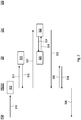
Figur 2 zeigt einen schematischen Prozessablauf eines erfindungsgemäßen Verfahrens gemäß einer ersten Ausführungsvariante. -
Figur 3 zeigt einen schematischen Prozessablauf eines erfindungsgemäßen Verfahrens gemäß einer zweiten Ausführungsvariante mit anwendungsspezifischen Pseudo-Authentisierungsobjekten. -
Figur 1 zeigt in stark schematisierter Blockdarstellung eine erfindungsgemäße Prozessorchipkarte oder Smartcard SC, im folgenden kurz als "Chipkarte" bezeichnet. Die Chipkarte SC ist als physikalische Einheit mit zwei in an sich bekannter Art und Weise integrierten Prozessoren oder Mikrokontrollern ausgebildet und umfasst einen (bspw. für kryptographische Anwendungen üblichen) sicheren Mikrocontroller MC und zusätzlich einen weiteren Mikrocontroller oder Zwischenchip 10, auch Proxy genannt. - Die beiden Mikrocontroller MC und 10 sind mittels einer nicht näher bezeichneten Datenleitung verbunden, die auf eine sichere Datenverbindung, insbesondere im Sinne der ISO-Norm 7816, Stand 1. November 2016, ausgelegt sein kann.
- Die Chipkarte SC umfasst des weiteren ein Koppelelement 12 zur kontaktlosen Datenübertragung mit einem externen Terminal oder Lesegerät 14 (PCD: Proximity Coupling Device), bspw. für eine Funkverbindung gemäß der ISO-Norm 14443 vom März 2016. Das Koppelelement 12 ist in dem dargestellten Ausführungsbeispiel mit dem Zwischenchip oder Proxy 10 verbunden.
- Die erfindungsgemäße Chipkarte SC kann des weiteren ein oder mehrere Eingabeelemente umfassen. In dem dargestellten Ausführungsbeispiel sind dies ein als Fingerabdrucksensor ausgebildetes erstes Eingabeelement 16 und ein als sogenanntes "PIN-Pad" ausgebildetes zweites Eingabeelement 18. Das bzw. die Eingabeelemente können - wie dargestellt - mit dem Zwischenchip oder Proxy 10 verbunden sein.
- Erfindungsgemäß umfasst die Chipkarte SC wenigstens zwei Anwendungen CA1 und CA2. Unter einer "Anwendung" ist im Kontext dieser Erfindung ein Programm für eine konkrete Nutzungsanwendung der Chipkarte zu verstehen. Es handelt sich hierbei um Daten, Kommandos, Abläufe, Mechanismen, Algorithmen und Programmcode in der Chipkarte, um diese im Rahmen eines bestimmten Systems zu betreiben. Bei derartigen Anwendungen kann es sich, wie eingangs bereits erwähnt, um das Bereitstellen eines logischen und/oder physischen Zutritts, die Entschlüsselung und/oder das Signieren elektronischer Post bzw. elektronischer Dokumente, eine Bezahlfunktion u.a.m. handeln. Anwendungen werden geläufigerweise auch als "Applets" bezeichnet.
- Selbstverständlich kann eine Chipkarte mehr als die beispielhaft beschriebenen zwei Anwendungen umfassen. Die erwähnte "GoID"-Karte bspw. umfasst im wesentlichen vier unterschiedliche Anwendungen, nämlich die Gewährung eines logischen Zutritts (bspw. bei einer Anmeldung zu einem Computerprogramm), die Gewährung eines physischen Zutritts (bspw. in ein Firmengelände oder ein Labor), zum Signieren von E-Mails und zum verschlüsseln/Entschlüsseln von E-Mails. Bei zunehmender Verbreitung von sogenannten multifunktionalen Chipkarten ist auch eine zunehmende Anzahl von Anwendungen auf einer Karte zu erwarten. Des weiteren können selbstverständlich auch zwei oder mehr verschiedene Anwendungen in einem Programm realisiert sein. Im Sinne der vorliegenden Erfindung stellt somit auch eine Nutzungsmöglichkeit eines Programms eine Anwendung dar, mit der Folge, dass zwei oder mehr Nutzungsmöglichkeiten eines Programms als die mindestens zwei Anwendungen der Erfindung zu verstehen sind.
- Des weiteren umfasst die Chipkarte SC erfindungsgemäß eine Signalanzeige 20. Dabei kann es sich um ein akustisches und/oder optisches Anzeigeelement wie bspw. eine LED o.dgl. handeln. In dem dargestellten Ausführungsbeispiel umfasst die Chipkarte SC noch ein zusätzliches Ausgabeelement 22 wie bspw. eine Anzeigeeinheit. Die Signalanzeige 20 und das Ausgabeelement 22 sind in dem dargestellten Ausführungsbeispiel mit dem Zwischenchip oder Proxy 10 verbunden. In anderer Ausgestaltung der Erfindung kann die Chipkarte mehrere Signalanzeigen umfassen, bspw. eine Signalanzeige pro Anwendung, so dass jeder Anwendung eine eigene Signalanzeige, wie bspw. eine jeweils anders farbige LED, zugeordnet ist. In dem nachstehend beschriebenen Ausführungsbeispiel ist die Signalanzeige 20 so ausgestaltet, dass sie zwei unterschiedliche Signale entsprechend den beiden Anwendungen CA1 bzw. CA2 ausgeben kann.
- Die Chipkarte SC umfasst außerdem einen erfindungsgemäßen Berechtigungsverwalter CM (CM: Credential Manager), der in dem dargestellten Ausführungsbeispiel auf dem sicheren Mikrocontroller MC ausgebildet ist. Andere Ausgestaltungen sind möglich und erschließen sich dem Fachmann ohne weiteres.
- Der Berechtigungsverwalter CM ist mit den beiden Anwendungen CA1, CA2 verbunden. Die beiden Anwendungen CA1, CA2 sind in dem dargestellten Ausführungsbeispiel auf dem sicheren Mikrocontroller MC ausgebildet. Der Proxy 10 ist mit den Anwendungen CA1, CA2 zumindest indirekt verbunden. Andere Ausgestaltungen sind möglich und erschließen sich dem Fachmann ohne weiteres.
- Im Betrieb der erfindungsgemäßen Prozessorchipkarte SC wie in
Figur 2 schematisch dargestellt erhält der Proxy 10 über die kontaktlose Schnittstelle RF/12 von dem Lesegerät 14/PCD bei S10 eine Anfrage, eine Sicherheitsoperation gemäß der ersten Anwendung CA1 (client applet 1) auszuführen. Daraufhin veranlasst der Proxy 10 bei S12, dass über die Signalanzeige 20 das der angefragten ersten Anwendung CA1 zugeordnete Signal angezeigt wird. - Der Proxy 10 wartet dann auf eine Bestätigung durch den Nutzer, dass er eine Ausführung der über die Signalanzeige 20 angezeigten Anwendung CA1 wünscht. Dies kann bspw. durch Eingabe einer Kennung (bspw. auf der Karte), wie einer PIN o.dgl., erfolgen, auf deren Grundlage auch eine Authentisierung des Nutzers vorgenommen werden kann, oder alternativ durch eine separate direkte Bestätigung.
- In dem dargestellten Ausführungsbeispiel leitet der Proxy 10 bei S14 die empfangene PIN zur Überprüfung an den Berechtigungsverwalter CM weiter. Bei S16 prüft der Berechtigungsverwalter CM die PIN und gibt bei S18 eine positive Rückmeldung an den Proxy 10. Damit ist der Authentisierungsstatus der PIN kartenintern auf "TRUE" gesetzt. Erfindungsgemäß wird somit in einem Gang die angezeigte Anwendung die Nutzer-Authentisierung initiiert.
- Als Folge sendet der Proxy 10 bei S20 einen Ausführungsbefehl an die erste Anwendung CA1. Die Anwendung CA1 erzeugt in Reaktion auf diesen Ausführungsbefehl bei S22 eine Anfrage zum Authentisierungsstatus der PIN und sendet diese Anfrage bei S24 an den Berechtigungsverwalter CM. Der Berechtigungsverwalter CM fragt bei S26 den Authentisierungsstatus der PIN ab und sendet bei S28 das Ergebnis der Abfrage/Überprüfung (Okay/TRUE) an die Anwendung CA1, die damit (zumindest implizit) freigegeben ist und daraufhin die Ausführung startet.
- Nach erfolgter Ausführung der Anwendung CA1 wird bei S30 das Ausführungsergebnis von der Anwendung CA1 an den Proxy 10 übermittelt. In Reaktion auf das erhaltene Ergebnis übermittelt der Proxy 10 bei S32 einen De-Authentisierungsbefehl an den Berechtigungsverwalter CM, der daraufhin den Authentisierungsstatus der PIN auf "nicht gesetzt" bzw. "FALSE" setzt und bei S34 das entsprechende Okay als Bestätigung an den Proxy 10 sendet, was wiederum den Proxy 10 dazu veranlasst, das Ergebnis der Anwendungsausführung bei S36 an das Lesegerät/Terminal PCD zu senden (wenn es sich bspw. um die Einräumung eines physischen Zutritts durch ein Gatter oder eine Tür handelt, bestünde das Ergebnis der Anwendung CA1 in der Feststellung, dass der authentisierte Nutzer zugangsberechtigt ist und das Gatter bezieht wie die Türe zu öffnen ist, und das Terminal erhielte von der Chipkarte (d.h. von deren Proxy) einen Türöffnungsbefehl).
- Zusammengefasst stellen sich die Ablaufschritte wie folgt dar:
- S10
- Anfrage von PCD an Proxy, CA1 auszuführen
- S12
- Anzeige CA1 auf Signalanzeige, warten auf PIN
- S14
- Befehl an CM, prüfe PIN
- S16
- PIN-Prüfung
- S18
- PIN OK, Authentisierung erfolgt, Status "TRUE"
- S20
- Ausführungsbefehl von Proxy an CA1
- S22
- Anfrage Authentisierungsstatus durch CA1
- S24
- Senden Anfrage an CM
- S26
- Abfrage Authentisierungsstatus in CM
- S28
- Senden Authentisierungsstatus an CA1
- S30
- Ergebnis CA1 an Proxy
- S32
- Befehl De-Authentisierung der PIN an CM
- S34
- De-Authentisierung Okay
- S36
- Ausgabe Ergebnis an PCD
-
Figur 3 veranschaulicht in schematischer Weise einen entsprechenden Ablauf für eine Ausführungsvariante, bei der so genannte anwendungsspezifische Pseudo-Authentisierungsobjekte vorgesehen sind. - In dem dargestellten Ausführungsbeispiel mit zwei unterschiedlichen Anwendungen CA1 und CA2 und einer PIN als Nutzerkennung zur Authentisierung ist kartenintern (bspw. in dem Berechtigungsverwalter CM) jeder der beiden Anwendungen CA1 und CA2 jeweils eine sogenannte Pseudo-PIN pPIN1 bzw. pPIN2 zugeordnet (wie bereits voranstehend beschrieben, ist der Berechtigungsverwalter dann so konfiguriert, dass er bei Eingabe einer Kennung in Reaktion auf eine über die Signalanzeige wiedergegebene Anwendung intern mit der dieser Anwendung zugeordneten Pseudo-Kennung arbeitet und diese nach Eingabe der Kennung durch den Nutzer und positiver Kennungsprüfung (also erfolgter Authentisierung) auf "True" setzt). Der Berechtigungsverwalter CM ist gemäß dieser Ausführungsvariante so konfiguriert, dass ein Authentisierungsstatus nicht im Zusammenhang mit der Nutzer-PIN gesetzt wird, sondern für die internen Pseudo-PINS pPIN1 und pPIN2.
- Im Betrieb der erfindungsgemäßen Prozessorchipkarte SC gemäß der Ausführungsvariante der
Figur 3 erhält der Proxy 10 über die kontaktlose Schnittstelle RF/12 von dem Lesegerät 14/PCD bei S50 eine Anfrage, eine Sicherheitsoperation gemäß der ersten Anwendung CA1 (client applet 1) auszuführen. Daraufhin veranlasst der Proxy 10 bei S52, dass über die Signalanzeige 20 das der angefragten ersten Anwendung CA1 zugeordnete Signal angezeigt wird. - Der Proxy 10 wartet dann auf eine Bestätigung durch den Nutzer, dass er eine Ausführung der über die Signalanzeige 20 angezeigten Anwendung CA1 wünscht. Dies erfolgt wie bereits im Zusammenhang mit dem Ausführungsbeispiel der
Figur 2 geschrieben durch Eingabe einer Kennung (bspw. auf der Karte), wie einer PIN o.dgl., auf deren Grundlage auch eine Authentisierung des Nutzers vorgenommen werden kann. - Nach Empfang der PIN leitet der Proxy 10 bei S54 die empfangene PIN zur Überprüfung an den Berechtigungsverwalter CM für die konkrete Anwendung CA1 weiter, so dass der Berechtigungsverwalter CM bei S56 die eingegebene Nutzer-PIN mit der der angefragten Anwendung CA1 zugeordneten Pseudo-PIN pPIN1 überprüft. Bei positiver Prüfung der Nutzer-PIN (und damit einhergehende Authentisierung) setzt der Berechtigungsverwalter CM den Authentisierungsstatus der Pseudo-PIN pPIN1 auf "TRUE" und sendet bei S58 eine positive Rückmeldung an den Proxy 10.
- Als Folge sendet der Proxy 10 bei S60 einen Ausführungsbefehl an die erste Anwendung CA1. Die Anwendung CA1 erzeugt in Reaktion auf diesen Ausführungsbefehl bei S62 eine Anfrage zum Authentisierungsstatus "ihrer" Pseudo-PIN pPIN1 und sendet diese Anfrage bei S64 an den Berechtigungsverwalter CM. Der Berechtigungsverwalter CM fragt bei S66 den Authentisierungsstatus der pPIN1 ab und sendet bei S68 das Ergebnis der Abfrage (Okay/TRUE) an die Anwendung CA1, die damit (zumindest implizit) freigegeben ist und daraufhin die Ausführung startet.
- Nach erfolgreicher Ausführung der Anwendung CA1 wird bei S70 das Ausführungsergebnis von der Anwendung CA1 über den Proxy 10 direkt (an das Lesegerät PCD) ausgegeben. Damit weicht der Ablauf von dem voranstehend in Zusammenhang mit dem Ausführungsbeispiel der
Figur 2 beschriebenen Ablauf ab: dort wird das Ergebnis zunächst intern an den Proxy 10 übermittelt, der daraufhin die De-Authentisierung der PIN beim Berechtigungsverwalter CM veranlasst. Erst dann wird in dem Ausgangsbeispiel derFigur 2 das Ergebnis "nach außen" gegeben. In dem vorliegenden Ausführungsbeispiel ist jedoch durch die Verwendung der internen Pseudo-Authentisierungsobjekte pPIN1 und pPIN2 sichergestellt, dass nur dasjenige Pseudo-Authentisierungsobjekt einen positiven Authentisierungsstatus hat, das der gewünschten Anwendung zugeordnet ist, während das bzw. die verbleibenden Pseudo-Authentisierungsobjekte nicht gesetzt sind. Auf die "Vorsichtsmaßnahme" der vorausgehenden De-Authentisierung kann somit verzichtet werden, so dass wie beschrieben das Anwendungsergebnis direkt ausgegeben werden kann. - Dies ist in der
Figur 3 beispielhaft mit den Schritten S80 bis S90 veranschaulicht: von dem Lesegerät PCD wird bei S80 (missbräuchlich) eine Anfrage zur Durchführung der zweiten Anwendung CA2 direkt an die Anwendung CA2 gesandt. Wie bei jeder Anfrage erzeugt die Anwendung CA2 in Reaktion hierauf eine Anfrage zum Authentisierungsstatus "ihrer" Pseudo-PIN, also der pPIN2, und sendet diese Anfrage bei S84 an den Berechtigungsverwalter CM. Der Berechtigungsverwalter CM fragt bei S86 den Authentisierungsstatus der pPIN2 ab und sendet bei S88 das Ergebnis der Abfrage ("FALSE"/nicht authentisiert) an die Anwendung CA2, die damit nicht freigegeben ist und keine Ausführung startet. Vielmehr sendet die Anwendung CA2 bei S90 eine Nichtausführungsnachricht (wie bspw. Sicherheitsstatus nicht erfüllt/security status not satisfied) an das Lesegerät PCD. - Zusammengefasst stellen sich die Ablaufschritte wie folgt dar:
- S50
- Anfrage von PCD an Proxy, CA1 auszuführen
- S52
- Anzeige CA1 auf Signalanzeige, warten auf PIN
- S54
- Befehl an CM, prüfe PIN für CA1 (mit pPIN1)
- S56
- Prüfung PIN mit pPIN1
- S58
- PIN OK => Pseudo-PIN-Status "TRUE"
- S60
- Ausführungsbefehl von Proxy an CA1
- S62
- Anfrage zum Authentisierungsstatus durch CA1
- S64
- Senden Anfrage an CM
- S66
- Abfrage Authentisierungsstatus in CM
- S68
- Senden Authentisierungsstatus an CA1
- S70
- Ergebnis CA1 an PCD
- S80
- Ausführungsbefehl von PCD an CA2
- S82
- Abfrage Authentisierungsstatus in CM
- S84
- Senden Anfrage an CM
- S86
- Abfrage Authentisierungsstatus in CM
- S88
- Senden Authentisierungsstatus an CA2
- S90
- Ausführungsverweigerung an PCD
- Dem Fachmann erschließen sich gegebenenfalls noch weitere Möglichkeiten, wie kartenintern sichergestellt werden kann, dass lediglich die Anwendung zur Ausführung kommt, die bei Eingabe der Nutzer-Kennung über die Signalanzeige angezeigt wird. Bspw. kann dies auch mittels einer APDU-Filterung im Zusammenspiel mit einer Whitelist, die nur bestimmte sichere Anwendungen zulässt, erfolgen (APDU: application protocol data unit; bezeichnet den softwaretechnischen Datencontainer, in dem die Daten einer Anwendung verpackt werden, um sie zwischen dem Lesegerät/Terminal und der Chipkarte auszutauschen). Alternativ kann auch eine Bindung an eine einzelne APDU zur Einmal-Authentisierung erfolgen.
- In einer weiteren Ausführung könnte die Eingabe auf der Karte auch nur eine Autorisierung anstatt einer Authentisierung sein. Der Nutzer sieht also, wofür die Karte benutzt werden soll, die Anwendung fordert aber keine explizite Authentisierung, der Nutzer erkennt dann dennoch (bspw. mittels LED), welche Transaktion durchgeführt werden soll, und bestätigt diese mittels einer Art "Confirm"-Taste/Enter-Taste.
- Wie eingangs bereits erwähnt, kann gemäß einer weiteren Ausführung eine einzelne Nutzungsmöglichkeit einer Anwendung CAx signalisiert werden.
- Die Erfindung verhindert somit einen Missbrauch von Anwendungen auf multifunktionalen Chipkarten, indem eine missbräuchliche Ausführung einer vom Nutzer nicht gewünschten Anwendung verhindert wird. Die nicht ausgewählte Anwendung ist somit (temporär) gesperrt. Der Nutzer kann sicher gehen, dass seine getätigten Nutzerauthentisierung im Zusammenhang mit einer bestimmten Anwendung nur für diese genutzt wird und nicht für andere Anwendungen missbraucht wird. Es handelt sich um eine anwendungsgebundene Nutzerauthentisierung mittels Feedback über eine Signalanzeige bei multifunktionalen Chipkarten.
Claims (14)
- Prozessorchipkarte (SC) mit- mindestens einem Mikrocontroller (MC, 10),- mindestens zwei Anwendungen (CA1, CA2),- mindestens einer Signalanzeige (20) und- einem Berechtigungsverwalter (CM),wobei die Prozessorchipkarte (SC) dazu konfiguriert ist,- mittels der mindestens einen Signalanzeige (20) anzuzeigen, welche der mindestens zwei Anwendungen (CA1, CA2) zur Ausführung vorgesehen ist, und- nach Empfang einer Bestätigung der zur Ausführung vorgesehenen Anwendung (CA1, CA2) die Anwendung (CA1, CA2) zur Ausführung freizugeben,wobei nach Freigabe der zur Ausführung vorgesehenen Anwendung (CA1, CA2) die mindestens eine verbleibende nicht ausgewählte Anwendung nicht ausgeführt werden kann.
- Prozessorchipkarte (SC) nach Anspruch 1, bei der die Bestätigung ein Einlesen einer Kennung, bspw. einer Nutzerkennung und/oder biometrischen Kennung, umfasst; und/oder
deren Berechtigungsverwalter (CM) auf dem mindestens einen Mikrocontroller (MC, 10) ausgebildet ist; und/oder
die als ersten Mikrocontroller einen sicheren Mikrocontroller (MC) und als zweiten Mikrocontroller einen mit dem sicheren Mikrocontroller (MC) verbundenen Zwischenchip (10) umfasst; und/oder
bei der jeder der mindestens zwei Anwendungen (CA1, CA2) ein anwendungsspezifisches Pseudo-Authentisierungsobjekt zugeordnet ist. - Verfahren zum Betrieb einer Prozessorchipkarte (SC), die mindestens zwei Anwendungen (CA1, CA2) aufweist, wobei eine Auswahl einer zur Ausführung vorgesehenen Anwendung (CA1, CA2) der mindestens zwei Anwendungen (CA1, CA2) über eine Signalanzeige (20) der Prozessorchipkarte (SC) angezeigt und nach Empfang einer Bestätigung der zur Ausführung vorgesehenen Anwendung (CA1, CA2) die Anwendung (CA1, CA2) zur Ausführung freigegeben wird, wobei nach Freigabe der zur Ausführung vorgesehenen Anwendung (CA1, CA2) die mindestens eine verbleibende nicht ausgewählte Anwendung nicht ausgeführt werden kann.
- Verfahren nach Anspruch 6, bei dem die Bestätigung ein Einlesen einer Kennung, bspw. einer Nutzererkennung und/oder biometrischen Kennung, umfasst; und/oder bei dem die Bestätigung eine Authentisierung umfasst.
- Verfahren nach einem der Ansprüche 3 oder 4, mit den folgenden Schritten:- Empfangen einer Auswahl einer der mindestens zwei Anwendungen (CA1, CA2),- Anzeigen der zur Ausführung vorgesehenen Anwendung (CA1, CA2) über die Signalanzeige (20),- Empfangen einer Bestätigung des Nutzers,- Freigeben der bestätigten Anwendung zur Ausführung,- Ausgeben des Ergebnisses der ausgeführten Anwendung.
- Verfahren nach einem der Ansprüche 3 bis 5, das vor der Freigabe der bestätigten Anwendung zur Ausführung den Schritt des Überprüfens der Bestätigung umfasst.
- Verfahren nach Anspruch 6, bei dem der Berechtigungsverwalter (CM) bei positiver Überprüfung der Bestätigung einen Authentisierungsstatus auf "True" setzt.
- Verfahren nach einem der Ansprüche 3 bis 7, bei dem jeder der mindestens zwei Anwendungen (CA1, CA2) ein anwendungsspezifisches Pseudo-Authentisierungsobjekt zugeordnet ist.
- Verfahren nach Anspruch 8, bei dem der Berechtigungsverwalter (CM) bei Eingabe einer Kennung in Reaktion auf eine über die Signalanzeige (20) wiedergegebene Anwendung (CA1, CA2) eine dieser Anwendung zugeordnete Pseudo-Kennung nach positiver Kennungsprüfung auf "True" setzt.
- Verfahren nach einem der Ansprüche 3 bis 9, bei dem eine Anwendung (CA1, CA2) vor Durchführen eines Ausführungsbefehls bei dem Berechtigungsverwalter (CM) einen Authentisierungsstatus abfragt.
- Verfahren zum Betrieb einer Prozessorchipkarte (SC), die mindestens zwei Anwendungen (CA1, CA2) aufweist, wobei eine zur Ausführung vorgesehene Anwendung (CA1, CA2) über eine Signalanzeige (20) der Prozessorchipkarte (SC) angezeigt wird, mit den folgenden Schritten:- Empfangen einer Anfrage zur Ausführung einer der mindestens zwei Anwendungen (CA1, CA2),- Anzeigen der zur Ausführung vorgesehenen Anwendung (CA1, CA2) über die Signalanzeige (20),- Empfangen einer Kennung,- Überprüfen der Kennung durch einen Berechtigungsverwalter (CM) der Prozessorchipkarte (SC),- bei positiver Überprüfung, Setzen eines Authentisierungsstatus durch den Berechtigungsverwalter (CM),- Freigeben der bestätigten Anwendung zur Ausführung,wobei nach Freigabe der zur Ausführung vorgesehenen Anwendung (CA1, CA2) die mindestens eine verbleibende nicht ausgewählte Anwendung nicht ausgeführt werden kann.
- Verfahren nach Anspruch 11, das vor dem Schritt des Freigebens den folgenden weiteren Schritt umfasst:- Abfrage des Authentisierungsstatus durch die zur Ausführung vorgesehene Anwendung (CA1, CA2) bei dem Berechtigungsverwalter (CM),- Freigabe der Anwendung (CA1, CA2) bei positivem Authentisierungsstatus, andernfalls Ausführungsverweigerung.
- Verfahren nach Anspruch 11 oder 12, bei dem der Authentisierungsstatus der Nutzerkennung gesetzt wird oder bei dem der Authentisierungsstatus einer durch die Nutzerkennung referenzierten und einer Anwendung zugeordneten Pseudo-Kennung gesetzt wird.
- Computerprogramm mit Programmcodemitteln, um alle Schritte eines Verfahrens nach einem der Ansprüche 3 bis 13 durchzuführen, wenn das Computerprogramm auf einer Prozessorchipkarte (SC) ausgeführt wird.
Applications Claiming Priority (1)
| Application Number | Priority Date | Filing Date | Title |
|---|---|---|---|
| DE102017223509.8A DE102017223509A1 (de) | 2017-12-21 | 2017-12-21 | Prozessorchipkarte und ein Verfahren zu deren Betrieb |
Publications (2)
| Publication Number | Publication Date |
|---|---|
| EP3502971A1 true EP3502971A1 (de) | 2019-06-26 |
| EP3502971B1 EP3502971B1 (de) | 2020-11-18 |
Family
ID=64959149
Family Applications (1)
| Application Number | Title | Priority Date | Filing Date |
|---|---|---|---|
| EP18214309.9A Active EP3502971B1 (de) | 2017-12-21 | 2018-12-20 | Prozessorchipkarte und ein verfahren zu deren betrieb |
Country Status (2)
| Country | Link |
|---|---|
| EP (1) | EP3502971B1 (de) |
| DE (1) | DE102017223509A1 (de) |
Citations (5)
| Publication number | Priority date | Publication date | Assignee | Title |
|---|---|---|---|---|
| DE202010006698U1 (de) * | 2009-05-13 | 2010-08-26 | Lorenzen, Karsten | Chipkarte mit optischer Meldefunktion |
| US20150262052A1 (en) * | 2014-03-14 | 2015-09-17 | Ebay Inc. | Omni smart card |
| US9230255B1 (en) * | 2014-08-15 | 2016-01-05 | Mastercard International Incorporated | Payment card having light-emitting diode indicators coordinated with stored payment applications |
| EP3009966A1 (de) * | 2005-02-17 | 2016-04-20 | Koninklijke Philips N.V. | Chipkarte und verfahren zum betrieb einer chipkarte |
| EP3214583A2 (de) * | 2016-03-04 | 2017-09-06 | Bundesdruckerei GmbH | Wert- oder sicherheitsdokument mit einem sensor zum erfassen einer nutzerinteraktion und einer elektronischen schaltung |
Family Cites Families (2)
| Publication number | Priority date | Publication date | Assignee | Title |
|---|---|---|---|---|
| DE19610070A1 (de) | 1996-03-14 | 1997-09-18 | Siemens Ag | Chipkarte |
| DE19839041C2 (de) | 1998-08-28 | 2003-03-27 | Ibm | Verfahren zum Identifizieren und Darstellen von Zuständen eines Fehlbedienungszählers |
-
2017
- 2017-12-21 DE DE102017223509.8A patent/DE102017223509A1/de not_active Withdrawn
-
2018
- 2018-12-20 EP EP18214309.9A patent/EP3502971B1/de active Active
Patent Citations (5)
| Publication number | Priority date | Publication date | Assignee | Title |
|---|---|---|---|---|
| EP3009966A1 (de) * | 2005-02-17 | 2016-04-20 | Koninklijke Philips N.V. | Chipkarte und verfahren zum betrieb einer chipkarte |
| DE202010006698U1 (de) * | 2009-05-13 | 2010-08-26 | Lorenzen, Karsten | Chipkarte mit optischer Meldefunktion |
| US20150262052A1 (en) * | 2014-03-14 | 2015-09-17 | Ebay Inc. | Omni smart card |
| US9230255B1 (en) * | 2014-08-15 | 2016-01-05 | Mastercard International Incorporated | Payment card having light-emitting diode indicators coordinated with stored payment applications |
| EP3214583A2 (de) * | 2016-03-04 | 2017-09-06 | Bundesdruckerei GmbH | Wert- oder sicherheitsdokument mit einem sensor zum erfassen einer nutzerinteraktion und einer elektronischen schaltung |
Also Published As
| Publication number | Publication date |
|---|---|
| EP3502971B1 (de) | 2020-11-18 |
| DE102017223509A1 (de) | 2019-06-27 |
Similar Documents
| Publication | Publication Date | Title |
|---|---|---|
| EP2454704B1 (de) | Verfahren zum lesen von attributen aus einem id-token | |
| EP3731119B1 (de) | Computerimplementiertes verfahren zur zugriffskontrolle | |
| EP3261011B1 (de) | Verfahren zum lesen von attributen aus einem id-token | |
| EP2769330B1 (de) | Verfahren zum aufruf eines client-programms | |
| EP2415228B1 (de) | Verfahren zum lesen von attributen aus einem id-token über eine mobilfunkverbindung | |
| EP3699791B1 (de) | Zugangskontrolle mit einem mobilfunkgerät | |
| EP3748521B1 (de) | Verfahren zum lesen von attributen aus einem id-token | |
| EP2602738A2 (de) | Vorrichtung zum Schutz von Sicherheitstoken gegen Malware | |
| WO2013056783A1 (de) | Mobiles endgerät, transaktionsterminal und verfahren zur durchführung einer transaktion an einem transaktionsterminal mittels eines mobilen endgeräts | |
| EP3254432B1 (de) | Verfahren zur berechtigungsverwaltung in einer anordnung mit mehreren rechensystemen | |
| EP2996299B1 (de) | Verfahren und Anordnung zur Autorisierung einer Aktion an einem Selbstbedienungssystem | |
| EP3319003A1 (de) | Verfahren und system zur authentifizierung eines mobilen telekommunikationsendgeräts an einem dienst-computersystem und mobiles telekommunikationsendgerät | |
| EP2752785B1 (de) | Verfahren zur Personalisierung eines Secure Elements (SE) und Computersystem | |
| EP2916252B1 (de) | Elektronisches Transaktionsverfahren und Computersystem | |
| EP3657750B1 (de) | Verfahren zur authentifizierung einer datenbrille in einem datennetz | |
| EP3244331B1 (de) | Verfahren zum lesen von attributen aus einem id-token | |
| EP3502971B1 (de) | Prozessorchipkarte und ein verfahren zu deren betrieb | |
| EP2169579B1 (de) | Verfahren und Vorrichtung zum Zugriff auf ein maschinenlesbares Dokument | |
| EP3298526B1 (de) | Verfahren zum lesen von attributen aus einem id-token | |
| EP2893483B1 (de) | Verfahren zur personalisierung eines secure elements (se) und computersystem | |
| EP3283999B1 (de) | Elektronisches system zur erzeugung eines zertifikats | |
| EP1365363B1 (de) | Verfahren zur Ausführung einer Datentransaktion mittels einer aus einer Haupt- und einer trennbaren Hilfskomponente bestehenden Transaktionsvorrichtung | |
| EP3361436B1 (de) | Verfahren zur freigabe einer transaktion | |
| EP2840757B1 (de) | Individuelle zentrale verwaltung von chipkarten | |
| DE102013022448B3 (de) | Elektronisches Transaktionsverfahren und Computersystem |
Legal Events
| Date | Code | Title | Description |
|---|---|---|---|
| PUAI | Public reference made under article 153(3) epc to a published international application that has entered the european phase |
Free format text: ORIGINAL CODE: 0009012 |
|
| STAA | Information on the status of an ep patent application or granted ep patent |
Free format text: STATUS: THE APPLICATION HAS BEEN PUBLISHED |
|
| AK | Designated contracting states |
Kind code of ref document: A1 Designated state(s): AL AT BE BG CH CY CZ DE DK EE ES FI FR GB GR HR HU IE IS IT LI LT LU LV MC MK MT NL NO PL PT RO RS SE SI SK SM TR |
|
| AX | Request for extension of the european patent |
Extension state: BA ME |
|
| STAA | Information on the status of an ep patent application or granted ep patent |
Free format text: STATUS: REQUEST FOR EXAMINATION WAS MADE |
|
| 17P | Request for examination filed |
Effective date: 20191108 |
|
| RBV | Designated contracting states (corrected) |
Designated state(s): AL AT BE BG CH CY CZ DE DK EE ES FI FR GB GR HR HU IE IS IT LI LT LU LV MC MK MT NL NO PL PT RO RS SE SI SK SM TR |
|
| STAA | Information on the status of an ep patent application or granted ep patent |
Free format text: STATUS: EXAMINATION IS IN PROGRESS |
|
| 17Q | First examination report despatched |
Effective date: 20200615 |
|
| GRAP | Despatch of communication of intention to grant a patent |
Free format text: ORIGINAL CODE: EPIDOSNIGR1 |
|
| STAA | Information on the status of an ep patent application or granted ep patent |
Free format text: STATUS: GRANT OF PATENT IS INTENDED |
|
| INTG | Intention to grant announced |
Effective date: 20200723 |
|
| RIN1 | Information on inventor provided before grant (corrected) |
Inventor name: KRAUS, MICHA Inventor name: BASTIAN, PAUL |
|
| GRAS | Grant fee paid |
Free format text: ORIGINAL CODE: EPIDOSNIGR3 |
|
| GRAA | (expected) grant |
Free format text: ORIGINAL CODE: 0009210 |
|
| STAA | Information on the status of an ep patent application or granted ep patent |
Free format text: STATUS: THE PATENT HAS BEEN GRANTED |
|
| AK | Designated contracting states |
Kind code of ref document: B1 Designated state(s): AL AT BE BG CH CY CZ DE DK EE ES FI FR GB GR HR HU IE IS IT LI LT LU LV MC MK MT NL NO PL PT RO RS SE SI SK SM TR |
|
| REG | Reference to a national code |
Ref country code: GB Ref legal event code: FG4D Free format text: NOT ENGLISH |
|
| REG | Reference to a national code |
Ref country code: CH Ref legal event code: NV Representative=s name: VALIPAT S.A. C/O BOVARD SA NEUCHATEL, CH Ref country code: CH Ref legal event code: EP |
|
| REG | Reference to a national code |
Ref country code: DE Ref legal event code: R096 Ref document number: 502018003044 Country of ref document: DE |
|
| REG | Reference to a national code |
Ref country code: IE Ref legal event code: FG4D Free format text: LANGUAGE OF EP DOCUMENT: GERMAN |
|
| REG | Reference to a national code |
Ref country code: AT Ref legal event code: REF Ref document number: 1336575 Country of ref document: AT Kind code of ref document: T Effective date: 20201215 |
|
| REG | Reference to a national code |
Ref country code: NL Ref legal event code: FP |
|
| PG25 | Lapsed in a contracting state [announced via postgrant information from national office to epo] |
Ref country code: RS Free format text: LAPSE BECAUSE OF FAILURE TO SUBMIT A TRANSLATION OF THE DESCRIPTION OR TO PAY THE FEE WITHIN THE PRESCRIBED TIME-LIMIT Effective date: 20201118 Ref country code: PT Free format text: LAPSE BECAUSE OF FAILURE TO SUBMIT A TRANSLATION OF THE DESCRIPTION OR TO PAY THE FEE WITHIN THE PRESCRIBED TIME-LIMIT Effective date: 20210318 Ref country code: FI Free format text: LAPSE BECAUSE OF FAILURE TO SUBMIT A TRANSLATION OF THE DESCRIPTION OR TO PAY THE FEE WITHIN THE PRESCRIBED TIME-LIMIT Effective date: 20201118 Ref country code: NO Free format text: LAPSE BECAUSE OF FAILURE TO SUBMIT A TRANSLATION OF THE DESCRIPTION OR TO PAY THE FEE WITHIN THE PRESCRIBED TIME-LIMIT Effective date: 20210218 Ref country code: GR Free format text: LAPSE BECAUSE OF FAILURE TO SUBMIT A TRANSLATION OF THE DESCRIPTION OR TO PAY THE FEE WITHIN THE PRESCRIBED TIME-LIMIT Effective date: 20210219 |
|
| PG25 | Lapsed in a contracting state [announced via postgrant information from national office to epo] |
Ref country code: BG Free format text: LAPSE BECAUSE OF FAILURE TO SUBMIT A TRANSLATION OF THE DESCRIPTION OR TO PAY THE FEE WITHIN THE PRESCRIBED TIME-LIMIT Effective date: 20210218 Ref country code: SE Free format text: LAPSE BECAUSE OF FAILURE TO SUBMIT A TRANSLATION OF THE DESCRIPTION OR TO PAY THE FEE WITHIN THE PRESCRIBED TIME-LIMIT Effective date: 20201118 Ref country code: LV Free format text: LAPSE BECAUSE OF FAILURE TO SUBMIT A TRANSLATION OF THE DESCRIPTION OR TO PAY THE FEE WITHIN THE PRESCRIBED TIME-LIMIT Effective date: 20201118 Ref country code: PL Free format text: LAPSE BECAUSE OF FAILURE TO SUBMIT A TRANSLATION OF THE DESCRIPTION OR TO PAY THE FEE WITHIN THE PRESCRIBED TIME-LIMIT Effective date: 20201118 Ref country code: IS Free format text: LAPSE BECAUSE OF FAILURE TO SUBMIT A TRANSLATION OF THE DESCRIPTION OR TO PAY THE FEE WITHIN THE PRESCRIBED TIME-LIMIT Effective date: 20210318 |
|
| REG | Reference to a national code |
Ref country code: LT Ref legal event code: MG9D |
|
| PG25 | Lapsed in a contracting state [announced via postgrant information from national office to epo] |
Ref country code: HR Free format text: LAPSE BECAUSE OF FAILURE TO SUBMIT A TRANSLATION OF THE DESCRIPTION OR TO PAY THE FEE WITHIN THE PRESCRIBED TIME-LIMIT Effective date: 20201118 |
|
| PG25 | Lapsed in a contracting state [announced via postgrant information from national office to epo] |
Ref country code: LT Free format text: LAPSE BECAUSE OF FAILURE TO SUBMIT A TRANSLATION OF THE DESCRIPTION OR TO PAY THE FEE WITHIN THE PRESCRIBED TIME-LIMIT Effective date: 20201118 Ref country code: RO Free format text: LAPSE BECAUSE OF FAILURE TO SUBMIT A TRANSLATION OF THE DESCRIPTION OR TO PAY THE FEE WITHIN THE PRESCRIBED TIME-LIMIT Effective date: 20201118 Ref country code: SM Free format text: LAPSE BECAUSE OF FAILURE TO SUBMIT A TRANSLATION OF THE DESCRIPTION OR TO PAY THE FEE WITHIN THE PRESCRIBED TIME-LIMIT Effective date: 20201118 Ref country code: SK Free format text: LAPSE BECAUSE OF FAILURE TO SUBMIT A TRANSLATION OF THE DESCRIPTION OR TO PAY THE FEE WITHIN THE PRESCRIBED TIME-LIMIT Effective date: 20201118 Ref country code: CZ Free format text: LAPSE BECAUSE OF FAILURE TO SUBMIT A TRANSLATION OF THE DESCRIPTION OR TO PAY THE FEE WITHIN THE PRESCRIBED TIME-LIMIT Effective date: 20201118 Ref country code: EE Free format text: LAPSE BECAUSE OF FAILURE TO SUBMIT A TRANSLATION OF THE DESCRIPTION OR TO PAY THE FEE WITHIN THE PRESCRIBED TIME-LIMIT Effective date: 20201118 |
|
| REG | Reference to a national code |
Ref country code: DE Ref legal event code: R097 Ref document number: 502018003044 Country of ref document: DE |
|
| PG25 | Lapsed in a contracting state [announced via postgrant information from national office to epo] |
Ref country code: MC Free format text: LAPSE BECAUSE OF FAILURE TO SUBMIT A TRANSLATION OF THE DESCRIPTION OR TO PAY THE FEE WITHIN THE PRESCRIBED TIME-LIMIT Effective date: 20201118 Ref country code: DK Free format text: LAPSE BECAUSE OF FAILURE TO SUBMIT A TRANSLATION OF THE DESCRIPTION OR TO PAY THE FEE WITHIN THE PRESCRIBED TIME-LIMIT Effective date: 20201118 |
|
| REG | Reference to a national code |
Ref country code: BE Ref legal event code: MM Effective date: 20201231 |
|
| PLBE | No opposition filed within time limit |
Free format text: ORIGINAL CODE: 0009261 |
|
| STAA | Information on the status of an ep patent application or granted ep patent |
Free format text: STATUS: NO OPPOSITION FILED WITHIN TIME LIMIT |
|
| 26N | No opposition filed |
Effective date: 20210819 |
|
| PG25 | Lapsed in a contracting state [announced via postgrant information from national office to epo] |
Ref country code: AL Free format text: LAPSE BECAUSE OF FAILURE TO SUBMIT A TRANSLATION OF THE DESCRIPTION OR TO PAY THE FEE WITHIN THE PRESCRIBED TIME-LIMIT Effective date: 20201118 Ref country code: IE Free format text: LAPSE BECAUSE OF NON-PAYMENT OF DUE FEES Effective date: 20201220 Ref country code: IT Free format text: LAPSE BECAUSE OF FAILURE TO SUBMIT A TRANSLATION OF THE DESCRIPTION OR TO PAY THE FEE WITHIN THE PRESCRIBED TIME-LIMIT Effective date: 20201118 Ref country code: LU Free format text: LAPSE BECAUSE OF NON-PAYMENT OF DUE FEES Effective date: 20201220 |
|
| PG25 | Lapsed in a contracting state [announced via postgrant information from national office to epo] |
Ref country code: SI Free format text: LAPSE BECAUSE OF FAILURE TO SUBMIT A TRANSLATION OF THE DESCRIPTION OR TO PAY THE FEE WITHIN THE PRESCRIBED TIME-LIMIT Effective date: 20201118 |
|
| PG25 | Lapsed in a contracting state [announced via postgrant information from national office to epo] |
Ref country code: ES Free format text: LAPSE BECAUSE OF FAILURE TO SUBMIT A TRANSLATION OF THE DESCRIPTION OR TO PAY THE FEE WITHIN THE PRESCRIBED TIME-LIMIT Effective date: 20201118 |
|
| PG25 | Lapsed in a contracting state [announced via postgrant information from national office to epo] |
Ref country code: IS Free format text: LAPSE BECAUSE OF FAILURE TO SUBMIT A TRANSLATION OF THE DESCRIPTION OR TO PAY THE FEE WITHIN THE PRESCRIBED TIME-LIMIT Effective date: 20210318 Ref country code: TR Free format text: LAPSE BECAUSE OF FAILURE TO SUBMIT A TRANSLATION OF THE DESCRIPTION OR TO PAY THE FEE WITHIN THE PRESCRIBED TIME-LIMIT Effective date: 20201118 Ref country code: MT Free format text: LAPSE BECAUSE OF FAILURE TO SUBMIT A TRANSLATION OF THE DESCRIPTION OR TO PAY THE FEE WITHIN THE PRESCRIBED TIME-LIMIT Effective date: 20201118 Ref country code: CY Free format text: LAPSE BECAUSE OF FAILURE TO SUBMIT A TRANSLATION OF THE DESCRIPTION OR TO PAY THE FEE WITHIN THE PRESCRIBED TIME-LIMIT Effective date: 20201118 |
|
| PG25 | Lapsed in a contracting state [announced via postgrant information from national office to epo] |
Ref country code: MK Free format text: LAPSE BECAUSE OF FAILURE TO SUBMIT A TRANSLATION OF THE DESCRIPTION OR TO PAY THE FEE WITHIN THE PRESCRIBED TIME-LIMIT Effective date: 20201118 |
|
| PG25 | Lapsed in a contracting state [announced via postgrant information from national office to epo] |
Ref country code: BE Free format text: LAPSE BECAUSE OF NON-PAYMENT OF DUE FEES Effective date: 20201231 |
|
| P01 | Opt-out of the competence of the unified patent court (upc) registered |
Effective date: 20230526 |
|
| REG | Reference to a national code |
Ref country code: CH Ref legal event code: U11 Free format text: ST27 STATUS EVENT CODE: U-0-0-U10-U11 (AS PROVIDED BY THE NATIONAL OFFICE) Effective date: 20260101 |
|
| PGFP | Annual fee paid to national office [announced via postgrant information from national office to epo] |
Ref country code: GB Payment date: 20251218 Year of fee payment: 8 |
|
| PGFP | Annual fee paid to national office [announced via postgrant information from national office to epo] |
Ref country code: AT Payment date: 20251215 Year of fee payment: 8 |
|
| PGFP | Annual fee paid to national office [announced via postgrant information from national office to epo] |
Ref country code: FR Payment date: 20251218 Year of fee payment: 8 Ref country code: NL Payment date: 20251217 Year of fee payment: 8 |
|
| PGFP | Annual fee paid to national office [announced via postgrant information from national office to epo] |
Ref country code: DE Payment date: 20251222 Year of fee payment: 8 |
|
| PGFP | Annual fee paid to national office [announced via postgrant information from national office to epo] |
Ref country code: CH Payment date: 20260101 Year of fee payment: 8 |