EP3502969A1 - Object provided with two-dimensional code, method for generating two-dimensional code, and recognition method and apparatus - Google Patents
Object provided with two-dimensional code, method for generating two-dimensional code, and recognition method and apparatus Download PDFInfo
- Publication number
- EP3502969A1 EP3502969A1 EP17841065.0A EP17841065A EP3502969A1 EP 3502969 A1 EP3502969 A1 EP 3502969A1 EP 17841065 A EP17841065 A EP 17841065A EP 3502969 A1 EP3502969 A1 EP 3502969A1
- Authority
- EP
- European Patent Office
- Prior art keywords
- data information
- location detection
- data
- dimensional code
- modules
- Prior art date
- Legal status (The legal status is an assumption and is not a legal conclusion. Google has not performed a legal analysis and makes no representation as to the accuracy of the status listed.)
- Granted
Links
Images









Classifications
-
- G—PHYSICS
- G06—COMPUTING OR CALCULATING; COUNTING
- G06K—GRAPHICAL DATA READING; PRESENTATION OF DATA; RECORD CARRIERS; HANDLING RECORD CARRIERS
- G06K19/00—Record carriers for use with machines and with at least a part designed to carry digital markings
- G06K19/06—Record carriers for use with machines and with at least a part designed to carry digital markings characterised by the kind of the digital marking, e.g. shape, nature, code
- G06K19/06009—Record carriers for use with machines and with at least a part designed to carry digital markings characterised by the kind of the digital marking, e.g. shape, nature, code with optically detectable marking
- G06K19/06037—Record carriers for use with machines and with at least a part designed to carry digital markings characterised by the kind of the digital marking, e.g. shape, nature, code with optically detectable marking multi-dimensional coding
-
- G—PHYSICS
- G06—COMPUTING OR CALCULATING; COUNTING
- G06K—GRAPHICAL DATA READING; PRESENTATION OF DATA; RECORD CARRIERS; HANDLING RECORD CARRIERS
- G06K19/00—Record carriers for use with machines and with at least a part designed to carry digital markings
- G06K19/06—Record carriers for use with machines and with at least a part designed to carry digital markings characterised by the kind of the digital marking, e.g. shape, nature, code
- G06K19/06009—Record carriers for use with machines and with at least a part designed to carry digital markings characterised by the kind of the digital marking, e.g. shape, nature, code with optically detectable marking
- G06K19/06046—Constructional details
-
- G—PHYSICS
- G06—COMPUTING OR CALCULATING; COUNTING
- G06K—GRAPHICAL DATA READING; PRESENTATION OF DATA; RECORD CARRIERS; HANDLING RECORD CARRIERS
- G06K7/00—Methods or arrangements for sensing record carriers, e.g. for reading patterns
- G06K7/10—Methods or arrangements for sensing record carriers, e.g. for reading patterns by electromagnetic radiation, e.g. optical sensing; by corpuscular radiation
- G06K7/14—Methods or arrangements for sensing record carriers, e.g. for reading patterns by electromagnetic radiation, e.g. optical sensing; by corpuscular radiation using light without selection of wavelength, e.g. sensing reflected white light
- G06K7/1404—Methods for optical code recognition
- G06K7/1408—Methods for optical code recognition the method being specifically adapted for the type of code
- G06K7/1417—2D bar codes
-
- G—PHYSICS
- G06—COMPUTING OR CALCULATING; COUNTING
- G06K—GRAPHICAL DATA READING; PRESENTATION OF DATA; RECORD CARRIERS; HANDLING RECORD CARRIERS
- G06K7/00—Methods or arrangements for sensing record carriers, e.g. for reading patterns
- G06K7/10—Methods or arrangements for sensing record carriers, e.g. for reading patterns by electromagnetic radiation, e.g. optical sensing; by corpuscular radiation
- G06K7/14—Methods or arrangements for sensing record carriers, e.g. for reading patterns by electromagnetic radiation, e.g. optical sensing; by corpuscular radiation using light without selection of wavelength, e.g. sensing reflected white light
- G06K7/1404—Methods for optical code recognition
- G06K7/146—Methods for optical code recognition the method including quality enhancement steps
- G06K7/1473—Methods for optical code recognition the method including quality enhancement steps error correction
-
- G—PHYSICS
- G06—COMPUTING OR CALCULATING; COUNTING
- G06K—GRAPHICAL DATA READING; PRESENTATION OF DATA; RECORD CARRIERS; HANDLING RECORD CARRIERS
- G06K19/00—Record carriers for use with machines and with at least a part designed to carry digital markings
- G06K19/06—Record carriers for use with machines and with at least a part designed to carry digital markings characterised by the kind of the digital marking, e.g. shape, nature, code
- G06K2019/06215—Aspects not covered by other subgroups
- G06K2019/06225—Aspects not covered by other subgroups using wavelength selection, e.g. colour code
Definitions
- This application relates to the technical field of information processing, and in particular to an object on which a two-dimensional code is provided, a two-dimensional code generation method, a two-dimensional code identification method, a two-dimensional code generation device, a two-dimensional code identification device, and a storage medium.
- QR quick response
- the QR two-dimensional code includes a square module array consisting of square modules arranged in n rows by n columns. Each of the modules is a minimal identification unit.
- a dimension of the version 1 is 21 ⁇ 21 modules, and each later version includes four more modules than a previous version in both a row direction and a column direction, until the version 40.
- the dimension of the version 40 is 177 ⁇ 177 modules.
- a two-dimensional code needs to be printed on a small area, for example, an inner side of a beverage bottle cap. Even if a two-dimensional code of the version 1 is printed on an inner side of the beverage bottle cap, the two-dimensional code cannot be normally identified because the printed pattern is small.
- an object on which a two-dimensional code is provided a two-dimensional code generation method, a two-dimensional code identification method, a two-dimensional code generation device, a two-dimensional code identification device, and a storage medium are provided.
- an object on which a two-dimensional code is provided includes a square module array consisting of m ⁇ m modules, and the square module array includes a location detection pattern and a data information pattern.
- the location detection pattern is used for determining a location of the two-dimensional code.
- the data information pattern is used for carrying data.
- Each of the modules is a first-type module or a second-type module, a color attribute of the first-type module is different from a color attribute of the second-type module, and m is equal to 17, 18, 19 or 20.
- a two-dimensional code identification method includes: obtaining an image including a two-dimensional code; identifying a location of the two-dimensional code in the image by using a location detection pattern; determining, based on the location, a square module array corresponding to the two-dimensional code; determining, in a case that the square module array is a square module array consisting of m ⁇ m modules, a data information pattern corresponding to the m ⁇ m modules in the square module array; and decoding the data information pattern to obtain a data codeword.
- Each of the modules is a first-type module or a second-type module, a color attribute of the first-type module is different from a color attribute of the second-type module, and m is equal to 17, 18, 19 or 20.
- a two-dimensional code generation method includes: obtaining to-be-encoded data; generating a data information pattern based on the to-be-encoded data; filling the data information pattern and a location detection pattern into a square module array consisting of m ⁇ m modules; and generating a two-dimensional code based on the filled square module array.
- the location detection pattern is used for determining a location of the two-dimensional code
- the data information pattern is used for carrying the data
- each of the modules is a first-type module or a second-type module
- a color attribute of the first-type module is different from a color attribute of the second-type module
- m is equal to 17, 18, 19 or 20.
- a two-dimensional code identification device includes: an image obtaining unit, a location identification unit, a first determining unit, a second determining unit and a data decoding unit.
- the image obtaining unit is configured to obtain an image including a two-dimensional code.
- the location identification unit is configured to identify a location of the two-dimensional code in the image by using a location detection pattern.
- the first determining unit is configured to determine, based on the location, a square module array corresponding to the two-dimensional code.
- the second determining unit is configured to determine, in a case that the square module array is a square module array consisting of m ⁇ m modules, a data information pattern corresponding to the m ⁇ m modules in the square module array.
- the data decoding unit is configured to decode the data information pattern to obtain data.
- Each of the modules is a first-type module or a second-type module, a color attribute of the first-type module is different from a color attribute of the second-type module, and m is equal to 17, 18, 19 or 20.
- a two-dimensional code generation device includes: a data obtaining unit, a first generation unit, a first filling unit and a second generation unit.
- the data obtaining unit is configured to obtain to-be-encoded data.
- the first generation unit is configured to generate a data information pattern based on the to-be-encoded data.
- the first filling unit is configured to fill the data information pattern and a location detection pattern into a square module array consisting of m ⁇ m modules.
- the second generation unit is configured to generate a two-dimensional code based on the filled square module array.
- the location detection pattern is used for determining a location of the two-dimensional code
- the data information pattern is used for carrying the data
- each of the modules is a first-type module or a second-type module
- a color attribute of the first-type module is different from a color attribute of the second-type module
- m is equal to 17, 18, 19 or 20.
- a two-dimensional code includes a square module array consisting of m ⁇ m modules, and the square module array includes a location detection pattern and a data information pattern.
- the location detection pattern is used for determining a location of the two-dimensional code.
- the data information pattern is used for carrying data.
- Each of the modules is a first-type module or a second-type module, a color attribute of the first-type module is different from a color attribute of the second-type module, and m is equal to 17, 18, 19 or 20.
- a non-volatile storage medium which stores one or more computer programs.
- the computer programs includes processor-executable instructions, and the instructions, when being executed by a computer, cause the computer to perform the following operations: obtaining an image including a two-dimensional code; identifying a location of the two-dimensional code in the image by using a location detection pattern; determining, based on the location, a square module array corresponding to the two-dimensional code; determining, in a case that the square module array is a square module array consisting of m ⁇ m modules, a data information pattern corresponding to the m ⁇ m modules in the square module array; and decoding the data information pattern to obtain data.
- Each of the modules is a first-type module or a second-type module, a color attribute of the first-type module is different from a color attribute of the second-type module, and m is equal to 17, 18, 19 or 20.
- a non-volatile storage medium which stores one or more computer programs.
- the computer programs include processor-executable instructions, and the instructions, when being executed by a computer, cause the computer to perform the following operations: obtaining to-be-encoded data; generating a data information pattern based on the to-be-encoded data; filling the data information pattern and a location detection pattern into a square module array consisting of m ⁇ m modules; and generating a two-dimensional code based on the filled square module array.
- the location detection pattern is used for determining a location of the two-dimensional code
- the data information pattern is used for carrying the data
- each of the modules is a first-type module or a second-type module
- a color attribute of the first-type module is different from a color attribute of the second-type module
- m is equal to 17, 18, 19, or 20.
- a miniature two-dimensional code includes a square module array consisting of m ⁇ m modules, where m is equal to 17, 18, 19 or 20. Even if printed in a miniature area whose side length ranges from 0.5 cm to 0.7 cm, the two-dimensional code can still be normally identified, and is suitable to be applied in a small area scenario such as an inner side of a bottle cap or a corner of an object.
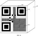
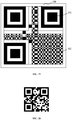
- FIG. 1A , FIG. 1B , FIG. 1C , and FIG. ID which each show a schematic structural diagram of an object on which a two-dimensional code is provided according to an embodiment of this application.
- a two-dimensional code 100 is provided on an object 10.
- the two-dimensional code 100 includes a square module array consisting of m ⁇ m modules.
- the square module array includes a location detection pattern 101 and a data information pattern 102.
- the object 10 may be a beverage bottle cap, a button, a knob, or the like.
- a form of the object 10 is not limited in this embodiment.
- a value of m is less than 21, and is not limited in this embodiment.
- the location detection pattern 101 is used for determining a location of the two-dimensional code.
- the location detection pattern 101 includes three identical location detection patterns.
- the three location detection patterns are separately distributed at an upper left corner, an upper right corner, and a lower left corner of the two-dimensional code.
- the data information pattern 102 is used for carrying data.
- the data information pattern 102 is shown by a shadow area indicated by oblique line boxes in FIG. 1A to FIG. 1D .
- Each of the modules is a first-type module or a second-type module, and a color attribute of the first-type module is different from a color attribute of the second-type module.
- the module is a minimal identification unit in a two-dimensional code. In an implementation, the module is a square.
- the first-type module is a dark-colored module, indicating a binary number 1
- the second-type module is a light-colored module, indicating a binary number 0.
- the color attribute of the first-type module is black, and the color attribute of the second-type module is white.
- the color attribute of the module is not limited in this embodiment. It should be noted that in other embodiments, the square module array may also be referred to as a square array, a matrix array, a square matrix, or a square matrix array.
- the miniature two-dimensional code includes a square module array consisting of m ⁇ m modules, where m is equal to 17, 18, 19 or 20. Even if printed in a miniature area whose side length ranges from 0.5 cm to 0.7 cm, the two-dimensional code can still be normally identified, and is suitable to be applied in a small area scenario such as an inner side of a bottle cap or a corner of an object.
- the miniature two-dimensional code may be provided at a visible location on the object by means of ink-jet printing, pasting, laser printing, electronic display, or the like.
- the manner in which the miniature two-dimensional code is provided on the object is not limited in this embodiment.
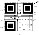
- FIG. 2 is a schematic structural diagram of a two-dimensional code according to an embodiment of this application.
- the two-dimensional code includes a square module array 200 consisting of m ⁇ m modules.
- the square module array 200 includes: a location detection pattern 201, a data information pattern 202, format information 203, and a location detection pattern separator 204.
- the location detection pattern 201 includes: a first location detection pattern 201a, a second location detection pattern 201b, and a third location detection pattern 201c.
- the square module array 200 includes 19 rows, numbered 0 to 18 from top to bottom; and includes 19 columns, numbered 0 to 18 from left to right, as shown in FIG. 2 . It should be noted that the numbers in FIG. 2 are used merely for assisting understanding, and are not included in the two-dimensional code.
- the first location detection pattern 201a occupies 7 ⁇ 7 modules in the square module array 200, whose row coordinates range from 0 to 6 and whose column coordinates range from 0 to 6.
- the second location detection pattern 201b occupies 7 ⁇ 7 modules in the square module array 200, whose row coordinates range from 0 to 6 and whose column coordinates range from 12 to 18.
- the third location detection pattern 201c occupies 7 ⁇ 7 modules in the square module array 200, whose row coordinates range from 12 to 18 and whose column coordinates range from 0 to 6.
- each location detection pattern 201 is regarded as including three overlapping concentric square arrays.
- Each module in the square module array consisting of 7 ⁇ 7 modules located at the lowest layer is a first-type module, that is, a dark-colored module.
- Each module in the square module array consisting of 5 ⁇ 5 modules located at the middle layer is a second -type module, that is, a light-colored module.
- Each module in the square module array consisting of 3 ⁇ 3 modules located at the uppermost layer is a first-type module, that is, a dark-colored module.
- each location detection pattern 201 is regarded as including a square box of 7 ⁇ 7 modules, a square box of 5 ⁇ 5 modules, and a square module array of 3 ⁇ 3 modules.
- the square boxes and the square module array are nested, adjacent and do not overlap one another.
- Each module in the square box of 7 ⁇ 7 modules is a first-type module, that is, a dark-colored module.
- Each module in the square box of 5 ⁇ 5 modules is a second -type module, that is, a light-colored module.
- Each module in the square module array of 3 ⁇ 3 modules is a first-type module, that is, a dark-colored module.
- the data information pattern 202 is used for carrying data.
- the data information pattern 202 carries 16 data blocks.
- Each data block occupies eight modules in the square module array 200, and at least one data block occupies eight adjacent modules in the square module array 200.
- a data block D1 in the figure occupies eight adjacent modules located at a lower right corner.
- the data information pattern 202 includes a first-type module and/or a second-type module. Different combinations of the first-type module and/or the second-type module indicate different data information.
- data carried in the data information pattern 202 includes: a data codeword and an error correction codeword corresponding to the data.
- the error correction codeword is used for implementing automatic error correction of the data.
- the square module array 200 further includes format information 203 indicating format information of the data during encoding.
- the format information 203 occupies thirty modules in the square module array 200, which are separately: six modules whose row coordinates are 8 and whose column coordinates range from 0 to 5, two modules whose row coordinates are 8 and whose column coordinates range from 7 to 8, six modules whose column coordinates are 8 and whose row coordinates range from 0 to 5, one module whose column coordinate is 8 and whose row coordinate is 7, eight modules whose row coordinates are 8 and whose column coordinates range from 11 to 18, and seven modules whose column coordinates are 8 and whose row coordinates range from 12 to 18, as shown by oblique line shadow areas in FIG. 2 .
- the format information 203 includes a first-type module and/or a second-type module. Different combinations of the first-type module and/or the second-type module indicate different format information.
- the format information 203 carries an error correction level corresponding to the error correction codeword.
- the error correction level includes: an error correction level L, an error correction level I, an error correction level Q, and an error correction level H.
- the error correction level L means that approximate 7% of data can be corrected.
- the error correction level I means that approximate 15% of data can be corrected.
- the error correction level Q means that approximate 25% of data can be corrected.
- the error correction level H means that approximate 30% of data can be corrected.
- the data may also be referred to as a character code.
- the error correction codeword occupies five data blocks; in the error correction level I, the error correction codeword occupies six data blocks; in the error correction level Q, the error correction codeword occupies seven data blocks; and in the error correction level H, the error correction codeword occupies eight data blocks.
- the data in the error correction level H, the data may occupy nine data blocks at most; in the error correction level Q, the data may occupy ten data blocks at most; in the error correction level I, the data may occupy twelve data blocks at most; and in the error correction level L, the data may occupy thirteen data blocks at most.
- the error correction level H is used as an example in FIG. 2 .
- the data carried by the data information pattern 202 occupies sixteen data blocks. Data occupies eight data blocks, and an error correction codeword corresponding to the data occupies eight data blocks.
- the data occupies eight first data blocks D1, D2, D3, D4, D5, D6, D7, and D8.
- the data block D1 occupies eight modules whose row coordinates range from 17 to 18 and whose column coordinates range from 15 to 18.
- the data block D2 occupies eight modules whose row coordinates range from 13 to 16 and whose column coordinates range from 17 to 18.
- the data block D3 occupies eight modules whose row coordinates range from 9 to 12 and whose column coordinates range from 17 to 18.
- the data block D4 occupies eight modules whose row coordinates range from 9 to 12 and whose column coordinates range from 15 to 16.
- the data block D5 occupies eight modules whose row coordinates range from 13 to 16 and whose column coordinates range from 15 to 16.
- the data block D6 occupies eight modules whose row coordinates range from 17 to 18 and whose column coordinates range from 11 to 14.
- the data block D7 occupies eight modules whose row coordinates range from 13 to 16 and whose column coordinates range from 13 to 14.
- the data block D8 occupies eight modules whose row coordinates range from 9 to 12 and whose column coordinates range from 13 to 14.
- the error correction codeword occupies eight second data blocks E1, E2, E3, E4, E5, E6, E7, and E8.
- the data block E1 occupies eight modules whose row coordinates range from 9 to 12 and whose column coordinates range from 11 to 12.
- the data block E2 occupies eight modules whose row coordinates range from 13 to 16 and whose column coordinates range from 11 to 12.
- the data block E3 occupies eight modules whose row coordinates range from 15 to 18 and whose column coordinates range from 9 to 10.
- the data block E4 occupies eight modules whose row coordinates range from 11 to 14 and whose column coordinates range from 9 to 10.
- the data block E5 occupies eight modules whose row coordinates range from 9 to 10 and whose column coordinates range from 7 to 10.
- the data block E6 occupies four modules whose row coordinates range from 4 to 5 and whose column coordinates range from 9 to 10 and four modules whose row coordinates range from 7 to 8 and whose column coordinates range from 9 to 10.
- the data block E7 occupies eight modules whose row coordinates range from 0 to 3 and whose column coordinates range from 9 to 10.
- the data block E8 occupies eight modules whose row coordinates range from 9 to 10 and whose column coordinates range from 2 to 5.
- the square module array 200 further includes a location detection pattern separator 204.
- the location detection pattern separator 204 is used for separating the location detection pattern 201 from the format information 203, or separating the location detection pattern 201 from the data information pattern 202.
- the location detection pattern separator 204 is usually a second-type module, that is, a light-colored module.
- the location detection pattern separator 204 occupies forty-five modules in the square module array 200, which are separately: eight modules whose row coordinates are 7 and whose column coordinates range from 0 to 7, seven modules whose row coordinates range from 0 to 6 and whose column coordinates are 7, eight modules whose row coordinates are 7 and whose column coordinates range from 11 to 18, seven modules whose row coordinates range from 0 to 6 and whose column coordinates are 11, eight modules whose row coordinates are 11 and whose column coordinates range from 0 to 7, and seven modules whose row coordinates range from 12 to 18 and whose column coordinates are 7, as shown in FIG. 2 .
- the square module array 200 further includes a positioning pattern 205.
- the positioning pattern 205 is used for preventing the two-dimensional code from rotating or being inverted.
- the positioning pattern 205 occupies six modules, which are separately: a dark-colored (black) module located in the 6 th row and the 8 th column, a light-colored (white) module located in the 6 th row and the 9 th column, a dark-colored (black) module located in the 6 th row and the 10 th column, a dark-colored (black) module located in the 8 th row and the 6 th column, a light-colored (white) module located in the 9 th row and the 6 th column, and a dark-colored (black) module located in the 10 th row and the 6 th column.
- sixteen data blocks are divided into eight first data blocks and eight second data blocks according to data codewords and error correction codewords, for example.
- the data blocks may be divided according to a data codeword and an error correction codeword corresponding to data in other manners in this embodiment.
- a two-dimensional code needs to be printed on a small area, for example, an inner side of a beverage bottle cap.
- the laser printing is preferentially used. Because a two-dimensional code includes a dark-colored (black) module and a light-colored (white) module, efficiency of the laser printing is inversely proportional to the number of light-colored modules.
- the two-dimensional code shown in FIG. 2 includes 230 light-colored modules on average. Because there are many light-colored modules, production efficiency of printing is reduced.
- the location detection pattern separator 204 includes a first location detection pattern separator 204a, a second location detection pattern separator 204b, and a third location detection pattern separator 204c.
- the first location detection pattern separator 204a occupies fifteen modules in the square module array 200, which are separately: eight modules whose row coordinates range from 0 to 7 and whose column coordinates are 7, and seven modules whose row coordinates are 7 and whose column coordinates range from 0 to 6.
- the second location detection pattern separator 204b occupies fifteen modules in the square module array 200, which are separately: eight modules whose row coordinates range from 0 to 7 and whose column coordinates are 11, and seven modules whose row coordinates are 7 and whose column coordinates range from 12 to 18.
- the third location detection pattern separator 204c occupies fifteen modules in the square module array 200, which are separately: eight modules whose row coordinates range from 11 to 18 and whose column coordinates are 7, and seven modules whose row coordinates are 11 and whose column coordinates range from 0 to 6.
- At least one of i modules occupied by the location detection pattern separator is set to be a dark-colored module.
- the number of light-colored modules is reduced, thereby improving two-dimensional code printing and production efficiency without affecting normal identification of the two-dimensional code.
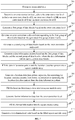
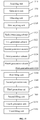
- FIG. 4 is a flowchart of a two-dimensional code identification method according to an embodiment of this application.
- the two-dimensional code identification method may be used to identify the two-dimensional code shown in FIG. 1 to FIG. 3 .
- the two-dimensional code identification method may be performed by a terminal or a server.
- the two-dimensional code identification method includes the following steps 401 to 405.
- step 401 an image including a two-dimensional code is obtained.
- step 402 a location of the two-dimensional code in the image is identified by using a location detection pattern.
- Step 403 based on the location, a square module array corresponding to the two-dimensional code is determined.
- step 404 in a case that the square module array is a square module array consisting of m ⁇ m modules, a data information pattern corresponding to the m ⁇ m modules is determined in the square module array, where m is equal to 17, 18, 19 or 20.
- step 405 the data information pattern is decoded to obtain data.
- Each of the modules is a first-type module or a second-type module, and a color attribute of the first-type module is different from a color attribute of the second-type module.
- the two-dimensional code may further include a text, an icon, and a video.
- the text, icon, and video cover a partial area (for example, a middle area) in the two-dimensional code. Visible content of the two-dimensional code is not limited in this embodiment.
- the square module array is a square module array consisting of m*m modules
- a data information pattern corresponding to the m*m modules is determined in the square module array, where m is equal to 17, 18, 19 or 20.
- FIG. 5 is a flowchart of a two-dimensional code identification method according to another embodiment of this application. This embodiment is based on the embodiment shown in FIG. 4 .
- the two-dimensional code identification method includes the following steps 501 to 515.
- step 501 an image including a two-dimensional code is obtained.
- a method of obtaining, by a terminal, an image including a two-dimensional code includes but is not limited to: placing an image including a two-dimensional code in an identification frame, selecting an image including a two-dimensional code from an album, or long pressing an image including a two-dimensional code.
- Binarization is an image processing manner, in which a pixel whose gray scale is greater than a threshold is changed into a black pixel, and a pixel whose gray scale is less than the threshold is changed into a white pixel.
- the first-type modules in the square module array are unitized as black modules
- the second-type modules are unitized as white modules.
- n candidate location detection patterns are identified from the two-dimensional code, where n ⁇ 3.
- the terminal scans the image row by row from top to bottom, or scans the image column by column from left to right.
- a black module When seven scanned adjacent modules in a same row (or a same column) are sequentially: a black module, a white module, a black module, a black module, a black module, a white module, and a black module, and a number ratio for the black module to the white module to the black module is 1:1:3:1:1, the black module whose number ratio is 3 is used to position a candidate location detection pattern.
- n candidate location detection patterns are obtained.
- a first location detection pattern, a second location detection pattern, and a third location detection pattern are determined from the n candidate location detection patterns.
- the terminal ranks the candidate location detection patterns in a descending order of matching degrees between the candidate location detection patterns and a reference location detection pattern; and determines, from top three of the location detection patterns, the first location detection pattern, the second location detection pattern, and the third location detection pattern.
- the matching degree may be a matching degree between the candidate location detection pattern and a standard location detection pattern, and is determined by the terminal during scanning.
- the terminal connects centers of any three of the candidate location detection patterns to obtain several triangles; determines a triangle having a highest similarity with an isosceles right triangle and whose longest edge is the longest; and determines, from the three candidate location detection patterns corresponding to the determined triangle, the first location detection pattern, the second location detection pattern, and the third location detection pattern.
- a location of the two-dimensional code in the image is determined by using the first location detection pattern as an upper left corner, the second location detection pattern as an upper right corner, and the third location detection pattern as a lower left corner.
- the two-dimensional code in the image may be rotated, inclined, amplified, shrunk, distorted, or inverted. Therefore, the terminal can position the two-dimensional code in the image by using the first location detection pattern, the second location detection pattern, and the third location detection pattern.
- step 505 based on the location, a square module array corresponding to the two-dimensional code is determined.
- perspective transformation is performed according to the location of the two-dimensional code in the image.
- the two-dimensional code is projected to a matrix with a fixed size, to obtain a front view of the square module array corresponding to the two-dimensional code.
- step 506 it is determined whether the square module array is a square module array consisting of m ⁇ m modules, where m is equal to 17, 18, 19 or 20.
- the square module array is a square module array consisting of m ⁇ m modules, based on a distance between the first location detection pattern and the second location detection pattern, and a width of the first location detection pattern or the second location detection pattern.
- the terminal can determine a type of the square module array based on the distance between the first location detection pattern and the second location detection pattern, and the width of the first location detection pattern or the second location detection pattern.
- the square module array is a square module array consisting of m*m modules.
- the square module array is a square module array consisting of m*m modules, based on a distance between the first location detection pattern and the third location detection pattern, and a width of the first location detection pattern or the third location detection pattern.
- the square module array is a square module array consisting of m*m modules.
- the square module array is a square module array consisting of 21*21 modules, 25*25 modules, or 29*29 modules. identification is performed according to identification modes corresponding to versions 1 to 40 of the two-dimensional code.
- step 507 in a case that the square module array is a square module array consisting of m*m modules, a data information pattern is determined based on encoding format information corresponding to the m*m modules.
- the terminal pre-stores encoding format information of a square module array consisting of m*m modules.
- the square module array is a square module array consisting of m*m modules
- a data information pattern is determined by using encoding format information corresponding to the m*m modules.
- step 508 format information in the square module array is read.
- an error correction level corresponding to an error correction codeword is obtained from the format information.
- the error correction level includes: an error correction level L, an error correction level I, an error correction level Q, and an error correction level H.
- step 510 according to the error correction level, a first group of data blocks occupied by a data codeword and a second group of data blocks occupied by an error correction codeword in the data information pattern are determined.
- step 511 the first group of data blocks are decoded to obtain the data codeword, and the second group of data blocks are decoded to obtain the error correction codeword.
- step 512 error correction is performed on the data corresponding to the data codeword by using the error correction codeword.
- error correction may be performed on the data by using the error correction codeword.
- the error correction codeword may be used to correct two types of errors: a read rejection error and a replacement error.
- the read rejection error refers to data that is not scanned or cannot be decoded in a case that a location of erroneous data is known.
- the replacement error refers to data that is incorrectly decoded in a case that a location of erroneous data is unknown. For example, when a dark-colored module changes into a light-colored module, or a light-colored module changes into a dark-colored module due to a bug, that is, when data is incorrectly decoded into another piece of data that is seemingly valid, this type of data replacement error needs to be corrected by using two error correction codewords.
- the data obtained by decoding the two-dimensional code is first data information.
- the first data information is an identifier (or an index) of the second data information.
- the second data information is information having practical meaning.
- the second data information includes at least one of: a uniform resource locator (URL), image information, audio information, text information, video information, and a lottery result.
- URL uniform resource locator
- the first data information has a first byte length
- the second data information has a second byte length
- the first byte length is less than the second byte length.
- the first byte length is 72, that is, nine characters.
- the second byte length is not limited.
- step 513 first data information is sent to a server.
- the first data information is sent to the server.
- the server stores a preset correspondence between the first data information and the second data information.
- the preset correspondence may be pre-stored.
- the first data information is information obtained by performing hash calculation on the second data information. Then, the server stores the first data information and the second data information in the preset correspondence.
- the server is provided with a first data information repository.
- the first data information repository includes unused first data information. When there is second data information, the server allocates, from the first data information repository, the first data information corresponding to the second data information.
- the preset correspondence may also be calculated in real time according to an algorithm.
- the server calculates in real time, according to a lottery algorithm, the second data information corresponding to the first data information.
- the second data information is a lottery result page corresponding to the lottery result.
- the server receives the sent first data information, searches the preset correspondence for the second data information corresponding to the first data information, and returns the second data information.
- step 514 second data information fed back by the server is received.
- the second data information is found by the server from the preset correspondence, and a first byte length of the first data information is less than a second byte length of the second data information.
- step 515 the second data information fed back is processed.
- the second data information is a URL
- a web page corresponding to the URL is jumped to.
- the second data information is image information
- content corresponding to the image information is displayed.
- the second data information is audio information
- content corresponding to the audio information is played.
- the second data information is text information
- content corresponding to the text information is displayed.
- the second data information is video information
- content corresponding to the video information is played.
- the lottery result is displayed.
- the foregoing steps may also be performed by the server, which is not limited in this embodiment.
- the square module array is a square module array consisting of m*m modules
- a data information pattern corresponding to the m*m modules is determined in the square module array, where m is equal to 17, 18, 19 or 20.
- the first data information corresponding to the second data information is further generated, and a first byte length of the first data information is less than a second byte length of the second data information.
- the two-dimensional code can still be generated.
- the two-dimensional code has a much smaller area than that of a regular two-dimensional code, but has a use range that is not significantly different from that of the regular two-dimensional code.
- a terminal connects centers of any three candidate location detection patterns to obtain several triangles; determines a triangle having a highest similarity with an isosceles right triangle and whose longest edge is the longest; and determines, from the three candidate location detection patterns corresponding to the determined triangle, a first location detection pattern, a second location detection pattern, and a third location detection pattern.
- the feature of forming an isosceles right triangle by three location detection patterns is fully utilized, to accurately determine the three location detection patterns from multiple groups of location detection patterns, thereby improving accuracy of two-dimensional code identification.
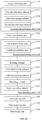
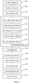
- FIG. 6 is a flowchart of a two-dimensional code generation method according to an embodiment of this application.
- the two-dimensional code generation method may be performed by a terminal or a server.
- the two-dimensional code generation method includes the following steps 601 to 604.
- step 601 to-be-encoded data is obtained.
- step 602 a data information pattern is generated based on the to-be-encoded data.
- step 603 the data information pattern and a location detection pattern are filled into a square module array consisting of m*m modules, where m is equal to 17, 18, 19 or 20.
- step 604 a two-dimensional code is generated based on the filled square module array.
- the location detection pattern is used for determining a location of the two-dimensional code
- the data information pattern is used for carrying the data.
- Each of the modules is a first-type module or a second-type module, and a color attribute of the first-type module is different from a color attribute of the second-type module.
- the two-dimensional code is generated based on the filled square module array.
- the square module array includes m*m modules, where m is equal to 17, 18, 19 or 20. Even if printed in a miniature area whose side length ranges from 0.5 cm to 0.7 cm, the two-dimensional code can still be normally identified, and is suitable to be applied in a small area scenario such as an inner side of a bottle cap or a corner of an object.
- FIG. 7 is a flowchart of a two-dimensional code generation method according to another embodiment of this application. This embodiment is based on the embodiment shown in FIG. 6 .
- the generation method includes the following steps 701 to 712.
- step 701 to-be-encoded data is obtained.
- the server determines a character type of the to-be-encoded data, and encodes the data according to a character set corresponding to the character type.
- a coded character set may include digital data, alphabetic-digital data, eight-bit byte data, or a Chinese character.
- the alphabetic- digital data includes 45 characters: numbers 0 to 9, capital letters A to Z, and nine other characters.
- an error correction level is determined.
- the error correction level includes: an error correction level L, an error correction level I, an error correction level Q, and an error correction level H.
- the server reads a default error correction level, and determines the default error correction level as an error correction level that needs to be used currently.
- the server stores a correspondence between data types and error correction levels. For example, in a case that the data type is a website, a first error correction level is used. In a case that the data type is an avatar, a second error correction level is used. The server determines a corresponding error correction level from the correspondence based on a data type of data encoded currently.
- a first group of data blocks are generated by using a data codeword based on the error correction level.
- the server after determining the error correction level, performs data encoding on the data codeword according to a character set.
- the data encoding includes converting a data codeword into a binary bit stream, and divide the generated binary bit stream into several data blocks. Each of the data blocks occupies 8 bits.
- step 704 based on the generated first group of data blocks, an error correction codeword corresponding to the first group of data blocks is generated.
- the error correction algorithm is Reed-Solomon error correction algorithm.
- step 705 a second group of data blocks are generated based on the error correction codeword.
- a data information pattern is generated based on the first group of data blocks and the second group of data blocks.
- the data information pattern carries sixteen data blocks.
- data carried by the data information pattern occupies sixteen data blocks
- the first group of data blocks includes eight data blocks
- the second group of data blocks includes eight data blocks.
- Each data block occupies eight modules in the square module array, and at least one data block occupies eight adjacent modules in the square module array.
- the square module array consisting of m*m modules, there are four remaining bits.
- the remaining bit indicates the number of modules configured to fill up the data information pattern in a final binary bit stream.
- step 707 the data information pattern and a location detection pattern are filled into the square module array.
- the server includes a blank square module array consisting of m*m modules.
- the server fills the data information pattern and the location detection pattern into corresponding locations in the blank square module array.
- a location detection pattern separator is generated.
- the location detection pattern separator is used for separating the location detection pattern from format information, or separating the location detection pattern from the data information pattern.
- the location detection pattern separator occupies i modules in the square module array, and at least one of the i modules is the first-type module, that is, a dark-colored module.
- step 709 the location detection pattern separator is filled into the square module array.
- the location detection pattern separator at least one of twenty-four modules located in the 0 th row and the 7 th column, the 0 th row and the 17 th column, the 1 st row and the 7 th column, the 1 st row and the 11 th column, the 5 th row and the 7 th column, the 5 th row and the 11 th column, the 6 th row and the 7 th column, the 6 th row and the 11 th column, the 7 th row and the 0 th column, the 7 th row and the 1 st column, the 7 th row and the 5 th column, the 7 th row and the 6 th column, the 7 th row and the 12 th column, the 7 th row and the 13 th column, the 7 th row and the 17 th column, the 7 th row and the 18 th column, the 11 th row and the 0 th column, the 1 1 th row and the 1 st column, the 1 1 th row and the 18 th column,
- step 710 the format information is generated based on the error correction level.
- step 711 the format information is filled into the square module array.
- step 707, step 709, and step 711 may be performed at the same time or in a sequential order.
- the order in which the three steps are performed is not limited in this embodiment of this application.
- the data information pattern, the location detection pattern, the location detection pattern separator, and the format information are filled into the square module array.
- step 712 a two-dimensional code is generated based on the filled square module array.
- the two-dimensional code is generated based on the filled square module array.
- the square module array includes m*m modules, where m is equal to 17, 18, 19 or 20. Even if printed in a miniature area whose side length ranges from 0.5 cm to 0.7 cm, the two-dimensional code can still be normally identified, and is suitable to be applied in a small area scenario such as an inner side of a bottle cap or a corner of an object.
- the location detection pattern separator occupies i modules in the square module array, and at least one of the i modules is the first-type module, so that the number of light-colored modules is reduced, thereby improving two-dimensional code printing and production efficiency without affecting normal identification of the two-dimensional code.
- FIG. 9 is a flowchart of a two-dimensional code generation method according to still another embodiment of this application. This embodiment is based on the embodiment shown in FIG. 7 . Before step 701, the generation method further includes steps 901 to 903.
- step 901 second data information is obtained.
- the second data information is information having practical meaning.
- the second data information includes at least one of: a URL, image information, audio information, text information, video information, and a lottery result.
- step 902 first data information corresponding to the second data information is generated, and a first byte length of the first data information is less than a second byte length of the second data information.
- the first data information is an identifier (or an index) of the second data information.
- the second data information is information having practical meaning.
- the first data information has a first byte length
- the second data information has a second byte length
- the first byte length is less than the second byte length.
- the first byte length is 72, that is, nine characters.
- the second byte length is not limited.
- the server performs hash calculation on the second data information to obtain the first data information. That is, the first data information is a hash value of the second data information.
- the second data information is "http://iteycunl.coi/topic/577820”
- the first data information obtained by hash calculation is "652384914".
- a first data information repository is provided in the server, and the first data information repository includes unused first data information.
- the server allocates, from the first data information repository, first data information corresponding to the second data information.
- the first data information is an information identifier
- the second data information is a URL.
- An information identifier library (first data information repository) is provided in the server.
- the information identifier library includes 1000 unused information identifiers.
- the server allocates, from the information identifier library, an information identifier corresponding to the URL.
- a preset correspondence is obtained based on the first data information and the second data information.
- the preset correspondence includes a correspondence between the first data information and the second data information.
- the server stores the first data information and the second data information in the preset correspondence.
- the server may determine the first data information as the to-be-encoded data, and the method proceeds to step 701.
- a two-dimensional code is generated based on the filled square module array.
- the square module array includes m*m modules, where m is equal to 17, 18, 19 or 20. Even if printed in a miniature area whose side length ranges from 0.5 cm to 0.7 cm, the two-dimensional code can still be normally identified, and is suitable to applied in a small area scenario such as an inner side of a bottle cap or a corner of an object.
- the location detection pattern separator occupies i modules in the square module array, and at least one of the i modules is the first-type module, so that the number of light-colored modules is reduced, thereby improving two-dimensional code printing and production efficiency without affecting normal identification of the two-dimensional code.
- first data information corresponding to second data information is further generated, and a first byte length of the first data information is less than a second byte length of the second data information. Even if the second byte length of the second data information is long, the two-dimensional code can still be generated.
- the two-dimensional code has a much smaller area than that of a regular two-dimensional code, but has a use range that is not significantly different from that of the regular two-dimensional code.
- step 901, step 902, and step 903 may be replaced by step 1001 and step 1002, as shown in FIG. 10 .
- step 1001 second data information is sent to a server.
- the second data information is information having practical meaning.
- the second data information includes at least one of: a URL, image information, audio information, text information, video information, and a lottery result.
- step 1002 first data information fed back by the server is received, and a first byte length of the first data information is less than a second byte length of the second data information.
- the first data information may be an identifier (or an index) of the second data information.
- the second data information is information having practical meaning.
- the first data information has a first byte length
- the second data information has a second byte length
- the first byte length is less than the second byte length.
- the first byte length is 72, that is, nine characters.
- the second byte length is not limited.
- the server performs hash calculation on the second data information to obtain the first data information. That is, the first data information is a hash value of the second data information.
- first data information obtained by hash calculation is "652384914".
- a first data information repository is provided in the server, and the first data information repository includes unused first data information.
- the server allocates, from the first data information repository, first data information corresponding to the second data information.
- the first data information is an information identifier
- the second data information is a URL.
- An information identifier library (first data information repository) is provided in the server.
- the information identifier library includes 1000 unused information identifiers.
- the server allocates, from the information identifier library, an information identifier corresponding to the URL.
- the terminal may determine the first data information as the to-be-encoded data, and the method proceeds to step 701.
- the two-dimensional code is generated based on the filled square module array.
- the square module array includes m*m modules, where m is equal to 17, 18, 19 or 20. Even if printed in a miniature area whose side length ranges from 0.5 cm to 0.7 cm, the two-dimensional code can still be normally identified, and is suitable to be applied in a small area scenario such as an inner side of a bottle cap or a corner of an object.
- the location detection pattern separator occupies i modules in the square module array, and at least one of the i modules is the first-type module, so that the number of light-colored modules is reduced, thereby improving two-dimensional code printing and production efficiency without affecting normal identification of the two-dimensional code.
- first data information fed back by a server is received, where a first byte length of the first data information is less than a second byte length of second data information. In this way, a byte length of to-be-encoded data is reduced without affecting normal identification of the two-dimensional code.
- FIG. 11 is a schematic structural diagram of a two-dimensional code identification device according to an embodiment of this application.
- the device includes: an image obtaining unit 1110, a location identification unit 1120, a first determining unit 1130, a second determining unit 1140 and a data decoding unit 1150.
- the image obtaining unit 1110 is configured to obtain an image including a two-dimensional code.
- the location identification unit 1120 is configured to identify a location of the two-dimensional code in the image by using a location detection pattern.
- the first determining unit 1130 is configured to determine, based on the location, a square module array corresponding to the two-dimensional code.
- the second determining unit 1140 is configured to determine, in a case that the square module array is a square module array consisting of m*m modules, a data information pattern corresponding to the m*m modules in the square module array, where m is equal to 17, 18, 19 or 20.
- the data decoding unit 1150 is configured to decode the data information pattern to obtain data.
- Each of the modules is a first-type module or a second-type module, and a color attribute of the first-type module is different from a color attribute of the second-type module.
- the square module array is a square module array consisting of m*m modules
- a data information pattern corresponding to the m*m modules is determined in the square module array, where m is equal to 17, 18, 19 or 20.
- FIG. 12 is a schematic structural diagram of a two-dimensional code identification device according to another embodiment of this application. This embodiment is based on the embodiment shown in FIG. 11 .
- the location identification unit 1120 includes: a first identification subunit 1122, a first determining subunit 1124, and a second determining subunit 1126.
- the first identification subunit 1122 is configured to identify n candidate location detection patterns from the two-dimensional code, where n ⁇ 3.
- the first determining subunit 1124 is configured to determine, from the n candidate location detection patterns, a first location detection pattern, a second location detection pattern, and a third location detection pattern.
- the second determining subunit 1126 is configured to determine a location of the two-dimensional code in the image by using the first location detection pattern as an upper left corner, the second location detection pattern as an upper right corner, and the third location detection pattern as a lower left corner.
- the first determining subunit 1124 is configured to: rank the candidate location detection patterns in a descending order of matching degrees between the candidate location detection patterns and a reference location detection pattern; and determine, from top three of the location detection patterns, the first location detection pattern, the second location detection pattern, and the third location detection pattern; or the first determining subunit 1124 is configured to: connect centers of any three of the candidate location detection patterns to obtain triangles; determine, from the obtained triangles, a triangle having a highest similarity with an isosceles right triangle and whose longest edge is the longest; and determine, from the three candidate location detection patterns corresponding to the determined triangle, the first location detection pattern, the second location detection pattern, and the third location detection pattern.
- the second determining unit 1140 includes: a third determining subunit 1142 and a fourth determining subunit 1144.
- the third determining subunit 1142 is configured to determine whether the square module array is a square module array consisting of m*m modules, based on a distance between the first location detection pattern and the second location detection pattern, and a width of the first location detection pattern or the second location detection pattern.
- the fourth determining subunit 1144 is configured to determine, in a case that the square module array is a square module array consisting of m*m modules, a data information pattern according to encoding format information corresponding to the m*m modules.
- the data decoding unit 1150 includes: a reading subunit 1151, an obtaining subunit 1152, a fifth determining subunit 1153, a decoding subunit 1154, and an error correction subunit 1155.
- the reading subunit 1151 is configured to read format information in the square module array.
- the obtaining subunit 1152 is configured to obtain from the format information, an error correction level corresponding to an error correction codeword.
- the error correction level includes: an error correction level L, an error correction level I, an error correction level Q, and an error correction level H.
- the fifth determining subunit 1153 is configured to determine, based on the error correction level, a first group of data blocks occupied by a data codeword and a second of data blocks occupied by an error correction codeword in the data information pattern.
- the decoding subunit 1154 is configured to: decode the first group of data blocks to obtain the data codeword, and decode the second group of data blocks to obtain the error correction codeword.
- the error correction subunit 1155 is configured to perform error correction on the data by using the error correction codeword.
- the square module array further includes: a location detection pattern separator for separating the location detection pattern from format information, or separating the location detection pattern from the data information pattern.
- the location detection pattern separator occupies i modules in the square module array, and at least one of the i modules is the first-type module.
- the format information indicates format information of the data during encoding.
- the device further includes: a first sending unit 1160 and a first receiving unit 1170.
- the first sending unit 1160 is configured to send the first data information to a server.
- the first receiving unit 1170 is configured to receive second data information fed back by the server.
- the second data information is found by the server from a preset correspondence, and a first byte length of the first data information is less than a second byte length of the second data information.
- the second data information includes at least one of: a uniform resource locator URL, image information, audio information, text information, video information, and a lottery result.
- the first data information is obtained by performing hash calculation on the second data information.
- the first data information is from a first data information repository and allocated for the second data information.
- the first data information repository includes unused first data information.
- the device further includes a processing unit 1180, configured to perform one of the following operations: displaying, in a case that the second data information is image information, content corresponding to the image information; playing, in a case that the second data information is audio information, content corresponding to the audio information; or displaying, in a case that the second data information is text information, content corresponding to the text information; playing, in a case that the second data information is video information, content corresponding to the video information; and displaying, in a case that the second data information is a lottery result, the lottery result.
- a processing unit 1180 configured to perform one of the following operations: displaying, in a case that the second data information is image information, content corresponding to the image information; playing, in a case that the second data information is audio information, content corresponding to the audio information; or displaying, in a case that the second data information is text information, content corresponding to the text information; playing, in a case that the second data information is video information, content corresponding to the video information; and displaying,
- the square module array is a square module array consisting of m*m modules
- a data information pattern corresponding to the m*m modules is determined in the square module array, where m is equal to 17, 18, 19 or 20.
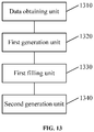
- FIG. 13 is a schematic structural diagram of a two-dimensional code generation device according to an embodiment of this application.
- the device includes: a data obtaining unit 1310, a first generation unit 1320, a first filling unit 1330 and a second generation unit 1340.
- the data obtaining unit 1310 is configured to obtain to-be-encoded data.
- the first generation unit 1320 is configured to generate a data information pattern based on the to-be-encoded data.
- the first filling unit 1330 is configured to fill the data information pattern and a location detection pattern into a square module array consisting of m*m modules, where m is equal to 17, 18, 19 or 20.
- the second generation unit 1340 is configured to generate a two-dimensional code based on the filled square module array.
- the location detection pattern is used for determining a location of the two-dimensional code
- the data information pattern is used for carrying the data.
- Each of the modules is a first-type module or a second-type module, and a color attribute of the first-type module is different from a color attribute of the second-type module.
- the two-dimensional code is generated based on the filled square module array.
- the square module array includes m*m modules. Even if printed in a miniature area whose side length ranges from 0.5 cm to 0.7 cm, the two-dimensional code can still be normally identified, and is suitable to be applied in a small area scenario such as an inner side of a bottle cap or a corner of an object.
- FIG. 14 is a schematic structural diagram of a two-dimensional code generation device according to another embodiment of this application. This embodiment is based on the embodiment shown in FIG. 13 .
- the first generation unit 1320 includes:a sixth determining subunit 1321, a first generation subunit 1322, a second generation subunit 1323, a third generation subunit 1324, and a fourth generation subunit 1325.
- the sixth determining subunit 1321 is configured to determine an error correction level.
- the error correction level includes: an error correction level L, an error correction level I, an error correction level Q, and an error correction level H.
- the first generation subunit 1322 is configured to generate a first group of data blocks by using the data according to the error correction level.
- the second generation subunit 1323 is configured to generate, based on the generated first group of data blocks, an error correction codeword corresponding to the first group of data blocks.
- the third generation subunit 1324 is configured to generate a second group of data blocks according to the error correction codeword.
- the fourth generation subunit 1325 is configured to generate a data information pattern based on the first group of data blocks and the second group of data blocks.
- the data information pattern carries sixteen data blocks.
- the generation device further includes: a third generation unit 1350 and a second filling unit 1360.
- the third generation unit 1350 is configured to generate format information based on the error correction level.
- the second filling unit 1360 is configured to fill the format information into the square module array.
- the generation device further includes: a fourth generation unit 1370 and a third filling unit 1380.
- the fourth generation unit 1370 is configured to generate a location detection pattern separator.
- the location detection pattern separator is used for separating the location detection pattern from the format information, or separating the location detection pattern from the data information pattern.
- the third filling unit 1380 is configured to fill the location detection pattern separator into the square module array.
- the location detection pattern separator occupies i modules in the square module array, and at least one of the i modules is the first-type module.
- the format information indicates format information of the data during encoding.
- the two-dimensional code is generated based on the filled square module array.
- the square module array includes m*m modules, where m is equal to 17, 18, 19 or 20. Even if printed in a miniature area whose side length ranges from 0.5 cm to 0.7 cm, the two-dimensional code can still be normally identified, and is suitable to be applied in a small area scenario such as an inner side of a bottle cap or a corner of an object.
- the location detection pattern separator occupies i modules in the square module array, and at least one of the i modules is the first-type module, so that the number of light-colored modules is reduced, thereby improving two-dimensional code printing and production efficiency without affecting normal identification of the two-dimensional code.
- a terminal further connects centers of any three candidate location detection patterns to obtain triangles; determines a triangle having a highest similarity with an isosceles right triangle and whose longest side is the longest; and determines, from the three candidate location detection patterns corresponding to the determined triangle, a first location detection pattern, a second location detection pattern, and a third location detection pattern.
- the feature of forming an isosceles right triangle by three location detection patterns is fully utilized, to accurately determine the three location detection patterns from multiple groups of location detection patterns, thereby improving accuracy of two-dimensional code identification.
- FIG. 15 is a schematic structural diagram of a two-dimensional code generation device according to still another embodiment of this application. This embodiment is based on the embodiment shown in FIG. 13 .
- the generation device further includes: an acquiring unit 1510, a generation unit 1520, and an obtaining unit 1530.
- the acquiring unit 1510 is configured to acquire second data information.
- the generation unit 1520 is configured to generate first data information corresponding to the second data information, and a first byte length of the first data information is less than a second byte length of the second data information.
- the obtaining unit 1530 is configured to obtain a preset correspondence based on the first data information and the second data information.
- the preset correspondence includes a correspondence between the first data information and the second data information.
- the data is first data information.
- the second data information includes at least one of: a uniform resource locator URL, image information, audio information, text information, video information, and a lottery result.
- a two-dimensional code is generated based on the filled square module array.
- the square module array includes m*m modules, where m is equal to 17, 18, 19 or 20. Even if printed in a miniature area whose side length ranges from 0.5 cm to 0.7 cm, the two-dimensional code can still be normally identified, and is suitable to be applied in a small area scenario such as an inner side of a bottle cap or a corner of an object.
- the location detection pattern separator occupies i modules in the square module array, and at least one of the i modules is the first-type module, so that the number of light-colored modules is reduced, thereby improving two-dimensional code printing and production efficiency without affecting normal identification of the two-dimensional code.
- first data information corresponding to second data information is further generated, and a first byte length of the first data information is less than a second byte length of the second data information.
- the two-dimensional code can still be generated.
- the two-dimensional code has a much smaller area than that of a regular two-dimensional code, but has a use range that is not significantly different from that of the regular two-dimensional code.
- FIG. 16 is a schematic structural diagram of a two-dimensional code generation device according to yet another embodiment of this application. This embodiment is based on the embodiment shown in FIG. 13 .
- the generation device further includes: a second sending unit 1610 and a second receiving unit 1620.
- the second sending unit 1610 is configured to send the second data information to a server.
- the second receiving unit 1620 is configured to receive the first data information fed back by the server.
- a first byte length of the first data information is less than a second byte length of the second data information.
- the data is first data information.
- the second data information includes at least one of: a uniform resource locator URL, image information, audio information, text information, video information, and a lottery result.
- the first data information is obtained by performing hash calculation on the second data information.
- the first data information is from a first data information repository and allocated for the second data information.
- the first data information repository includes unused first data information.
- the two-dimensional code is generated based on the filled square module array.
- the square module array includes m*m modules, where m is equal to 17, 18, 19 or 20. Even if printed in a miniature area whose side length ranges from 0.5 cm to 0.7 cm, the two-dimensional code can still be normally identified, and is suitable to be applied in a small area scenario such as an inner side of a bottle cap or a corner of an object.
- the location detection pattern separator occupies i modules in the square module array, and at least one of the i modules is the first-type module, so that the number of light-colored modules is reduced, thereby improving two-dimensional code printing and production efficiency without affecting normal identification of the two-dimensional code.
- first data information corresponding to second data information is further generated, and a first byte length of the first data information is less than a second byte length of the second data information.
- the two-dimensional code has a much smaller area than that of a regular two-dimensional code, but has a use range that is not significantly different from that of the regular two-dimensional code.
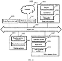
- FIG. 17 is a block diagram of a terminal 1700 according to an embodiment of this application.
- the terminal may include components such as a radio frequency (RF) circuit 1701, a memory 1702 that includes one or more computer-readable storage media, an input unit 1703, a display unit 1704, a sensor 1705, an audio circuit 1706, a Wireless Fidelity (Wi-Fi) module 1707, a processor 1708 that includes one or more processing cores, and a power supply 1709.
- RF radio frequency
- the RF circuit 1701 may be configured to receive and send signals during information receiving and sending or during a call. Particularly, the RF circuit 1701 receives downlink information from a base station, then delivers the downlink information to one or more processors 1708 for processing, and sends related uplink data to the base station.
- the RF circuit 1701 includes but is not limited to an antenna, at least one amplifier, a tuner, one or more oscillators, a subscriber identity module (SIM) card, a transceiver, a coupler, a low noise amplifier (LNA), a duplexer, and the like.
- SIM subscriber identity module
- LNA low noise amplifier
- the RF circuit 1701 may also communicate with a network and another device by means of wireless communication.
- the wireless communication may use any communications standard or protocol, which includes but is not limited to, Global System for Mobile Communications (GSM), general packet radio service (GPRS), Code Division Multiple Access (CDMA), Wideband Code Division Multiple Access (WCDMA), Long Term Evolution (LTE), email, short message service (SMS), and the like.
- GSM Global System for Mobile Communications
- GPRS general packet radio service
- CDMA Code Division Multiple Access
- WCDMA Wideband Code Division Multiple Access
- LTE Long Term Evolution
- email short message service
- SMS short message service
- the memory 1702 may be configured to store a software program and module.
- the processor 1708 runs the software program and module stored in the memory 1702, to implement various functional applications and data processing.
- the memory 1702 may mainly include a program storage area and a data storage area.
- the program storage area may store an operating system, an application program required by at least one function (such as a sound playing function and an image playing function), and the like.
- the data storage area may store data (such as audio data and a telephone book) generated according to use of the terminal, and the like.
- the memory 1702 may include a high speed random access memory, and may further include a non-volatile memory, such as at least one magnetic disk storage device, a flash memory, or other volatile solid-state storage devices.
- the memory 1702 may further include a memory controller, to provide access to the memory 1702 by the processor 1708 and the input unit 1703.
- the input unit 1703 may be configured to receive input digit or character information, and generate a keyboard, mouse, joystick, optical or track ball signal input related to the user setting and function control.
- the input unit 1703 may include a touch-sensitive surface and another input device.
- the touch-sensitive surface which may also be referred to as a touch screen or a touch panel, may collect a touch operation of a user on or near the touch-sensitive surface (such as an operation of a user on or near the touch-sensitive surface by using any suitable object or accessory such as a finger or a stylus), and drive a corresponding connection apparatus according to a preset program.
- the touch-sensitive surface may include two parts: a touch detection device and a touch controller.
- the touch detection device detects a touch location of the user, detects a signal generated by the touch operation, and transfers the signal to the touch controller.
- the touch controller receives touch information from the touch detection device, converts the touch information into touch point coordinates, and then sends the touch point coordinates to the processor 1708.
- the touch controller can receive and execute a command sent from the processor 1708.
- the touch-sensitive surface may be implemented in multiple types, such as a resistive type, a capacitive type, an infrared type, and a surface acoustic wave type.
- the input unit 1703 may further include another input device.
- the another input device may include but is not limited to one or more of a physical keyboard, a function key (for example, a volume control key or a power on/off key), a trackball, a mouse, or a joystick.
- the display unit 1704 may be configured to display information input by the user or information provided for the user and various graphic user interfaces of the terminal, where the graphic user interfaces may include a figure, a text, an icon, a video, and any combination thereof.
- the display unit 1704 may include a display panel.
- the display panel may be configured in a form of a liquid crystal display (LCD), an organic light-emitting diode (OLED), or the like.
- the touch-sensitive surface may cover the display panel. After detecting a touch operation on or near the touch-sensitive surface, the touch-sensitive surface transfers the touch operation to the processor 1708 to determine a type of a touch event, and then the processor 1708 provides corresponding visual output on the display panel according to the type of the touch event.
- the touch-sensitive surface and the display panel function as two separate parts to implement input and output functions, in some embodiments, the touch-sensitive surface and the display panel may be integrated to implement the input and output functions.
- the terminal may further include at least one sensor 1705 such as an optical sensor, a motion sensor, and other sensors.
- the optical sensor may include an ambient light sensor and a proximity sensor.
- the ambient light sensor may adjust luminance of the display panel according to brightness of the ambient light.
- the proximity sensor may switch off the display panel and/or backlight when the terminal is moved close to an ear.
- a gravity acceleration sensor may detect a value of acceleration in all directions (which generally indicates three axis), may detect a value and a direction of the gravity when being static, and may be configured to identify an application of a mobile phone gesture (such as switching between horizontal and longitudinal screens, a related game, and gesture calibration of a magnetometer), a related function of vibration identification (such as a pedometer and a knock), and the like.
- a mobile phone gesture such as switching between horizontal and longitudinal screens, a related game, and gesture calibration of a magnetometer
- a related function of vibration identification such as a pedometer and a knock
- Another sensor such as a gyroscope, a barometer, a hygrometer, a thermometer, and an infrared sensor, may be provided in the terminal, which is not described herein again.
- the audio circuit 1706, a speaker, and a microphone may provide audio interfaces between the user and the terminal.
- the audio circuit 1706 may convert received audio data into an electrical signal and transmit the electrical signal to the speaker.
- the speaker converts the electrical signal into a sound signal for output.
- the microphone converts a collected sound signal into an electrical signal.
- the audio circuit 1706 receives the electrical signal and converts the electrical signal into audio data, and outputs the audio data to the processor 1708 for processing. Then, the processor 1708 sends the audio data to, for example, another terminal via the RF circuit 1701, or outputs the audio data to the memory 1702 for further processing.
- the audio circuit 1706 may further include an earplug jack, to provide communication between a peripheral earphone and the terminal.
- Wi-Fi belongs to a short distance wireless transmission technology.
- the terminal may help, via the Wi-Fi module 1707, a user to receive and send an email, browse a web page, and access stream media, and the like, which provides wireless broadband Internet access for the user.
- FIG. 17 shows the Wi-Fi module 1707, it may be understood that the wireless communications unit is not a necessary component of the terminal, and when required, the the Wi-Fi module may be omitted as long as the scope of the essence of the present disclosure is not changed.
- the processor 1708 is a control center of the terminal, which is connected to various parts of the mobile phone by using various interfaces and lines.
- the processor 1708 runs or executes a software program and/or module stored in the memory 1702 and calls data stored in the memory 1702, to perform various functions of the terminal and data processing, so as to perform overall monitoring on the mobile phone.
- the processor 1708 may include one or more processing cores.
- the processor 1708 may integrate an application processor and a modem processor.
- the application processor mainly processes an operating system, a user interface, an application program, and the like.
- the modem processor mainly processes wireless communication. It may be understood that the foregoing modem processor may not be integrated into the processor 1708.
- the terminal further includes the power supply 1709 (such as a battery) for supplying power to the components.
- the power supply may be logically connected to the processor 1708 by using a power management system, thereby implementing functions such as charging, discharging, and power consumption management by using the power management system.
- the power supply 1709 may further include one or more of a direct current or alternating current power supply, a re-charging system, a power failure detection circuit, a power supply converter or inverter, a power supply state indicator, and any other components.
- the terminal may further include a camera, a Bluetooth module, and the like, which are not described herein.
- the processor 1708 in the terminal runs one or more program instructions stored in the memory 1702, to implement the identification and generation methods provided in the foregoing method embodiments.
- the program may be stored in a computer-readable storage medium.
- the storage medium may include: a read-only memory (ROM), a random access memory (RAM), a magnetic disk, an optical disc, or the like.
- a server 1800 includes a central processing unit (CPU) 1801, a system memory 1804 including a RAM 1802 and a ROM 1803, and a system bus 1805 connecting the system memory 1804 and the CPU 1801.
- the server 1800 further includes a basic input/output system (I/O system) 1806 configured to transmit information between components in a computer, and a mass storage device 1807 configured to store an operating system 1813, an application program 1818, and another program module 1818.
- I/O system basic input/output system
- the basic I/O system 1806 includes a display 1808 configured to display information, and an input device 1809 configured to input information by a user, such as a mouse and a keyboard.
- the display 1808 and the input device 1809 are both connected to the CPU 1801 by using an input/output controller 1810 connected to the system bus 1805.
- the basic I/O system 1806 may further include the input/output controller 1810, so as to receive and process input from multiple other devices, such as the keyboard, the mouse, or an electronic stylus.
- the input/output controller 1810 further provides an output to a display screen, a printer or another type of output device.
- the mass storage device 1807 is connected to the CPU 1801 by using a mass storage controller (not shown) connected to the system bus 1805.
- the mass storage device 1807 and an associated computer-readable medium provide non-volatile storage for the server 1800. That is, the mass storage device 1807 may include a computer-readable medium (not shown) such as a hard disk or a CD-ROM.
- the computer-readable medium may include a computer storage medium and a communications medium.
- the computer storage medium includes volatile and non-volatile media, and removable and non-removable media implemented by using any method or technology and used for storing information such as a computer-readable instruction, a data structure, a program module, or other data.
- the computer storage medium includes a RAM, a ROM, an EPROM, an EEPROM, a flash memory or other solid storage devices; a CD-ROM, a DVD or other optical storages; and a cassette, a magnetic tape, a disk storage or other magnetic storage devices.
- the system memory 1804 and the mass storage device 1807 may be collectively referred to as a memory.
- the server 1800 may further be connected to a remote computer on a network over a network such as the Internet. That is, the server 1800 may be connected to a network 1812 by using a network interface unit 1811 connected to the system bus 1805, or may be connected to another type of network or a remote computer system (not shown) by using a network interface unit 1811.
- the CPU 1801 in the server runs one or more program instructions stored in the memory 1804, to implement the identification and generation methods provided in the foregoing method embodiments.
- the memory further includes one or more programs, where the one or more programs are stored in the memory, and the one or more programs include instructions for performing the identification and generation methods provided in the embodiments of the present disclosure.
- a non-volatile storage medium which stores one or more computer programs.
- the computer program includes processor-executable instructions. The instructions, when being executed by a computer, cause the computer to perform the identification and generation methods provided in the method embodiments.
- the non-volatile storage medium may be located in the terminal or the server described above.
- FIG. 19 is a schematic structural diagram of a two-dimensional code according to an embodiment of this application.
- the two-dimensional code 100 includes a square module array consisting of m*m modules.
- the square module array includes a location detection pattern 101 and a data information pattern 102.
- the location detection pattern 101 is used for determining a location of the two-dimensional code.
- the location detection pattern 101 may include three identical location detection patterns.
- the three location detection patterns are separately distributed on an upper left corner, an upper right corner, and a lower left corner of the two-dimensional code.
- the data information pattern 102 is used for carrying data.
- the data information pattern 102 is shown by a shadow area indicated by an oblique line box in FIG. 1 .
- Each of the modules is a first-type module or a second-type module, and a color attribute of the first-type module is different from a color attribute of the second-type module.
- the module is a minimal identification unit in a two-dimensional code. In an implementation, the module is a square.
- the first-type module is a dark-colored module, indicating a binary number 1
- the second-type module is a light-colored module, indicating a binary number 0.
- the color attribute of the first-type module is black, and the color attribute of the second-type module is white.
- the color attribute of the module is not limited in this embodiment. It should be noted that in different embodiments, the square module array may also be referred to as a square array, a matrix array, a square matrix, or a square matrix array.
- FIG. 20 shows a two-dimensional code pattern generated by using a square module array according to an embodiment of this application.
- the miniature two-dimensional code includes a square module array consisting of m*m modules. Even if printed in a miniature area whose side length ranges from 0.5 cm to 0.7 cm, the two-dimensional code can still be normally identified, and is suitable to be applied in a small area scenario such as an inner side of a bottle cap or a corner of an object.
- the miniature two-dimensional code may be provided by means of ink-jet printing, pasting, laser printing, electronic display, or the like.
- the manner of providing the two-dimensional code is not limited in this embodiment.
- the program may be stored in a computer-readable storage medium.
- the storage medium may be a read-only memory, a magnetic disk, an optical disc, or the like.
Landscapes
- Engineering & Computer Science (AREA)
- Physics & Mathematics (AREA)
- General Physics & Mathematics (AREA)
- Theoretical Computer Science (AREA)
- Health & Medical Sciences (AREA)
- General Health & Medical Sciences (AREA)
- Toxicology (AREA)
- Artificial Intelligence (AREA)
- Computer Vision & Pattern Recognition (AREA)
- Electromagnetism (AREA)
- Quality & Reliability (AREA)
- Editing Of Facsimile Originals (AREA)
- Image Processing (AREA)
- Image Analysis (AREA)
- Character Input (AREA)
Abstract
Description
- This application claims priority to Chinese Patent Application No.
201610688875.4 - This application relates to the technical field of information processing, and in particular to an object on which a two-dimensional code is provided, a two-dimensional code generation method, a two-dimensional code identification method, a two-dimensional code generation device, a two-dimensional code identification device, and a storage medium.
- With continuous development of information processing technologies, two-dimensional codes are widely used due to features of wide encoding ranges, strong fault tolerance capability and use convenience. A quick response (QR) two-dimensional code is one type of two-dimensional code. The QR two-dimensional code includes a square module array consisting of square modules arranged in n rows by n columns. Each of the modules is a minimal identification unit.
- Currently, there are 40 versions of two-dimensional codes, which are separately
version 1 to version 40. A dimension of theversion 1 is 21∗21 modules, and each later version includes four more modules than a previous version in both a row direction and a column direction, until the version 40. The dimension of the version 40 is 177∗177 modules. - In some scenarios, a two-dimensional code needs to be printed on a small area, for example, an inner side of a beverage bottle cap. Even if a two-dimensional code of the
version 1 is printed on an inner side of the beverage bottle cap, the two-dimensional code cannot be normally identified because the printed pattern is small. - According to embodiments of this application, an object on which a two-dimensional code is provided, a two-dimensional code generation method, a two-dimensional code identification method, a two-dimensional code generation device, a two-dimensional code identification device, and a storage medium are provided.
- According to a first aspect, an object on which a two-dimensional code is provided is provided. The two-dimensional code includes a square module array consisting of m∗m modules, and the square module array includes a location detection pattern and a data information pattern. The location detection pattern is used for determining a location of the two-dimensional code. The data information pattern is used for carrying data. Each of the modules is a first-type module or a second-type module, a color attribute of the first-type module is different from a color attribute of the second-type module, and m is equal to 17, 18, 19 or 20.
- According to a second aspect, a two-dimensional code identification method is provided. The method includes: obtaining an image including a two-dimensional code; identifying a location of the two-dimensional code in the image by using a location detection pattern; determining, based on the location, a square module array corresponding to the two-dimensional code; determining, in a case that the square module array is a square module array consisting of m∗m modules, a data information pattern corresponding to the m∗m modules in the square module array; and decoding the data information pattern to obtain a data codeword. Each of the modules is a first-type module or a second-type module, a color attribute of the first-type module is different from a color attribute of the second-type module, and m is equal to 17, 18, 19 or 20.
- According to a third aspect, a two-dimensional code generation method is provided. The method includes: obtaining to-be-encoded data; generating a data information pattern based on the to-be-encoded data; filling the data information pattern and a location detection pattern into a square module array consisting of m∗m modules; and generating a two-dimensional code based on the filled square module array. The location detection pattern is used for determining a location of the two-dimensional code, the data information pattern is used for carrying the data, each of the modules is a first-type module or a second-type module, a color attribute of the first-type module is different from a color attribute of the second-type module, and m is equal to 17, 18, 19 or 20.
- According to a fourth aspect, a two-dimensional code identification device is provided. The device includes: an image obtaining unit, a location identification unit, a first determining unit, a second determining unit and a data decoding unit. The image obtaining unit is configured to obtain an image including a two-dimensional code. The location identification unit is configured to identify a location of the two-dimensional code in the image by using a location detection pattern. The first determining unit is configured to determine, based on the location, a square module array corresponding to the two-dimensional code. The second determining unit is configured to determine, in a case that the square module array is a square module array consisting of m∗m modules, a data information pattern corresponding to the m∗m modules in the square module array. The data decoding unit is configured to decode the data information pattern to obtain data. Each of the modules is a first-type module or a second-type module, a color attribute of the first-type module is different from a color attribute of the second-type module, and m is equal to 17, 18, 19 or 20.
- According to a fifth aspect, a two-dimensional code generation device is provided. The device includes: a data obtaining unit, a first generation unit, a first filling unit and a second generation unit. The data obtaining unit is configured to obtain to-be-encoded data. The first generation unit is configured to generate a data information pattern based on the to-be-encoded data. The first filling unit is configured to fill the data information pattern and a location detection pattern into a square module array consisting of m∗m modules. The second generation unit is configured to generate a two-dimensional code based on the filled square module array. The location detection pattern is used for determining a location of the two-dimensional code, the data information pattern is used for carrying the data, each of the modules is a first-type module or a second-type module, a color attribute of the first-type module is different from a color attribute of the second-type module, and m is equal to 17, 18, 19 or 20.
- According to a sixth aspect, a two-dimensional code is provided. The two-dimensional code includes a square module array consisting of m∗m modules, and the square module array includes a location detection pattern and a data information pattern. The location detection pattern is used for determining a location of the two-dimensional code. The data information pattern is used for carrying data. Each of the modules is a first-type module or a second-type module, a color attribute of the first-type module is different from a color attribute of the second-type module, and m is equal to 17, 18, 19 or 20.
- According to a seventh aspect, a non-volatile storage medium is provided, which stores one or more computer programs. The computer programs includes processor-executable instructions, and the instructions, when being executed by a computer, cause the computer to perform the following operations: obtaining an image including a two-dimensional code; identifying a location of the two-dimensional code in the image by using a location detection pattern; determining, based on the location, a square module array corresponding to the two-dimensional code; determining, in a case that the square module array is a square module array consisting of m∗m modules, a data information pattern corresponding to the m∗m modules in the square module array; and decoding the data information pattern to obtain data. Each of the modules is a first-type module or a second-type module, a color attribute of the first-type module is different from a color attribute of the second-type module, and m is equal to 17, 18, 19 or 20.
- According to an eighth aspect, a non-volatile storage medium is provided, which stores one or more computer programs. The computer programs include processor-executable instructions, and the instructions, when being executed by a computer, cause the computer to perform the following operations: obtaining to-be-encoded data; generating a data information pattern based on the to-be-encoded data; filling the data information pattern and a location detection pattern into a square module array consisting of m∗m modules; and generating a two-dimensional code based on the filled square module array. The location detection pattern is used for determining a location of the two-dimensional code, the data information pattern is used for carrying the data, each of the modules is a first-type module or a second-type module, a color attribute of the first-type module is different from a color attribute of the second-type module, and m is equal to 17, 18, 19, or 20.
- According to the embodiments of this application, a miniature two-dimensional code is provided. The two-dimensional code includes a square module array consisting of m∗m modules, where m is equal to 17, 18, 19 or 20. Even if printed in a miniature area whose side length ranges from 0.5 cm to 0.7 cm, the two-dimensional code can still be normally identified, and is suitable to be applied in a small area scenario such as an inner side of a bottle cap or a corner of an object.
- To describe the technical solutions in the embodiments of this application more clearly, the accompanying drawings required for describing the embodiments are described simply hereinafter. Apparently, the accompanying drawings in the following description show merely some embodiments of this application, and a person of ordinary skill in the art may obtain other drawings from these accompanying drawings without creative efforts.
-
FIG. 1A is a schematic structural diagram of an object on which a two-dimensional code is provided according to an embodiment of this application; -
FIG. 1B is a schematic structural diagram of an object on which a two-dimensional code is provided according to another embodiment of this application; -
FIG. 1C is a schematic structural diagram of an object on which a two-dimensional code is provided according to still another embodiment of this application; - FIG. ID is a schematic structural diagram of an object on which a two-dimensional code is provided according to yet another embodiment of this application;
-
FIG. 2 is a schematic structural diagram of a two-dimensional code according to an embodiment of this application; -
FIG. 3 is a schematic structural diagram of a two-dimensional code according to another embodiment of this application; -
FIG. 4 is a flowchart of a two-dimensional code identification method according to an embodiment of this application; -
FIG. 5 is a flowchart of a two-dimensional code identification method according to another embodiment of this application; -
FIG. 6 is a flowchart of a two-dimensional code generation method according to an embodiment of this application; -
FIG. 7 is a flowchart of a two-dimensional code generation method according to another embodiment of this application; -
FIG. 8 is a schematic principle diagram of a two-dimensional code generation method according to an embodiment of this application; -
FIG. 9 is a flowchart of a two-dimensional code generation method according to still another embodiment of this application; -
FIG. 10 is a flowchart of a two-dimensional code generation method according to yet another embodiment of this application; -
FIG. 11 is a schematic structural diagram of a two-dimensional code identification device according to an embodiment of this application; -
FIG. 12 is a schematic structural diagram of a two-dimensional code identification device according to another embodiment of this application; -
FIG. 13 is a schematic structural diagram of a two-dimensional code generation device according to an embodiment of this application; -
FIG. 14 is a schematic structural diagram of a two-dimensional code generation device according to another embodiment of this application; -
FIG. 15 is a schematic structural diagram of a two-dimensional code generation device according to still another embodiment of this application; -
FIG. 16 is a schematic structural diagram of a two-dimensional code generation device according to yet another embodiment of this application; -
FIG. 17 is a structural block diagram of a terminal according to an embodiment of this application; -
FIG. 18 is a structural block diagram of a server according to an embodiment of this application; -
FIG. 19 is a schematic structural diagram of a two-dimensional code according to an embodiment of this application; and -
FIG. 20 shows a two-dimensional code pattern generated by using a square module array according to an embodiment of this application. - To make the objectives, technical solutions, and advantages of the present disclosure clearer, embodiments of the present disclosure are described in detail with reference to the accompanying drawings.
- Reference is made to
FIG. 1A ,FIG. 1B ,FIG. 1C , and FIG. ID, which each show a schematic structural diagram of an object on which a two-dimensional code is provided according to an embodiment of this application. A two-dimensional code 100 is provided on anobject 10. The two-dimensional code 100 includes a square module array consisting of m∗m modules. The square module array includes alocation detection pattern 101 and adata information pattern 102. - The
object 10 may be a beverage bottle cap, a button, a knob, or the like. A form of theobject 10 is not limited in this embodiment. - A value of m is less than 21, and is not limited in this embodiment.
- In an implementation, m=19, as shown in
FIG. 1A . In an implementation, m=17, as shown inFIG. 1B . In an implementation, m=18, as shown inFIG. 1C . In an implementation, m=20, as shown in FIG. ID. - The
location detection pattern 101 is used for determining a location of the two-dimensional code. In an implementation, thelocation detection pattern 101 includes three identical location detection patterns. The three location detection patterns are separately distributed at an upper left corner, an upper right corner, and a lower left corner of the two-dimensional code. - The
data information pattern 102 is used for carrying data. Thedata information pattern 102 is shown by a shadow area indicated by oblique line boxes inFIG. 1A to FIG. 1D . - Each of the modules is a first-type module or a second-type module, and a color attribute of the first-type module is different from a color attribute of the second-type module. The module is a minimal identification unit in a two-dimensional code. In an implementation, the module is a square.
- In an implementation, the first-type module is a dark-colored module, indicating a
binary number 1, and the second-type module is a light-colored module, indicating abinary number 0. - Generally, the color attribute of the first-type module is black, and the color attribute of the second-type module is white. The color attribute of the module is not limited in this embodiment. It should be noted that in other embodiments, the square module array may also be referred to as a square array, a matrix array, a square matrix, or a square matrix array.
- In conclusion, a miniature two-dimensional code is provided on the object provided in this embodiment. The miniature two-dimensional code includes a square module array consisting of m∗m modules, where m is equal to 17, 18, 19 or 20. Even if printed in a miniature area whose side length ranges from 0.5 cm to 0.7 cm, the two-dimensional code can still be normally identified, and is suitable to be applied in a small area scenario such as an inner side of a bottle cap or a corner of an object.
- It should be noted that a type of the object is not limited in this embodiment. The miniature two-dimensional code may be provided at a visible location on the object by means of ink-jet printing, pasting, laser printing, electronic display, or the like. The manner in which the miniature two-dimensional code is provided on the object is not limited in this embodiment.
- To describe the structure of the two-dimensional code in more detail, the following embodiments are all described by using the embodiments in
FIG. 2 to FIG. 4 and using a two-dimensional code including a square module array consisting of 19∗19 modules as an example. - Reference is made to
FIG. 2 , which is a schematic structural diagram of a two-dimensional code according to an embodiment of this application. The two-dimensional code includes asquare module array 200 consisting of m∗m modules. Thesquare module array 200 includes: alocation detection pattern 201, adata information pattern 202,format information 203, and a locationdetection pattern separator 204. - The
location detection pattern 201 includes: a firstlocation detection pattern 201a, a secondlocation detection pattern 201b, and a thirdlocation detection pattern 201c. - It is assumed that the
square module array 200 includes 19 rows, numbered 0 to 18 from top to bottom; and includes 19 columns, numbered 0 to 18 from left to right, as shown inFIG. 2 . It should be noted that the numbers inFIG. 2 are used merely for assisting understanding, and are not included in the two-dimensional code. - The first
location detection pattern 201a occupies 7∗7 modules in thesquare module array 200, whose row coordinates range from 0 to 6 and whose column coordinates range from 0 to 6. - The second
location detection pattern 201b occupies 7∗7 modules in thesquare module array 200, whose row coordinates range from 0 to 6 and whose column coordinates range from 12 to 18. - The third
location detection pattern 201c occupies 7∗7 modules in thesquare module array 200, whose row coordinates range from 12 to 18 and whose column coordinates range from 0 to 6. - In an implementation, each
location detection pattern 201 is regarded as including three overlapping concentric square arrays. Each module in the square module array consisting of 7∗7 modules located at the lowest layer is a first-type module, that is, a dark-colored module. Each module in the square module array consisting of 5∗5 modules located at the middle layer is a second -type module, that is, a light-colored module. Each module in the square module array consisting of 3∗3 modules located at the uppermost layer is a first-type module, that is, a dark-colored module. - In an implementation, each
location detection pattern 201 is regarded as including a square box of 7∗7 modules, a square box of 5∗5 modules, and a square module array of 3∗3 modules. The square boxes and the square module array are nested, adjacent and do not overlap one another. Each module in the square box of 7∗7 modules is a first-type module, that is, a dark-colored module. Each module in the square box of 5∗5 modules is a second -type module, that is, a light-colored module. Each module in the square module array of 3∗3 modules is a first-type module, that is, a dark-colored module. - The
data information pattern 202 is used for carrying data. In an implementation, thedata information pattern 202 carries 16 data blocks. Each data block occupies eight modules in thesquare module array 200, and at least one data block occupies eight adjacent modules in thesquare module array 200. For example, a data block D1 in the figure occupies eight adjacent modules located at a lower right corner. - In an implementation, the
data information pattern 202 includes a first-type module and/or a second-type module. Different combinations of the first-type module and/or the second-type module indicate different data information. - In an implementation, in a case that an automatic error correction function is provided, data carried in the
data information pattern 202 includes: a data codeword and an error correction codeword corresponding to the data. The error correction codeword is used for implementing automatic error correction of the data. - The
square module array 200 further includesformat information 203 indicating format information of the data during encoding. In an implementation, theformat information 203 occupies thirty modules in thesquare module array 200, which are separately: six modules whose row coordinates are 8 and whose column coordinates range from 0 to 5, two modules whose row coordinates are 8 and whose column coordinates range from 7 to 8, six modules whose column coordinates are 8 and whose row coordinates range from 0 to 5, one module whose column coordinate is 8 and whose row coordinate is 7, eight modules whose row coordinates are 8 and whose column coordinates range from 11 to 18, and seven modules whose column coordinates are 8 and whose row coordinates range from 12 to 18, as shown by oblique line shadow areas inFIG. 2 . - In an implementation, the
format information 203 includes a first-type module and/or a second-type module. Different combinations of the first-type module and/or the second-type module indicate different format information. - In an implementation, the
format information 203 carries an error correction level corresponding to the error correction codeword. The error correction level includes: an error correction level L, an error correction level I, an error correction level Q, and an error correction level H. - The error correction level L means that approximate 7% of data can be corrected. The error correction level I means that approximate 15% of data can be corrected. The error correction level Q means that approximate 25% of data can be corrected. The error correction level H means that approximate 30% of data can be corrected. The data may also be referred to as a character code.
- In an implementation, in the error correction level L, the error correction codeword occupies five data blocks; in the error correction level I, the error correction codeword occupies six data blocks; in the error correction level Q, the error correction codeword occupies seven data blocks; and in the error correction level H, the error correction codeword occupies eight data blocks.
- In an implementation, in the error correction level H, the data may occupy nine data blocks at most; in the error correction level Q, the data may occupy ten data blocks at most; in the error correction level I, the data may occupy twelve data blocks at most; and in the error correction level L, the data may occupy thirteen data blocks at most.
- In this embodiment, the error correction level H is used as an example in
FIG. 2 . The data carried by thedata information pattern 202 occupies sixteen data blocks. Data occupies eight data blocks, and an error correction codeword corresponding to the data occupies eight data blocks. - In an implementation, the data occupies eight first data blocks D1, D2, D3, D4, D5, D6, D7, and D8. The data block D1 occupies eight modules whose row coordinates range from 17 to 18 and whose column coordinates range from 15 to 18. The data block D2 occupies eight modules whose row coordinates range from 13 to 16 and whose column coordinates range from 17 to 18. The data block D3 occupies eight modules whose row coordinates range from 9 to 12 and whose column coordinates range from 17 to 18. The data block D4 occupies eight modules whose row coordinates range from 9 to 12 and whose column coordinates range from 15 to 16. The data block D5 occupies eight modules whose row coordinates range from 13 to 16 and whose column coordinates range from 15 to 16. The data block D6 occupies eight modules whose row coordinates range from 17 to 18 and whose column coordinates range from 11 to 14. The data block D7 occupies eight modules whose row coordinates range from 13 to 16 and whose column coordinates range from 13 to 14. The data block D8 occupies eight modules whose row coordinates range from 9 to 12 and whose column coordinates range from 13 to 14.
- In an implementation, the error correction codeword occupies eight second data blocks E1, E2, E3, E4, E5, E6, E7, and E8. The data block E1 occupies eight modules whose row coordinates range from 9 to 12 and whose column coordinates range from 11 to 12. The data block E2 occupies eight modules whose row coordinates range from 13 to 16 and whose column coordinates range from 11 to 12. The data block E3 occupies eight modules whose row coordinates range from 15 to 18 and whose column coordinates range from 9 to 10. The data block E4 occupies eight modules whose row coordinates range from 11 to 14 and whose column coordinates range from 9 to 10. The data block E5 occupies eight modules whose row coordinates range from 9 to 10 and whose column coordinates range from 7 to 10. The data block E6 occupies four modules whose row coordinates range from 4 to 5 and whose column coordinates range from 9 to 10 and four modules whose row coordinates range from 7 to 8 and whose column coordinates range from 9 to 10. The data block E7 occupies eight modules whose row coordinates range from 0 to 3 and whose column coordinates range from 9 to 10. The data block E8 occupies eight modules whose row coordinates range from 9 to 10 and whose column coordinates range from 2 to 5.
- In an implementation, the
square module array 200 further includes a locationdetection pattern separator 204. The locationdetection pattern separator 204 is used for separating thelocation detection pattern 201 from theformat information 203, or separating thelocation detection pattern 201 from thedata information pattern 202. The locationdetection pattern separator 204 is usually a second-type module, that is, a light-colored module. - In an implementation, the location
detection pattern separator 204 occupies forty-five modules in thesquare module array 200, which are separately: eight modules whose row coordinates are 7 and whose column coordinates range from 0 to 7, seven modules whose row coordinates range from 0 to 6 and whose column coordinates are 7, eight modules whose row coordinates are 7 and whose column coordinates range from 11 to 18, seven modules whose row coordinates range from 0 to 6 and whose column coordinates are 11, eight modules whose row coordinates are 11 and whose column coordinates range from 0 to 7, and seven modules whose row coordinates range from 12 to 18 and whose column coordinates are 7, as shown inFIG. 2 . - In an implementation, the
square module array 200 further includes apositioning pattern 205. Thepositioning pattern 205 is used for preventing the two-dimensional code from rotating or being inverted. Thepositioning pattern 205 occupies six modules, which are separately: a dark-colored (black) module located in the 6th row and the 8th column, a light-colored (white) module located in the 6th row and the 9th column, a dark-colored (black) module located in the 6th row and the 10th column, a dark-colored (black) module located in the 8th row and the 6th column, a light-colored (white) module located in the 9th row and the 6th column, and a dark-colored (black) module located in the 10th row and the 6th column. - In this embodiment, sixteen data blocks are divided into eight first data blocks and eight second data blocks according to data codewords and error correction codewords, for example. The data blocks may be divided according to a data codeword and an error correction codeword corresponding to data in other manners in this embodiment.
- There are two main ways of printing a two-dimensional code: ink-jet printing and laser printing. In some scenarios, a two-dimensional code needs to be printed on a small area, for example, an inner side of a beverage bottle cap. In this case, the laser printing is preferentially used. Because a two-dimensional code includes a dark-colored (black) module and a light-colored (white) module, efficiency of the laser printing is inversely proportional to the number of light-colored modules. The two-dimensional code shown in
FIG. 2 includes 230 light-colored modules on average. Because there are many light-colored modules, production efficiency of printing is reduced. - Referring to
FIG. 3 , based on the embodiment shown inFIG. 2 , light-colored modules in the locationdetection pattern separator 204 are reduced. - In the embodiment shown in
FIG. 3 , at least one of i (=45) modules occupied by the locationdetection pattern separator 204 in thesquare module array 200 is a first-type module, that is, a dark-colored module. - In an implementation, the location
detection pattern separator 204 includes a first locationdetection pattern separator 204a, a second locationdetection pattern separator 204b, and a third locationdetection pattern separator 204c. - The first location
detection pattern separator 204a occupies fifteen modules in thesquare module array 200, which are separately: eight modules whose row coordinates range from 0 to 7 and whose column coordinates are 7, and seven modules whose row coordinates are 7 and whose column coordinates range from 0 to 6. - The second location
detection pattern separator 204b occupies fifteen modules in thesquare module array 200, which are separately: eight modules whose row coordinates range from 0 to 7 and whose column coordinates are 11, and seven modules whose row coordinates are 7 and whose column coordinates range from 12 to 18. - The third location
detection pattern separator 204c occupies fifteen modules in thesquare module array 200, which are separately: eight modules whose row coordinates range from 11 to 18 and whose column coordinates are 7, and seven modules whose row coordinates are 11 and whose column coordinates range from 0 to 6. - In the location detection pattern separator, at least one of twenty-four modules located in the 0th row and the 7th column, the 0th row and the 11th column, the 1st row and the 7th column, the 1st row and the 11th column, the 5th row and the 7th column, the 5th row and the 11th column, the 6th row and the 7th column, the 6th row and the 11th column, the 7th row and the 0th column, the 7th row and the 1st column, the 7th row and the 5th column, the 7th row and the 6th column, the 7th row and the 12th column, the 7th row and the 13th column, the 7th row and the 17th column, the 7th row and the 18th column, the 1 1th row and the 0th column, the 1 1th row and the 1st column, the 11th row and the 5th column, the 11th row and the 6th column, the 12th row and the 7th column, the 13th row and the 7th column, the 17th row and the 7th column, the 18th row and the 7th column is a first-type module, that is, a dark-colored (black) module.
- In conclusion, in this embodiment, at least one of i modules occupied by the location detection pattern separator is set to be a dark-colored module. The number of light-colored modules is reduced, thereby improving two-dimensional code printing and production efficiency without affecting normal identification of the two-dimensional code.
- Reference is made to
FIG. 4 , which is a flowchart of a two-dimensional code identification method according to an embodiment of this application. The two-dimensional code identification method may be used to identify the two-dimensional code shown inFIG. 1 to FIG. 3 . The two-dimensional code identification method may be performed by a terminal or a server. The two-dimensional code identification method includes the followingsteps 401 to 405. - In
step 401, an image including a two-dimensional code is obtained. - In
step 402, a location of the two-dimensional code in the image is identified by using a location detection pattern. - In
Step 403, based on the location, a square module array corresponding to the two-dimensional code is determined. - In
step 404, in a case that the square module array is a square module array consisting of m∗m modules, a data information pattern corresponding to the m∗m modules is determined in the square module array, where m is equal to 17, 18, 19 or 20. - In
step 405, the data information pattern is decoded to obtain data. - Each of the modules is a first-type module or a second-type module, and a color attribute of the first-type module is different from a color attribute of the second-type module.
- In an implementation, in addition to the square module array consisting of m*m modules, the two-dimensional code may further include a text, an icon, and a video. The text, icon, and video cover a partial area (for example, a middle area) in the two-dimensional code. Visible content of the two-dimensional code is not limited in this embodiment.
- In conclusion, according to the two-dimensional code identification method provided in this embodiment, in a case that the square module array is a square module array consisting of m*m modules, a data information pattern corresponding to the m*m modules is determined in the square module array, where m is equal to 17, 18, 19 or 20. Even if printed in a small area, for example, a miniature area whose side length ranges from 0.5 cm to 0.7 cm, the two-dimensional code can still be normally identified, and is suitable to be applied in a small area scenario such as an inner side of a bottle cap or a corner of an object.
- Reference is made to
FIG. 5 , which is a flowchart of a two-dimensional code identification method according to another embodiment of this application. This embodiment is based on the embodiment shown inFIG. 4 . The two-dimensional code identification method includes the followingsteps 501 to 515. - In
step 501, an image including a two-dimensional code is obtained. - A method of obtaining, by a terminal, an image including a two-dimensional code includes but is not limited to: placing an image including a two-dimensional code in an identification frame, selecting an image including a two-dimensional code from an album, or long pressing an image including a two-dimensional code.
- In an implementation, after obtaining the image including the two-dimensional code, the terminal performs binarization on the image. Binarization is an image processing manner, in which a pixel whose gray scale is greater than a threshold is changed into a black pixel, and a pixel whose gray scale is less than the threshold is changed into a white pixel. In an image on which binarization has been performed, the first-type modules in the square module array are unitized as black modules, and the second-type modules are unitized as white modules.
- In
step 502, n candidate location detection patterns are identified from the two-dimensional code, where n≥3. - In an implementation, the terminal scans the image row by row from top to bottom, or scans the image column by column from left to right.
- When seven scanned adjacent modules in a same row (or a same column) are sequentially: a black module, a white module, a black module, a black module, a black module, a white module, and a black module, and a number ratio for the black module to the white module to the black module to the white module to the black module is 1:1:3:1:1, the black module whose number ratio is 3 is used to position a candidate location detection pattern.
- After all rows in the image are scanned, n candidate location detection patterns are obtained.
- In
step 503, a first location detection pattern, a second location detection pattern, and a third location detection pattern are determined from the n candidate location detection patterns. - In an implementation, the terminal ranks the candidate location detection patterns in a descending order of matching degrees between the candidate location detection patterns and a reference location detection pattern; and determines, from top three of the location detection patterns, the first location detection pattern, the second location detection pattern, and the third location detection pattern. The matching degree may be a matching degree between the candidate location detection pattern and a standard location detection pattern, and is determined by the terminal during scanning.
- In another implementation, the terminal connects centers of any three of the candidate location detection patterns to obtain several triangles; determines a triangle having a highest similarity with an isosceles right triangle and whose longest edge is the longest; and determines, from the three candidate location detection patterns corresponding to the determined triangle, the first location detection pattern, the second location detection pattern, and the third location detection pattern.
- In
step 504, a location of the two-dimensional code in the image is determined by using the first location detection pattern as an upper left corner, the second location detection pattern as an upper right corner, and the third location detection pattern as a lower left corner. - The two-dimensional code in the image may be rotated, inclined, amplified, shrunk, distorted, or inverted. Therefore, the terminal can position the two-dimensional code in the image by using the first location detection pattern, the second location detection pattern, and the third location detection pattern.
- In
step 505, based on the location, a square module array corresponding to the two-dimensional code is determined. - In an implementation, perspective transformation is performed according to the location of the two-dimensional code in the image. The two-dimensional code is projected to a matrix with a fixed size, to obtain a front view of the square module array corresponding to the two-dimensional code.
- In
step 506, it is determined whether the square module array is a square module array consisting of m∗m modules, where m is equal to 17, 18, 19 or 20. - In an implementation, it is determined whether the square module array is a square module array consisting of m∗m modules, based on a distance between the first location detection pattern and the second location detection pattern, and a width of the first location detection pattern or the second location detection pattern.
- Because the width of the first location detection pattern or the second location detection pattern covers seven modules, the terminal can determine a type of the square module array based on the distance between the first location detection pattern and the second location detection pattern, and the width of the first location detection pattern or the second location detection pattern.
- In a case that the distance between the first location detection pattern and the second location detection pattern covers five modules, and the width of the first location detection pattern or the second location detection pattern covers seven module, it is determined that the square module array is a square module array consisting of m*m modules.
- In another implementation, it is determined whether the square module array is a square module array consisting of m*m modules, based on a distance between the first location detection pattern and the third location detection pattern, and a width of the first location detection pattern or the third location detection pattern.
- In a case that the distance between the first location detection pattern and the third location detection pattern covers five modules, and the width of the first location detection pattern or the third location detection pattern covers seven module, it is determined that the square module array is a square module array consisting of m*m modules.
- In a case that the square module array is a square module array consisting of 21*21 modules, 25*25 modules, or 29*29 modules, identification is performed according to identification modes corresponding to
versions 1 to 40 of the two-dimensional code. - In
step 507, in a case that the square module array is a square module array consisting of m*m modules, a data information pattern is determined based on encoding format information corresponding to the m*m modules. - In an implementation, the terminal pre-stores encoding format information of a square module array consisting of m*m modules. In a case that the square module array is a square module array consisting of m*m modules, a data information pattern is determined by using encoding format information corresponding to the m*m modules.
- In
step 508, format information in the square module array is read. - In
step 509, an error correction level corresponding to an error correction codeword is obtained from the format information. The error correction level includes: an error correction level L, an error correction level I, an error correction level Q, and an error correction level H. - In
step 510, according to the error correction level, a first group of data blocks occupied by a data codeword and a second group of data blocks occupied by an error correction codeword in the data information pattern are determined. - In
step 511, the first group of data blocks are decoded to obtain the data codeword, and the second group of data blocks are decoded to obtain the error correction codeword. - In
step 512, error correction is performed on the data corresponding to the data codeword by using the error correction codeword. - In an implementation, in a case that the square module array corresponding to the two-dimensional code includes an incomplete part, or the square module array includes an icon, a text, or other interference information, error correction may be performed on the data by using the error correction codeword.
- It should be noted that the error correction codeword may be used to correct two types of errors: a read rejection error and a replacement error. The read rejection error refers to data that is not scanned or cannot be decoded in a case that a location of erroneous data is known. The replacement error refers to data that is incorrectly decoded in a case that a location of erroneous data is unknown. For example, when a dark-colored module changes into a light-colored module, or a light-colored module changes into a dark-colored module due to a bug, that is, when data is incorrectly decoded into another piece of data that is seemingly valid, this type of data replacement error needs to be corrected by using two error correction codewords.
- In an implementation, the data obtained by decoding the two-dimensional code is first data information. The first data information is an identifier (or an index) of the second data information. The second data information is information having practical meaning. For example, the second data information includes at least one of: a uniform resource locator (URL), image information, audio information, text information, video information, and a lottery result.
- The first data information has a first byte length, the second data information has a second byte length, and the first byte length is less than the second byte length. Exemplarily, the first byte length is 72, that is, nine characters. The second byte length is not limited.
- In
step 513, first data information is sent to a server. - When second data information corresponding to the first data information is to be obtained, the first data information is sent to the server.
- The server stores a preset correspondence between the first data information and the second data information.
- The preset correspondence may be pre-stored. For example, the first data information is information obtained by performing hash calculation on the second data information. Then, the server stores the first data information and the second data information in the preset correspondence. In another example, the server is provided with a first data information repository. The first data information repository includes unused first data information. When there is second data information, the server allocates, from the first data information repository, the first data information corresponding to the second data information.
- The preset correspondence may also be calculated in real time according to an algorithm. For example, the server calculates in real time, according to a lottery algorithm, the second data information corresponding to the first data information. The second data information is a lottery result page corresponding to the lottery result.
- The server receives the sent first data information, searches the preset correspondence for the second data information corresponding to the first data information, and returns the second data information.
- In
step 514, second data information fed back by the server is received. The second data information is found by the server from the preset correspondence, and a first byte length of the first data information is less than a second byte length of the second data information. - In
step 515, the second data information fed back is processed. - For example, in a case that the second data information is a URL, a web page corresponding to the URL is jumped to. In a case that the second data information is image information, content corresponding to the image information is displayed. In a case that the second data information is audio information, content corresponding to the audio information is played. In a case that the second data information is text information, content corresponding to the text information is displayed. In a case that the second data information is video information, content corresponding to the video information is played. In a case that the second data information is a lottery result, the lottery result is displayed.
- It should be noted that the foregoing steps are performed by the terminal.
- The foregoing steps may also be performed by the server, which is not limited in this embodiment.
- In conclusion, according to the two-dimensional code identification method provided in this embodiment, in a case that the square module array is a square module array consisting of m*m modules, a data information pattern corresponding to the m*m modules is determined in the square module array, where m is equal to 17, 18, 19 or 20. Even if printed in a miniature area whose side length ranges from 0.5 cm to 0.7 cm, the two-dimensional code can still be normally identified, and is suitable to be applied in a small area scenario such as an inner side of a bottle cap or a corner of an object.
- In this embodiment, the first data information corresponding to the second data information is further generated, and a first byte length of the first data information is less than a second byte length of the second data information. In this case, even if the second byte length of the second data information is long, the two-dimensional code can still be generated. The two-dimensional code has a much smaller area than that of a regular two-dimensional code, but has a use range that is not significantly different from that of the regular two-dimensional code.
- According to the two-dimensional code identification method provided in this embodiment, a terminal connects centers of any three candidate location detection patterns to obtain several triangles; determines a triangle having a highest similarity with an isosceles right triangle and whose longest edge is the longest; and determines, from the three candidate location detection patterns corresponding to the determined triangle, a first location detection pattern, a second location detection pattern, and a third location detection pattern. In this way, the feature of forming an isosceles right triangle by three location detection patterns is fully utilized, to accurately determine the three location detection patterns from multiple groups of location detection patterns, thereby improving accuracy of two-dimensional code identification.
- Reference is made to
FIG. 6 , which is a flowchart of a two-dimensional code generation method according to an embodiment of this application. The two-dimensional code generation method may be performed by a terminal or a server. The two-dimensional code generation method includes the followingsteps 601 to 604. - In
step 601, to-be-encoded data is obtained. - In
step 602, a data information pattern is generated based on the to-be-encoded data. - In
step 603, the data information pattern and a location detection pattern are filled into a square module array consisting of m*m modules, where m is equal to 17, 18, 19 or 20. - In
step 604, a two-dimensional code is generated based on the filled square module array. - The location detection pattern is used for determining a location of the two-dimensional code, and the data information pattern is used for carrying the data. Each of the modules is a first-type module or a second-type module, and a color attribute of the first-type module is different from a color attribute of the second-type module.
- In conclusion, according to the two-dimensional code generation method provided in this embodiment, the two-dimensional code is generated based on the filled square module array. The square module array includes m*m modules, where m is equal to 17, 18, 19 or 20. Even if printed in a miniature area whose side length ranges from 0.5 cm to 0.7 cm, the two-dimensional code can still be normally identified, and is suitable to be applied in a small area scenario such as an inner side of a bottle cap or a corner of an object.
- Reference is made to
FIG. 7 , which is a flowchart of a two-dimensional code generation method according to another embodiment of this application. This embodiment is based on the embodiment shown inFIG. 6 . The generation method includes the followingsteps 701 to 712. - In
step 701, to-be-encoded data is obtained. - In an implementation, the server determines a character type of the to-be-encoded data, and encodes the data according to a character set corresponding to the character type.
- A coded character set may include digital data, alphabetic-digital data, eight-bit byte data, or a Chinese character.
- Using alphabetic- digital data as an example, the alphabetic- digital data includes 45 characters:
numbers 0 to 9, capital letters A to Z, and nine other characters.Table 1 Character Value Character Value Character Value Character Value Character Value Character Value Character Value Character Value 0 0 6 6 C 12 I 18 O 24 U 30 SP 36 . 42 1 1 7 7 D 13 J 19 P 25 V 31 $ 37 / 43 2 2 8 8 E 14 K 20 Q 26 W 32 % 38 : 44 3 3 9 9 F 15 L 21 R 27 X 33 * 39 4 4 A 10 G 16 M 22 S 28 Y 34 + 40 5 5 B 11 H 17 N 23 T 29 Z 35 - 41 - In
step 702, an error correction level is determined. The error correction level includes: an error correction level L, an error correction level I, an error correction level Q, and an error correction level H. - In an implementation, the server reads a default error correction level, and determines the default error correction level as an error correction level that needs to be used currently.
- In an implementation, the server stores a correspondence between data types and error correction levels. For example, in a case that the data type is a website, a first error correction level is used. In a case that the data type is an avatar, a second error correction level is used. The server determines a corresponding error correction level from the correspondence based on a data type of data encoded currently.
- In
step 703, a first group of data blocks are generated by using a data codeword based on the error correction level. - In an implementation, after determining the error correction level, the server performs data encoding on the data codeword according to a character set. The data encoding includes converting a data codeword into a binary bit stream, and divide the generated binary bit stream into several data blocks. Each of the data blocks occupies 8 bits.
- In
step 704, based on the generated first group of data blocks, an error correction codeword corresponding to the first group of data blocks is generated. - In an implementation, the error correction algorithm is Reed-Solomon error correction algorithm.
- In
step 705, a second group of data blocks are generated based on the error correction codeword. - In
step 706, a data information pattern is generated based on the first group of data blocks and the second group of data blocks. The data information pattern carries sixteen data blocks. - For example, in the error correction level H, data carried by the data information pattern occupies sixteen data blocks, the first group of data blocks includes eight data blocks, and the second group of data blocks includes eight data blocks. Each data block occupies eight modules in the square module array, and at least one data block occupies eight adjacent modules in the square module array.
- It should be noted that in the square module array consisting of m*m modules, there are four remaining bits. The remaining bit indicates the number of modules configured to fill up the data information pattern in a final binary bit stream.
- In
step 707, the data information pattern and a location detection pattern are filled into the square module array. - In an implementation, the server includes a blank square module array consisting of m*m modules. The server fills the data information pattern and the location detection pattern into corresponding locations in the blank square module array.
- In
step 708, a location detection pattern separator is generated. The location detection pattern separator is used for separating the location detection pattern from format information, or separating the location detection pattern from the data information pattern. - In an implementation, the location detection pattern separator occupies i modules in the square module array, and at least one of the i modules is the first-type module, that is, a dark-colored module.
- In
step 709, the location detection pattern separator is filled into the square module array. - In an implementation, in the location detection pattern separator, at least one of twenty-four modules located in the 0th row and the 7th column, the 0th row and the 17th column, the 1st row and the 7th column, the 1st row and the 11th column, the 5th row and the 7th column, the 5th row and the 11th column, the 6th row and the 7th column, the 6th row and the 11th column, the 7th row and the 0th column, the 7th row and the 1st column, the 7th row and the 5th column, the 7th row and the 6th column, the 7th row and the 12th column, the 7th row and the 13th column, the 7th row and the 17th column, the 7th row and the 18th column, the 11th row and the 0th column, the 1 1th row and the 1st column, the 1 1th row and the 5th column, the 1 1th row and the 6th column, the 12th row and the 7th column, the 13th row and the 7th column, the 17th row and the 7th column, the 18th row and the 7th column is the first-type module, that is, a dark-colored (black) module, as shown in the embodiment in
FIG. 3 . - In
step 710, the format information is generated based on the error correction level. - In
step 711, the format information is filled into the square module array. - It should be noted that
step 707,step 709, and step 711 may be performed at the same time or in a sequential order. The order in which the three steps are performed is not limited in this embodiment of this application. With reference toFIG. 8 , the data information pattern, the location detection pattern, the location detection pattern separator, and the format information are filled into the square module array. - In
step 712, a two-dimensional code is generated based on the filled square module array. - In conclusion, according to the two-dimensional code generation method provided in this embodiment, the two-dimensional code is generated based on the filled square module array. The square module array includes m*m modules, where m is equal to 17, 18, 19 or 20. Even if printed in a miniature area whose side length ranges from 0.5 cm to 0.7 cm, the two-dimensional code can still be normally identified, and is suitable to be applied in a small area scenario such as an inner side of a bottle cap or a corner of an object.
- In this embodiment, the location detection pattern separator occupies i modules in the square module array, and at least one of the i modules is the first-type module, so that the number of light-colored modules is reduced, thereby improving two-dimensional code printing and production efficiency without affecting normal identification of the two-dimensional code.
- Reference is made to
FIG. 9 , which is a flowchart of a two-dimensional code generation method according to still another embodiment of this application. This embodiment is based on the embodiment shown inFIG. 7 . Beforestep 701, the generation method further includessteps 901 to 903. - In
step 901, second data information is obtained. - In an implementation, the second data information is information having practical meaning. The second data information includes at least one of: a URL, image information, audio information, text information, video information, and a lottery result.
- In
step 902, first data information corresponding to the second data information is generated, and a first byte length of the first data information is less than a second byte length of the second data information. - The first data information is an identifier (or an index) of the second data information. The second data information is information having practical meaning. The first data information has a first byte length, the second data information has a second byte length, and the first byte length is less than the second byte length. Exemplarily, the first byte length is 72, that is, nine characters. The second byte length is not limited.
- In an implementation, the server performs hash calculation on the second data information to obtain the first data information. That is, the first data information is a hash value of the second data information.
- For example, if the second data information is "http://iteycunl.coi/topic/577820", and the first data information obtained by hash calculation is "652384914".
- In an implementation, a first data information repository is provided in the server, and the first data information repository includes unused first data information. When there is second data information, the server allocates, from the first data information repository, first data information corresponding to the second data information.
- In another example, the first data information is an information identifier, and the second data information is a URL. An information identifier library (first data information repository) is provided in the server. The information identifier library includes 1000 unused information identifiers. When obtaining a new URL, the server allocates, from the information identifier library, an information identifier corresponding to the URL.
- In
step 903, a preset correspondence is obtained based on the first data information and the second data information. The preset correspondence includes a correspondence between the first data information and the second data information. - The server stores the first data information and the second data information in the preset correspondence.
- The server may determine the first data information as the to-be-encoded data, and the method proceeds to step 701.
- In conclusion, according to the two-dimensional code generation method provided in this embodiment, a two-dimensional code is generated based on the filled square module array. The square module array includes m*m modules, where m is equal to 17, 18, 19 or 20. Even if printed in a miniature area whose side length ranges from 0.5 cm to 0.7 cm, the two-dimensional code can still be normally identified, and is suitable to applied in a small area scenario such as an inner side of a bottle cap or a corner of an object.
- In this embodiment, the location detection pattern separator occupies i modules in the square module array, and at least one of the i modules is the first-type module, so that the number of light-colored modules is reduced, thereby improving two-dimensional code printing and production efficiency without affecting normal identification of the two-dimensional code.
- In this embodiment, first data information corresponding to second data information is further generated, and a first byte length of the first data information is less than a second byte length of the second data information. Even if the second byte length of the second data information is long, the two-dimensional code can still be generated. The two-dimensional code has a much smaller area than that of a regular two-dimensional code, but has a use range that is not significantly different from that of the regular two-dimensional code.
- It should be noted that the foregoing embodiment is described by using an example in which the foregoing steps are performed by the server. In still another possible embodiment, the foregoing steps are performed by a terminal. In this case,
step 901,step 902, and step 903 may be replaced bystep 1001 andstep 1002, as shown inFIG. 10 . - In
step 1001, second data information is sent to a server. - In an implementation, the second data information is information having practical meaning. The second data information includes at least one of: a URL, image information, audio information, text information, video information, and a lottery result.
- In
step 1002, first data information fed back by the server is received, and a first byte length of the first data information is less than a second byte length of the second data information. - The first data information may be an identifier (or an index) of the second data information. The second data information is information having practical meaning. The first data information has a first byte length, the second data information has a second byte length, and the first byte length is less than the second byte length. Exemplarily, the first byte length is 72, that is, nine characters. The second byte length is not limited.
- In an implementation, the server performs hash calculation on the second data information to obtain the first data information. That is, the first data information is a hash value of the second data information.
- For example, if the second data information is "http://iteycunl.coi/topic/577820", first data information obtained by hash calculation is "652384914".
- In an implementation, a first data information repository is provided in the server, and the first data information repository includes unused first data information. When there is second data information, the server allocates, from the first data information repository, first data information corresponding to the second data information.
- In another example, the first data information is an information identifier, and the second data information is a URL. An information identifier library (first data information repository) is provided in the server. The information identifier library includes 1000 unused information identifiers. When obtaining a new URL, the server allocates, from the information identifier library, an information identifier corresponding to the URL.
- The terminal may determine the first data information as the to-be-encoded data, and the method proceeds to step 701.
- In conclusion, according to the two-dimensional code generation method provided in this embodiment, the two-dimensional code is generated based on the filled square module array. The square module array includes m*m modules, where m is equal to 17, 18, 19 or 20. Even if printed in a miniature area whose side length ranges from 0.5 cm to 0.7 cm, the two-dimensional code can still be normally identified, and is suitable to be applied in a small area scenario such as an inner side of a bottle cap or a corner of an object.
- In this embodiment, the location detection pattern separator occupies i modules in the square module array, and at least one of the i modules is the first-type module, so that the number of light-colored modules is reduced, thereby improving two-dimensional code printing and production efficiency without affecting normal identification of the two-dimensional code.
- In this embodiment, first data information fed back by a server is received, where a first byte length of the first data information is less than a second byte length of second data information. In this way, a byte length of to-be-encoded data is reduced without affecting normal identification of the two-dimensional code.
- Device embodiments of this application are described hereinafter. For details that are not elaborated in the device embodiments, one may refer to the foregoing method embodiments that are in a one-to-one correspondence with the device embodiments.
- Reference is made to
FIG. 11 , which is a schematic structural diagram of a two-dimensional code identification device according to an embodiment of this application. The device includes: animage obtaining unit 1110, alocation identification unit 1120, a first determiningunit 1130, a second determiningunit 1140 and adata decoding unit 1150. Theimage obtaining unit 1110 is configured to obtain an image including a two-dimensional code. Thelocation identification unit 1120 is configured to identify a location of the two-dimensional code in the image by using a location detection pattern. The first determiningunit 1130 is configured to determine, based on the location, a square module array corresponding to the two-dimensional code. The second determiningunit 1140 is configured to determine, in a case that the square module array is a square module array consisting of m*m modules, a data information pattern corresponding to the m*m modules in the square module array, where m is equal to 17, 18, 19 or 20. Thedata decoding unit 1150 is configured to decode the data information pattern to obtain data. Each of the modules is a first-type module or a second-type module, and a color attribute of the first-type module is different from a color attribute of the second-type module. - In conclusion, according to the two-dimensional code identification device provided in this embodiment, in a case that the square module array is a square module array consisting of m*m modules, a data information pattern corresponding to the m*m modules is determined in the square module array, where m is equal to 17, 18, 19 or 20. Even if printed in a miniature area whose side length ranges from 0.5 cm to 0.7 cm, the two-dimensional code can still be normally identified, and is suitable to be applied in a small area scenario such as an inner side of a bottle cap or a corner of an object.
- Reference is made to
FIG. 12 , which is a schematic structural diagram of a two-dimensional code identification device according to another embodiment of this application. This embodiment is based on the embodiment shown inFIG. 11 . Thelocation identification unit 1120 includes: afirst identification subunit 1122, a first determiningsubunit 1124, and a second determiningsubunit 1126. - The
first identification subunit 1122 is configured to identify n candidate location detection patterns from the two-dimensional code, where n≥3. - The first determining
subunit 1124 is configured to determine, from the n candidate location detection patterns, a first location detection pattern, a second location detection pattern, and a third location detection pattern. - The second determining
subunit 1126 is configured to determine a location of the two-dimensional code in the image by using the first location detection pattern as an upper left corner, the second location detection pattern as an upper right corner, and the third location detection pattern as a lower left corner. - The first determining
subunit 1124 is configured to: rank the candidate location detection patterns in a descending order of matching degrees between the candidate location detection patterns and a reference location detection pattern; and determine, from top three of the location detection patterns, the first location detection pattern, the second location detection pattern, and the third location detection pattern; or
the first determiningsubunit 1124 is configured to: connect centers of any three of the candidate location detection patterns to obtain triangles; determine, from the obtained triangles, a triangle having a highest similarity with an isosceles right triangle and whose longest edge is the longest; and determine, from the three candidate location detection patterns corresponding to the determined triangle, the first location detection pattern, the second location detection pattern, and the third location detection pattern. - The second determining
unit 1140 includes: a third determiningsubunit 1142 and a fourth determiningsubunit 1144. - The third determining
subunit 1142 is configured to determine whether the square module array is a square module array consisting of m*m modules, based on a distance between the first location detection pattern and the second location detection pattern, and a width of the first location detection pattern or the second location detection pattern. - The fourth determining
subunit 1144 is configured to determine, in a case that the square module array is a square module array consisting of m*m modules, a data information pattern according to encoding format information corresponding to the m*m modules. - The
data decoding unit 1150 includes: a readingsubunit 1151, an obtainingsubunit 1152, a fifth determiningsubunit 1153, adecoding subunit 1154, and anerror correction subunit 1155. - The
reading subunit 1151 is configured to read format information in the square module array. - The obtaining
subunit 1152 is configured to obtain from the format information, an error correction level corresponding to an error correction codeword. The error correction level includes: an error correction level L, an error correction level I, an error correction level Q, and an error correction level H. - The fifth determining
subunit 1153 is configured to determine, based on the error correction level, a first group of data blocks occupied by a data codeword and a second of data blocks occupied by an error correction codeword in the data information pattern. - The
decoding subunit 1154 is configured to: decode the first group of data blocks to obtain the data codeword, and decode the second group of data blocks to obtain the error correction codeword. - The
error correction subunit 1155 is configured to perform error correction on the data by using the error correction codeword. - The square module array further includes: a location detection pattern separator for separating the location detection pattern from format information, or separating the location detection pattern from the data information pattern. The location detection pattern separator occupies i modules in the square module array, and at least one of the i modules is the first-type module. The format information indicates format information of the data during encoding.
- The device further includes: a
first sending unit 1160 and afirst receiving unit 1170. - The
first sending unit 1160 is configured to send the first data information to a server. - The
first receiving unit 1170 is configured to receive second data information fed back by the server. The second data information is found by the server from a preset correspondence, and a first byte length of the first data information is less than a second byte length of the second data information. - The second data information includes at least one of: a uniform resource locator URL, image information, audio information, text information, video information, and a lottery result.
- In an implementation, the first data information is obtained by performing hash calculation on the second data information.
- In an implementation, the first data information is from a first data information repository and allocated for the second data information. The first data information repository includes unused first data information.
- The device further includes a
processing unit 1180, configured to perform one of the following operations: displaying, in a case that the second data information is image information, content corresponding to the image information; playing, in a case that the second data information is audio information, content corresponding to the audio information; or displaying, in a case that the second data information is text information, content corresponding to the text information; playing, in a case that the second data information is video information, content corresponding to the video information; and displaying, in a case that the second data information is a lottery result, the lottery result. - In conclusion, according to the two-dimensional code identification device provided in this embodiment, in a case that the square module array is a square module array consisting of m*m modules, a data information pattern corresponding to the m*m modules is determined in the square module array, where m is equal to 17, 18, 19 or 20. Even if printed in a miniature area whose side length ranges from 0.5 cm to 0.7 cm, the two-dimensional code can still be normally identified, and is suitable to be applied in a small area scenario such as an inner side of a bottle cap or a corner of an object.
- Reference is made to
FIG. 13 , which is a schematic structural diagram of a two-dimensional code generation device according to an embodiment of this application. The device includes: adata obtaining unit 1310, afirst generation unit 1320, afirst filling unit 1330 and asecond generation unit 1340. Thedata obtaining unit 1310 is configured to obtain to-be-encoded data. Thefirst generation unit 1320 is configured to generate a data information pattern based on the to-be-encoded data. Thefirst filling unit 1330 is configured to fill the data information pattern and a location detection pattern into a square module array consisting of m*m modules, where m is equal to 17, 18, 19 or 20. Thesecond generation unit 1340 is configured to generate a two-dimensional code based on the filled square module array. The location detection pattern is used for determining a location of the two-dimensional code, and the data information pattern is used for carrying the data. Each of the modules is a first-type module or a second-type module, and a color attribute of the first-type module is different from a color attribute of the second-type module. - In conclusion, according to the two-dimensional code generation device provided in this embodiment, the two-dimensional code is generated based on the filled square module array. The square module array includes m*m modules. Even if printed in a miniature area whose side length ranges from 0.5 cm to 0.7 cm, the two-dimensional code can still be normally identified, and is suitable to be applied in a small area scenario such as an inner side of a bottle cap or a corner of an object.
- Reference is made to
FIG. 14 , which is a schematic structural diagram of a two-dimensional code generation device according to another embodiment of this application. This embodiment is based on the embodiment shown inFIG. 13 . Thefirst generation unit 1320 includes:a sixth determiningsubunit 1321, afirst generation subunit 1322, asecond generation subunit 1323, athird generation subunit 1324, and afourth generation subunit 1325. - The sixth determining
subunit 1321 is configured to determine an error correction level. The error correction level includes: an error correction level L, an error correction level I, an error correction level Q, and an error correction level H. - The
first generation subunit 1322 is configured to generate a first group of data blocks by using the data according to the error correction level. - The
second generation subunit 1323 is configured to generate, based on the generated first group of data blocks, an error correction codeword corresponding to the first group of data blocks. - The
third generation subunit 1324 is configured to generate a second group of data blocks according to the error correction codeword. - The
fourth generation subunit 1325 is configured to generate a data information pattern based on the first group of data blocks and the second group of data blocks. The data information pattern carries sixteen data blocks. - The generation device further includes: a
third generation unit 1350 and asecond filling unit 1360. - The
third generation unit 1350 is configured to generate format information based on the error correction level. - The
second filling unit 1360 is configured to fill the format information into the square module array. - The generation device further includes: a
fourth generation unit 1370 and athird filling unit 1380. - The
fourth generation unit 1370 is configured to generate a location detection pattern separator. The location detection pattern separator is used for separating the location detection pattern from the format information, or separating the location detection pattern from the data information pattern. - The
third filling unit 1380 is configured to fill the location detection pattern separator into the square module array. - The location detection pattern separator occupies i modules in the square module array, and at least one of the i modules is the first-type module. The format information indicates format information of the data during encoding.
- In conclusion, according to the two-dimensional code generation device provided in this embodiment, the two-dimensional code is generated based on the filled square module array. The square module array includes m*m modules, where m is equal to 17, 18, 19 or 20. Even if printed in a miniature area whose side length ranges from 0.5 cm to 0.7 cm, the two-dimensional code can still be normally identified, and is suitable to be applied in a small area scenario such as an inner side of a bottle cap or a corner of an object.
- In this embodiment, the location detection pattern separator occupies i modules in the square module array, and at least one of the i modules is the first-type module, so that the number of light-colored modules is reduced, thereby improving two-dimensional code printing and production efficiency without affecting normal identification of the two-dimensional code.
- In this embodiment, a terminal further connects centers of any three candidate location detection patterns to obtain triangles; determines a triangle having a highest similarity with an isosceles right triangle and whose longest side is the longest; and determines, from the three candidate location detection patterns corresponding to the determined triangle, a first location detection pattern, a second location detection pattern, and a third location detection pattern. In this way, the feature of forming an isosceles right triangle by three location detection patterns is fully utilized, to accurately determine the three location detection patterns from multiple groups of location detection patterns, thereby improving accuracy of two-dimensional code identification.
- Reference is made to
FIG. 15 , which is a schematic structural diagram of a two-dimensional code generation device according to still another embodiment of this application. This embodiment is based on the embodiment shown inFIG. 13 . The generation device further includes: an acquiringunit 1510, ageneration unit 1520, and an obtainingunit 1530. - The acquiring
unit 1510 is configured to acquire second data information. - The
generation unit 1520 is configured to generate first data information corresponding to the second data information, and a first byte length of the first data information is less than a second byte length of the second data information. - The obtaining
unit 1530 is configured to obtain a preset correspondence based on the first data information and the second data information. The preset correspondence includes a correspondence between the first data information and the second data information. - The data is first data information. The second data information includes at least one of: a uniform resource locator URL, image information, audio information, text information, video information, and a lottery result.
- In conclusion, according to the two-dimensional code generation device provided in this embodiment, a two-dimensional code is generated based on the filled square module array. The square module array includes m*m modules, where m is equal to 17, 18, 19 or 20. Even if printed in a miniature area whose side length ranges from 0.5 cm to 0.7 cm, the two-dimensional code can still be normally identified, and is suitable to be applied in a small area scenario such as an inner side of a bottle cap or a corner of an object.
- In this embodiment, the location detection pattern separator occupies i modules in the square module array, and at least one of the i modules is the first-type module, so that the number of light-colored modules is reduced, thereby improving two-dimensional code printing and production efficiency without affecting normal identification of the two-dimensional code.
- In this embodiment, first data information corresponding to second data information is further generated, and a first byte length of the first data information is less than a second byte length of the second data information. In this case, even if the second byte length of the second data information is long, the two-dimensional code can still be generated. The two-dimensional code has a much smaller area than that of a regular two-dimensional code, but has a use range that is not significantly different from that of the regular two-dimensional code.
- Reference is made to
FIG. 16 , which is a schematic structural diagram of a two-dimensional code generation device according to yet another embodiment of this application. This embodiment is based on the embodiment shown inFIG. 13 . The generation device further includes: asecond sending unit 1610 and asecond receiving unit 1620. - The
second sending unit 1610 is configured to send the second data information to a server. - The
second receiving unit 1620 is configured to receive the first data information fed back by the server. A first byte length of the first data information is less than a second byte length of the second data information. - The data is first data information. The second data information includes at least one of: a uniform resource locator URL, image information, audio information, text information, video information, and a lottery result.
- In an implementation, the first data information is obtained by performing hash calculation on the second data information.
- In an implementation, the first data information is from a first data information repository and allocated for the second data information. The first data information repository includes unused first data information.
- In conclusion, according to the two-dimensional code generation device provided in this embodiment, the two-dimensional code is generated based on the filled square module array. The square module array includes m*m modules, where m is equal to 17, 18, 19 or 20. Even if printed in a miniature area whose side length ranges from 0.5 cm to 0.7 cm, the two-dimensional code can still be normally identified, and is suitable to be applied in a small area scenario such as an inner side of a bottle cap or a corner of an object.
- In this embodiment, the location detection pattern separator occupies i modules in the square module array, and at least one of the i modules is the first-type module, so that the number of light-colored modules is reduced, thereby improving two-dimensional code printing and production efficiency without affecting normal identification of the two-dimensional code.
- In this embodiment, first data information corresponding to second data information is further generated, and a first byte length of the first data information is less than a second byte length of the second data information. In this way, even if the second byte length of the second data information is long, the two-dimensional code can still be generated. The two-dimensional code has a much smaller area than that of a regular two-dimensional code, but has a use range that is not significantly different from that of the regular two-dimensional code.
- Reference is made to
FIG. 17 , which is a block diagram of a terminal 1700 according to an embodiment of this application. The terminal may include components such as a radio frequency (RF)circuit 1701, amemory 1702 that includes one or more computer-readable storage media, aninput unit 1703, adisplay unit 1704, asensor 1705, anaudio circuit 1706, a Wireless Fidelity (Wi-Fi)module 1707, aprocessor 1708 that includes one or more processing cores, and apower supply 1709. A person skilled in the art may understand that the structure of the terminal shown inFIG. 17 does not constitute a limitation to the terminal, and the terminal may include more components or fewer components than those shown in the figure, some components may be combined, or different component arrangement may be used. - The
RF circuit 1701 may be configured to receive and send signals during information receiving and sending or during a call. Particularly, theRF circuit 1701 receives downlink information from a base station, then delivers the downlink information to one ormore processors 1708 for processing, and sends related uplink data to the base station. Generally, theRF circuit 1701 includes but is not limited to an antenna, at least one amplifier, a tuner, one or more oscillators, a subscriber identity module (SIM) card, a transceiver, a coupler, a low noise amplifier (LNA), a duplexer, and the like. In addition, theRF circuit 1701 may also communicate with a network and another device by means of wireless communication. The wireless communication may use any communications standard or protocol, which includes but is not limited to, Global System for Mobile Communications (GSM), general packet radio service (GPRS), Code Division Multiple Access (CDMA), Wideband Code Division Multiple Access (WCDMA), Long Term Evolution (LTE), email, short message service (SMS), and the like. - The
memory 1702 may be configured to store a software program and module. Theprocessor 1708 runs the software program and module stored in thememory 1702, to implement various functional applications and data processing. Thememory 1702 may mainly include a program storage area and a data storage area. The program storage area may store an operating system, an application program required by at least one function (such as a sound playing function and an image playing function), and the like. The data storage area may store data (such as audio data and a telephone book) generated according to use of the terminal, and the like. In addition, thememory 1702 may include a high speed random access memory, and may further include a non-volatile memory, such as at least one magnetic disk storage device, a flash memory, or other volatile solid-state storage devices. Correspondingly, thememory 1702 may further include a memory controller, to provide access to thememory 1702 by theprocessor 1708 and theinput unit 1703. - The
input unit 1703 may be configured to receive input digit or character information, and generate a keyboard, mouse, joystick, optical or track ball signal input related to the user setting and function control. Specifically, in an embodiment, theinput unit 1703 may include a touch-sensitive surface and another input device. The touch-sensitive surface, which may also be referred to as a touch screen or a touch panel, may collect a touch operation of a user on or near the touch-sensitive surface (such as an operation of a user on or near the touch-sensitive surface by using any suitable object or accessory such as a finger or a stylus), and drive a corresponding connection apparatus according to a preset program. Optionally, the touch-sensitive surface may include two parts: a touch detection device and a touch controller. The touch detection device detects a touch location of the user, detects a signal generated by the touch operation, and transfers the signal to the touch controller. The touch controller receives touch information from the touch detection device, converts the touch information into touch point coordinates, and then sends the touch point coordinates to theprocessor 1708. Moreover, the touch controller can receive and execute a command sent from theprocessor 1708. In addition, the touch-sensitive surface may be implemented in multiple types, such as a resistive type, a capacitive type, an infrared type, and a surface acoustic wave type. In addition to the touch-sensitive surface, theinput unit 1703 may further include another input device. Specifically, the another input device may include but is not limited to one or more of a physical keyboard, a function key (for example, a volume control key or a power on/off key), a trackball, a mouse, or a joystick. - The
display unit 1704 may be configured to display information input by the user or information provided for the user and various graphic user interfaces of the terminal, where the graphic user interfaces may include a figure, a text, an icon, a video, and any combination thereof. Thedisplay unit 1704 may include a display panel. Optionally, the display panel may be configured in a form of a liquid crystal display (LCD), an organic light-emitting diode (OLED), or the like. Further, the touch-sensitive surface may cover the display panel. After detecting a touch operation on or near the touch-sensitive surface, the touch-sensitive surface transfers the touch operation to theprocessor 1708 to determine a type of a touch event, and then theprocessor 1708 provides corresponding visual output on the display panel according to the type of the touch event. Although inFIG. 17 , the touch-sensitive surface and the display panel function as two separate parts to implement input and output functions, in some embodiments, the touch-sensitive surface and the display panel may be integrated to implement the input and output functions. - The terminal may further include at least one
sensor 1705 such as an optical sensor, a motion sensor, and other sensors. Specifically, the optical sensor may include an ambient light sensor and a proximity sensor. The ambient light sensor may adjust luminance of the display panel according to brightness of the ambient light. The proximity sensor may switch off the display panel and/or backlight when the terminal is moved close to an ear. As one type of the motion sensor, a gravity acceleration sensor may detect a value of acceleration in all directions (which generally indicates three axis), may detect a value and a direction of the gravity when being static, and may be configured to identify an application of a mobile phone gesture (such as switching between horizontal and longitudinal screens, a related game, and gesture calibration of a magnetometer), a related function of vibration identification (such as a pedometer and a knock), and the like. Another sensor, such as a gyroscope, a barometer, a hygrometer, a thermometer, and an infrared sensor, may be provided in the terminal, which is not described herein again. - The
audio circuit 1706, a speaker, and a microphone may provide audio interfaces between the user and the terminal. Theaudio circuit 1706 may convert received audio data into an electrical signal and transmit the electrical signal to the speaker. The speaker converts the electrical signal into a sound signal for output. On the other hand, the microphone converts a collected sound signal into an electrical signal. Theaudio circuit 1706 receives the electrical signal and converts the electrical signal into audio data, and outputs the audio data to theprocessor 1708 for processing. Then, theprocessor 1708 sends the audio data to, for example, another terminal via theRF circuit 1701, or outputs the audio data to thememory 1702 for further processing. Theaudio circuit 1706 may further include an earplug jack, to provide communication between a peripheral earphone and the terminal. - Wi-Fi belongs to a short distance wireless transmission technology. The terminal may help, via the Wi-
Fi module 1707, a user to receive and send an email, browse a web page, and access stream media, and the like, which provides wireless broadband Internet access for the user. AlthoughFIG. 17 shows the Wi-Fi module 1707, it may be understood that the wireless communications unit is not a necessary component of the terminal, and when required, the the Wi-Fi module may be omitted as long as the scope of the essence of the present disclosure is not changed. - The
processor 1708 is a control center of the terminal, which is connected to various parts of the mobile phone by using various interfaces and lines. Theprocessor 1708 runs or executes a software program and/or module stored in thememory 1702 and calls data stored in thememory 1702, to perform various functions of the terminal and data processing, so as to perform overall monitoring on the mobile phone. Optionally, theprocessor 1708 may include one or more processing cores. Preferably, theprocessor 1708 may integrate an application processor and a modem processor. The application processor mainly processes an operating system, a user interface, an application program, and the like. The modem processor mainly processes wireless communication. It may be understood that the foregoing modem processor may not be integrated into theprocessor 1708. - The terminal further includes the power supply 1709 (such as a battery) for supplying power to the components. Preferably, the power supply may be logically connected to the
processor 1708 by using a power management system, thereby implementing functions such as charging, discharging, and power consumption management by using the power management system. Thepower supply 1709 may further include one or more of a direct current or alternating current power supply, a re-charging system, a power failure detection circuit, a power supply converter or inverter, a power supply state indicator, and any other components. - Although not shown in the figure, the terminal may further include a camera, a Bluetooth module, and the like, which are not described herein. Specifically, in this embodiment, the
processor 1708 in the terminal runs one or more program instructions stored in thememory 1702, to implement the identification and generation methods provided in the foregoing method embodiments. - A person of ordinary skill in the art may understand that all or some of the steps in the identification method and generation method in the foregoing embodiments may be implemented by relevant hardware instructed by a program. The program may be stored in a computer-readable storage medium. The storage medium may include: a read-only memory (ROM), a random access memory (RAM), a magnetic disk, an optical disc, or the like.
- Reference is made to
FIG. 18 , which is a structural framework diagram of a server according to an embodiment of this application. Aserver 1800 includes a central processing unit (CPU) 1801, asystem memory 1804 including aRAM 1802 and aROM 1803, and asystem bus 1805 connecting thesystem memory 1804 and theCPU 1801. Theserver 1800 further includes a basic input/output system (I/O system) 1806 configured to transmit information between components in a computer, and amass storage device 1807 configured to store anoperating system 1813, anapplication program 1818, and anotherprogram module 1818. - The basic I/
O system 1806 includes adisplay 1808 configured to display information, and aninput device 1809 configured to input information by a user, such as a mouse and a keyboard. Thedisplay 1808 and theinput device 1809 are both connected to theCPU 1801 by using an input/output controller 1810 connected to thesystem bus 1805. The basic I/O system 1806 may further include the input/output controller 1810, so as to receive and process input from multiple other devices, such as the keyboard, the mouse, or an electronic stylus. Similarly, the input/output controller 1810 further provides an output to a display screen, a printer or another type of output device. - The
mass storage device 1807 is connected to theCPU 1801 by using a mass storage controller (not shown) connected to thesystem bus 1805. Themass storage device 1807 and an associated computer-readable medium provide non-volatile storage for theserver 1800. That is, themass storage device 1807 may include a computer-readable medium (not shown) such as a hard disk or a CD-ROM. - In general, the computer-readable medium may include a computer storage medium and a communications medium. The computer storage medium includes volatile and non-volatile media, and removable and non-removable media implemented by using any method or technology and used for storing information such as a computer-readable instruction, a data structure, a program module, or other data. The computer storage medium includes a RAM, a ROM, an EPROM, an EEPROM, a flash memory or other solid storage devices; a CD-ROM, a DVD or other optical storages; and a cassette, a magnetic tape, a disk storage or other magnetic storage devices. Certainly, a person skilled in the art may know that the computer storage medium is not limited to the medium described above. The
system memory 1804 and themass storage device 1807 may be collectively referred to as a memory. - According to the embodiments of the present disclosure, the
server 1800 may further be connected to a remote computer on a network over a network such as the Internet. That is, theserver 1800 may be connected to anetwork 1812 by using anetwork interface unit 1811 connected to thesystem bus 1805, or may be connected to another type of network or a remote computer system (not shown) by using anetwork interface unit 1811. - In an implementation, the
CPU 1801 in the server runs one or more program instructions stored in thememory 1804, to implement the identification and generation methods provided in the foregoing method embodiments. - The memory further includes one or more programs, where the one or more programs are stored in the memory, and the one or more programs include instructions for performing the identification and generation methods provided in the embodiments of the present disclosure.
- In addition, according to an embodiment of this application, a non-volatile storage medium is further provided, which stores one or more computer programs. The computer program includes processor-executable instructions. The instructions, when being executed by a computer, cause the computer to perform the identification and generation methods provided in the method embodiments. The non-volatile storage medium may be located in the terminal or the server described above.
- Reference is made to
FIG. 19 , which is a schematic structural diagram of a two-dimensional code according to an embodiment of this application. For details not elaborated in this embodiment, one may refer to the embodiments inFIG. 1 to FIG. 3 . The two-dimensional code 100 includes a square module array consisting of m*m modules. The square module array includes alocation detection pattern 101 and adata information pattern 102. - The
location detection pattern 101 is used for determining a location of the two-dimensional code. Thelocation detection pattern 101 may include three identical location detection patterns. The three location detection patterns are separately distributed on an upper left corner, an upper right corner, and a lower left corner of the two-dimensional code. - The
data information pattern 102 is used for carrying data. Thedata information pattern 102 is shown by a shadow area indicated by an oblique line box inFIG. 1 . - Each of the modules is a first-type module or a second-type module, and a color attribute of the first-type module is different from a color attribute of the second-type module. The module is a minimal identification unit in a two-dimensional code. In an implementation, the module is a square.
- In an implementation, the first-type module is a dark-colored module, indicating a
binary number 1, and the second-type module is a light-colored module, indicating abinary number 0. - Generally, the color attribute of the first-type module is black, and the color attribute of the second-type module is white. The color attribute of the module is not limited in this embodiment. It should be noted that in different embodiments, the square module array may also be referred to as a square array, a matrix array, a square matrix, or a square matrix array.
-
FIG. 20 shows a two-dimensional code pattern generated by using a square module array according to an embodiment of this application. - In conclusion, according to the miniature two-dimensional code provided in this embodiment, the miniature two-dimensional code includes a square module array consisting of m*m modules. Even if printed in a miniature area whose side length ranges from 0.5 cm to 0.7 cm, the two-dimensional code can still be normally identified, and is suitable to be applied in a small area scenario such as an inner side of a bottle cap or a corner of an object.
- It should be noted that a specific type of the two-dimensional code is not limited in this embodiment. The miniature two-dimensional code may be provided by means of ink-jet printing, pasting, laser printing, electronic display, or the like. The manner of providing the two-dimensional code is not limited in this embodiment.
- The sequence numbers of the preceding embodiments of the present disclosure are merely for description but do not indicate the preference of the embodiments.
- A person of ordinary skill in the art may understand that all or some of the steps in the identification method and generation method in the foregoing embodiments may be implemented by using hardware, or may be implemented by relevant hardware instructed by a program. The program may be stored in a computer-readable storage medium. The storage medium may be a read-only memory, a magnetic disk, an optical disc, or the like.
- The foregoing descriptions are merely preferred embodiments of the present disclosure, but are not intended to limit the present disclosure. Any modification, equivalent replacement, or improvement made within the spirit and principle of the present disclosure shall fall within the protection scope of the present disclosure.
Claims (29)
- An object on which a two-dimensional code is provided, wherein
the two-dimensional code comprises a square module array consisting of m*m modules, and the square module array comprises a location detection pattern and a data information pattern;
the location detection pattern is used for determining a location of the two-dimensional code;
the data information pattern is used for carrying data; and
each of the modules is a first-type module or a second-type module, a color attribute of the first-type module is different from a color attribute of the second-type module, and m is equal to 17, 18, 19 or 20. - The object according to claim 1, wherein
the data is first data information; and
the first data information corresponds to second data information, and a first byte length of the first data information is less than a second byte length of the second data information. - The object according to claim 1, wherein
the data information pattern carries a data codeword and an error correction codeword corresponding to the data codeword, and the data information pattern carries sixteen data blocks;
each of the data blocks occupies eight modules in the square module array; and
at least one of the data blocks occupies eight adjacent modules in the square module array. - The object according to any one of claims 1 to 3, wherein the square module array further comprises:a location detection pattern separator, for separating the location detection pattern from format information, or separating the location detection pattern from the data information pattern, whereinthe location detection pattern separator occupies a plurality of modules in the square module array, at least one of the plurality of modules is the first-type module, and remaining modules of the plurality of modules are the second-type modules; andthe format information indicates format information of the data during encoding.
- A two-dimensional code identification method, comprising:obtaining an imaging comprising a two-dimensional code;identifying a location of the two-dimensional code in the image by using a location detection pattern;determining, based on the location, a square module array corresponding to the two-dimensional code;determining, in a case that the square module array is a square module array consisting of m*m modules, a data information pattern corresponding to the m*m modules in the square module array; anddecoding the data information pattern to obtain data,wherein each of the modules is a first-type module or a second-type module, a color attribute of the first-type module is different from a color attribute of the second-type module, and m is equal to 17, 18, 19 or 20.
- The method according to claim 5, wherein the identifying a location of the two-dimensional code in the image by using the location detection pattern comprises:identifying n candidate location detection patterns from the two-dimensional code, where n≥3;determining, from the n candidate location detection patterns, a first location detection pattern, a second location detection pattern, and a third location detection pattern; anddetermining a location of the two-dimensional code in the image by using the first location detection pattern as an upper left corner, the second location detection pattern as an upper right corner, and the third location detection pattern as a lower left corner.
- The method according to claim 6, wherein the determining, from the n candidate location detection patterns, a first location detection pattern, a second location detection pattern, and a third location detection pattern comprises:ranking the candidate location detection patterns in a descending order of matching degrees between the candidate location detection patterns and a reference location detection pattern; and determining, from top three of the location detection patterns, the first location detection pattern, the second location detection pattern, and the third location detection pattern; orconnecting centers of any three of the candidate location detection patterns to obtain triangles; determining, from the obtained triangles, a triangle having a highest similarity with an isosceles right triangle and whose longest edge is the longest; and determining, from the three candidate location detection patterns corresponding to the determined triangle, the first location detection pattern, the second location detection pattern, and the third location detection pattern.
- The method according to claim 5, wherein the data is first data information; and
after the decoding the data information pattern to obtain data, the method further comprises:sending the first data information to a server; andreceiving second data information fed back by the server, wherein the second data information is found by the server from a preset correspondence, and a first byte length of the first data information is less than a second byte length of the second data information. - The method according to claim 8, wherein
the first data information is obtained by performing hash calculation on the second data information; or
the first data information is from a first data information repository and allocated for the second data information, wherein the first data information repository comprises unused first data information. - The method according to claim 8, wherein before the receiving second data information fed back by the server, the method further comprises:jumping, in a case that the second data information is a URL, to a web page corresponding to the URL;displaying, in a case that the second data information is image information, content corresponding to the image information;playing, in a case that the second data information is audio information, content corresponding to the audio information;displaying, in a case that the second data information is text information, content corresponding to the text information;playing, in a case that the second data information is video information, content corresponding to the video information; ordisplaying, in a case that the second data information is a lottery result, the lottery result.
- The method according to any one of claims 5 to 10, wherein the square module array further comprises:a location detection pattern separator, for separating the location detection pattern from format information, or separating the location detection pattern from the data information pattern, whereinthe location detection pattern separator occupies a plurality of modules in the square module array, at least one of the plurality of modules is the first-type module, and remaining modules of the plurality of modules are the second-type modules; andthe format information indicates format information of the data during encoding.
- A two-dimensional code generation method, comprising:obtaining to-be-encoded data;generating a data information pattern based on the to-be-encoded data;filling the data information pattern and a location detection pattern into a square module array consisting of m*m modules; andgenerating a two-dimensional code based on the filled square module array,wherein the location detection pattern is used for determining a location of the two-dimensional code, the data information pattern is used for carrying the data, each of the modules is a first-type module or a second-type module, a color attribute of the first-type module is different from a color attribute of the second-type module, and m is equal to 17, 18, 19 or 20.
- The method according to claim 12, wherein the data is first data information; and
before the obtaining to-be-encoded data, the method further comprises:obtaining second data information;generating the first data information corresponding to the second data information, a first byte length of the first data information is less than a second byte length of the second data information; andobtaining a preset correspondence based on the first data information and the second data information, and the preset correspondence comprises a correspondence between the first data information and the second data information. - The method according to claim 12, wherein the data is first data information; and
before the obtaining to-be-encoded data, the method further comprises:sending second data information to a server; andreceiving the first data information fed back by the server, wherein a first byte length of the first data information is less than a second byte length of the second data information. - The method according to claim 13 or 14, wherein
the first data information is obtained by performing hash calculation on the second data information; or
the first data information is from a first data information repository and allocated for the second data information, wherein the first data information repository comprises unused first data information. - A two-dimensional code identification device, comprising:an image obtaining unit, configured to obtain an image comprising a two-dimensional code;a location identification unit, configured to identify a location of the two-dimensional code in the image by using a location detection pattern;a first determining unit, configured to determine, based on the location, a square module array corresponding to the two-dimensional code;a second determining unit, configured to determine, in a case that the square module array is a square module array consisting of m*m modules, a data information pattern corresponding to the m*m modules in the square module array; anda data decoding unit, configured to decode the data information pattern to obtain data,wherein each of the modules is a first-type module or a second-type module, a color attribute of the first-type module is different from a color attribute of the second-type module, and m is equal 17, 18, 19 or 20.
- The device according to claim 16, wherein the location identification unit comprises:a first identification subunit, configured to identify n candidate location detection patterns from the two-dimensional code, where n≥3;a first determining subunit, configured to determine, from the n candidate location detection patterns, a first location detection pattern, a second location detection pattern, and a third location detection pattern; anda second determining subunit, configured to determine a location of the two-dimensional code in the image by using the first location detection pattern as an upper left corner, the second location detection pattern as an upper right corner, and the third location detection pattern as a lower left corner.
- The device according to claim 17, wherein
the first determining subunit is configured to: rank the candidate location detection patterns in a descending order of matching degrees between the candidate location detection patterns and a reference location detection pattern; and determine, from top three of the location detection patterns, the first location detection pattern, the second location detection pattern, and the third location detection pattern; or
the first determining subunit is configured to: connect centers of any three of the candidate location detection patterns to obtain triangles; determine, from the obtained triangles, a triangle having a highest similarity with an isosceles right triangle and whose longest edge is the longest; and determine, from the three candidate location detection patterns corresponding to the determined triangle, the first location detection pattern, the second location detection pattern, and the third location detection pattern. - The device according to claim 16, wherein the data is first data information; and
the device further comprises:a first sending unit, configured to send the first data information to a server; anda first receiving unit, configured to receive second data information fed back by the server, wherein the second data information is found by the server from a preset correspondence, and a first byte length of the first data information is less than a second byte length of the second data information. - The device according to claim 19, wherein
the first data information is obtained by performing hash calculation on the second data information; or
the first data information is from a first data information repository and allocated for the second data information, and the first data information repository comprises unused first data information. - The device according to claim 19, further comprising:
a processing unit, configured to:jump, in a case that the second data information is a URL, to a web page corresponding to the URL; ordisplay, in a case that the second data information is image information, content corresponding to the image information;play, in a case that the second data information is audio information, content corresponding to the audio information;display, in a case that the second data information is text information, content corresponding to the text information;play, in a case that the second data information is video information, content corresponding to the video information; ordisplay, in a case that the second data information is a lottery result, the lottery result. - The device according to any one of claims 16 to 21, wherein the square module array further comprises:a location detection pattern separator, for separating the location detection pattern from format information, or separating the location detection pattern from the data information pattern, whereinthe location detection pattern separator occupies a plurality of modules in the square module array, at least one of the plurality of modules is the first-type module, and remaining modules of the plurality of modules are the second-type modules; andthe format information indicates format information of the data during encoding.
- A two-dimensional code generation device, comprising:a data obtaining unit, configured to obtain to-be-encoded data;a first generation unit, configured to generate a data information pattern based on the to-be-encoded data;a first filling unit, configured to fill the data information pattern and a location detection pattern into a square module array consisting of m*m modules; anda second generation unit, configured to generate a two-dimensional code based on the filled square module array,wherein the location detection pattern is used for determining a location of the two-dimensional code, the data information pattern is used for carrying the data, each of the modules is a first-type module or a second-type module, a color attribute of the first-type module is different from a color attribute of the second-type module, and m is equal to 17, 18, 19 or 20.
- The device according to claim 23, wherein the data is first data information, and the device further comprises:an acquiring unit, configured to acquire second data information;a generation unit, configured to generate the first data information corresponding to the second data information, wherein a first byte length of the first data information is less than a second byte length of the second data information; andan obtaining unit, configured to obtain a preset correspondence based on the first data information and the second data information, wherein the preset correspondence comprises a correspondence between the first data information and the second data information.
- The device according to claim 23, wherein the data is first data information, and the device further comprises:a second sending unit, configured to send second data information to a server; anda second receiving unit, configured to receive the first data information fed back by the server, wherein a first byte length of the first data information is less than a second byte length of the second data information.
- The device according to claim 24 or 25, wherein
the first data information is obtained by performing hash calculation on the second data information; or
the first data information is from a first data information repository and allocated for the second data information, wherein the first data information repository comprises unused first data information. - A two-dimensional code, wherein
the two-dimensional code comprises a square module array consisting of m*m modules, and the square module array comprises a location detection pattern and a data information pattern;
the location detection pattern is used for determining a location of the two-dimensional code;
the data information pattern is used for carrying data; and
each of the modules is a first-type module or a second-type module, a color attribute of the first-type module is different from a color attribute of the second-type module, and m is equal to 17, 18, 19 or 20. - A non-volatile storage medium, storing one or more computer programs, wherein the computer programs comprise processor-executable instructions, and the instructions, when being executed by a computer, cause the computer to perform the following operations:obtaining an image comprising a two-dimensional code;identifying a location of the two-dimensional code in the image by using a location detection pattern;determining, based on the location, a square module array corresponding to the two-dimensional code;determining, in a case that the square module array is a square module array consisting of m*m modules, a data information pattern corresponding to the m*m modules in the square module array; anddecoding the data information pattern to obtain data,wherein each of the modules is a first-type module or a second-type module, a color attribute of the first-type module is different from a color attribute of the second-type module, and m is equal to 17, 18, 19 or 20.
- A non-volatile storage medium, storing one or more computer programs, wherein the computer programs comprise processor-executable instructions, and the instructions, when being executed by a computer, cause the computer to perform the following operations:obtaining to-be-encoded data;generating a data information pattern based on the to-be-encoded data;filling the data information pattern and a location detection pattern into a square module array consisting of m*m modules; andgenerating a two-dimensional code based on the filled square module array,wherein the location detection pattern is used for determining a location of the two-dimensional code, the data information pattern is used for carrying the data, each of the modules is a first-type module or a second-type module, a color attribute of the first-type module is different from a color attribute of the second-type module, and m is equal to 17, 18, 19 or 20.
Applications Claiming Priority (2)
| Application Number | Priority Date | Filing Date | Title |
|---|---|---|---|
| CN201610688875.4A CN106372699B (en) | 2016-08-18 | 2016-08-18 | It is provided with the object of Quick Response Code, the generation method of Quick Response Code, recognition methods and device |
| PCT/CN2017/097640 WO2018033093A1 (en) | 2016-08-18 | 2017-08-16 | Object provided with two-dimensional code, method for generating two-dimensional code, and recognition method and apparatus |
Publications (3)
| Publication Number | Publication Date |
|---|---|
| EP3502969A1 true EP3502969A1 (en) | 2019-06-26 |
| EP3502969A4 EP3502969A4 (en) | 2020-04-29 |
| EP3502969B1 EP3502969B1 (en) | 2023-07-05 |
Family
ID=57878184
Family Applications (1)
| Application Number | Title | Priority Date | Filing Date |
|---|---|---|---|
| EP17841065.0A Active EP3502969B1 (en) | 2016-08-18 | 2017-08-16 | Object provided with two-dimensional code, method for generating two-dimensional code, and recognition method and apparatus |
Country Status (4)
| Country | Link |
|---|---|
| US (1) | US10943161B2 (en) |
| EP (1) | EP3502969B1 (en) |
| CN (1) | CN106372699B (en) |
| WO (1) | WO2018033093A1 (en) |
Families Citing this family (9)
| Publication number | Priority date | Publication date | Assignee | Title |
|---|---|---|---|---|
| CN106372699B (en) * | 2016-08-18 | 2018-09-04 | 腾讯科技(深圳)有限公司 | It is provided with the object of Quick Response Code, the generation method of Quick Response Code, recognition methods and device |
| CN108682283A (en) * | 2018-04-23 | 2018-10-19 | 陈浩能 | A kind of measurement label |
| CN108805246B (en) * | 2018-06-19 | 2020-08-07 | 江苏大学 | Intelligent indication two-dimensional code and method for monitoring food state by using same |
| CN109352306B (en) * | 2018-10-19 | 2023-12-19 | 宁波均普智能制造股份有限公司 | Assembling equipment for automobile control panel and control method thereof |
| CN109740399A (en) * | 2018-12-29 | 2019-05-10 | 成都中电熊猫显示科技有限公司 | Read method, system and the equipment of substrate identification code |
| CN110991590B (en) * | 2020-02-27 | 2020-05-26 | 长沙像素码科技有限公司 | Image data processing method and pixel image and application system obtained by same |
| CN115879485A (en) * | 2021-09-30 | 2023-03-31 | 阿丹电子企业股份有限公司 | High-strength two-dimensional code capable of rapid positioning and identification and its positioning and identification method |
| CN115422961A (en) * | 2022-09-23 | 2022-12-02 | 山东新一代信息产业技术研究院有限公司 | Two-dimensional code net separation identification method based on artificial intelligence |
| CN116979345B (en) * | 2023-09-22 | 2024-01-30 | 中科开创(广州)智能科技发展有限公司 | Guide rail movable type shared charging robot accurate positioning method, device, equipment and medium |
Family Cites Families (11)
| Publication number | Priority date | Publication date | Assignee | Title |
|---|---|---|---|---|
| US6267296B1 (en) | 1998-05-12 | 2001-07-31 | Denso Corporation | Two-dimensional code and method of optically reading the same |
| US7438231B2 (en) * | 2006-10-05 | 2008-10-21 | Pitney Bowes Inc. | Method for detecting forged barcodes |
| CN101626395A (en) * | 2008-07-10 | 2010-01-13 | 银河联动信息技术(北京)有限公司 | Method and system for guiding mobile terminal to access world wide web by two-dimensional code |
| US20130026240A1 (en) * | 2010-01-18 | 2013-01-31 | Manabu Hagiwara | Two-dimensional code, code generation system, program, and printed medium |
| CN101944187B (en) * | 2010-09-07 | 2014-04-02 | 龚湘明 | Two-dimensional micro code and processing method and device thereof |
| CN104021409B (en) | 2013-02-28 | 2017-03-01 | 国际商业机器公司 | The method and apparatus of automatic conversion mark and the automatic method reading mark |
| CN104517092B (en) * | 2013-09-29 | 2018-04-03 | 北大方正集团有限公司 | A kind of detection method and system of QR codes correction graph |
| CN105550726A (en) * | 2014-11-04 | 2016-05-04 | 上海高研明鉴信息技术有限公司 | Two-dimensional code with changeable coloring pixel zone, and generating method and apparatus for two-dimensional code with changeable coloring pixel zone |
| US9746101B2 (en) * | 2015-05-22 | 2017-08-29 | Dresser, Inc. | Valve positioner communication method utilizing two-dimensional graphical display |
| AU2017225458B2 (en) * | 2016-03-02 | 2021-12-16 | Ovd Kinegram Ag | Security document and method for the authentication thereof |
| CN106372699B (en) | 2016-08-18 | 2018-09-04 | 腾讯科技(深圳)有限公司 | It is provided with the object of Quick Response Code, the generation method of Quick Response Code, recognition methods and device |
-
2016
- 2016-08-18 CN CN201610688875.4A patent/CN106372699B/en active Active
-
2017
- 2017-08-16 EP EP17841065.0A patent/EP3502969B1/en active Active
- 2017-08-16 WO PCT/CN2017/097640 patent/WO2018033093A1/en not_active Ceased
- 2017-08-16 US US16/305,637 patent/US10943161B2/en active Active
Also Published As
| Publication number | Publication date |
|---|---|
| WO2018033093A1 (en) | 2018-02-22 |
| EP3502969B1 (en) | 2023-07-05 |
| CN106372699B (en) | 2018-09-04 |
| CN106372699A (en) | 2017-02-01 |
| EP3502969A4 (en) | 2020-04-29 |
| US20200334507A1 (en) | 2020-10-22 |
| US10943161B2 (en) | 2021-03-09 |
Similar Documents
| Publication | Publication Date | Title |
|---|---|---|
| EP3502969B1 (en) | Object provided with two-dimensional code, method for generating two-dimensional code, and recognition method and apparatus | |
| EP3005223B1 (en) | Two-dimensional code recognition method and apparatus | |
| CN102637089B (en) | Information input apparatus | |
| US20170195720A1 (en) | Bullet screen posting method and mobile terminal | |
| CN104852885B (en) | Method, device and system for verifying verification code | |
| CN103854298A (en) | Method for integrating pictures with two-dimension codes and terminal | |
| EP2871594A2 (en) | Method, device, TV and system for recognizing TV station logo | |
| CN104751410A (en) | Image and two-dimensional code fusion method and device | |
| CN107818282B (en) | Two-dimensional code identification method, terminal and computer readable storage medium | |
| CN106796460B (en) | Display system, input device, display device and display method | |
| CN103853819A (en) | Information acquisition method, terminal and system | |
| CN109063068B (en) | Picture retrieval method and device | |
| US12118431B2 (en) | Two-dimensional code encoding method, two-dimensional code decoding method, and electronic device | |
| CN111314517B (en) | Display panel and mobile terminal | |
| CN104965642A (en) | Method and apparatus for generating a drop-down list | |
| CN104156406A (en) | Method and device for displaying embedded pages of application programs | |
| CN108829183B (en) | Electronic device | |
| CN106293738A (en) | The update method of a kind of facial expression image and device | |
| CN107977261A (en) | Method, equipment, mobile terminal and the computer-readable storage medium of limiting process | |
| CN104616333A (en) | Game video processing method and device | |
| CN112733573B (en) | Form detection method and device, mobile terminal and storage medium | |
| CN104918130A (en) | Methods for transmitting and playing multimedia information, devices and system | |
| CN110109788B (en) | Multi-key detection method and device, electronic equipment and storage medium | |
| KR101116582B1 (en) | Application download method using two dimensional code | |
| CN110069774A (en) | Text handling method, device and terminal |
Legal Events
| Date | Code | Title | Description |
|---|---|---|---|
| STAA | Information on the status of an ep patent application or granted ep patent |
Free format text: STATUS: THE INTERNATIONAL PUBLICATION HAS BEEN MADE |
|
| PUAI | Public reference made under article 153(3) epc to a published international application that has entered the european phase |
Free format text: ORIGINAL CODE: 0009012 |
|
| STAA | Information on the status of an ep patent application or granted ep patent |
Free format text: STATUS: REQUEST FOR EXAMINATION WAS MADE |
|
| 17P | Request for examination filed |
Effective date: 20190318 |
|
| AK | Designated contracting states |
Kind code of ref document: A1 Designated state(s): AL AT BE BG CH CY CZ DE DK EE ES FI FR GB GR HR HU IE IS IT LI LT LU LV MC MK MT NL NO PL PT RO RS SE SI SK SM TR |
|
| AX | Request for extension of the european patent |
Extension state: BA ME |
|
| DAV | Request for validation of the european patent (deleted) | ||
| DAX | Request for extension of the european patent (deleted) | ||
| A4 | Supplementary search report drawn up and despatched |
Effective date: 20200330 |
|
| RIC1 | Information provided on ipc code assigned before grant |
Ipc: G06K 19/06 20060101AFI20200324BHEP Ipc: G06K 7/14 20060101ALI20200324BHEP |
|
| STAA | Information on the status of an ep patent application or granted ep patent |
Free format text: STATUS: EXAMINATION IS IN PROGRESS |
|
| 17Q | First examination report despatched |
Effective date: 20210112 |
|
| RAP3 | Party data changed (applicant data changed or rights of an application transferred) |
Owner name: TENCENT TECHNOLOGY (SHENZHEN) COMPANY LIMITED |
|
| GRAP | Despatch of communication of intention to grant a patent |
Free format text: ORIGINAL CODE: EPIDOSNIGR1 |
|
| STAA | Information on the status of an ep patent application or granted ep patent |
Free format text: STATUS: GRANT OF PATENT IS INTENDED |
|
| INTG | Intention to grant announced |
Effective date: 20230131 |
|
| GRAS | Grant fee paid |
Free format text: ORIGINAL CODE: EPIDOSNIGR3 |
|
| GRAA | (expected) grant |
Free format text: ORIGINAL CODE: 0009210 |
|
| STAA | Information on the status of an ep patent application or granted ep patent |
Free format text: STATUS: THE PATENT HAS BEEN GRANTED |
|
| AK | Designated contracting states |
Kind code of ref document: B1 Designated state(s): AL AT BE BG CH CY CZ DE DK EE ES FI FR GB GR HR HU IE IS IT LI LT LU LV MC MK MT NL NO PL PT RO RS SE SI SK SM TR |
|
| REG | Reference to a national code |
Ref country code: CH Ref legal event code: EP |
|
| REG | Reference to a national code |
Ref country code: AT Ref legal event code: REF Ref document number: 1585508 Country of ref document: AT Kind code of ref document: T Effective date: 20230715 |
|
| REG | Reference to a national code |
Ref country code: DE Ref legal event code: R096 Ref document number: 602017071037 Country of ref document: DE |
|
| REG | Reference to a national code |
Ref country code: IE Ref legal event code: FG4D |
|
| REG | Reference to a national code |
Ref country code: LT Ref legal event code: MG9D |
|
| REG | Reference to a national code |
Ref country code: NL Ref legal event code: MP Effective date: 20230705 |
|
| REG | Reference to a national code |
Ref country code: AT Ref legal event code: MK05 Ref document number: 1585508 Country of ref document: AT Kind code of ref document: T Effective date: 20230705 |
|
| PG25 | Lapsed in a contracting state [announced via postgrant information from national office to epo] |
Ref country code: NL Free format text: LAPSE BECAUSE OF FAILURE TO SUBMIT A TRANSLATION OF THE DESCRIPTION OR TO PAY THE FEE WITHIN THE PRESCRIBED TIME-LIMIT Effective date: 20230705 |
|
| PG25 | Lapsed in a contracting state [announced via postgrant information from national office to epo] |
Ref country code: GR Free format text: LAPSE BECAUSE OF FAILURE TO SUBMIT A TRANSLATION OF THE DESCRIPTION OR TO PAY THE FEE WITHIN THE PRESCRIBED TIME-LIMIT Effective date: 20231006 |
|
| PG25 | Lapsed in a contracting state [announced via postgrant information from national office to epo] |
Ref country code: ES Free format text: LAPSE BECAUSE OF FAILURE TO SUBMIT A TRANSLATION OF THE DESCRIPTION OR TO PAY THE FEE WITHIN THE PRESCRIBED TIME-LIMIT Effective date: 20230705 |
|
| PG25 | Lapsed in a contracting state [announced via postgrant information from national office to epo] |
Ref country code: IS Free format text: LAPSE BECAUSE OF FAILURE TO SUBMIT A TRANSLATION OF THE DESCRIPTION OR TO PAY THE FEE WITHIN THE PRESCRIBED TIME-LIMIT Effective date: 20231105 |
|
| PG25 | Lapsed in a contracting state [announced via postgrant information from national office to epo] |
Ref country code: SE Free format text: LAPSE BECAUSE OF FAILURE TO SUBMIT A TRANSLATION OF THE DESCRIPTION OR TO PAY THE FEE WITHIN THE PRESCRIBED TIME-LIMIT Effective date: 20230705 Ref country code: RS Free format text: LAPSE BECAUSE OF FAILURE TO SUBMIT A TRANSLATION OF THE DESCRIPTION OR TO PAY THE FEE WITHIN THE PRESCRIBED TIME-LIMIT Effective date: 20230705 Ref country code: PT Free format text: LAPSE BECAUSE OF FAILURE TO SUBMIT A TRANSLATION OF THE DESCRIPTION OR TO PAY THE FEE WITHIN THE PRESCRIBED TIME-LIMIT Effective date: 20231106 Ref country code: NO Free format text: LAPSE BECAUSE OF FAILURE TO SUBMIT A TRANSLATION OF THE DESCRIPTION OR TO PAY THE FEE WITHIN THE PRESCRIBED TIME-LIMIT Effective date: 20231005 Ref country code: LV Free format text: LAPSE BECAUSE OF FAILURE TO SUBMIT A TRANSLATION OF THE DESCRIPTION OR TO PAY THE FEE WITHIN THE PRESCRIBED TIME-LIMIT Effective date: 20230705 Ref country code: LT Free format text: LAPSE BECAUSE OF FAILURE TO SUBMIT A TRANSLATION OF THE DESCRIPTION OR TO PAY THE FEE WITHIN THE PRESCRIBED TIME-LIMIT Effective date: 20230705 Ref country code: IS Free format text: LAPSE BECAUSE OF FAILURE TO SUBMIT A TRANSLATION OF THE DESCRIPTION OR TO PAY THE FEE WITHIN THE PRESCRIBED TIME-LIMIT Effective date: 20231105 Ref country code: HR Free format text: LAPSE BECAUSE OF FAILURE TO SUBMIT A TRANSLATION OF THE DESCRIPTION OR TO PAY THE FEE WITHIN THE PRESCRIBED TIME-LIMIT Effective date: 20230705 Ref country code: GR Free format text: LAPSE BECAUSE OF FAILURE TO SUBMIT A TRANSLATION OF THE DESCRIPTION OR TO PAY THE FEE WITHIN THE PRESCRIBED TIME-LIMIT Effective date: 20231006 Ref country code: FI Free format text: LAPSE BECAUSE OF FAILURE TO SUBMIT A TRANSLATION OF THE DESCRIPTION OR TO PAY THE FEE WITHIN THE PRESCRIBED TIME-LIMIT Effective date: 20230705 Ref country code: ES Free format text: LAPSE BECAUSE OF FAILURE TO SUBMIT A TRANSLATION OF THE DESCRIPTION OR TO PAY THE FEE WITHIN THE PRESCRIBED TIME-LIMIT Effective date: 20230705 Ref country code: AT Free format text: LAPSE BECAUSE OF FAILURE TO SUBMIT A TRANSLATION OF THE DESCRIPTION OR TO PAY THE FEE WITHIN THE PRESCRIBED TIME-LIMIT Effective date: 20230705 |
|
| PG25 | Lapsed in a contracting state [announced via postgrant information from national office to epo] |
Ref country code: PL Free format text: LAPSE BECAUSE OF FAILURE TO SUBMIT A TRANSLATION OF THE DESCRIPTION OR TO PAY THE FEE WITHIN THE PRESCRIBED TIME-LIMIT Effective date: 20230705 |
|
| REG | Reference to a national code |
Ref country code: CH Ref legal event code: PL |
|
| REG | Reference to a national code |
Ref country code: DE Ref legal event code: R097 Ref document number: 602017071037 Country of ref document: DE |
|
| PG25 | Lapsed in a contracting state [announced via postgrant information from national office to epo] |
Ref country code: LU Free format text: LAPSE BECAUSE OF NON-PAYMENT OF DUE FEES Effective date: 20230816 |
|
| PG25 | Lapsed in a contracting state [announced via postgrant information from national office to epo] |
Ref country code: SM Free format text: LAPSE BECAUSE OF FAILURE TO SUBMIT A TRANSLATION OF THE DESCRIPTION OR TO PAY THE FEE WITHIN THE PRESCRIBED TIME-LIMIT Effective date: 20230705 Ref country code: RO Free format text: LAPSE BECAUSE OF FAILURE TO SUBMIT A TRANSLATION OF THE DESCRIPTION OR TO PAY THE FEE WITHIN THE PRESCRIBED TIME-LIMIT Effective date: 20230705 Ref country code: LU Free format text: LAPSE BECAUSE OF NON-PAYMENT OF DUE FEES Effective date: 20230816 Ref country code: EE Free format text: LAPSE BECAUSE OF FAILURE TO SUBMIT A TRANSLATION OF THE DESCRIPTION OR TO PAY THE FEE WITHIN THE PRESCRIBED TIME-LIMIT Effective date: 20230705 Ref country code: DK Free format text: LAPSE BECAUSE OF FAILURE TO SUBMIT A TRANSLATION OF THE DESCRIPTION OR TO PAY THE FEE WITHIN THE PRESCRIBED TIME-LIMIT Effective date: 20230705 Ref country code: CZ Free format text: LAPSE BECAUSE OF FAILURE TO SUBMIT A TRANSLATION OF THE DESCRIPTION OR TO PAY THE FEE WITHIN THE PRESCRIBED TIME-LIMIT Effective date: 20230705 Ref country code: SK Free format text: LAPSE BECAUSE OF FAILURE TO SUBMIT A TRANSLATION OF THE DESCRIPTION OR TO PAY THE FEE WITHIN THE PRESCRIBED TIME-LIMIT Effective date: 20230705 Ref country code: CH Free format text: LAPSE BECAUSE OF NON-PAYMENT OF DUE FEES Effective date: 20230831 Ref country code: MC Free format text: LAPSE BECAUSE OF FAILURE TO SUBMIT A TRANSLATION OF THE DESCRIPTION OR TO PAY THE FEE WITHIN THE PRESCRIBED TIME-LIMIT Effective date: 20230705 |
|
| REG | Reference to a national code |
Ref country code: BE Ref legal event code: MM Effective date: 20230831 |
|
| PLBE | No opposition filed within time limit |
Free format text: ORIGINAL CODE: 0009261 |
|
| STAA | Information on the status of an ep patent application or granted ep patent |
Free format text: STATUS: NO OPPOSITION FILED WITHIN TIME LIMIT |
|
| REG | Reference to a national code |
Ref country code: IE Ref legal event code: MM4A |
|
| PG25 | Lapsed in a contracting state [announced via postgrant information from national office to epo] |
Ref country code: IT Free format text: LAPSE BECAUSE OF FAILURE TO SUBMIT A TRANSLATION OF THE DESCRIPTION OR TO PAY THE FEE WITHIN THE PRESCRIBED TIME-LIMIT Effective date: 20230705 |
|
| 26N | No opposition filed |
Effective date: 20240408 |
|
| PG25 | Lapsed in a contracting state [announced via postgrant information from national office to epo] |
Ref country code: IE Free format text: LAPSE BECAUSE OF NON-PAYMENT OF DUE FEES Effective date: 20230816 |
|
| PG25 | Lapsed in a contracting state [announced via postgrant information from national office to epo] |
Ref country code: IE Free format text: LAPSE BECAUSE OF NON-PAYMENT OF DUE FEES Effective date: 20230816 Ref country code: SI Free format text: LAPSE BECAUSE OF FAILURE TO SUBMIT A TRANSLATION OF THE DESCRIPTION OR TO PAY THE FEE WITHIN THE PRESCRIBED TIME-LIMIT Effective date: 20230705 |
|
| PG25 | Lapsed in a contracting state [announced via postgrant information from national office to epo] |
Ref country code: BE Free format text: LAPSE BECAUSE OF NON-PAYMENT OF DUE FEES Effective date: 20230831 |
|
| PG25 | Lapsed in a contracting state [announced via postgrant information from national office to epo] |
Ref country code: BG Free format text: LAPSE BECAUSE OF FAILURE TO SUBMIT A TRANSLATION OF THE DESCRIPTION OR TO PAY THE FEE WITHIN THE PRESCRIBED TIME-LIMIT Effective date: 20230705 |
|
| PG25 | Lapsed in a contracting state [announced via postgrant information from national office to epo] |
Ref country code: BG Free format text: LAPSE BECAUSE OF FAILURE TO SUBMIT A TRANSLATION OF THE DESCRIPTION OR TO PAY THE FEE WITHIN THE PRESCRIBED TIME-LIMIT Effective date: 20230705 |
|
| PG25 | Lapsed in a contracting state [announced via postgrant information from national office to epo] |
Ref country code: CY Free format text: LAPSE BECAUSE OF FAILURE TO SUBMIT A TRANSLATION OF THE DESCRIPTION OR TO PAY THE FEE WITHIN THE PRESCRIBED TIME-LIMIT; INVALID AB INITIO Effective date: 20170816 |
|
| PG25 | Lapsed in a contracting state [announced via postgrant information from national office to epo] |
Ref country code: HU Free format text: LAPSE BECAUSE OF FAILURE TO SUBMIT A TRANSLATION OF THE DESCRIPTION OR TO PAY THE FEE WITHIN THE PRESCRIBED TIME-LIMIT; INVALID AB INITIO Effective date: 20170816 |
|
| PGFP | Annual fee paid to national office [announced via postgrant information from national office to epo] |
Ref country code: DE Payment date: 20250819 Year of fee payment: 9 |
|
| PGFP | Annual fee paid to national office [announced via postgrant information from national office to epo] |
Ref country code: GB Payment date: 20250822 Year of fee payment: 9 |
|
| PGFP | Annual fee paid to national office [announced via postgrant information from national office to epo] |
Ref country code: FR Payment date: 20250818 Year of fee payment: 9 |
|
| PG25 | Lapsed in a contracting state [announced via postgrant information from national office to epo] |
Ref country code: TR Free format text: LAPSE BECAUSE OF FAILURE TO SUBMIT A TRANSLATION OF THE DESCRIPTION OR TO PAY THE FEE WITHIN THE PRESCRIBED TIME-LIMIT Effective date: 20230705 |