EP3502773A1 - An improved modelling method for designing a backlight module for a flat-screen television - Google Patents
An improved modelling method for designing a backlight module for a flat-screen television Download PDFInfo
- Publication number
- EP3502773A1 EP3502773A1 EP17209061.5A EP17209061A EP3502773A1 EP 3502773 A1 EP3502773 A1 EP 3502773A1 EP 17209061 A EP17209061 A EP 17209061A EP 3502773 A1 EP3502773 A1 EP 3502773A1
- Authority
- EP
- European Patent Office
- Prior art keywords
- mechanical
- optical
- backlight module
- model
- distance
- Prior art date
- Legal status (The legal status is an assumption and is not a legal conclusion. Google has not performed a legal analysis and makes no representation as to the accuracy of the status listed.)
- Granted
Links
Images


Classifications
-
- G—PHYSICS
- G02—OPTICS
- G02F—OPTICAL DEVICES OR ARRANGEMENTS FOR THE CONTROL OF LIGHT BY MODIFICATION OF THE OPTICAL PROPERTIES OF THE MEDIA OF THE ELEMENTS INVOLVED THEREIN; NON-LINEAR OPTICS; FREQUENCY-CHANGING OF LIGHT; OPTICAL LOGIC ELEMENTS; OPTICAL ANALOGUE/DIGITAL CONVERTERS
- G02F1/00—Devices or arrangements for the control of the intensity, colour, phase, polarisation or direction of light arriving from an independent light source, e.g. switching, gating or modulating; Non-linear optics
- G02F1/01—Devices or arrangements for the control of the intensity, colour, phase, polarisation or direction of light arriving from an independent light source, e.g. switching, gating or modulating; Non-linear optics for the control of the intensity, phase, polarisation or colour
- G02F1/13—Devices or arrangements for the control of the intensity, colour, phase, polarisation or direction of light arriving from an independent light source, e.g. switching, gating or modulating; Non-linear optics for the control of the intensity, phase, polarisation or colour based on liquid crystals, e.g. single liquid crystal display cells
- G02F1/133—Constructional arrangements; Operation of liquid crystal cells; Circuit arrangements
- G02F1/1333—Constructional arrangements; Manufacturing methods
- G02F1/1335—Structural association of cells with optical devices, e.g. polarisers or reflectors
- G02F1/1336—Illuminating devices
- G02F1/133602—Direct backlight
- G02F1/133603—Direct backlight with LEDs
Definitions
- the present invention relates to an improved modelling method for designing a flat-screen TV.
- BMS backlight module structure
- US2015241624A1 discloses a backlight module includes a light guiding plate, a frame element, a light bar and a light-bar cover.
- the light guiding plate has a light output surface.
- the frame element includes a bottom surface and a side wall, the bottom surface is parallel to the light output surface of the light guiding plate, and the side wall is extended from the bottom surface and towards a direction perpendicular to the light output surface to ease assembly.
- a method of designing a backlight module for a flat panel display device having an liquid crystal display (LCD) panel comprising the steps of: defining mechanical and optical parameters for mechanical and optical components of the display device; generating a model based at least in part on the defined mechanical and optical parameters, the model defining one or more relationships between one or more mechanical and/or optical parameters; applying constraints on the values of the mechanical and optical parameters within the model; utilising the model and said defined constraints to generate a configuration of mechanical and optical components forming a design of a backlight module which is optimised for at least one mechanical or optical criterion; and generating a design for a backlight module based on said generated configuration.
- LCD liquid crystal display
- step b) comprises defining the model as one or more linear equations, and wherein step d) comprises solving said one or more linear equations to generate said configuration.
- step d) comprises solving using linear iterative methods.
- the at least one optical or mechanical criterion comprises luminescence.
- the said luminescence is the luminescence of a specified central point of display.
- the flat panel display device is an LCD panel having an LED backlight.
- the LED backlight is configured and arranged, in use, to illuminate the LCD panel directly from behind.
- one or more of the mechanical parameters comprises the Mechanical Distances to Active Area (AA) Borders.
- said mechanical parameters comprises one or more of: the distance from a middle frame to AA line; the distance from an optic film to the AA line; the distance from a diffuser film to the AA line; the distance from a reflector sheet to the AA line; the distance from front cover to AA line; and angle of edges.
- one or more of the optical parameters comprises one or more of: the number of regional lenses; and the lens ratio.
- one or more mechanical constraints comprise one or more of: upper and/or lower bounds of mechanical variables; distance of mechanical parts to the active area (AA); mechanical orientation and/or spacing of lenses.
- one or more of the optical constraints comprises uniformity.
- step b) is based at least in part on obtained empirical mechanical and optical parameter values.
- the method further comprises the step of: producing a backlight module defined according to the generated design.
- the method further comprises producing a flat screen television comprising the backlight module produced according to the generated design.
- a backlight module produced according to a design generated by the method of the first aspect.
- a LCD display device having a backlight module according to the second aspect.
- the present invention relates to a method of determining an optimal configuration for a backlight module system. In embodiments, this is achieved through mathematical modelling.
- the method comprises determining these parameters and associated constraints, before defining a modelling system and exporting the defined system to linear programming software.
- linear programming a set of linear equations are solved to determine the optimal design for optimal optical performance of the backlight module system (BMS).
- FIG. 1 shows an exemplary display device 1 in the form of a Direct-Light Emitting Diode (D-LED) television display.
- the display device 1 has an outer housing 2 supported by a stand 4.
- a display panel 10 is located within the outer housing 2.
- FIG. 2 An exploded view of an exemplary display panel 10 is shown in Figure 2 .
- the display panel 10 comprises a front screen 12, a Liquid Crystal Display (LCD) cell panel 14, a middle frame 16, reflector and diffuser sheet 18 and a backcover backlight unit 20.
- LCD Liquid Crystal Display
- the front screen 12 is primarily a cosmetic frame through which the end user views the display.
- the front screen 12 has encapsulation and environmental protection functions, for example, to protect the LCD cell panel 14 from damage. Therefore, the front screen 12 is an important part of the group of components forming the panel 10.
- the LCD cell panel 14 is at least partially formed from glass. LCDs are well known in the art and the skilled person would readily understand the general concept and operation of such a panel. In essence, the LCD cell panel 14 has a plurality of cells which are arranged to represent pixels of the display. Depending upon the electrical configuration, each cell is arranged either to transmit light or to prevent light transmission. Therefore, the LCD panel 14 is a transmissive element and requires a backlight or other light source to illuminate the display.
- AA active area
- Optical performance criteria comprise, in general, luminance and uniformity and these are measured inside the active area line, essentially the area of the screen viewable by the end user.
- the Middle Frame 16 is, in embodiments, formed from plastic raw material such as, for example, "PC+ABS/GF %15". Resilient plastic is used in this part in order to absorb the external forces towards the cell and other optical materials.
- the middle frame 16 is located between the optical arrangement and the LCD cell panel 14 to keep these elements at an accurate distance from each other.
- the reflector sheet 18 is generally located at the bottom of the optical components. It enables the light to be reflected in an actively managed and accurate manner.
- the diffuser sheet 18 is configured to scatter light and avoid deterioration of distribution of light.
- the diffuser sheet 18 comprises a plurality of internal micro spheres. Moreover, the diffuser sheet 18 ensures the flatness of the other optical components and has a thermal energy absorbing function and reduces the thermal load on other optical components.
- the BC BLU 20 is arranged to support and contain the other parts and hold them in a defined configuration with accurate spacing.
- the BC BLU 20 is a housing part formed from a strong and rigid material such as hard plastic and/or metal.
- the BC BLU 20 is shown in more detail in Figure 3 .
- the BC BLU 20 comprises a plurality of LED bars 22 and lenses 24.
- the lenses 24 provide angular illumination or directivity.
- the present invention relates to a method of designing a D-LED display device.
- the direct-LED concept is that the LED packages are located as an array directly behind the LCD screen and light passes from the LED packages directly to the screen. This is in contrast to edge-emitting LED designs where the LED devices illuminate the display screen from the side through the use of reflectors and refractors.
- Figure 4 shows a flow chart of a method for designing an optimal configuration for an D-LED display device such as the display device 1 shown in Figure 1 .
- the present invention provides an improved approach for designing a display device such as a LCD television by considering both the optical and the mechanical properties and optimising these properties to produce an optimal display device which is optimised for one or more parameters.
- the display device may be optimised for luminance values.
- Step 100 Define optimisation parameter
- the optimisation parameter is defined. This is the parameter that is intended to be solved for and optimised through the method of the present invention.
- the parameter is luminance. More specifically, the parameter is the luminance of node 5 in Figure 5 as will be described below.
- Luminance is a photometric measure of the luminous intensity per unit area of light travelling in a given direction. It describes the amount of light that passes through, is emitted or reflected from a particular area, and falls within a given solid angle.
- the SI unit for luminance is candela per square metre (cd/m 2 ).
- a non-SI term for the same unit is the "nit".
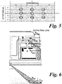
- the target performance for a TV device is specified by a calculation of uniformity which is described as the ratio between the lowest and highest luminance values. Uniformity is measured on spots which are gathered by dividing a panel into 4x4 sections as shown in Figure 5 .
- a typical, non-limiting, target uniformity of 0.75 is desired for optical criteria.
- the value of the luminance at node 5 i.e. in the centre of the 4x4 panel shown in Figure 4 ) is the highest because this node is in the middle of the area which gathers the light directly to itself. This is the luminance which will form the objective function for this embodiment of the invention.
- step 102 The method proceeds to step 102.
- Step 102 Generate data table for mechanical properties
- the mechanical design parameters are acquired and determined.
- the acquired mechanical design parameters are explained below and illustrated with reference to Figure 6 .
- bottom edge values are always separated from the values for the other edges.
- step 104 The method then proceeds to step 104.
- Step 104 Generate data table for optical properties
- step 104 the optical design parameters are acquired and determined.
- the acquired optical design parameters are explained below. It is shown in Figure 4 that steps 102 and 104 are carried out in series. However, this need not be the case and other sequences may be used.
- step 106 The method then proceeds to step 106.
- Step 106 Perform stepwise regression
- the objective function is the luminance on the node "5" (see Figure 5 ).
- a stepwise regression is performed according to design guide data.
- the method in more detail, involves checking the significance of the parameters using stepwise regression. With this method, the variance inflation factors and correlation matrices are then determined in order to avoid coincidences between parameters. Further, regression results show the relation between the optical and mechanical parameters and enable effective modelling and optimisation by assigning rules according to minimum or maximum values of parameters.
- a variable is considered for addition to or subtraction from the set of explanatory variables based on some prespecified criterion.
- criterions include: Akaike information criterion, Bayesian information criterion, Mallows's Cp, PRESS, or false discovery rate.
- This regression method is the combination of both forward selection and backward elimination.
- Forward selection starts with no variables and adds parameters one by one and stops when the point model has no improvement.
- backward elimination starts with all variables and tests the deletion of each variable one by one to get a better model fit.
- forward selection involves starting with no variables in the model, testing the addition of each variable using a chosen model fit criterion, adding the variable whose inclusion gives the most statistically significant improvement of the fit, and repeating this process until none improves the model to a statistically significant extent.
- backward elimination involves starting with all candidate variables, testing the deletion of each variable using a chosen model fit criterion, deleting the variable whose loss gives the most statistically insignificant deterioration of the model fit, and repeating this process until no further variables can be deleted without a statistically significant loss of fit.
- Bidirectional elimination includes a combination of the above, testing at each step for variables to be included or excluded.
- step 108 The method proceeds to step 108.
- Step 108 Select model
- a model is selected.
- step 110 The method proceeds to step 110.
- Step 110 Specify constraints
- constraints are applied to the model to enable solving using linear iterative methods.
- Uniformity is a constraint as described above - a target parameter with a value of "0.75". So, the suitable luminance function was checked for all other nodes as shown in Figure 5 .
- distances of parts to the active area (AA) have limitations in terms of the available and compared distances.
- Another constraint is mechanical orientation of lenses which has a restriction in terms of distance to each other (i.e. spacing between them in different dimensions). So, we can limit the number of lenses by applying the rule of,
- IDP iterative linear programming
- step 114 The method proceeds to step 114.
- Step 114 Determine optimal design
- an optimal design configuration can be determined. This can, optionally, be used in a manufacturing process to build a backlight module and display device according to the optimal design.
Landscapes
- Physics & Mathematics (AREA)
- Nonlinear Science (AREA)
- Mathematical Physics (AREA)
- Chemical & Material Sciences (AREA)
- Crystallography & Structural Chemistry (AREA)
- General Physics & Mathematics (AREA)
- Optics & Photonics (AREA)
- Devices For Indicating Variable Information By Combining Individual Elements (AREA)
- Planar Illumination Modules (AREA)
Abstract
Description
- The present invention relates to an improved modelling method for designing a flat-screen TV.
- Flat-screen televisions using liquid crystal display (LCD) panels are well known in the art. There are a number of ways to design and build such structures in an efficient and robust manner. One such method is to use a backlight module structure (BMS). The design of BMS structures includes the design of the mechanical and optical parts of a display panel and determining the optimal relations between components.
- It is known to provide certain specific configurations of display panel to ease manufacture. For example,
US2015241624A1 discloses a backlight module includes a light guiding plate, a frame element, a light bar and a light-bar cover. The light guiding plate has a light output surface. The frame element includes a bottom surface and a side wall, the bottom surface is parallel to the light output surface of the light guiding plate, and the side wall is extended from the bottom surface and towards a direction perpendicular to the light output surface to ease assembly. - However, whilst improved structures and configurations may ease manufacture, to date known arrangements and methods are not able to systematically optimise the mechanical and optical properties of an LED LCD panel to give optimal optical or mechanical properties. The present invention, in embodiments, addresses this issue.
- According to a first aspect of the present invention, there is provided a method of designing a backlight module for a flat panel display device having an liquid crystal display (LCD) panel, the method comprising the steps of: defining mechanical and optical parameters for mechanical and optical components of the display device; generating a model based at least in part on the defined mechanical and optical parameters, the model defining one or more relationships between one or more mechanical and/or optical parameters; applying constraints on the values of the mechanical and optical parameters within the model; utilising the model and said defined constraints to generate a configuration of mechanical and optical components forming a design of a backlight module which is optimised for at least one mechanical or optical criterion; and generating a design for a backlight module based on said generated configuration.
- In one embodiment, step b) comprises defining the model as one or more linear equations, and wherein step d) comprises solving said one or more linear equations to generate said configuration.
- In one embodiment, step d) comprises solving using linear iterative methods.
- In one embodiment, the at least one optical or mechanical criterion comprises luminescence.
- In one embodiment, the said luminescence is the luminescence of a specified central point of display.
- In one embodiment, the flat panel display device is an LCD panel having an LED backlight.
- In one embodiment, the LED backlight is configured and arranged, in use, to illuminate the LCD panel directly from behind.
- In one embodiment, one or more of the mechanical parameters comprises the Mechanical Distances to Active Area (AA) Borders.
- In one embodiment, said mechanical parameters comprises one or more of: the distance from a middle frame to AA line; the distance from an optic film to the AA line; the distance from a diffuser film to the AA line; the distance from a reflector sheet to the AA line; the distance from front cover to AA line; and angle of edges.
- In one embodiment, one or more of the optical parameters comprises one or more of: the number of regional lenses; and the lens ratio.
- In one embodiment, one or more mechanical constraints comprise one or more of: upper and/or lower bounds of mechanical variables; distance of mechanical parts to the active area (AA); mechanical orientation and/or spacing of lenses.
- In one embodiment, one or more of the optical constraints comprises uniformity.
- In one embodiment, step b) is based at least in part on obtained empirical mechanical and optical parameter values.
- In one embodiment, the method further comprises the step of:
producing a backlight module defined according to the generated design. - In one embodiment, the method further comprises producing a flat screen television comprising the backlight module produced according to the generated design.
- According to a second aspect of the present invention, there is provided a backlight module produced according to a design generated by the method of the first aspect.
- According to a third aspect of the present invention, there is provided a LCD display device having a backlight module according to the second aspect.
- Embodiments of the present invention will now be described in detail with reference to the accompanying drawings, in which:
-
Figure 1 is a general view of an exemplary flat-screen display device in the form of a direct light emitting diode (D-LED) television; -
Figure 2 is an exploded view of an exemplary backplane module system (BMS) for use in an exemplary flat-screen display device ofFigure 1 ; -
Figure 3 is an isometric view of an optical component element forming part of the backplane module system ofFigure 2 ; -
Figure 4 is a flowchart illustrating a method of designing a D-LED BMS for a D-LED television according to an embodiment of the present invention; -
Figure 5 is a schematic diagram showing optical parameters; and -
Figure 6 is a section view of thepanel 10 ofFigure 2 showing mechanical parameters. - The present invention relates to a method of determining an optimal configuration for a backlight module system. In embodiments, this is achieved through mathematical modelling.
- There are a large number of parameters and variables which need to be considered when designing the specification for a backlight module. In general summary, the method comprises determining these parameters and associated constraints, before defining a modelling system and exporting the defined system to linear programming software. By use of linear programming, a set of linear equations are solved to determine the optimal design for optimal optical performance of the backlight module system (BMS).
-
Figure 1 shows anexemplary display device 1 in the form of a Direct-Light Emitting Diode (D-LED) television display. Thedisplay device 1 has anouter housing 2 supported by astand 4. Adisplay panel 10 is located within theouter housing 2. - An exploded view of an
exemplary display panel 10 is shown inFigure 2 . - The
display panel 10 comprises afront screen 12, a Liquid Crystal Display (LCD)cell panel 14, amiddle frame 16, reflector anddiffuser sheet 18 and abackcover backlight unit 20. - The
front screen 12 is primarily a cosmetic frame through which the end user views the display. In addition, thefront screen 12 has encapsulation and environmental protection functions, for example, to protect theLCD cell panel 14 from damage. Therefore, thefront screen 12 is an important part of the group of components forming thepanel 10. - The
LCD cell panel 14 is at least partially formed from glass. LCDs are well known in the art and the skilled person would readily understand the general concept and operation of such a panel. In essence, theLCD cell panel 14 has a plurality of cells which are arranged to represent pixels of the display. Depending upon the electrical configuration, each cell is arranged either to transmit light or to prevent light transmission. Therefore, theLCD panel 14 is a transmissive element and requires a backlight or other light source to illuminate the display. - With regard to the
LCD cell panel 14, there is an active area (AA) which a key issue for designing the mechanical and optical properties of the panel. Optical performance criteria comprise, in general, luminance and uniformity and these are measured inside the active area line, essentially the area of the screen viewable by the end user. - The Middle
Frame 16 is, in embodiments, formed from plastic raw material such as, for example, "PC+ABS/GF %15". Resilient plastic is used in this part in order to absorb the external forces towards the cell and other optical materials. Themiddle frame 16 is located between the optical arrangement and theLCD cell panel 14 to keep these elements at an accurate distance from each other. - The
reflector sheet 18 is generally located at the bottom of the optical components. It enables the light to be reflected in an actively managed and accurate manner. - The
diffuser sheet 18 is configured to scatter light and avoid deterioration of distribution of light. Thediffuser sheet 18 comprises a plurality of internal micro spheres. Moreover, thediffuser sheet 18 ensures the flatness of the other optical components and has a thermal energy absorbing function and reduces the thermal load on other optical components. - Finally, the BC
BLU 20 is arranged to support and contain the other parts and hold them in a defined configuration with accurate spacing. Essentially, theBC BLU 20 is a housing part formed from a strong and rigid material such as hard plastic and/or metal. - The
BC BLU 20 is shown in more detail inFigure 3 . TheBC BLU 20 comprises a plurality of LED bars 22 andlenses 24. Thelenses 24 provide angular illumination or directivity. - The assembly gaps and positional and configurational relationships between both the mechanical and the optical parts mentioned above are specified by looking at some design parameters. Specification of design rules can be changed between different projects with different size preferences, according to the active area desired or used. In embodiments, the present invention relates to a method of designing a D-LED display device. In essence, the direct-LED concept is that the LED packages are located as an array directly behind the LCD screen and light passes from the LED packages directly to the screen. This is in contrast to edge-emitting LED designs where the LED devices illuminate the display screen from the side through the use of reflectors and refractors.
- Clearly, the design parameters for D-LED designs are specific to this configuration of device. However, the general operation and principles of the present invention are applicable to different display device designs and this would be readily appreciated by the skilled person.
- A method according to an embodiment of the present invention will now be described with reference to
Figure 4. Figure 4 shows a flow chart of a method for designing an optimal configuration for an D-LED display device such as thedisplay device 1 shown inFigure 1 . - The present invention provides an improved approach for designing a display device such as a LCD television by considering both the optical and the mechanical properties and optimising these properties to produce an optimal display device which is optimised for one or more parameters. In embodiments, the display device may be optimised for luminance values.
- At
step 100, the optimisation parameter is defined. This is the parameter that is intended to be solved for and optimised through the method of the present invention. - In this embodiment, the parameter is luminance. More specifically, the parameter is the luminance of
node 5 inFigure 5 as will be described below. - The optical performance of a TV is heavily influenced by the gathered luminance. Luminance is a photometric measure of the luminous intensity per unit area of light travelling in a given direction. It describes the amount of light that passes through, is emitted or reflected from a particular area, and falls within a given solid angle. The SI unit for luminance is candela per square metre (cd/m2). A non-SI term for the same unit is the "nit".
- The target performance for a TV device is specified by a calculation of uniformity which is described as the ratio between the lowest and highest luminance values. Uniformity is measured on spots which are gathered by dividing a panel into 4x4 sections as shown in
Figure 5 . The expression for luminance is shown in expression 1) below:
- A typical, non-limiting, target uniformity of 0.75 is desired for optical criteria. The value of the luminance at node 5 (i.e. in the centre of the 4x4 panel shown in
Figure 4 ) is the highest because this node is in the middle of the area which gathers the light directly to itself. This is the luminance which will form the objective function for this embodiment of the invention. - The method proceeds to step 102.
- At
step 102, the mechanical design parameters are acquired and determined. The acquired mechanical design parameters are explained below and illustrated with reference toFigure 6 . - maiy , distance from middle frame to AA line
- faiy , distance from optic films to AA line
- paiy , distance from diffuser film to AA line
- raiy , distance from reflector sheet to AA line
- k iy , distance from front cover to AA line
- bqi , angle of edges of BC BLU
- rqi , angle of edges of reflector sheet
- bi , distance from folded edge of BC BLU to AA line
- ri , distance from folded edge of reflector sheet to AA line
- i = 1 for bottom edge
- i = 2 for top edge
- i = 3,4 for right/left edge
- It is important to note that bottom edge values are always separated from the values for the other edges. "i=2" is for both top and right/left edges except the parameters b i, and r i because they must be examined for each edge independently.
- Once the relevant design parameters have been identified and appropriate determinations made for various configurations and sizes, then a table can be generated. Different TV models may have typical sizes from 32" to 75". There are mechanical parameters for each configuration.
- An example of such a table is shown in Table 1 below.

- The method then proceeds to step 104.
- At
step 104, the optical design parameters are acquired and determined. The acquired optical design parameters are explained below. It is shown inFigure 4 that steps 102 and 104 are carried out in series. However, this need not be the case and other sequences may be used. - Optical design parameters are explained below:
- Lj , # of Regional Lenses
- LUj , Luminance Values
- Optical Distance, panel depth
- Lens Luminescence Angle, angle of scattered light
- #of Total Lenses
- j = 1.. 9 for nodes gathered as shown in
figure 5 - These optical parameters can then be gathered in the manner in which the mechanical parameters are gathered in
step 102. This results in tables such as exemplary tables 2 and 3 below.Table 2 Optical Properties #of Lenses Optical Distance Lens Angle #of Led Bars #of Total Lenses L1 L2 L3 L4 L5 L6 L7 L8 L9 40.00 160,00° 2,00 22,00 4,00 3.00 4.00 8,00 6,00 8,00 4.00 3.00 4,00 40,00 160.00° 3,00 26.00 4,00 5,00 4,00 4,00 4,00 4,00 4,00 5,00 4,00 40,00 160,00° 3,00 23,00 4,00 4,00 4,00 3,00 3,00 3,00 4.00 4,00 4,00 40,00 160,00° 3,00 23,00 4,00 4,00 4,00 3.00 3,00 3,00 4,00 4,00 4,00 40,00 160,00° 4,00 28,00 6,00 6,00 6,00 6,00 6,00 6,00 6.00 6,00 6,00 40,00 160,00° 6,00 30.00 6,00 8,00 6,00 9,00 12,00 9,00 6.00 8,00 6,00 40,00 160.00° 6,00 30,00 6,00 8,00 6,00 9,00 12,00 9,00 6,00 8,00 6,00 40,00 160,00° 6,00 30,00 6,00 8,00 6.00 9.00 12.00 9,00 6,00 8,00 6,00 40,00 160,00° 6,00 42,00 9,00 9,00 9,00 12,00 12,00 12,00 9,00 9,00 9,00 15,00 172.00° 10.00 50,00 10,00 12,00 10,00 15,00 18,00 15,00 10,00 12,00 10,00 15,00 172,00° 10,00 50,00 12.00 12,00 12,00 15,00 18,00 15,00 12,00 12,00 12.00 15,00 172,00° 6,00 68,00 16,00 20,00 16,00 22,00 26,00 22,00 16,00 20,00 16,00 15,00 172,00° 12,00 84,00 18,00 18,00 18,00 30,00 30.00 30,00 18,00 18,00 18,00 40,00 160,00° 3,00 27,00 4.00 5,00 4,00 4,00 5,00 4,00 4,00 5,00 4,00 40,00 160,00° 4,00 34,00 8,00 9,00 8,00 8,00 10,00 8,00 8,00 9,00 8,00 40,00 160,00° 6,00 42,00 9,00 12,00 9,00 15,00 20,90 15,00 9,00 12,00 9,00 40,00 160,00° 6,00 42,00 9,00 12,00 9,00 15,00 20,00 15,00 9.00 12,00 9.00 40,00 160.00° 6,00 52,00 10,00 16.00 10,00 16,00 18,00 16,00 10,00 16,00 10,00 30,00 160.00° 11.00 78,00 15,00 16,00 15,00 15,00 16,00 15,00 15,00 16,00 15,00 30,00 160.00° 13.00 116,00 24,00 28,00 24,00 30,00 34.00 30,00 24,00 28,00 24,00 25,00 160.00° 4.00 36,00 9.00 10,00 9.00 10,00 12,00 10,00 9.00 10,00 9.00 25,00 160,00° 8,00 48,00 12,00 12,00 12,00 16,00 16,00 16,00 12,00 12,00 12.00 25,00 160,00° 9.00 54,00 12,00 15,00 12,00 16,00 20,00 16,00 12,00 15,00 12,00 Table 3 Optical Properties #of Lenses Optical Distance Lens Angle #of Led Bars #of Total Lenses L1 L2 L3 L4 L5 L6 L7 L8 L9 40,00 160,00° 2,00 22,00 4,00 3,00 4,00 8,00 6,00 8,00 4,00 3,00 4,00 40,00 160,00° 3,00 26,00 4,00 5,00 4,00 4,00 4,00 4,00 4,00 5,00 4,00 40,00 160,00° 3,00 23,00 4,00 4,00 4,00 3,00 3,00 3,00 4,00 4,00 4,00 40,00 160,00° 3,00 23,00 4,00 4,00 4,00 3,00 3,00 3,00 4,00 4,00 4,00 40,00 160,00° 4,00 28,00 6,00 6,00 6,00 6,00 6,00 6,00 6,00 6,00 6,00 40,00 160,00° 6,00 30,00 6,00 8,00 6,00 9,00 12,00 9,00 6,00 8,00 6,00 40,00 160,00° 6,00 30,00 6,00 8,00 6,00 9,00 12,00 9,00 6,00 8,00 6,00 40,00 160,00° 6,00 30,00 6,00 8,00 6,00 9,00 12,00 9,00 6,00 8,00 6,00 40,00 160,00° 6,00 42,00 9,00 9,00 9,00 12,00 12,00 12,00 9,00 9,00 9,00 15,00 172,00° 10,00 50,00 10,00 12,00 10,00 15,00 18,00 15,00 10,00 12,00 10,00 15,00 172,00° 10,00 50,00 12,00 12,00 12,00 15,00 18,00 15,00 12,00 12,00 12,00 15,00 172,00° 6,00 68,00 16,00 20,00 16,00 22,00 26,00 22,00 16,00 20,00 16,00 15,00 172,00° 12,00 84,00 18,00 18,00 18,00 30,00 30,00 30,00 18,00 18,00 18,00 40,00 160,00° 3,00 27,00 4,00 5,00 4,00 4,00 5,00 4,00 4,00 5,00 4,00 40,00 160,00° 4,00 34,00 8,00 9,00 8,00 8,00 10,00 8,00 8,00 9,00 8,00 40,00 160,00° 6,00 42,00 9,00 12,00 9,00 15,00 20,00 15,00 9,00 12,00 9,00 40,00 160,00° 6,00 42,00 9,00 12,00 9,00 15,00 20,00 15,00 9,00 12,00 9,00 40,00 160,00° 6,00 52,00 10,00 16,00 10,00 16,00 18,00 16,00 10,00 16,00 10,00 30,00 160,00° 11,00 78,00 15,00 16,00 15,00 15,00 16,00 15,00 15,00 16,00 15,00 30,00 160,00° 13,00 116,00 24,00 28,00 24,00 30,00 34,00 30,00 24,00 28,00 24,00 25,00 160,00° 4,00 36,00 9,00 10,00 9,00 10,00 12,00 10,00 9,00 10,00 9,00 25,00 160,00° 8,00 48,00 12,00 12,00 12,00 16,00 16,00 16,00 12,00 12,00 12,00 25,00 160,00° 9,00 54,00 12,00 15,00 12,00 16,00 20,00 16,00 12,00 15,00 12,00 - The method then proceeds to step 106.
- There are many DLED TV projects that are designed from sizes 32" to 75". The mechanical and optical parameters have been obtained as shown in Tables 1 to 3 above.
- The objective function is the luminance on the node "5" (see
Figure 5 ). In order to check significance of decision variables, a stepwise regression is performed according to design guide data. - The method, in more detail, involves checking the significance of the parameters using stepwise regression. With this method, the variance inflation factors and correlation matrices are then determined in order to avoid coincidences between parameters. Further, regression results show the relation between the optical and mechanical parameters and enable effective modelling and optimisation by assigning rules according to minimum or maximum values of parameters.
- In each step of the regression, a variable is considered for addition to or subtraction from the set of explanatory variables based on some prespecified criterion.
- This may be based on any number of criterions. Common criterions include: Akaike information criterion, Bayesian information criterion, Mallows's Cp, PRESS, or false discovery rate.
- This regression method according to an embodiment is the combination of both forward selection and backward elimination. Forward selection starts with no variables and adds parameters one by one and stops when the point model has no improvement. In contrary, backward elimination starts with all variables and tests the deletion of each variable one by one to get a better model fit.
- In other words, forward selection involves starting with no variables in the model, testing the addition of each variable using a chosen model fit criterion, adding the variable whose inclusion gives the most statistically significant improvement of the fit, and repeating this process until none improves the model to a statistically significant extent.
- In contrast, backward elimination involves starting with all candidate variables, testing the deletion of each variable using a chosen model fit criterion, deleting the variable whose loss gives the most statistically insignificant deterioration of the model fit, and repeating this process until no further variables can be deleted without a statistically significant loss of fit.
- Bidirectional elimination includes a combination of the above, testing at each step for variables to be included or excluded.
- By doing stepwise regression, a large number of results are obtained.
- The method proceeds to step 108.
- Based on the stepwise regression in
step 106, a model is selected. - There are models having different number of variables but we selected the models having 6. It shows us more relations of parameters in a panel.
- Finally, we selected models according to their;
- adjusted R2 values desired as much as possible,
- AlC values desired as low as possible
- TestMAPE values desired as low as possible
- coef-pvalues-max lower than 0.05,
- pvalue lower than 0.05,
- vif-max lover than 6
- In addition, designer empirical knowledge is also an important criteria for selection of models because the closer to real possible influence the better the results obtained from the mathematical model.
- Thus, the final selected objective function is appeared as written below in expression 2):

- The method proceeds to step 110.
- At
step 110, constraints are applied to the model to enable solving using linear iterative methods. - Uniformity is a constraint as described above - a target parameter with a value of "0.75". So, the suitable luminance function was checked for all other nodes as shown in
Figure 5 . - These are shown below;




- Furthermore, upper and lower bounds of mechanical variables comprise additional constraints.
- Moreover, distances of parts to the active area (AA) have limitations in terms of the available and compared distances.
- Another constraint is mechanical orientation of lenses which has a restriction in terms of distance to each other (i.e. spacing between them in different dimensions). So, we can limit the number of lenses by applying the rule of,
- xmin =85.00 mm
- ymin= 42.50 mm
- Finally, the lens ratio can be used as a constraint:

- Once the model is defined with constraints, iterative linear programming (ILP) tools can be utilised to solve the system for optimal values of the design.
- The method proceeds to step 114.
- Once the parameters have been obtained in
step 114, an optimal design configuration can be determined. This can, optionally, be used in a manufacturing process to build a backlight module and display device according to the optimal design. - It is also intended that the present invention covers a backlight module made to the design created by the above steps.
- Embodiments of the present invention have been described with particular reference to the examples illustrated. While specific examples are shown in the drawings and are herein described in detail, it should be understood, however, that the drawings and detailed description are not intended to limit the invention to the particular form disclosed. It will be appreciated that variations and modifications may be made to the examples described within the scope of the present invention.

Claims (15)
- A method of designing a backlight module for a flat panel display device having an liquid crystal display (LCD) panel, the method comprising the steps of:a) defining mechanical and optical parameters for mechanical and optical components of the display device;b) generating a model based at least in part on the defined mechanical and optical parameters, the model defining one or more relationships between one or more mechanical and/or optical parameters;c) applying constraints on the values of the mechanical and optical parameters within the model;d) utilising the model and said defined constraints to generate a configuration of mechanical and optical components forming a design of a backlight module which is optimised for at least one mechanical or optical criterion; ande) generating a design for a backlight module based on said generated configuration.
- A method according to claim 1, wherein step b) comprises defining the model as one or more linear equations, and wherein step d) comprises solving said one or more linear equations to generate said configuration.
- A method according to claim 2, wherein step d) comprises solving using linear iterative methods.
- A method according to claim 1, 2 or 3, wherein the at least one optical or mechanical criterion comprises luminescence.
- A method according to claim 4, wherein the said luminescence is the luminescence of a specified central point of display.
- A method according to any one of the preceding claims, wherein the flat panel display device is an LCD panel having an LED backlight.
- A method according to claim 6, wherein the LED backlight is configured and arranged, in use, to illuminate the LCD panel directly from behind.
- A method according to any one of the preceding claims, wherein one or more of the mechanical parameters comprises the Mechanical Distances to Active Area (AA) Borders; the distance from a middle frame to AA line; the distance from an optic film to the AA line; the distance from a diffuser film to the AA line; the distance from a reflector sheet to the AA line; the distance from front cover to AA line; and the angle of edges.
- A method according to any one of the preceding claims, wherein one or more of the optical parameters comprises one or more of: the number of regional lenses; and the lens ratio.
- A method according to any one of the preceding claims, wherein one or more mechanical constraints comprise one or more of: upper and/or lower bounds of mechanical variables; distance of mechanical parts to the active area (AA); mechanical orientation and/or spacing of lenses.
- A method according to any one of the preceding claims, wherein one or more of the optical constraints comprises uniformity of light emission.
- A method according to any one of the preceding claims, wherein step b) is based at least in part on obtained empirical mechanical and optical parameter values.
- A method according to any one of the preceding claims, further comprising the step of:f) producing a backlight module defined according to the generated design.
- A backlight module produced according to a design generated by the method of any one of claims 1 to 13.
- An LCD display device having a backlight module according to claim 14.
Priority Applications (2)
| Application Number | Priority Date | Filing Date | Title |
|---|---|---|---|
| EP17209061.5A EP3502773B1 (en) | 2017-12-20 | 2017-12-20 | An improved modelling method for designing a backlight module for a flat-screen television |
| TR2017/22881A TR201722881A2 (en) | 2017-12-20 | 2017-12-29 | AN IMPROVED MODELING METHOD FOR DESIGNING A FLAT SCREEN TELEVISION |
Applications Claiming Priority (1)
| Application Number | Priority Date | Filing Date | Title |
|---|---|---|---|
| EP17209061.5A EP3502773B1 (en) | 2017-12-20 | 2017-12-20 | An improved modelling method for designing a backlight module for a flat-screen television |
Publications (2)
| Publication Number | Publication Date |
|---|---|
| EP3502773A1 true EP3502773A1 (en) | 2019-06-26 |
| EP3502773B1 EP3502773B1 (en) | 2024-07-17 |
Family
ID=60702407
Family Applications (1)
| Application Number | Title | Priority Date | Filing Date |
|---|---|---|---|
| EP17209061.5A Active EP3502773B1 (en) | 2017-12-20 | 2017-12-20 | An improved modelling method for designing a backlight module for a flat-screen television |
Country Status (2)
| Country | Link |
|---|---|
| EP (1) | EP3502773B1 (en) |
| TR (1) | TR201722881A2 (en) |
Citations (2)
| Publication number | Priority date | Publication date | Assignee | Title |
|---|---|---|---|---|
| US20100020264A1 (en) * | 2008-07-24 | 2010-01-28 | Shingo Ohkawa | Light emitting device assembly, surface light source device, liquid crystal display device assembly, and light output member |
| US20150241624A1 (en) | 2014-02-27 | 2015-08-27 | Innolux Corporation | Backlight module |
-
2017
- 2017-12-20 EP EP17209061.5A patent/EP3502773B1/en active Active
- 2017-12-29 TR TR2017/22881A patent/TR201722881A2/en unknown
Patent Citations (2)
| Publication number | Priority date | Publication date | Assignee | Title |
|---|---|---|---|---|
| US20100020264A1 (en) * | 2008-07-24 | 2010-01-28 | Shingo Ohkawa | Light emitting device assembly, surface light source device, liquid crystal display device assembly, and light output member |
| US20150241624A1 (en) | 2014-02-27 | 2015-08-27 | Innolux Corporation | Backlight module |
Non-Patent Citations (2)
| Title |
|---|
| CHEN Y ET AL: "Design of a backlight module with a freeform surface by applying the Taguchi method", CHINESE OPTICS LETTERS, CHINESE OPTICAL SOCIETY, CN, vol. 13, no. 3, 032302, 10 March 2015 (2015-03-10), pages 032302-1 - 032302-5, XP009505048, ISSN: 1671-7694 * |
| LUMILEDS: "Technical Datasheet DS25 Luxeon Emitter", 1 January 2005 (2005-01-01), USA, pages 1 - 19, XP055275056, Retrieved from the Internet <URL:https://www.sparkfun.com/datasheets/Components/Luxeon-I.pdf> [retrieved on 20160524] * |
Also Published As
| Publication number | Publication date |
|---|---|
| EP3502773B1 (en) | 2024-07-17 |
| TR201722881A2 (en) | 2019-07-22 |
Similar Documents
| Publication | Publication Date | Title |
|---|---|---|
| JP6553280B2 (en) | Screen for free and limited operation modes | |
| EP3200006A1 (en) | Head-up display device | |
| JP2020517979A (en) | Directional backlight, backlit display and method | |
| US7722238B2 (en) | Light source device, display using same, and terminal device | |
| CN110741313A (en) | Display screen with free view mode and limited view mode and application thereof | |
| CN103578360B (en) | Display device | |
| JP2020516928A (en) | Multi-layer multi-view display and method | |
| JP2020507798A (en) | Static multi-view display and method | |
| TW201421076A (en) | Light source device, display unit, and electronic apparatus | |
| CN114286954B (en) | Faceted diffusers that provide a specific light distribution from a light source | |
| US20110038178A1 (en) | Planar illumination device | |
| US20200322590A1 (en) | Cross-render multiview camera, system, and method | |
| CN110133905A (en) | Backlight module and head up display | |
| US11428860B2 (en) | Static multiview display and method employing directional light source and horizontal diffuser | |
| KR20170134617A (en) | Texture gradient for uniform light output from transparent backlight | |
| CN103782082A (en) | Light guide plate, surface light source device, and transmissive image display device | |
| EP3502773B1 (en) | An improved modelling method for designing a backlight module for a flat-screen television | |
| JP7317140B2 (en) | Static multi-view display and method with diagonal parallax | |
| KR20080018728A (en) | Light unit and display device using same | |
| JP2013206595A (en) | Light guide plate and lighting device as well as display device using light guide plate | |
| KR102444400B1 (en) | Double-sided display device and backlight unit therefor | |
| CN110308581B (en) | Liquid crystal dimming film, backlight module and manufacturing method of liquid crystal dimming film | |
| JP5157022B2 (en) | Light guide device and backlight module | |
| TWI465778B (en) | A light control panel, a surface light source device, and a transmission type image display device | |
| CN223711863U (en) | Reverse prism sheet and backlight module with it, liquid crystal display device |
Legal Events
| Date | Code | Title | Description |
|---|---|---|---|
| PUAI | Public reference made under article 153(3) epc to a published international application that has entered the european phase |
Free format text: ORIGINAL CODE: 0009012 |
|
| STAA | Information on the status of an ep patent application or granted ep patent |
Free format text: STATUS: THE APPLICATION HAS BEEN PUBLISHED |
|
| AK | Designated contracting states |
Kind code of ref document: A1 Designated state(s): AL AT BE BG CH CY CZ DE DK EE ES FI FR GB GR HR HU IE IS IT LI LT LU LV MC MK MT NL NO PL PT RO RS SE SI SK SM TR |
|
| AX | Request for extension of the european patent |
Extension state: BA ME |
|
| STAA | Information on the status of an ep patent application or granted ep patent |
Free format text: STATUS: REQUEST FOR EXAMINATION WAS MADE |
|
| 17P | Request for examination filed |
Effective date: 20191223 |
|
| RBV | Designated contracting states (corrected) |
Designated state(s): AL AT BE BG CH CY CZ DE DK EE ES FI FR GB GR HR HU IE IS IT LI LT LU LV MC MK MT NL NO PL PT RO RS SE SI SK SM TR |
|
| STAA | Information on the status of an ep patent application or granted ep patent |
Free format text: STATUS: EXAMINATION IS IN PROGRESS |
|
| 17Q | First examination report despatched |
Effective date: 20211130 |
|
| GRAP | Despatch of communication of intention to grant a patent |
Free format text: ORIGINAL CODE: EPIDOSNIGR1 |
|
| STAA | Information on the status of an ep patent application or granted ep patent |
Free format text: STATUS: GRANT OF PATENT IS INTENDED |
|
| INTG | Intention to grant announced |
Effective date: 20240423 |
|
| RIN1 | Information on inventor provided before grant (corrected) |
Inventor name: ALBEY, ERINC Inventor name: YANIKOGLU, IHSAN Inventor name: KURT, OLKAN |
|
| GRAS | Grant fee paid |
Free format text: ORIGINAL CODE: EPIDOSNIGR3 |
|
| GRAA | (expected) grant |
Free format text: ORIGINAL CODE: 0009210 |
|
| STAA | Information on the status of an ep patent application or granted ep patent |
Free format text: STATUS: THE PATENT HAS BEEN GRANTED |
|
| AK | Designated contracting states |
Kind code of ref document: B1 Designated state(s): AL AT BE BG CH CY CZ DE DK EE ES FI FR GB GR HR HU IE IS IT LI LT LU LV MC MK MT NL NO PL PT RO RS SE SI SK SM TR |
|
| REG | Reference to a national code |
Ref country code: GB Ref legal event code: FG4D |
|
| REG | Reference to a national code |
Ref country code: CH Ref legal event code: EP |
|
| REG | Reference to a national code |
Ref country code: DE Ref legal event code: R096 Ref document number: 602017083329 Country of ref document: DE |
|
| REG | Reference to a national code |
Ref country code: IE Ref legal event code: FG4D |
|
| REG | Reference to a national code |
Ref country code: LT Ref legal event code: MG9D |
|
| REG | Reference to a national code |
Ref country code: NL Ref legal event code: MP Effective date: 20240717 |
|
| PG25 | Lapsed in a contracting state [announced via postgrant information from national office to epo] |
Ref country code: PT Free format text: LAPSE BECAUSE OF FAILURE TO SUBMIT A TRANSLATION OF THE DESCRIPTION OR TO PAY THE FEE WITHIN THE PRESCRIBED TIME-LIMIT Effective date: 20241118 |
|
| REG | Reference to a national code |
Ref country code: AT Ref legal event code: MK05 Ref document number: 1704702 Country of ref document: AT Kind code of ref document: T Effective date: 20240717 |
|
| PG25 | Lapsed in a contracting state [announced via postgrant information from national office to epo] |
Ref country code: NL Free format text: LAPSE BECAUSE OF FAILURE TO SUBMIT A TRANSLATION OF THE DESCRIPTION OR TO PAY THE FEE WITHIN THE PRESCRIBED TIME-LIMIT Effective date: 20240717 |
|
| PG25 | Lapsed in a contracting state [announced via postgrant information from national office to epo] |
Ref country code: PT Free format text: LAPSE BECAUSE OF FAILURE TO SUBMIT A TRANSLATION OF THE DESCRIPTION OR TO PAY THE FEE WITHIN THE PRESCRIBED TIME-LIMIT Effective date: 20241118 Ref country code: NL Free format text: LAPSE BECAUSE OF FAILURE TO SUBMIT A TRANSLATION OF THE DESCRIPTION OR TO PAY THE FEE WITHIN THE PRESCRIBED TIME-LIMIT Effective date: 20240717 |
|
| PG25 | Lapsed in a contracting state [announced via postgrant information from national office to epo] |
Ref country code: NO Free format text: LAPSE BECAUSE OF FAILURE TO SUBMIT A TRANSLATION OF THE DESCRIPTION OR TO PAY THE FEE WITHIN THE PRESCRIBED TIME-LIMIT Effective date: 20241017 |
|
| PG25 | Lapsed in a contracting state [announced via postgrant information from national office to epo] |
Ref country code: FI Free format text: LAPSE BECAUSE OF FAILURE TO SUBMIT A TRANSLATION OF THE DESCRIPTION OR TO PAY THE FEE WITHIN THE PRESCRIBED TIME-LIMIT Effective date: 20240717 Ref country code: GR Free format text: LAPSE BECAUSE OF FAILURE TO SUBMIT A TRANSLATION OF THE DESCRIPTION OR TO PAY THE FEE WITHIN THE PRESCRIBED TIME-LIMIT Effective date: 20241018 Ref country code: PL Free format text: LAPSE BECAUSE OF FAILURE TO SUBMIT A TRANSLATION OF THE DESCRIPTION OR TO PAY THE FEE WITHIN THE PRESCRIBED TIME-LIMIT Effective date: 20240717 |
|
| PG25 | Lapsed in a contracting state [announced via postgrant information from national office to epo] |
Ref country code: BG Free format text: LAPSE BECAUSE OF FAILURE TO SUBMIT A TRANSLATION OF THE DESCRIPTION OR TO PAY THE FEE WITHIN THE PRESCRIBED TIME-LIMIT Effective date: 20240717 |
|
| PG25 | Lapsed in a contracting state [announced via postgrant information from national office to epo] |
Ref country code: LV Free format text: LAPSE BECAUSE OF FAILURE TO SUBMIT A TRANSLATION OF THE DESCRIPTION OR TO PAY THE FEE WITHIN THE PRESCRIBED TIME-LIMIT Effective date: 20240717 |
|
| PG25 | Lapsed in a contracting state [announced via postgrant information from national office to epo] |
Ref country code: IS Free format text: LAPSE BECAUSE OF FAILURE TO SUBMIT A TRANSLATION OF THE DESCRIPTION OR TO PAY THE FEE WITHIN THE PRESCRIBED TIME-LIMIT Effective date: 20241117 Ref country code: AT Free format text: LAPSE BECAUSE OF FAILURE TO SUBMIT A TRANSLATION OF THE DESCRIPTION OR TO PAY THE FEE WITHIN THE PRESCRIBED TIME-LIMIT Effective date: 20240717 |
|
| PG25 | Lapsed in a contracting state [announced via postgrant information from national office to epo] |
Ref country code: HR Free format text: LAPSE BECAUSE OF FAILURE TO SUBMIT A TRANSLATION OF THE DESCRIPTION OR TO PAY THE FEE WITHIN THE PRESCRIBED TIME-LIMIT Effective date: 20240717 |
|
| PG25 | Lapsed in a contracting state [announced via postgrant information from national office to epo] |
Ref country code: ES Free format text: LAPSE BECAUSE OF FAILURE TO SUBMIT A TRANSLATION OF THE DESCRIPTION OR TO PAY THE FEE WITHIN THE PRESCRIBED TIME-LIMIT Effective date: 20240717 Ref country code: RS Free format text: LAPSE BECAUSE OF FAILURE TO SUBMIT A TRANSLATION OF THE DESCRIPTION OR TO PAY THE FEE WITHIN THE PRESCRIBED TIME-LIMIT Effective date: 20241017 |
|
| PG25 | Lapsed in a contracting state [announced via postgrant information from national office to epo] |
Ref country code: RS Free format text: LAPSE BECAUSE OF FAILURE TO SUBMIT A TRANSLATION OF THE DESCRIPTION OR TO PAY THE FEE WITHIN THE PRESCRIBED TIME-LIMIT Effective date: 20241017 Ref country code: PL Free format text: LAPSE BECAUSE OF FAILURE TO SUBMIT A TRANSLATION OF THE DESCRIPTION OR TO PAY THE FEE WITHIN THE PRESCRIBED TIME-LIMIT Effective date: 20240717 Ref country code: NO Free format text: LAPSE BECAUSE OF FAILURE TO SUBMIT A TRANSLATION OF THE DESCRIPTION OR TO PAY THE FEE WITHIN THE PRESCRIBED TIME-LIMIT Effective date: 20241017 Ref country code: LV Free format text: LAPSE BECAUSE OF FAILURE TO SUBMIT A TRANSLATION OF THE DESCRIPTION OR TO PAY THE FEE WITHIN THE PRESCRIBED TIME-LIMIT Effective date: 20240717 Ref country code: IS Free format text: LAPSE BECAUSE OF FAILURE TO SUBMIT A TRANSLATION OF THE DESCRIPTION OR TO PAY THE FEE WITHIN THE PRESCRIBED TIME-LIMIT Effective date: 20241117 Ref country code: HR Free format text: LAPSE BECAUSE OF FAILURE TO SUBMIT A TRANSLATION OF THE DESCRIPTION OR TO PAY THE FEE WITHIN THE PRESCRIBED TIME-LIMIT Effective date: 20240717 Ref country code: GR Free format text: LAPSE BECAUSE OF FAILURE TO SUBMIT A TRANSLATION OF THE DESCRIPTION OR TO PAY THE FEE WITHIN THE PRESCRIBED TIME-LIMIT Effective date: 20241018 Ref country code: FI Free format text: LAPSE BECAUSE OF FAILURE TO SUBMIT A TRANSLATION OF THE DESCRIPTION OR TO PAY THE FEE WITHIN THE PRESCRIBED TIME-LIMIT Effective date: 20240717 Ref country code: ES Free format text: LAPSE BECAUSE OF FAILURE TO SUBMIT A TRANSLATION OF THE DESCRIPTION OR TO PAY THE FEE WITHIN THE PRESCRIBED TIME-LIMIT Effective date: 20240717 Ref country code: BG Free format text: LAPSE BECAUSE OF FAILURE TO SUBMIT A TRANSLATION OF THE DESCRIPTION OR TO PAY THE FEE WITHIN THE PRESCRIBED TIME-LIMIT Effective date: 20240717 Ref country code: AT Free format text: LAPSE BECAUSE OF FAILURE TO SUBMIT A TRANSLATION OF THE DESCRIPTION OR TO PAY THE FEE WITHIN THE PRESCRIBED TIME-LIMIT Effective date: 20240717 |
|
| PG25 | Lapsed in a contracting state [announced via postgrant information from national office to epo] |
Ref country code: SM Free format text: LAPSE BECAUSE OF FAILURE TO SUBMIT A TRANSLATION OF THE DESCRIPTION OR TO PAY THE FEE WITHIN THE PRESCRIBED TIME-LIMIT Effective date: 20240717 Ref country code: RO Free format text: LAPSE BECAUSE OF FAILURE TO SUBMIT A TRANSLATION OF THE DESCRIPTION OR TO PAY THE FEE WITHIN THE PRESCRIBED TIME-LIMIT Effective date: 20240717 Ref country code: DK Free format text: LAPSE BECAUSE OF FAILURE TO SUBMIT A TRANSLATION OF THE DESCRIPTION OR TO PAY THE FEE WITHIN THE PRESCRIBED TIME-LIMIT Effective date: 20240717 |
|
| REG | Reference to a national code |
Ref country code: DE Ref legal event code: R097 Ref document number: 602017083329 Country of ref document: DE |
|
| PG25 | Lapsed in a contracting state [announced via postgrant information from national office to epo] |
Ref country code: EE Free format text: LAPSE BECAUSE OF FAILURE TO SUBMIT A TRANSLATION OF THE DESCRIPTION OR TO PAY THE FEE WITHIN THE PRESCRIBED TIME-LIMIT Effective date: 20240717 |
|
| PG25 | Lapsed in a contracting state [announced via postgrant information from national office to epo] |
Ref country code: CZ Free format text: LAPSE BECAUSE OF FAILURE TO SUBMIT A TRANSLATION OF THE DESCRIPTION OR TO PAY THE FEE WITHIN THE PRESCRIBED TIME-LIMIT Effective date: 20240717 |
|
| PG25 | Lapsed in a contracting state [announced via postgrant information from national office to epo] |
Ref country code: SK Free format text: LAPSE BECAUSE OF FAILURE TO SUBMIT A TRANSLATION OF THE DESCRIPTION OR TO PAY THE FEE WITHIN THE PRESCRIBED TIME-LIMIT Effective date: 20240717 |
|
| PLBE | No opposition filed within time limit |
Free format text: ORIGINAL CODE: 0009261 |
|
| STAA | Information on the status of an ep patent application or granted ep patent |
Free format text: STATUS: NO OPPOSITION FILED WITHIN TIME LIMIT |
|
| 26N | No opposition filed |
Effective date: 20250422 |
|
| PG25 | Lapsed in a contracting state [announced via postgrant information from national office to epo] |
Ref country code: MC Free format text: LAPSE BECAUSE OF FAILURE TO SUBMIT A TRANSLATION OF THE DESCRIPTION OR TO PAY THE FEE WITHIN THE PRESCRIBED TIME-LIMIT Effective date: 20240717 |
|
| PGFP | Annual fee paid to national office [announced via postgrant information from national office to epo] |
Ref country code: GB Payment date: 20250627 Year of fee payment: 8 |
|
| REG | Reference to a national code |
Ref country code: CH Ref legal event code: PL |
|
| PG25 | Lapsed in a contracting state [announced via postgrant information from national office to epo] |
Ref country code: LU Free format text: LAPSE BECAUSE OF NON-PAYMENT OF DUE FEES Effective date: 20241220 |
|
| PG25 | Lapsed in a contracting state [announced via postgrant information from national office to epo] |
Ref country code: SE Free format text: LAPSE BECAUSE OF FAILURE TO SUBMIT A TRANSLATION OF THE DESCRIPTION OR TO PAY THE FEE WITHIN THE PRESCRIBED TIME-LIMIT Effective date: 20240717 |
|
| REG | Reference to a national code |
Ref country code: BE Ref legal event code: MM Effective date: 20241231 |
|
| PGFP | Annual fee paid to national office [announced via postgrant information from national office to epo] |
Ref country code: DE Payment date: 20250627 Year of fee payment: 8 |
|
| PG25 | Lapsed in a contracting state [announced via postgrant information from national office to epo] |
Ref country code: BE Free format text: LAPSE BECAUSE OF NON-PAYMENT OF DUE FEES Effective date: 20241231 |
|
| PG25 | Lapsed in a contracting state [announced via postgrant information from national office to epo] |
Ref country code: FR Free format text: LAPSE BECAUSE OF NON-PAYMENT OF DUE FEES Effective date: 20241231 |
|
| PG25 | Lapsed in a contracting state [announced via postgrant information from national office to epo] |
Ref country code: CH Free format text: LAPSE BECAUSE OF NON-PAYMENT OF DUE FEES Effective date: 20241231 |
|
| PG25 | Lapsed in a contracting state [announced via postgrant information from national office to epo] |
Ref country code: IE Free format text: LAPSE BECAUSE OF NON-PAYMENT OF DUE FEES Effective date: 20241220 |
|
| PGFP | Annual fee paid to national office [announced via postgrant information from national office to epo] |
Ref country code: TR Payment date: 20251210 Year of fee payment: 9 |
|
| PG25 | Lapsed in a contracting state [announced via postgrant information from national office to epo] |
Ref country code: IT Free format text: LAPSE BECAUSE OF FAILURE TO SUBMIT A TRANSLATION OF THE DESCRIPTION OR TO PAY THE FEE WITHIN THE PRESCRIBED TIME-LIMIT Effective date: 20240717 |
|
| PG25 | Lapsed in a contracting state [announced via postgrant information from national office to epo] |
Ref country code: CY Free format text: LAPSE BECAUSE OF FAILURE TO SUBMIT A TRANSLATION OF THE DESCRIPTION OR TO PAY THE FEE WITHIN THE PRESCRIBED TIME-LIMIT Effective date: 20240717 |
|
| PG25 | Lapsed in a contracting state [announced via postgrant information from national office to epo] |
Ref country code: HU Free format text: LAPSE BECAUSE OF FAILURE TO SUBMIT A TRANSLATION OF THE DESCRIPTION OR TO PAY THE FEE WITHIN THE PRESCRIBED TIME-LIMIT; INVALID AB INITIO Effective date: 20171220 |
|
| PG25 | Lapsed in a contracting state [announced via postgrant information from national office to epo] |
Ref country code: SI Free format text: LAPSE BECAUSE OF FAILURE TO SUBMIT A TRANSLATION OF THE DESCRIPTION OR TO PAY THE FEE WITHIN THE PRESCRIBED TIME-LIMIT Effective date: 20240717 |
|
| PG25 | Lapsed in a contracting state [announced via postgrant information from national office to epo] |
Ref country code: LT Free format text: LAPSE BECAUSE OF FAILURE TO SUBMIT A TRANSLATION OF THE DESCRIPTION OR TO PAY THE FEE WITHIN THE PRESCRIBED TIME-LIMIT Effective date: 20240717 |