EP3502766A1 - Projection apparatus - Google Patents
Projection apparatus Download PDFInfo
- Publication number
- EP3502766A1 EP3502766A1 EP18212104.6A EP18212104A EP3502766A1 EP 3502766 A1 EP3502766 A1 EP 3502766A1 EP 18212104 A EP18212104 A EP 18212104A EP 3502766 A1 EP3502766 A1 EP 3502766A1
- Authority
- EP
- European Patent Office
- Prior art keywords
- prism
- projection apparatus
- illumination
- image
- illumination beam
- Prior art date
- Legal status (The legal status is an assumption and is not a legal conclusion. Google has not performed a legal analysis and makes no representation as to the accuracy of the status listed.)
- Granted
Links
Images

Classifications
-
- G—PHYSICS
- G03—PHOTOGRAPHY; CINEMATOGRAPHY; ANALOGOUS TECHNIQUES USING WAVES OTHER THAN OPTICAL WAVES; ELECTROGRAPHY; HOLOGRAPHY
- G03B—APPARATUS OR ARRANGEMENTS FOR TAKING PHOTOGRAPHS OR FOR PROJECTING OR VIEWING THEM; APPARATUS OR ARRANGEMENTS EMPLOYING ANALOGOUS TECHNIQUES USING WAVES OTHER THAN OPTICAL WAVES; ACCESSORIES THEREFOR
- G03B21/00—Projectors or projection-type viewers; Accessories therefor
- G03B21/14—Details
- G03B21/20—Lamp housings
- G03B21/208—Homogenising, shaping of the illumination light
-
- G—PHYSICS
- G02—OPTICS
- G02B—OPTICAL ELEMENTS, SYSTEMS OR APPARATUS
- G02B27/00—Optical systems or apparatus not provided for by any of the groups G02B1/00 - G02B26/00, G02B30/00
- G02B27/01—Head-up displays
- G02B27/017—Head mounted
- G02B27/0172—Head mounted characterised by optical features
-
- G—PHYSICS
- G02—OPTICS
- G02B—OPTICAL ELEMENTS, SYSTEMS OR APPARATUS
- G02B27/00—Optical systems or apparatus not provided for by any of the groups G02B1/00 - G02B26/00, G02B30/00
- G02B27/09—Beam shaping, e.g. changing the cross-sectional area, not otherwise provided for
- G02B27/0938—Using specific optical elements
- G02B27/095—Refractive optical elements
- G02B27/0955—Lenses
- G02B27/0961—Lens arrays
-
- G—PHYSICS
- G02—OPTICS
- G02B—OPTICAL ELEMENTS, SYSTEMS OR APPARATUS
- G02B27/00—Optical systems or apparatus not provided for by any of the groups G02B1/00 - G02B26/00, G02B30/00
- G02B27/09—Beam shaping, e.g. changing the cross-sectional area, not otherwise provided for
- G02B27/0938—Using specific optical elements
- G02B27/0988—Diaphragms, spatial filters, masks for removing or filtering a part of the beam
-
- G—PHYSICS
- G03—PHOTOGRAPHY; CINEMATOGRAPHY; ANALOGOUS TECHNIQUES USING WAVES OTHER THAN OPTICAL WAVES; ELECTROGRAPHY; HOLOGRAPHY
- G03B—APPARATUS OR ARRANGEMENTS FOR TAKING PHOTOGRAPHS OR FOR PROJECTING OR VIEWING THEM; APPARATUS OR ARRANGEMENTS EMPLOYING ANALOGOUS TECHNIQUES USING WAVES OTHER THAN OPTICAL WAVES; ACCESSORIES THEREFOR
- G03B21/00—Projectors or projection-type viewers; Accessories therefor
- G03B21/005—Projectors using an electronic spatial light modulator but not peculiar thereto
-
- G—PHYSICS
- G03—PHOTOGRAPHY; CINEMATOGRAPHY; ANALOGOUS TECHNIQUES USING WAVES OTHER THAN OPTICAL WAVES; ELECTROGRAPHY; HOLOGRAPHY
- G03B—APPARATUS OR ARRANGEMENTS FOR TAKING PHOTOGRAPHS OR FOR PROJECTING OR VIEWING THEM; APPARATUS OR ARRANGEMENTS EMPLOYING ANALOGOUS TECHNIQUES USING WAVES OTHER THAN OPTICAL WAVES; ACCESSORIES THEREFOR
- G03B21/00—Projectors or projection-type viewers; Accessories therefor
- G03B21/14—Details
- G03B21/20—Lamp housings
- G03B21/2006—Lamp housings characterised by the light source
- G03B21/2013—Plural light sources
-
- G—PHYSICS
- G03—PHOTOGRAPHY; CINEMATOGRAPHY; ANALOGOUS TECHNIQUES USING WAVES OTHER THAN OPTICAL WAVES; ELECTROGRAPHY; HOLOGRAPHY
- G03B—APPARATUS OR ARRANGEMENTS FOR TAKING PHOTOGRAPHS OR FOR PROJECTING OR VIEWING THEM; APPARATUS OR ARRANGEMENTS EMPLOYING ANALOGOUS TECHNIQUES USING WAVES OTHER THAN OPTICAL WAVES; ACCESSORIES THEREFOR
- G03B21/00—Projectors or projection-type viewers; Accessories therefor
- G03B21/14—Details
- G03B21/20—Lamp housings
- G03B21/2066—Reflectors in illumination beam
-
- G—PHYSICS
- G03—PHOTOGRAPHY; CINEMATOGRAPHY; ANALOGOUS TECHNIQUES USING WAVES OTHER THAN OPTICAL WAVES; ELECTROGRAPHY; HOLOGRAPHY
- G03B—APPARATUS OR ARRANGEMENTS FOR TAKING PHOTOGRAPHS OR FOR PROJECTING OR VIEWING THEM; APPARATUS OR ARRANGEMENTS EMPLOYING ANALOGOUS TECHNIQUES USING WAVES OTHER THAN OPTICAL WAVES; ACCESSORIES THEREFOR
- G03B21/00—Projectors or projection-type viewers; Accessories therefor
- G03B21/14—Details
- G03B21/28—Reflectors in projection beam
-
- G—PHYSICS
- G02—OPTICS
- G02B—OPTICAL ELEMENTS, SYSTEMS OR APPARATUS
- G02B6/00—Light guides; Structural details of arrangements comprising light guides and other optical elements, e.g. couplings
- G02B6/0001—Light guides; Structural details of arrangements comprising light guides and other optical elements, e.g. couplings specially adapted for lighting devices or systems
- G02B6/0011—Light guides; Structural details of arrangements comprising light guides and other optical elements, e.g. couplings specially adapted for lighting devices or systems the light guides being planar or of plate-like form
- G02B6/0013—Means for improving the coupling-in of light from the light source into the light guide
- G02B6/0023—Means for improving the coupling-in of light from the light source into the light guide provided by one optical element, or plurality thereof, placed between the light guide and the light source, or around the light source
- G02B6/0028—Light guide, e.g. taper
Definitions
- the disclosure relates to a projection apparatus and particularly relates to a projection apparatus for a head-mounted display.
- a near eye display (NED) and a head-mounted display (HMD) are the next generation of killer products that have enormous potential for development at present.
- the relevant application of a near eye display technique may be categorized into an augmented reality (AR) technique and a virtual reality (VR) technique currently.
- AR augmented reality
- VR virtual reality
- researchers are now committed to working on how to provide optimum image quality on the premise that the display is lightweight and thin.
- augmented reality after a projection apparatus emits an image beam that is to be displayed, whether an energy intensity distribution outside a stop is uniform influences picture uniformity perceived by the human eye, thereby influencing the visual quality for a user. Therefore, how to enable the user to have desirable visual quality for a pleasant user experience is now one of the significant issues.
- the disclosure provides a projection apparatus whose image beam has a uniform energy intensity distribution on a stop.
- an embodiment of the disclosure provides a projection apparatus.
- the projection apparatus includes an image device and an illumination system.
- the image device is configured to convert a first illumination beam into an image beam.
- the illumination system includes a first illumination light source, a diffusion device and a light uniform device.
- the first illumination light source provides a first illumination beam that is transmitted to the image device through the diffusion device and the light uniform device sequentially.
- the image beam leaves the projection apparatus and converges at a stop that is located outside the projection apparatus.
- the diffusion device is configured to allow the image beam to have an energy intensity distribution, where a peak value M1 and a valley value M2 are included, a uniformity M equals (M1 - M2) / (M1 + M2) ⁇ 100%, and the peak value M1 is greater than the valley value M2, in a reference direction of the stop.
- the peak value M1 is the greatest value among the peak values and is closest to a center of the stop
- the valley value M2 is located between the peak value M1 and another peak value adjacent to the valley value M2.
- the illumination system further comprises a collimating lens set and a prism module.
- the first illumination beam is transmitted to the image device through the collimating lens set, the diffusion device, the light uniform device and the prism module sequentially.
- the light uniform device is a lens array.
- the illumination system further comprises an aperture stop, the aperture stop is disposed between the collimating lens set and the light uniform device.
- the prism module comprises a first prism, and the first illumination beam from the light uniform device is transmitted to the image device through the first prism.
- the prism module comprises a first prism, a second prism and a third prism, and the first illumination beam from the light uniform device is transmitted to the image device through the first prism, the second prism and the third prism.
- a first gap is located between the first prism and the second prism
- a second gap is located between the second prism and the third prism
- the first illumination beam from the light uniform device is transmitted to the image device through the first gap and the second gap.
- the first prism has a curved surface that is configured to reflect the first illumination beam from the light uniform device.
- the first prism has a reflection layer that is configured to reflect the first illumination beam from the light uniform device.
- the image device comprises a light valve having an active surface that is configured to receive the first illumination beam from the illumination system, and an area of the active surface of the light valve receiving the first illumination beam is smaller than an area of a surface of the third prism facing the active surface of the light valve.
- the illumination system further comprises a second illumination light source that is configured to provide a second illumination beam.
- the illumination system further comprises a light combining device that integrates the second illumination beam to form the first illumination beam, wherein the first illumination beam is transmitted to the image device through the diffusion device and the light uniform device sequentially.
- the image beam has the uniformity M of less than 15% on the stop.
- the image beam has the uniformity M of less than 10% on the stop.
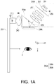
- FIG. 1A is a schematic view of a projection apparatus according to an embodiment of the disclosure.
- a projection apparatus 300A according to the embodiment of the disclosure includes an illumination system 350A and an image device 330A.
- the projection apparatus 300A is used in a head-mounted display.
- the image device 330A is, for example, a digital micro mirror device (DMD) that is configured to convert an illumination beam IL1 (a first illumination beam) from the illumination system 350A into an image beam ML.
- the image beam ML is transmitted to a target P such as human eyes through a lens module 340 and a waveguide system.
- the waveguide system includes a first waveguide device 310 and a second waveguide device 320.
- the lens module 340 and the waveguide system as shown in FIG. 1 are merely described with the embodiments, but not limited to the disclosure.
- the image beam ML leaves the projection apparatus 300A and converges at a stop ST.
- the stop ST is located outside the projection apparatus 300A, like in the waveguide system.
- the stop ST has the smallest cross-sectional area of the condensed image beam.
- the stop ST is round and is located on a plane formed by an X axis and a Y axis and moreover, the stop ST has the same size in the X axis direction as in the Y axis direction.
- the image beam ML after the image beam ML leaves the projection apparatus 300A, the smallest cross-sectional area of the condensed image beam ML is available on the stop ST. Therefore, the image beam ML converges at the stop ST after passing the projection apparatus 300A, and diverges after passing through the stop ST.
- the illumination system 350A is configured to provide the illumination beam IL1 for the image device 330A.
- the illumination system 350A includes an illumination light source 351 (a first illumination light source), a collimating lens set 353, a diffusion device 355, a light uniform device 357 and a prism module 359A.
- the illumination light source 351 is, for example, a laser diode.
- the illumination beam IL1 is transmitted to the image device 330A through the collimating lens set 353, the diffusion device 355, the light uniform device 357 and the prism module 359A.
- the diffusion device 355 is, for example, a diffuser with a diffuser angle of 60 degrees, but is not limited thereto. It is feasible to use a diffuser with different diffuser angles, depending on design.
- the diffusion device 355 may be made into a sheet having a thickness of less than 0.5 mm and is disposed between the collimating lens set 353 and the light uniform device 357.
- the light uniform device 357 is, for example, a single lens array, and the lens array may also be a fly-eye lens array.
- the light uniform device 357 may be formed by a plurality of lens arrays, but is not limited thereto.
- the prism module 359A includes a prism 352 (a first prism).
- the illumination beam IL 1 from the light uniform device 357 is transmitted to the image device 330A through the prism 352.
- the diffusion device 355 is disposed between the illumination light source 351 and the light uniform device 357. Therefore, the image beam ML has a uniform energy intensity (brightness) distribution on the stop.
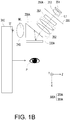
- FIG. 1B is a schematic view of a projection apparatus according to another embodiment of the disclosure.
- the projection apparatus 300A projects the image beam ML that is transmitted to the target P through the lens module 340 and the waveguide system.
- the waveguide system only has a first waveguide device 310.
- the image beam ML leaves the projection apparatus 300A and converges at the stop ST.
- the stop ST is located outside the projection apparatus 300A, like in a region of a light entrance surface of the first waveguide device 310.
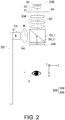
- FIG. 2 is a schematic view of a projection apparatus according to another embodiment of the disclosure.
- a projection apparatus 300B according to the embodiment is similar to the projection apparatus 300A in FIG. 1A , but the main difference between the projection apparatus 300A and the projection apparatus 300B lies in, for example, design methods of an illumination system 350B and an image device 330B.
- the image device 330B includes, for example, a liquid crystal on silicon (LCoS) display that is configured to convert the illumination beam IL1 from the illumination system 350B into the image beam ML.
- the image beam ML is transmitted to the target P through the waveguide system.
- the illumination system 350B is configured to provide the illumination beam IL1 for the image device 330B.
- the diffusion device 355 is disposed between the collimating lens set 353 and the light uniform device 357.
- a prism module 359B includes a first prism 352_1 and a second prism 352_2.
- a coating layer of a polarity or a film of a polarity between the first prism 352_1 and the second prism 352_2 forms a polarizing beam splitter (PBS).
- the partial illumination beam IL1 of a first polarity that comes from the light uniform device 357 is transmitted to the image device 330B through the first prism 352_1 and the second prism 352_2.
- the image device 330B converts the partial illumination beam IL1 of the first polarity into the partial illumination beam IL1 of a second polarity and reflects the partial illumination beam IL1 of the second polarity to the polarizing beam splitter.
- the polarizing beam splitter reflects the partial illumination beam IL1 of the second polarity to the lens module 340.
- the image beam ML leaves the projection apparatus 300B and converges at the stop ST.
- the stop is located outside the projection apparatus 300B, like in the waveguide system.
- the diffusion device 355 is disposed between the illumination light source 351 and the light uniform device 357. Therefore, the image beam ML has a uniform energy intensity distribution on the stop ST.
- FIG. 3 is a schematic view of a projection apparatus according to another embodiment of the disclosure.
- a projection apparatus 300C according to the embodiment is similar to the projection apparatus 300A in FIG. 1A , but the main difference between the projection apparatus 300C and the projection apparatus 300A lies in a design method of a prism module 359C.
- an image device 330C includes, for example, a digital micromirror device that is configured to convert the illumination beam IL1 from an illumination system 350C into the image beam ML.
- the image beam ML is transmitted to the target P through the waveguide system.
- the prism module 359C includes a first prism 359_1, a second prism 359_2 and a third prism 359_3.
- the first prism 359_1 has a curved surface that may further have a reflection layer R.
- the reflection layer R may be a reflective coating layer or formed by attaching a reflective sheet to the curved surface of the first prim 359_1.
- the curved surface is configured to reflect the illumination beam IL1 from the light uniform device 357, but is not limited thereto.
- the first prism 359_1 has a curved surface, but does not need the reflection layer R. With a full reflection characteristic, the curved surface of the first prism 359_1 may be configured to reflect the illumination beam IL1 from the light uniform device 357, but is not limited thereto.
- air gaps are available between the two prisms in FIG. 3 .
- a first gap is located between the first prism 359_1 and the second prism 359_2.
- a second gap is located between the second prism 359_2 and the third prism 359_3.
- the illumination beam IL1 from the light uniform device 357 is transmitted to the image device 330C through the first prism 359_1, the curved surface of the first prism 359_1, the first gap, the second prism 359_2, the second gap and the third prism 359_3 sequentially.
- first prism 359_1 is bonded to the second prism 359_2 with a transparent plastic material
- the second prism 359_2 may be bonded to the third prism 359_3.
- the transparent plastic material, the first prism 359_1, the second prism 359_2 and the third prism 359_3 have different refractive indexes.
- the illumination beam IL1 from the illumination light source 351 may converge at an aperture stop 358 within the illumination system 350C, so ghost images on an image screen may be reduced.
- the aperture stop 358 is, for example, located behind the diffusion device 355, but is not limited thereto. In another embodiment, the aperture stop 358 is, for example, located in front of the diffusion device 355, like between the collimating lens set 353 and the diffusion device 355, or between the diffusion device 355 and the light uniform device 357.
- the aperture stop 358 is a tangible object and may have a driving device (not shown). The driving device is configured to control the size of an aperture of the aperture stop 358.
- the aperture stop 358 may adjust the light amount of the illumination beam IL1 passing through the aperture of the aperture stop 358.
- the aperture of the aperture stop 358 may be of fixed size.
- the illumination beam ML leaves the projection apparatus 300C and converges at the stop ST that is located outside the projection apparatus 300C.
- the stop ST is, for example, located in the first waveguide device 310.
- the image device 330C includes a light valve.
- the light valve has an active surface S1 configured to receive all the first illumination beams IL1 from the illumination system 350C.
- An area of the active surface S1 receiving the first illumination beam IL1 is smaller than an area of a surface S2 of the third prism 359_3 facing the active surface S1 of the light valve. That is, S1 is greater than S2. Therefore, the active surface S1 of the light valve receiving the illumination beam IL1 from the third prism 359_3 has the largest effective irradiation range that is useful for making the most of the active surface S1 of the light valve.
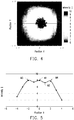
- FIG. 4 is a graph illustrating an energy intensity distribution of an image beam on a stop.
- the peak value M1 is the greatest among all the peak values and is closest to a center of the stop ST.
- the center of the stop ST is, for example, where an optical axis OA passes through the stop ST.
- the valley value M2 is the lowest intensity value between the peak value M1 and another peak value adjacent to the peak value M1.
- the another peak value may be a left peak value M3 or a right peak value M4 that is adjacent to the peak value M1. Therefore, the valley value M2 is selected from a valley value between the peak value M1 and the right peak value M4. In other embodiments, the valley value may be selected from the lowest intensity value between the peak value M1 and the left peak value M3.
- uniformity M of the energy intensity distribution of the image beam ML on the stop ST equals (M1 - M2) / (M1 + M2) x 100%, and M1 is greater than M2. In another embodiment, the uniformity M of the energy intensity distribution is less than 15%. In the embodiment, the uniformity M of the energy intensity distribution is less than 10%.
- the diffusion device 355 is disposed between the illumination light source 351 and the light uniform device 357. Therefore, the image beam ML has a uniform energy intensity distribution on the stop ST.
- the peak value M1 8
- the valley value M2 7.3
- the peak value M4 7.9
- M is less than 10%.
- the diffusion device 355 includes a diffuser.
- a diffuser angle of the diffuser may be circular symmetrical, monosymmetrical or asymmetrical. The disclosure is not limited to the type of diffuser.
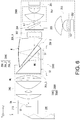
- FIG. 6 is a schematic view of a projection apparatus according to another embodiment of the disclosure.
- a projection apparatus 300D according to the embodiment is similar to the projection apparatus 300C in FIG. 3 , but the main difference between the projection apparatus 300D and the projection apparatus 300C lies in a design method of an illumination system 350D.
- the illumination system 350D further includes the second illumination light source 352 and a light combining device 354.
- the second illumination light source 352 is configured to provide the second illumination beam IL2.
- the light combining device 354 is, for example, a wedge prism configured to integrate a third illumination beam IL1' with the second illumination beam IL2 to form the first illumination beam IL1.
- the third illumination beam IL1' is, for example, red light
- the second illumination beam IL2 is, for example, green light and blue light, but the embodiment is not limited thereto.
- the first illumination beam IL1 is transmitted to the image device 330C through the diffusion device 355, the light uniform device 357 and the prism module 359C sequentially.
- the light combining device 354 is, for example, a dichroic mirror configured to integrate the third illumination beam IL1' with the second illumination beam IL2 to for the first illumination beam IL1.
- the illumination system includes the diffusion device disposed between the illumination beam and the light uniform device to allow the image beam to have a uniform energy intensity distribution on the stop.
- the term "the invention”, “the present invention” or the like does not necessarily limit the claim scope to a specific embodiment, and the reference to particularly preferred exemplary embodiments of the invention does not imply a limitation on the invention, and no such limitation is to be inferred.
- the invention is limited only by the scope of the appended claims.
- the abstract of the disclosure is provided to comply with the rules requiring an abstract, which will allow a searcher to quickly ascertain the subject matter of the technical disclosure of any patent issued from this disclosure. It is submitted with the understanding that it will not be used to interpret or limit the scope or meaning of the claims. Any advantages and benefits described may not apply to all embodiments of the invention.
Landscapes
- Physics & Mathematics (AREA)
- General Physics & Mathematics (AREA)
- Optics & Photonics (AREA)
- Projection Apparatus (AREA)
- Transforming Electric Information Into Light Information (AREA)
- Microscoopes, Condenser (AREA)
- Optical Elements Other Than Lenses (AREA)
Abstract
Description
- This application claims the priority of China application serial no.
201711383884.3, filed on December 20, 2017 - The disclosure relates to a projection apparatus and particularly relates to a projection apparatus for a head-mounted display.
- A near eye display (NED) and a head-mounted display (HMD) are the next generation of killer products that have enormous potential for development at present. The relevant application of a near eye display technique may be categorized into an augmented reality (AR) technique and a virtual reality (VR) technique currently. For the augmented reality technique, researchers are now committed to working on how to provide optimum image quality on the premise that the display is lightweight and thin. In the optical structure of augmented reality, after a projection apparatus emits an image beam that is to be displayed, whether an energy intensity distribution outside a stop is uniform influences picture uniformity perceived by the human eye, thereby influencing the visual quality for a user. Therefore, how to enable the user to have desirable visual quality for a pleasant user experience is now one of the significant issues.
- The information disclosed in this Background section is only for enhancement of understanding of the background of the described technology and therefore it may contain information that does not form the prior art that is already known to a person of ordinary skill in the art. Further, the information disclosed in the Background section does not mean that one or more problems to be resolved by one or more embodiments of the invention were acknowledged by a person of ordinary skill in the art.
- The disclosure provides a projection apparatus whose image beam has a uniform energy intensity distribution on a stop.
- Other purposes and advantages of the disclosure may be further understood based on the technical features disclosed by the disclosure.
- The object is solved by the features of the independent claims. Preferred embodiments are given in the dependent claims.
- To achieve one, some or all of the purposes above or other purposes, an embodiment of the disclosure provides a projection apparatus. The projection apparatus includes an image device and an illumination system.
- The image device is configured to convert a first illumination beam into an image beam. The illumination system includes a first illumination light source, a diffusion device and a light uniform device.
- The first illumination light source provides a first illumination beam that is transmitted to the image device through the diffusion device and the light uniform device sequentially.
- The image beam leaves the projection apparatus and converges at a stop that is located outside the projection apparatus. The diffusion device is configured to allow the image beam to have an energy intensity distribution, where a peak value M1 and a valley value M2 are included, a uniformity M equals (M1 - M2) / (M1 + M2) × 100%, and the peak value M1 is greater than the valley value M2, in a reference direction of the stop.
- Preferably, the peak value M1 is the greatest value among the peak values and is closest to a center of the stop, and the valley value M2 is located between the peak value M1 and another peak value adjacent to the valley value M2.
- Preferably, the illumination system further comprises a collimating lens set and a prism module.
- Preferably, the first illumination beam is transmitted to the image device through the collimating lens set, the diffusion device, the light uniform device and the prism module sequentially.
- Preferably, the light uniform device is a lens array.
- Preferably, the illumination system further comprises an aperture stop, the aperture stop is disposed between the collimating lens set and the light uniform device.
- Preferably, the prism module comprises a first prism, and the first illumination beam from the light uniform device is transmitted to the image device through the first prism.
- Preferably, the prism module comprises a first prism, a second prism and a third prism, and the first illumination beam from the light uniform device is transmitted to the image device through the first prism, the second prism and the third prism.
- Preferably, a first gap is located between the first prism and the second prism, a second gap is located between the second prism and the third prism, and the first illumination beam from the light uniform device is transmitted to the image device through the first gap and the second gap.
- Preferably, the first prism has a curved surface that is configured to reflect the first illumination beam from the light uniform device.
- Preferably, the first prism has a reflection layer that is configured to reflect the first illumination beam from the light uniform device.
- Preferably, the image device comprises a light valve having an active surface that is configured to receive the first illumination beam from the illumination system, and an area of the active surface of the light valve receiving the first illumination beam is smaller than an area of a surface of the third prism facing the active surface of the light valve.
- Preferably, the illumination system further comprises a second illumination light source that is configured to provide a second illumination beam.
- Preferably, the illumination system further comprises a light combining device that integrates the second illumination beam to form the first illumination beam, wherein the first illumination beam is transmitted to the image device through the diffusion device and the light uniform device sequentially.
- Preferably, the image beam has the uniformity M of less than 15% on the stop.
- Preferably, the image beam has the uniformity M of less than 10% on the stop.
- Other objectives, features and advantages of the invention will be further understood from the further technological features disclosed by the embodiments of the invention wherein there are shown and described preferred embodiments of this invention, simply by way of illustration of modes best suited to carry out the invention.
- The accompanying drawings are included to provide a further understanding of the disclosure, and are incorporated in and constitute a part of this specification. The drawings illustrate embodiments of the disclosure and, together with the description, serve to explain the principles of the disclosure.
-
FIG. 1A is a schematic view of a projection apparatus according to an embodiment of the disclosure. -
FIG. 1B is a schematic view of a projection apparatus according to another embodiment of the disclosure. -
FIG. 2 is a schematic view of a projection apparatus according to another embodiment of the disclosure. -
FIG. 3 is a schematic view of a projection apparatus according to another embodiment of the disclosure. -
FIG. 4 is a graph illustrating an energy intensity distribution of an image beam outside a stop. -
FIG. 5 is a curve illustrating the energy intensity distribution of an image beam in an X direction where Y = 0. -
FIG. 6 is a schematic view of a projection apparatus according to another embodiment of the disclosure. - In the following detailed description of the preferred embodiments, reference is made to the accompanying drawings which form a part hereof, and in which are shown by way of illustration specific embodiments in which the invention may be practiced. In this regard, directional terminology, such as "top," "bottom," "front," "back," etc., is used with reference to the orientation of the Figure(s) being described. The components of the invention can be positioned in a number of different orientations. As such, the directional terminology is used for purposes of illustration and is in no way limiting. On the other hand, the drawings are only schematic and the sizes of components may be exaggerated for clarity. It is to be understood that other embodiments may be utilized and structural changes may be made without departing from the scope of the invention. Also, it is to be understood that the phraseology and terminology used herein are for the purpose of description and should not be regarded as limiting. The use of "including," "comprising," or "having" and variations thereof herein is meant to encompass the items listed thereafter and equivalents thereof as well as additional items. Unless limited otherwise, the terms "connected," "coupled," and "mounted" and variations thereof herein are used broadly and encompass direct and indirect connections, couplings, and mountings. Similarly, the terms "facing," "faces" and variations thereof herein are used broadly and encompass direct and indirect facing, and "adjacent to" and variations thereof herein are used broadly and encompass directly and indirectly "adjacent to". Therefore, the description of "A" component facing "B" component herein may contain the situations that "A" component directly faces "B" component or one or more additional components are between "A" component and "B" component. Also, the description of "A" component "adjacent to" "B" component herein may contain the situations that "A" component is directly "adjacent to" "B" component or one or more additional components are between "A" component and "B" component. Accordingly, the drawings and descriptions will be regarded as illustrative in nature and not as restrictive.
-
FIG. 1A is a schematic view of a projection apparatus according to an embodiment of the disclosure. Referring toFIG. 1A , aprojection apparatus 300A according to the embodiment of the disclosure includes anillumination system 350A and animage device 330A. Theprojection apparatus 300A is used in a head-mounted display. In the embodiment, theimage device 330A is, for example, a digital micro mirror device (DMD) that is configured to convert an illumination beam IL1 (a first illumination beam) from theillumination system 350A into an image beam ML. The image beam ML is transmitted to a target P such as human eyes through alens module 340 and a waveguide system. The waveguide system includes afirst waveguide device 310 and asecond waveguide device 320. Thelens module 340 and the waveguide system as shown inFIG. 1 are merely described with the embodiments, but not limited to the disclosure. - In the embodiment, the image beam ML leaves the
projection apparatus 300A and converges at a stop ST. The stop ST is located outside theprojection apparatus 300A, like in the waveguide system. The stop ST has the smallest cross-sectional area of the condensed image beam. For example, in the embodiment, the stop ST is round and is located on a plane formed by an X axis and a Y axis and moreover, the stop ST has the same size in the X axis direction as in the Y axis direction. In the embodiment, after the image beam ML leaves theprojection apparatus 300A, the smallest cross-sectional area of the condensed image beam ML is available on the stop ST. Therefore, the image beam ML converges at the stop ST after passing theprojection apparatus 300A, and diverges after passing through the stop ST. - In the embodiment, the
illumination system 350A is configured to provide the illumination beam IL1 for theimage device 330A. Theillumination system 350A includes an illumination light source 351 (a first illumination light source), a collimating lens set 353, adiffusion device 355, a lightuniform device 357 and aprism module 359A. Theillumination light source 351, such as a light emitting diode (LED), provides the illumination beam IL1. In other embodiments, theillumination light source 351 is, for example, a laser diode. The illumination beam IL1 is transmitted to theimage device 330A through the collimating lens set 353, thediffusion device 355, the lightuniform device 357 and theprism module 359A. In the embodiment, thediffusion device 355 is, for example, a diffuser with a diffuser angle of 60 degrees, but is not limited thereto. It is feasible to use a diffuser with different diffuser angles, depending on design. Thediffusion device 355 may be made into a sheet having a thickness of less than 0.5 mm and is disposed between the collimating lens set 353 and the lightuniform device 357. The lightuniform device 357 is, for example, a single lens array, and the lens array may also be a fly-eye lens array. In the embodiment, the lightuniform device 357 may be formed by a plurality of lens arrays, but is not limited thereto. In the embodiment, theprism module 359A includes a prism 352 (a first prism). Theillumination beam IL 1 from the lightuniform device 357 is transmitted to theimage device 330A through theprism 352. In the embodiment, thediffusion device 355 is disposed between theillumination light source 351 and the lightuniform device 357. Therefore, the image beam ML has a uniform energy intensity (brightness) distribution on the stop. -
FIG. 1B is a schematic view of a projection apparatus according to another embodiment of the disclosure. Referring toFIGs. 1A and1B , the main differences are that theprojection apparatus 300A projects the image beam ML that is transmitted to the target P through thelens module 340 and the waveguide system. The waveguide system only has afirst waveguide device 310. In the embodiment, the image beam ML leaves theprojection apparatus 300A and converges at the stop ST. The stop ST is located outside theprojection apparatus 300A, like in a region of a light entrance surface of thefirst waveguide device 310. -
FIG. 2 is a schematic view of a projection apparatus according to another embodiment of the disclosure. Referring toFIGs. 1A and2 , aprojection apparatus 300B according to the embodiment is similar to theprojection apparatus 300A inFIG. 1A , but the main difference between theprojection apparatus 300A and theprojection apparatus 300B lies in, for example, design methods of anillumination system 350B and animage device 330B. - Specifically, in the embodiment, the
image device 330B includes, for example, a liquid crystal on silicon (LCoS) display that is configured to convert the illumination beam IL1 from theillumination system 350B into the image beam ML. The image beam ML is transmitted to the target P through the waveguide system. In the embodiment, theillumination system 350B is configured to provide the illumination beam IL1 for theimage device 330B. Thediffusion device 355 is disposed between the collimating lens set 353 and the lightuniform device 357. In the embodiment, aprism module 359B includes a first prism 352_1 and a second prism 352_2. A coating layer of a polarity or a film of a polarity between the first prism 352_1 and the second prism 352_2 forms a polarizing beam splitter (PBS). The partial illumination beam IL1 of a first polarity that comes from the lightuniform device 357 is transmitted to theimage device 330B through the first prism 352_1 and the second prism 352_2. Theimage device 330B converts the partial illumination beam IL1 of the first polarity into the partial illumination beam IL1 of a second polarity and reflects the partial illumination beam IL1 of the second polarity to the polarizing beam splitter. The polarizing beam splitter reflects the partial illumination beam IL1 of the second polarity to thelens module 340. - In the embodiment, the image beam ML leaves the
projection apparatus 300B and converges at the stop ST. The stop is located outside theprojection apparatus 300B, like in the waveguide system. In the embodiment, thediffusion device 355 is disposed between theillumination light source 351 and the lightuniform device 357. Therefore, the image beam ML has a uniform energy intensity distribution on the stop ST. -
FIG. 3 is a schematic view of a projection apparatus according to another embodiment of the disclosure. Referring toFIGs. 1A and3 , a projection apparatus 300C according to the embodiment is similar to theprojection apparatus 300A inFIG. 1A , but the main difference between the projection apparatus 300C and theprojection apparatus 300A lies in a design method of aprism module 359C. - Specifically, in the embodiment, an
image device 330C includes, for example, a digital micromirror device that is configured to convert the illumination beam IL1 from anillumination system 350C into the image beam ML. The image beam ML is transmitted to the target P through the waveguide system. In the embodiment, theprism module 359C includes a first prism 359_1, a second prism 359_2 and a third prism 359_3. In the embodiment, the first prism 359_1 has a curved surface that may further have a reflection layer R. The reflection layer R may be a reflective coating layer or formed by attaching a reflective sheet to the curved surface of the first prim 359_1. The curved surface is configured to reflect the illumination beam IL1 from the lightuniform device 357, but is not limited thereto. In other embodiments, the first prism 359_1 has a curved surface, but does not need the reflection layer R. With a full reflection characteristic, the curved surface of the first prism 359_1 may be configured to reflect the illumination beam IL1 from the lightuniform device 357, but is not limited thereto. - In the embodiment, air gaps are available between the two prisms in
FIG. 3 . For example, a first gap is located between the first prism 359_1 and the second prism 359_2. A second gap is located between the second prism 359_2 and the third prism 359_3. The illumination beam IL1 from the lightuniform device 357 is transmitted to theimage device 330C through the first prism 359_1, the curved surface of the first prism 359_1, the first gap, the second prism 359_2, the second gap and the third prism 359_3 sequentially. In another embodiment, the first prism 359_1 is bonded to the second prism 359_2 with a transparent plastic material, and the second prism 359_2 may be bonded to the third prism 359_3. The transparent plastic material, the first prism 359_1, the second prism 359_2 and the third prism 359_3 have different refractive indexes. - In addition, in the embodiment, the illumination beam IL1 from the
illumination light source 351 may converge at anaperture stop 358 within theillumination system 350C, so ghost images on an image screen may be reduced. Theaperture stop 358 is, for example, located behind thediffusion device 355, but is not limited thereto. In another embodiment, theaperture stop 358 is, for example, located in front of thediffusion device 355, like between the collimating lens set 353 and thediffusion device 355, or between thediffusion device 355 and the lightuniform device 357. Theaperture stop 358 is a tangible object and may have a driving device (not shown). The driving device is configured to control the size of an aperture of theaperture stop 358. Therefore, theaperture stop 358 may adjust the light amount of the illumination beam IL1 passing through the aperture of theaperture stop 358. In an embodiment, the aperture of theaperture stop 358 may be of fixed size. In the embodiment, the illumination beam ML leaves the projection apparatus 300C and converges at the stop ST that is located outside the projection apparatus 300C. In the embodiment, the stop ST is, for example, located in thefirst waveguide device 310. - In the embodiment, the
image device 330C includes a light valve. The light valve has an active surface S1 configured to receive all the first illumination beams IL1 from theillumination system 350C. An area of the active surface S1 receiving the first illumination beam IL1 is smaller than an area of a surface S2 of the third prism 359_3 facing the active surface S1 of the light valve. That is, S1 is greater than S2. Therefore, the active surface S1 of the light valve receiving the illumination beam IL1 from the third prism 359_3 has the largest effective irradiation range that is useful for making the most of the active surface S1 of the light valve. -
FIG. 4 is a graph illustrating an energy intensity distribution of an image beam on a stop.FIG. 5 is a curve illustrating an energy intensity distribution of an image beam in an X direction where Y = 0. In the embodiment, the energy intensity distribution of the image beam ML in a position of the X direction (reference direction) of the stop ST, where Y = 0, includes many peak values and valley values. The peak value M1 is the greatest among all the peak values and is closest to a center of the stop ST. In the embodiment, the center of the stop ST is, for example, where an optical axis OA passes through the stop ST. The valley value M2 is the lowest intensity value between the peak value M1 and another peak value adjacent to the peak value M1. In the embodiment, the another peak value may be a left peak value M3 or a right peak value M4 that is adjacent to the peak value M1. Therefore, the valley value M2 is selected from a valley value between the peak value M1 and the right peak value M4. In other embodiments, the valley value may be selected from the lowest intensity value between the peak value M1 and the left peak value M3. In the embodiment, uniformity M of the energy intensity distribution of the image beam ML on the stop ST equals (M1 - M2) / (M1 + M2) x 100%, and M1 is greater than M2. In another embodiment, the uniformity M of the energy intensity distribution is less than 15%. In the embodiment, the uniformity M of the energy intensity distribution is less than 10%. A smaller M value indicates that the image beam ML has a more uniform energy intensity distribution on the stop ST. Therefore, in the embodiment, thediffusion device 355 is disposed between theillumination light source 351 and the lightuniform device 357. Therefore, the image beam ML has a uniform energy intensity distribution on the stop ST. For example, inFIG. 5 , the peak value M1 = 8, the valley value M2 = 7.3, the peak value M4 = 7.9, M = (8 - 7.3) / (8 + 7.3) × 100% = 4.5%, and M is less than 10%. - The
diffusion device 355 includes a diffuser. A diffuser angle of the diffuser may be circular symmetrical, monosymmetrical or asymmetrical. The disclosure is not limited to the type of diffuser. -
FIG. 6 is a schematic view of a projection apparatus according to another embodiment of the disclosure. Referring toFIGs. 3 and6 , aprojection apparatus 300D according to the embodiment is similar to the projection apparatus 300C inFIG. 3 , but the main difference between theprojection apparatus 300D and the projection apparatus 300C lies in a design method of anillumination system 350D. Specifically, in the embodiment, theillumination system 350D further includes the secondillumination light source 352 and alight combining device 354. The secondillumination light source 352 is configured to provide the second illumination beam IL2. Thelight combining device 354 is, for example, a wedge prism configured to integrate a third illumination beam IL1' with the second illumination beam IL2 to form the first illumination beam IL1. The third illumination beam IL1' is, for example, red light, and the second illumination beam IL2 is, for example, green light and blue light, but the embodiment is not limited thereto. The first illumination beam IL1 is transmitted to theimage device 330C through thediffusion device 355, the lightuniform device 357 and theprism module 359C sequentially. In other embodiments, thelight combining device 354 is, for example, a dichroic mirror configured to integrate the third illumination beam IL1' with the second illumination beam IL2 to for the first illumination beam IL1. - In view of the foregoing, in the exemplary embodiments of the disclosure, the illumination system includes the diffusion device disposed between the illumination beam and the light uniform device to allow the image beam to have a uniform energy intensity distribution on the stop.
- The foregoing description of the preferred embodiments of the invention has been presented for purposes of illustration and description. It is not intended to be exhaustive or to limit the invention to the precise form or to exemplary embodiments disclosed. Accordingly, the foregoing description should be regarded as illustrative rather than restrictive. Obviously, many modifications and variations will be apparent to practitioners skilled in this art. The embodiments are chosen and described in order to best explain the principles of the invention and its best mode practical application, thereby to enable persons skilled in the art to understand the invention for various embodiments and with various modifications as are suited to the particular use or implementation contemplated. It is intended that the scope of the invention be defined by the claims appended hereto and their equivalents in which all terms are meant in their broadest reasonable sense unless otherwise indicated. Therefore, the term "the invention", "the present invention" or the like does not necessarily limit the claim scope to a specific embodiment, and the reference to particularly preferred exemplary embodiments of the invention does not imply a limitation on the invention, and no such limitation is to be inferred. The invention is limited only by the scope of the appended claims. The abstract of the disclosure is provided to comply with the rules requiring an abstract, which will allow a searcher to quickly ascertain the subject matter of the technical disclosure of any patent issued from this disclosure. It is submitted with the understanding that it will not be used to interpret or limit the scope or meaning of the claims. Any advantages and benefits described may not apply to all embodiments of the invention. It should be appreciated that variations may be made in the embodiments described by persons skilled in the art without departing from the scope of the present invention as defined by the following claims. Moreover, no element and component in the present disclosure is intended to be dedicated to the public regardless of whether the element or component is explicitly recited in the following claims.
Claims (15)
- A projection apparatus, comprising:an image device, configured to convert a first illumination beam into an image beam; andan illumination system comprising:a first illumination light source;a diffusion device; anda light uniform device, wherein the first illumination light source provides the first illumination beam, the first illumination beam is transmitted to the image device through the diffusion device and the light uniform device sequentially,wherein the image beam leaves the projection apparatus and converges at a stop, the stop is located outside the projection apparatus,wherein the diffusion device is configured to allow the image beam to have an energy intensity distribution, where a peak value M1 and a valley value M2 are included, a uniformity M equals (M1 - M2) / (M1 + M2) × 100%, and the peak value M1 is greater than the valley value M2, in a reference direction of the stop.
- The projection apparatus of claim 1, wherein the peak value M1 is the greatest value among the peak values and is closest to a center of the stop, and the valley value M2 is located between the peak value M1 and another peak value adjacent to the valley value M2.
- The projection apparatus of claim 1 or 2, wherein the illumination system further comprises a collimating lens set and a prism module, the first illumination beam is transmitted to the image device through the collimating lens set, the diffusion device, the light uniform device and the prism module sequentially.
- The projection apparatus of any one of the preceding claims, wherein the light uniform device is a lens array.
- The projection apparatus of claim 3 or 4, wherein the illumination system further comprises an aperture stop, the aperture stop is disposed between the collimating lens set and the light uniform device.
- The projection apparatus of claim 3, 4 or 5, wherein the prism module comprises a first prism, and the first illumination beam from the light uniform device is transmitted to the image device through the first prism.
- The projection apparatus of claim 3, 4, 5 or 6, wherein the prism module comprises a first prism, a second prism and a third prism, and the first illumination beam from the light uniform device is transmitted to the image device through the first prism, the second prism and the third prism.
- The projection apparatus of claim 7, wherein a first gap is located between the first prism and the second prism, a second gap is located between the second prism and the third prism, and the first illumination beam from the light uniform device is transmitted to the image device through the first gap and the second gap.
- The projection apparatus of claim 7 or 8, wherein the first prism has a curved surface that is configured to reflect the first illumination beam from the light uniform device.
- The projection apparatus of claim 7, 8 or 9, wherein the first prism has a reflection layer that is configured to reflect the first illumination beam from the light uniform device.
- The projection apparatus of claim 7, 8, 9 or 10, wherein the image device comprises a light valve having an active surface that is configured to receive the first illumination beam from the illumination system, and an area of the active surface of the light valve receiving the first illumination beam is smaller than an area of a surface of the third prism facing the active surface of the light valve.
- The projection apparatus according to any one of the preceding claims, wherein the illumination system further comprises a second illumination light source that is configured to provide a second illumination beam.
- The projection apparatus of claim 12, wherein the illumination system further comprises a light combining device that integrates the second illumination beam to form the first illumination beam, wherein the first illumination beam is transmitted to the image device through the diffusion device and the light uniform device sequentially.
- The projection apparatus according to any one of the preceding claims, wherein the image beam has the uniformity M of less than 15% on the stop.
- The projection apparatus according to any one of the preceding claims, wherein the image beam has the uniformity M of less than 10% on the stop.
Applications Claiming Priority (1)
| Application Number | Priority Date | Filing Date | Title |
|---|---|---|---|
| CN201711383884.3A CN109946907A (en) | 2017-12-20 | 2017-12-20 | Projection device |
Publications (2)
| Publication Number | Publication Date |
|---|---|
| EP3502766A1 true EP3502766A1 (en) | 2019-06-26 |
| EP3502766B1 EP3502766B1 (en) | 2022-03-02 |
Family
ID=64665210
Family Applications (1)
| Application Number | Title | Priority Date | Filing Date |
|---|---|---|---|
| EP18212104.6A Active EP3502766B1 (en) | 2017-12-20 | 2018-12-12 | Projection apparatus |
Country Status (5)
| Country | Link |
|---|---|
| US (1) | US10809609B2 (en) |
| EP (1) | EP3502766B1 (en) |
| JP (1) | JP7141323B2 (en) |
| CN (1) | CN109946907A (en) |
| TW (1) | TWI694297B (en) |
Cited By (3)
| Publication number | Priority date | Publication date | Assignee | Title |
|---|---|---|---|---|
| US20190369399A1 (en) * | 2018-05-31 | 2019-12-05 | Coretronic Corporation | Head-mounted display device |
| EP3761103A1 (en) * | 2019-07-05 | 2021-01-06 | Coretronic Corporation | Head-mounted display device |
| WO2022182519A1 (en) * | 2021-02-28 | 2022-09-01 | Snap Inc. | Projector with field lens |
Families Citing this family (5)
| Publication number | Priority date | Publication date | Assignee | Title |
|---|---|---|---|---|
| CN111819843A (en) * | 2018-03-09 | 2020-10-23 | 马克斯-普朗克科学促进学会 | system for displaying information to users |
| EP3988837B1 (en) | 2019-06-19 | 2024-06-12 | Koito Manufacturing Co., Ltd. | Vehicular air curtain system |
| CN112925097A (en) * | 2019-12-05 | 2021-06-08 | 中强光电股份有限公司 | Projection equipment and wearable display device |
| KR102887721B1 (en) | 2020-07-17 | 2025-11-17 | 삼성전자주식회사 | Augmented reality display apparatus |
| WO2025019431A1 (en) * | 2023-07-14 | 2025-01-23 | Google Llc | Head-mounted display with reduced ghost images |
Citations (4)
| Publication number | Priority date | Publication date | Assignee | Title |
|---|---|---|---|---|
| JP2003029203A (en) * | 2001-07-13 | 2003-01-29 | Victor Co Of Japan Ltd | Projection type display device |
| US6577429B1 (en) * | 2002-01-15 | 2003-06-10 | Eastman Kodak Company | Laser projection display system |
| US20130250431A1 (en) * | 2012-03-21 | 2013-09-26 | Steve Robbins | Two-dimensional exit-pupil expansion |
| US20150138446A1 (en) * | 2013-11-20 | 2015-05-21 | Texas Instruments Incorporated | Compact Optical Projection Apparatus |
Family Cites Families (56)
| Publication number | Priority date | Publication date | Assignee | Title |
|---|---|---|---|---|
| JPS61931A (en) | 1984-06-12 | 1986-01-06 | Matsushita Electric Ind Co Ltd | Optical recording and reproducing device |
| FR2647556B1 (en) | 1989-05-23 | 1993-10-29 | Thomson Csf | OPTICAL DEVICE FOR INTRODUCING A COLLIMATED IMAGE INTO THE VISUAL FIELD OF AN OBSERVER AND HELMET COMPRISING AT LEAST ONE SUCH DEVICE |
| US6563626B1 (en) | 1999-02-25 | 2003-05-13 | Brother Kogyo Kabushiki Kaisha | Display device |
| JP2001272722A (en) | 2000-03-24 | 2001-10-05 | Nikon Corp | Projection display device |
| PL209571B1 (en) | 2000-06-05 | 2011-09-30 | Lumus Ltd | Substrate-guided optical beam expander |
| US6824275B2 (en) * | 2001-12-31 | 2004-11-30 | Texas Instruments Incorporated | Folded projection lens |
| IL148804A (en) | 2002-03-21 | 2007-02-11 | Yaacov Amitai | Optical device |
| US6646806B1 (en) | 2002-05-17 | 2003-11-11 | Infocus Corporation | Polarized light source system with dual optical paths |
| EP1731943B1 (en) | 2004-03-29 | 2019-02-13 | Sony Corporation | Optical device and virtual image display device |
| JP4393974B2 (en) | 2004-11-29 | 2010-01-06 | 京セラ株式会社 | Illumination optical device and projection display device |
| KR101210804B1 (en) | 2005-03-22 | 2012-12-10 | 혼하이 프리시젼 인더스트리 컴퍼니 리미티드 | optical system using total internal reflection images |
| JP4904741B2 (en) * | 2005-08-09 | 2012-03-28 | 株式会社日立製作所 | Projection-type image display device and shading method |
| US9081178B2 (en) | 2005-09-07 | 2015-07-14 | Bae Systems Plc | Projection display for displaying an image to a viewer |
| EP2128682A3 (en) | 2005-09-07 | 2011-11-30 | BAE Systems PLC | A projection display |
| TWI337290B (en) | 2007-04-09 | 2011-02-11 | Young Optics Inc | Fixing mechanism for fixing a light valve and a thermal module of an optical engine |
| US8643948B2 (en) | 2007-04-22 | 2014-02-04 | Lumus Ltd. | Collimating optical device and system |
| JP4475302B2 (en) * | 2007-08-07 | 2010-06-09 | セイコーエプソン株式会社 | Projector and projection device |
| WO2010014164A1 (en) | 2008-07-31 | 2010-02-04 | Corning Incorporated | Active spot array lithographic projector system with regulated spots |
| US9366867B2 (en) | 2014-07-08 | 2016-06-14 | Osterhout Group, Inc. | Optical systems for see-through displays |
| JP5402293B2 (en) | 2009-06-22 | 2014-01-29 | ソニー株式会社 | Head-mounted display and image display method in head-mounted display |
| WO2011024291A1 (en) | 2009-08-28 | 2011-03-03 | 株式会社島津製作所 | Display device |
| US11320571B2 (en) | 2012-11-16 | 2022-05-03 | Rockwell Collins, Inc. | Transparent waveguide display providing upper and lower fields of view with uniform light extraction |
| JP5316510B2 (en) | 2010-10-26 | 2013-10-16 | 株式会社Jvcケンウッド | Projection display |
| JP5780129B2 (en) | 2011-11-22 | 2015-09-16 | ソニー株式会社 | Light beam expansion device, image display device, and optical device |
| CN102402005B (en) | 2011-12-06 | 2015-11-25 | 北京理工大学 | Bifocal-surface monocular stereo helmet-mounted display device with free-form surfaces |
| CN102789122A (en) * | 2012-07-17 | 2012-11-21 | 利达光电股份有限公司 | DLP (digital light processing) projection optical system based on LED (light-emitting diode) light source |
| JP5920095B2 (en) | 2012-07-31 | 2016-05-18 | 株式会社Jvcケンウッド | Image display device |
| CN102928981B (en) | 2012-11-14 | 2016-08-03 | 中航华东光电有限公司 | Optical system of holographic optical waveguide helmet display |
| US9933684B2 (en) | 2012-11-16 | 2018-04-03 | Rockwell Collins, Inc. | Transparent waveguide display providing upper and lower fields of view having a specific light output aperture configuration |
| FR2999301B1 (en) | 2012-12-12 | 2015-01-09 | Thales Sa | OPTICAL GUIDE OF COLLIMATE IMAGES WITH OPTICAL BEAM DEDOLDER AND OPTICAL DEVICE THEREFOR |
| US8937771B2 (en) | 2012-12-12 | 2015-01-20 | Microsoft Corporation | Three piece prism eye-piece |
| WO2014109115A1 (en) | 2013-01-10 | 2014-07-17 | ソニー株式会社 | Image display device, image generating device, and transparent spatial light modulating device |
| US8913865B1 (en) | 2013-06-27 | 2014-12-16 | Microsoft Corporation | Waveguide including light turning gaps |
| TWI484219B (en) | 2013-08-30 | 2015-05-11 | Univ Nat Chiao Tung | Head mounted display device |
| TWI504938B (en) | 2013-11-21 | 2015-10-21 | Univ Nat Chiao Tung | Illumination system and projection apparatus |
| JP6200791B2 (en) * | 2013-12-04 | 2017-09-20 | 株式会社日立エルジーデータストレージ | Optical unit, projection display device, and imaging device |
| JP2015148782A (en) | 2014-02-10 | 2015-08-20 | ソニー株式会社 | Image display device and display device |
| FR3020880B1 (en) | 2014-05-09 | 2016-05-27 | Thales Sa | VISUAL HEAD COMPRISING AN OPTICAL MIXER WITH EXPANSION OF PUPIL PILOTABLE |
| JP2016033867A (en) | 2014-07-31 | 2016-03-10 | ソニー株式会社 | Optical member, illumination unit, wearable display, and image display apparatus |
| AU2016258618B2 (en) | 2015-05-04 | 2021-05-06 | Magic Leap, Inc. | Separated pupil optical systems for virtual and augmented reality and methods for displaying images using same |
| JP6624199B2 (en) | 2015-06-30 | 2019-12-25 | コニカミノルタ株式会社 | Illumination optical system and projector |
| CN105093499B (en) * | 2015-07-06 | 2017-07-07 | 厦门颉轩光电有限公司 | A kind of imaging lens group |
| WO2017040530A1 (en) * | 2015-08-31 | 2017-03-09 | Reald Inc. | High dynamic range projection with multiple numerical aperture illumination |
| CN105182456A (en) * | 2015-09-11 | 2015-12-23 | 成都迅达光电有限公司 | Prism and projector |
| DE102015122055B4 (en) | 2015-12-17 | 2018-08-30 | Carl Zeiss Ag | Optical system and method for transmitting a source image |
| JP6641974B2 (en) | 2015-12-18 | 2020-02-05 | セイコーエプソン株式会社 | Virtual image display |
| CN107290816B (en) | 2016-03-30 | 2020-04-24 | 中强光电股份有限公司 | Optical waveguide element and head-mounted display device having the same |
| US10025093B2 (en) | 2016-04-13 | 2018-07-17 | Microsoft Technology Licensing, Llc | Waveguide-based displays with exit pupil expander |
| US10659669B2 (en) | 2016-04-18 | 2020-05-19 | Sony Corporation | Projection display unit |
| CN106125265B (en) * | 2016-08-17 | 2019-04-09 | 海信集团有限公司 | projection imaging system |
| CN106054359B (en) * | 2016-08-17 | 2018-11-23 | 海信集团有限公司 | An ultra-short-focus projection lens and laser projection equipment |
| US10466479B2 (en) | 2016-10-07 | 2019-11-05 | Coretronic Corporation | Head-mounted display apparatus and optical system |
| CN106647128A (en) | 2016-12-29 | 2017-05-10 | 海信集团有限公司 | Optical engine and laser protection equipment |
| CN108333752B (en) | 2017-01-19 | 2020-12-29 | 中强光电股份有限公司 | Optical system and head-mounted display device |
| US10409066B2 (en) | 2017-01-19 | 2019-09-10 | Coretronic Corporation | Head-mounted display device with waveguide elements |
| CN108873326A (en) | 2017-05-16 | 2018-11-23 | 中强光电股份有限公司 | Head-mounted display device |
-
2017
- 2017-12-20 CN CN201711383884.3A patent/CN109946907A/en active Pending
-
2018
- 2018-08-21 TW TW107129126A patent/TWI694297B/en active
- 2018-12-11 US US16/215,660 patent/US10809609B2/en active Active
- 2018-12-12 EP EP18212104.6A patent/EP3502766B1/en active Active
- 2018-12-12 JP JP2018232230A patent/JP7141323B2/en active Active
Patent Citations (4)
| Publication number | Priority date | Publication date | Assignee | Title |
|---|---|---|---|---|
| JP2003029203A (en) * | 2001-07-13 | 2003-01-29 | Victor Co Of Japan Ltd | Projection type display device |
| US6577429B1 (en) * | 2002-01-15 | 2003-06-10 | Eastman Kodak Company | Laser projection display system |
| US20130250431A1 (en) * | 2012-03-21 | 2013-09-26 | Steve Robbins | Two-dimensional exit-pupil expansion |
| US20150138446A1 (en) * | 2013-11-20 | 2015-05-21 | Texas Instruments Incorporated | Compact Optical Projection Apparatus |
Cited By (7)
| Publication number | Priority date | Publication date | Assignee | Title |
|---|---|---|---|---|
| US20190369399A1 (en) * | 2018-05-31 | 2019-12-05 | Coretronic Corporation | Head-mounted display device |
| EP3761103A1 (en) * | 2019-07-05 | 2021-01-06 | Coretronic Corporation | Head-mounted display device |
| WO2022182519A1 (en) * | 2021-02-28 | 2022-09-01 | Snap Inc. | Projector with field lens |
| US11792371B2 (en) | 2021-02-28 | 2023-10-17 | Snap Inc. | Projector with field lens |
| EP4298473A1 (en) * | 2021-02-28 | 2024-01-03 | Snap, Inc. | Projector with field lens |
| US12114103B2 (en) | 2021-02-28 | 2024-10-08 | Snap Inc. | Projector with field lens |
| EP4647816A3 (en) * | 2021-02-28 | 2026-01-07 | Snap Inc. | Projector with field lens |
Also Published As
| Publication number | Publication date |
|---|---|
| CN109946907A (en) | 2019-06-28 |
| JP7141323B2 (en) | 2022-09-22 |
| EP3502766B1 (en) | 2022-03-02 |
| TW201928496A (en) | 2019-07-16 |
| JP2019113842A (en) | 2019-07-11 |
| TWI694297B (en) | 2020-05-21 |
| US10809609B2 (en) | 2020-10-20 |
| US20190187547A1 (en) | 2019-06-20 |
Similar Documents
| Publication | Publication Date | Title |
|---|---|---|
| US10809609B2 (en) | Projection apparatus | |
| US11867906B2 (en) | Wearable AR system and AR display device | |
| KR102041907B1 (en) | Head-mounted display device | |
| KR102115899B1 (en) | Head-mounted display device | |
| US10754162B2 (en) | Projection apparatus and head-mounted display device | |
| CN105259605B (en) | Guide structure and optical device | |
| US20190369399A1 (en) | Head-mounted display device | |
| JP7183611B2 (en) | virtual image display | |
| WO2019042133A1 (en) | Near-eye display system and near-eye display device | |
| US20220019081A1 (en) | Waveguide and head-mounted display device | |
| EP3599489A1 (en) | Projection device | |
| TW202240221A (en) | Optical system and near-eye display device thereof | |
| CN108873332A (en) | The nearly eye display module of simple eye big visual field, display methods and head-mounted display apparatus | |
| JP2017122784A (en) | Light guide unit and virtual image display optical system | |
| US20220335692A1 (en) | Augmented reality glasses | |
| US11789282B2 (en) | Projection apparatus | |
| US11269184B2 (en) | Head-mounted display device | |
| EP4060398B1 (en) | Optical engine module and projection device | |
| TW201821861A (en) | Head mounted display device | |
| EP3761103A1 (en) | Head-mounted display device | |
| US20240094523A1 (en) | Freeform eyepiece | |
| KR102938590B1 (en) | Eye display device | |
| US20250130484A1 (en) | Front-lit illumination module |
Legal Events
| Date | Code | Title | Description |
|---|---|---|---|
| PUAI | Public reference made under article 153(3) epc to a published international application that has entered the european phase |
Free format text: ORIGINAL CODE: 0009012 |
|
| STAA | Information on the status of an ep patent application or granted ep patent |
Free format text: STATUS: THE APPLICATION HAS BEEN PUBLISHED |
|
| AK | Designated contracting states |
Kind code of ref document: A1 Designated state(s): AL AT BE BG CH CY CZ DE DK EE ES FI FR GB GR HR HU IE IS IT LI LT LU LV MC MK MT NL NO PL PT RO RS SE SI SK SM TR |
|
| AX | Request for extension of the european patent |
Extension state: BA ME |
|
| STAA | Information on the status of an ep patent application or granted ep patent |
Free format text: STATUS: REQUEST FOR EXAMINATION WAS MADE |
|
| 17P | Request for examination filed |
Effective date: 20191212 |
|
| RBV | Designated contracting states (corrected) |
Designated state(s): AL AT BE BG CH CY CZ DE DK EE ES FI FR GB GR HR HU IE IS IT LI LT LU LV MC MK MT NL NO PL PT RO RS SE SI SK SM TR |
|
| STAA | Information on the status of an ep patent application or granted ep patent |
Free format text: STATUS: EXAMINATION IS IN PROGRESS |
|
| 17Q | First examination report despatched |
Effective date: 20200728 |
|
| GRAP | Despatch of communication of intention to grant a patent |
Free format text: ORIGINAL CODE: EPIDOSNIGR1 |
|
| STAA | Information on the status of an ep patent application or granted ep patent |
Free format text: STATUS: GRANT OF PATENT IS INTENDED |
|
| INTG | Intention to grant announced |
Effective date: 20210818 |
|
| GRAJ | Information related to disapproval of communication of intention to grant by the applicant or resumption of examination proceedings by the epo deleted |
Free format text: ORIGINAL CODE: EPIDOSDIGR1 |
|
| STAA | Information on the status of an ep patent application or granted ep patent |
Free format text: STATUS: EXAMINATION IS IN PROGRESS |
|
| INTC | Intention to grant announced (deleted) | ||
| GRAP | Despatch of communication of intention to grant a patent |
Free format text: ORIGINAL CODE: EPIDOSNIGR1 |
|
| STAA | Information on the status of an ep patent application or granted ep patent |
Free format text: STATUS: GRANT OF PATENT IS INTENDED |
|
| GRAS | Grant fee paid |
Free format text: ORIGINAL CODE: EPIDOSNIGR3 |
|
| GRAA | (expected) grant |
Free format text: ORIGINAL CODE: 0009210 |
|
| STAA | Information on the status of an ep patent application or granted ep patent |
Free format text: STATUS: THE PATENT HAS BEEN GRANTED |
|
| INTG | Intention to grant announced |
Effective date: 20220114 |
|
| AK | Designated contracting states |
Kind code of ref document: B1 Designated state(s): AL AT BE BG CH CY CZ DE DK EE ES FI FR GB GR HR HU IE IS IT LI LT LU LV MC MK MT NL NO PL PT RO RS SE SI SK SM TR |
|
| REG | Reference to a national code |
Ref country code: GB Ref legal event code: FG4D |
|
| REG | Reference to a national code |
Ref country code: CH Ref legal event code: EP Ref country code: AT Ref legal event code: REF Ref document number: 1472738 Country of ref document: AT Kind code of ref document: T Effective date: 20220315 |
|
| REG | Reference to a national code |
Ref country code: DE Ref legal event code: R096 Ref document number: 602018031530 Country of ref document: DE |
|
| REG | Reference to a national code |
Ref country code: IE Ref legal event code: FG4D |
|
| REG | Reference to a national code |
Ref country code: LT Ref legal event code: MG9D |
|
| REG | Reference to a national code |
Ref country code: NL Ref legal event code: MP Effective date: 20220302 |
|
| PG25 | Lapsed in a contracting state [announced via postgrant information from national office to epo] |
Ref country code: SE Free format text: LAPSE BECAUSE OF FAILURE TO SUBMIT A TRANSLATION OF THE DESCRIPTION OR TO PAY THE FEE WITHIN THE PRESCRIBED TIME-LIMIT Effective date: 20220302 Ref country code: RS Free format text: LAPSE BECAUSE OF FAILURE TO SUBMIT A TRANSLATION OF THE DESCRIPTION OR TO PAY THE FEE WITHIN THE PRESCRIBED TIME-LIMIT Effective date: 20220302 Ref country code: NO Free format text: LAPSE BECAUSE OF FAILURE TO SUBMIT A TRANSLATION OF THE DESCRIPTION OR TO PAY THE FEE WITHIN THE PRESCRIBED TIME-LIMIT Effective date: 20220602 Ref country code: LT Free format text: LAPSE BECAUSE OF FAILURE TO SUBMIT A TRANSLATION OF THE DESCRIPTION OR TO PAY THE FEE WITHIN THE PRESCRIBED TIME-LIMIT Effective date: 20220302 Ref country code: HR Free format text: LAPSE BECAUSE OF FAILURE TO SUBMIT A TRANSLATION OF THE DESCRIPTION OR TO PAY THE FEE WITHIN THE PRESCRIBED TIME-LIMIT Effective date: 20220302 Ref country code: ES Free format text: LAPSE BECAUSE OF FAILURE TO SUBMIT A TRANSLATION OF THE DESCRIPTION OR TO PAY THE FEE WITHIN THE PRESCRIBED TIME-LIMIT Effective date: 20220302 Ref country code: BG Free format text: LAPSE BECAUSE OF FAILURE TO SUBMIT A TRANSLATION OF THE DESCRIPTION OR TO PAY THE FEE WITHIN THE PRESCRIBED TIME-LIMIT Effective date: 20220602 |
|
| REG | Reference to a national code |
Ref country code: AT Ref legal event code: MK05 Ref document number: 1472738 Country of ref document: AT Kind code of ref document: T Effective date: 20220302 |
|
| PG25 | Lapsed in a contracting state [announced via postgrant information from national office to epo] |
Ref country code: PL Free format text: LAPSE BECAUSE OF FAILURE TO SUBMIT A TRANSLATION OF THE DESCRIPTION OR TO PAY THE FEE WITHIN THE PRESCRIBED TIME-LIMIT Effective date: 20220302 Ref country code: LV Free format text: LAPSE BECAUSE OF FAILURE TO SUBMIT A TRANSLATION OF THE DESCRIPTION OR TO PAY THE FEE WITHIN THE PRESCRIBED TIME-LIMIT Effective date: 20220302 Ref country code: GR Free format text: LAPSE BECAUSE OF FAILURE TO SUBMIT A TRANSLATION OF THE DESCRIPTION OR TO PAY THE FEE WITHIN THE PRESCRIBED TIME-LIMIT Effective date: 20220603 Ref country code: FI Free format text: LAPSE BECAUSE OF FAILURE TO SUBMIT A TRANSLATION OF THE DESCRIPTION OR TO PAY THE FEE WITHIN THE PRESCRIBED TIME-LIMIT Effective date: 20220302 |
|
| PG25 | Lapsed in a contracting state [announced via postgrant information from national office to epo] |
Ref country code: NL Free format text: LAPSE BECAUSE OF FAILURE TO SUBMIT A TRANSLATION OF THE DESCRIPTION OR TO PAY THE FEE WITHIN THE PRESCRIBED TIME-LIMIT Effective date: 20220302 |
|
| PG25 | Lapsed in a contracting state [announced via postgrant information from national office to epo] |
Ref country code: SM Free format text: LAPSE BECAUSE OF FAILURE TO SUBMIT A TRANSLATION OF THE DESCRIPTION OR TO PAY THE FEE WITHIN THE PRESCRIBED TIME-LIMIT Effective date: 20220302 Ref country code: SK Free format text: LAPSE BECAUSE OF FAILURE TO SUBMIT A TRANSLATION OF THE DESCRIPTION OR TO PAY THE FEE WITHIN THE PRESCRIBED TIME-LIMIT Effective date: 20220302 Ref country code: RO Free format text: LAPSE BECAUSE OF FAILURE TO SUBMIT A TRANSLATION OF THE DESCRIPTION OR TO PAY THE FEE WITHIN THE PRESCRIBED TIME-LIMIT Effective date: 20220302 Ref country code: PT Free format text: LAPSE BECAUSE OF FAILURE TO SUBMIT A TRANSLATION OF THE DESCRIPTION OR TO PAY THE FEE WITHIN THE PRESCRIBED TIME-LIMIT Effective date: 20220704 Ref country code: EE Free format text: LAPSE BECAUSE OF FAILURE TO SUBMIT A TRANSLATION OF THE DESCRIPTION OR TO PAY THE FEE WITHIN THE PRESCRIBED TIME-LIMIT Effective date: 20220302 Ref country code: CZ Free format text: LAPSE BECAUSE OF FAILURE TO SUBMIT A TRANSLATION OF THE DESCRIPTION OR TO PAY THE FEE WITHIN THE PRESCRIBED TIME-LIMIT Effective date: 20220302 Ref country code: AT Free format text: LAPSE BECAUSE OF FAILURE TO SUBMIT A TRANSLATION OF THE DESCRIPTION OR TO PAY THE FEE WITHIN THE PRESCRIBED TIME-LIMIT Effective date: 20220302 |
|
| PG25 | Lapsed in a contracting state [announced via postgrant information from national office to epo] |
Ref country code: IS Free format text: LAPSE BECAUSE OF FAILURE TO SUBMIT A TRANSLATION OF THE DESCRIPTION OR TO PAY THE FEE WITHIN THE PRESCRIBED TIME-LIMIT Effective date: 20220702 Ref country code: AL Free format text: LAPSE BECAUSE OF FAILURE TO SUBMIT A TRANSLATION OF THE DESCRIPTION OR TO PAY THE FEE WITHIN THE PRESCRIBED TIME-LIMIT Effective date: 20220302 |
|
| REG | Reference to a national code |
Ref country code: DE Ref legal event code: R097 Ref document number: 602018031530 Country of ref document: DE |
|
| PLBE | No opposition filed within time limit |
Free format text: ORIGINAL CODE: 0009261 |
|
| STAA | Information on the status of an ep patent application or granted ep patent |
Free format text: STATUS: NO OPPOSITION FILED WITHIN TIME LIMIT |
|
| PG25 | Lapsed in a contracting state [announced via postgrant information from national office to epo] |
Ref country code: DK Free format text: LAPSE BECAUSE OF FAILURE TO SUBMIT A TRANSLATION OF THE DESCRIPTION OR TO PAY THE FEE WITHIN THE PRESCRIBED TIME-LIMIT Effective date: 20220302 |
|
| 26N | No opposition filed |
Effective date: 20221205 |
|
| PG25 | Lapsed in a contracting state [announced via postgrant information from national office to epo] |
Ref country code: SI Free format text: LAPSE BECAUSE OF FAILURE TO SUBMIT A TRANSLATION OF THE DESCRIPTION OR TO PAY THE FEE WITHIN THE PRESCRIBED TIME-LIMIT Effective date: 20220302 |
|
| PG25 | Lapsed in a contracting state [announced via postgrant information from national office to epo] |
Ref country code: IT Free format text: LAPSE BECAUSE OF FAILURE TO SUBMIT A TRANSLATION OF THE DESCRIPTION OR TO PAY THE FEE WITHIN THE PRESCRIBED TIME-LIMIT Effective date: 20220302 |
|
| REG | Reference to a national code |
Ref country code: CH Ref legal event code: PL |
|
| REG | Reference to a national code |
Ref country code: BE Ref legal event code: MM Effective date: 20221231 |
|
| PG25 | Lapsed in a contracting state [announced via postgrant information from national office to epo] |
Ref country code: LU Free format text: LAPSE BECAUSE OF NON-PAYMENT OF DUE FEES Effective date: 20221212 |
|
| PG25 | Lapsed in a contracting state [announced via postgrant information from national office to epo] |
Ref country code: LI Free format text: LAPSE BECAUSE OF NON-PAYMENT OF DUE FEES Effective date: 20221231 Ref country code: IE Free format text: LAPSE BECAUSE OF NON-PAYMENT OF DUE FEES Effective date: 20221212 Ref country code: CH Free format text: LAPSE BECAUSE OF NON-PAYMENT OF DUE FEES Effective date: 20221231 |
|
| PG25 | Lapsed in a contracting state [announced via postgrant information from national office to epo] |
Ref country code: BE Free format text: LAPSE BECAUSE OF NON-PAYMENT OF DUE FEES Effective date: 20221231 |
|
| PG25 | Lapsed in a contracting state [announced via postgrant information from national office to epo] |
Ref country code: HU Free format text: LAPSE BECAUSE OF FAILURE TO SUBMIT A TRANSLATION OF THE DESCRIPTION OR TO PAY THE FEE WITHIN THE PRESCRIBED TIME-LIMIT; INVALID AB INITIO Effective date: 20181212 |
|
| PG25 | Lapsed in a contracting state [announced via postgrant information from national office to epo] |
Ref country code: CY Free format text: LAPSE BECAUSE OF FAILURE TO SUBMIT A TRANSLATION OF THE DESCRIPTION OR TO PAY THE FEE WITHIN THE PRESCRIBED TIME-LIMIT Effective date: 20220302 |
|
| PG25 | Lapsed in a contracting state [announced via postgrant information from national office to epo] |
Ref country code: MK Free format text: LAPSE BECAUSE OF FAILURE TO SUBMIT A TRANSLATION OF THE DESCRIPTION OR TO PAY THE FEE WITHIN THE PRESCRIBED TIME-LIMIT Effective date: 20220302 |
|
| PG25 | Lapsed in a contracting state [announced via postgrant information from national office to epo] |
Ref country code: MC Free format text: LAPSE BECAUSE OF FAILURE TO SUBMIT A TRANSLATION OF THE DESCRIPTION OR TO PAY THE FEE WITHIN THE PRESCRIBED TIME-LIMIT Effective date: 20220302 |
|
| PG25 | Lapsed in a contracting state [announced via postgrant information from national office to epo] |
Ref country code: MC Free format text: LAPSE BECAUSE OF FAILURE TO SUBMIT A TRANSLATION OF THE DESCRIPTION OR TO PAY THE FEE WITHIN THE PRESCRIBED TIME-LIMIT Effective date: 20220302 |
|
| PG25 | Lapsed in a contracting state [announced via postgrant information from national office to epo] |
Ref country code: MT Free format text: LAPSE BECAUSE OF FAILURE TO SUBMIT A TRANSLATION OF THE DESCRIPTION OR TO PAY THE FEE WITHIN THE PRESCRIBED TIME-LIMIT Effective date: 20220302 |
|
| PG25 | Lapsed in a contracting state [announced via postgrant information from national office to epo] |
Ref country code: TR Free format text: LAPSE BECAUSE OF FAILURE TO SUBMIT A TRANSLATION OF THE DESCRIPTION OR TO PAY THE FEE WITHIN THE PRESCRIBED TIME-LIMIT Effective date: 20220302 |
|
| PGFP | Annual fee paid to national office [announced via postgrant information from national office to epo] |
Ref country code: GB Payment date: 20251218 Year of fee payment: 8 |
|
| PGFP | Annual fee paid to national office [announced via postgrant information from national office to epo] |
Ref country code: FR Payment date: 20251218 Year of fee payment: 8 |
|
| PGFP | Annual fee paid to national office [announced via postgrant information from national office to epo] |
Ref country code: DE Payment date: 20251218 Year of fee payment: 8 |