EP3502721A1 - Procede de test de protection differentielle, dispositif de protection differentielle et appareil electrique comportant un tel dispositif - Google Patents
Procede de test de protection differentielle, dispositif de protection differentielle et appareil electrique comportant un tel dispositif Download PDFInfo
- Publication number
- EP3502721A1 EP3502721A1 EP18203016.3A EP18203016A EP3502721A1 EP 3502721 A1 EP3502721 A1 EP 3502721A1 EP 18203016 A EP18203016 A EP 18203016A EP 3502721 A1 EP3502721 A1 EP 3502721A1
- Authority
- EP
- European Patent Office
- Prior art keywords
- test
- differential protection
- chain
- protection
- differential
- Prior art date
- Legal status (The legal status is an assumption and is not a legal conclusion. Google has not performed a legal analysis and makes no representation as to the accuracy of the status listed.)
- Granted
Links
Images



Classifications
-
- G—PHYSICS
- G01—MEASURING; TESTING
- G01R—MEASURING ELECTRIC VARIABLES; MEASURING MAGNETIC VARIABLES
- G01R31/00—Arrangements for testing electric properties; Arrangements for locating electric faults; Arrangements for electrical testing characterised by what is being tested not provided for elsewhere
- G01R31/50—Testing of electric apparatus, lines, cables or components for short-circuits, continuity, leakage current or incorrect line connections
-
- G—PHYSICS
- G01—MEASURING; TESTING
- G01R—MEASURING ELECTRIC VARIABLES; MEASURING MAGNETIC VARIABLES
- G01R31/00—Arrangements for testing electric properties; Arrangements for locating electric faults; Arrangements for electrical testing characterised by what is being tested not provided for elsewhere
- G01R31/327—Testing of circuit interrupters, switches or circuit-breakers
- G01R31/3277—Testing of circuit interrupters, switches or circuit-breakers of low voltage devices, e.g. domestic or industrial devices, such as motor protections, relays, rotation switches
- G01R31/3278—Testing of circuit interrupters, switches or circuit-breakers of low voltage devices, e.g. domestic or industrial devices, such as motor protections, relays, rotation switches of relays, solenoids or reed switches
-
- G—PHYSICS
- G01—MEASURING; TESTING
- G01R—MEASURING ELECTRIC VARIABLES; MEASURING MAGNETIC VARIABLES
- G01R31/00—Arrangements for testing electric properties; Arrangements for locating electric faults; Arrangements for electrical testing characterised by what is being tested not provided for elsewhere
- G01R31/50—Testing of electric apparatus, lines, cables or components for short-circuits, continuity, leakage current or incorrect line connections
- G01R31/52—Testing for short-circuits, leakage current or ground faults
-
- G—PHYSICS
- G01—MEASURING; TESTING
- G01R—MEASURING ELECTRIC VARIABLES; MEASURING MAGNETIC VARIABLES
- G01R35/00—Testing or calibrating of apparatus covered by the other groups of this subclass
-
- H—ELECTRICITY
- H02—GENERATION; CONVERSION OR DISTRIBUTION OF ELECTRIC POWER
- H02H—EMERGENCY PROTECTIVE CIRCUIT ARRANGEMENTS
- H02H3/00—Emergency protective circuit arrangements for automatic disconnection directly responsive to an undesired change from normal electric working condition with or without subsequent reconnection ; integrated protection
- H02H3/02—Details
- H02H3/04—Details with warning or supervision in addition to disconnection, e.g. for indicating that protective apparatus has functioned
- H02H3/044—Checking correct functioning of protective arrangements, e.g. by simulating a fault
-
- H—ELECTRICITY
- H02—GENERATION; CONVERSION OR DISTRIBUTION OF ELECTRIC POWER
- H02H—EMERGENCY PROTECTIVE CIRCUIT ARRANGEMENTS
- H02H3/00—Emergency protective circuit arrangements for automatic disconnection directly responsive to an undesired change from normal electric working condition with or without subsequent reconnection ; integrated protection
- H02H3/02—Details
- H02H3/05—Details with means for increasing reliability, e.g. redundancy arrangements
-
- H—ELECTRICITY
- H02—GENERATION; CONVERSION OR DISTRIBUTION OF ELECTRIC POWER
- H02H—EMERGENCY PROTECTIVE CIRCUIT ARRANGEMENTS
- H02H3/00—Emergency protective circuit arrangements for automatic disconnection directly responsive to an undesired change from normal electric working condition with or without subsequent reconnection ; integrated protection
- H02H3/08—Emergency protective circuit arrangements for automatic disconnection directly responsive to an undesired change from normal electric working condition with or without subsequent reconnection ; integrated protection responsive to excess current
- H02H3/083—Emergency protective circuit arrangements for automatic disconnection directly responsive to an undesired change from normal electric working condition with or without subsequent reconnection ; integrated protection responsive to excess current for three-phase systems
-
- H—ELECTRICITY
- H02—GENERATION; CONVERSION OR DISTRIBUTION OF ELECTRIC POWER
- H02H—EMERGENCY PROTECTIVE CIRCUIT ARRANGEMENTS
- H02H3/00—Emergency protective circuit arrangements for automatic disconnection directly responsive to an undesired change from normal electric working condition with or without subsequent reconnection ; integrated protection
- H02H3/26—Emergency protective circuit arrangements for automatic disconnection directly responsive to an undesired change from normal electric working condition with or without subsequent reconnection ; integrated protection responsive to difference between voltages or between currents; responsive to phase angle between voltages or between currents
- H02H3/32—Emergency protective circuit arrangements for automatic disconnection directly responsive to an undesired change from normal electric working condition with or without subsequent reconnection ; integrated protection responsive to difference between voltages or between currents; responsive to phase angle between voltages or between currents involving comparison of the voltage or current values at corresponding points in different conductors of a single system, e.g. of currents in go and return conductors
- H02H3/33—Emergency protective circuit arrangements for automatic disconnection directly responsive to an undesired change from normal electric working condition with or without subsequent reconnection ; integrated protection responsive to difference between voltages or between currents; responsive to phase angle between voltages or between currents involving comparison of the voltage or current values at corresponding points in different conductors of a single system, e.g. of currents in go and return conductors using summation current transformers
-
- H—ELECTRICITY
- H02—GENERATION; CONVERSION OR DISTRIBUTION OF ELECTRIC POWER
- H02H—EMERGENCY PROTECTIVE CIRCUIT ARRANGEMENTS
- H02H3/00—Emergency protective circuit arrangements for automatic disconnection directly responsive to an undesired change from normal electric working condition with or without subsequent reconnection ; integrated protection
- H02H3/26—Emergency protective circuit arrangements for automatic disconnection directly responsive to an undesired change from normal electric working condition with or without subsequent reconnection ; integrated protection responsive to difference between voltages or between currents; responsive to phase angle between voltages or between currents
- H02H3/32—Emergency protective circuit arrangements for automatic disconnection directly responsive to an undesired change from normal electric working condition with or without subsequent reconnection ; integrated protection responsive to difference between voltages or between currents; responsive to phase angle between voltages or between currents involving comparison of the voltage or current values at corresponding points in different conductors of a single system, e.g. of currents in go and return conductors
- H02H3/33—Emergency protective circuit arrangements for automatic disconnection directly responsive to an undesired change from normal electric working condition with or without subsequent reconnection ; integrated protection responsive to difference between voltages or between currents; responsive to phase angle between voltages or between currents involving comparison of the voltage or current values at corresponding points in different conductors of a single system, e.g. of currents in go and return conductors using summation current transformers
- H02H3/334—Emergency protective circuit arrangements for automatic disconnection directly responsive to an undesired change from normal electric working condition with or without subsequent reconnection ; integrated protection responsive to difference between voltages or between currents; responsive to phase angle between voltages or between currents involving comparison of the voltage or current values at corresponding points in different conductors of a single system, e.g. of currents in go and return conductors using summation current transformers with means to produce an artificial imbalance for other protection or monitoring reasons or remote control
-
- H—ELECTRICITY
- H02—GENERATION; CONVERSION OR DISTRIBUTION OF ELECTRIC POWER
- H02H—EMERGENCY PROTECTIVE CIRCUIT ARRANGEMENTS
- H02H3/00—Emergency protective circuit arrangements for automatic disconnection directly responsive to an undesired change from normal electric working condition with or without subsequent reconnection ; integrated protection
- H02H3/26—Emergency protective circuit arrangements for automatic disconnection directly responsive to an undesired change from normal electric working condition with or without subsequent reconnection ; integrated protection responsive to difference between voltages or between currents; responsive to phase angle between voltages or between currents
- H02H3/32—Emergency protective circuit arrangements for automatic disconnection directly responsive to an undesired change from normal electric working condition with or without subsequent reconnection ; integrated protection responsive to difference between voltages or between currents; responsive to phase angle between voltages or between currents involving comparison of the voltage or current values at corresponding points in different conductors of a single system, e.g. of currents in go and return conductors
- H02H3/33—Emergency protective circuit arrangements for automatic disconnection directly responsive to an undesired change from normal electric working condition with or without subsequent reconnection ; integrated protection responsive to difference between voltages or between currents; responsive to phase angle between voltages or between currents involving comparison of the voltage or current values at corresponding points in different conductors of a single system, e.g. of currents in go and return conductors using summation current transformers
- H02H3/334—Emergency protective circuit arrangements for automatic disconnection directly responsive to an undesired change from normal electric working condition with or without subsequent reconnection ; integrated protection responsive to difference between voltages or between currents; responsive to phase angle between voltages or between currents involving comparison of the voltage or current values at corresponding points in different conductors of a single system, e.g. of currents in go and return conductors using summation current transformers with means to produce an artificial imbalance for other protection or monitoring reasons or remote control
- H02H3/335—Emergency protective circuit arrangements for automatic disconnection directly responsive to an undesired change from normal electric working condition with or without subsequent reconnection ; integrated protection responsive to difference between voltages or between currents; responsive to phase angle between voltages or between currents involving comparison of the voltage or current values at corresponding points in different conductors of a single system, e.g. of currents in go and return conductors using summation current transformers with means to produce an artificial imbalance for other protection or monitoring reasons or remote control the main function being self testing of the device
Definitions
- the invention relates to a differential protection test method having a first differential protection chain, a second differential protection chain, and a processing unit.
- the invention also relates to an electrical protection apparatus comprising main contacts, a mechanism for opening said main contacts, main conductors connected in series with said main contacts and a differential protection device having at least two differential protection chains.
- test devices are not sufficient to test complex differential protection devices with multiple differential protection chains.
- these complex devices include a first chain of protection with own current without the need for external power supply and a second chain more complete in electronic circuits requiring a power supply.
- the first chain detects faults in ac or pulsed
- the second chain can detect faults in DC currents, alternating or pulsed.
- test circuits inject or circulate in a measuring toroid a signal or differential fault current. Then the processing chains detect the fault and trigger the opening of an electrical device such as a switch or a circuit breaker. In this case, during the test, it suffices that only one protection chain operates to trigger. Therefore, the test is not complete and does not reflect the total functioning of all the differential protection chains.
- the object of the invention is a test method and a differential protection device having an improved test of the differential protection chains.
- said second differential protection chain requiring a power supply is associated with the processing unit, and the method comprises, during the test phase, a step of inhibiting or triggering selection along the second front differential protection chain. the control of circulation or injection of said test signal.
- the method controls a timing or filtering component of said first differential protection chain that does not require a power supply.
- the method comprises a step of detecting the action on a test controller to manually start a test cycle and / or steps to automatically periodically launch said test cycle.
- the method comprises a step of resetting a digital part of the processing unit if the state of the test is not in conformity.
- the processing unit comprises modules for determining the state of said first and second differential protection circuits before the circulation of a signal or test current and for controlling the test device according to the state of the first and second differential protection chain.
- the first differential protection chain is a chain operating as an alternating or pulsed fault current that does not require an electrical supply for its own operation.
- the second differential protection circuit operates for continuous, alternating or pulsed fault currents and is powered by a power supply, said processing unit being associated with said second differential protection circuit for the treatment of the differential protection.
- the first differential protection chain comprises a timing or filtering component, said component being connected to the processing unit to provide a signal representative of the state of the first differential protection chain.
- the differential protection device comprises a test controller connected to the processing unit for manually controlling a test cycle.
- a triggering of the opening of an apparatus is achieved by a control during a running time of a test current greater than a tripping time of the first protection chain or the second protection chain.
- a triggering of the opening of an apparatus is achieved by direct control of a trip relay by said processing unit or by an output of the processing unit controlling the charge of a capacitor also used for a storing the electrical control power of said tripping relay.
- an electrical protection apparatus comprising main contacts, a mechanism for opening said main contacts, main conductors connected in series with said main contacts and a differential protection device having at least two differential protection chains
- said differential protection device is a device as defined above comprising current sensors for said differential protection chains surrounding said main conductors and providing signals representative of differential fault currents, said opening mechanism being actuated by a relay triggering in the event of differential fault detection or conclusive testing of said differential protection chains.
- the figure 1 represents a block diagram of an electrical apparatus 1 comprising a test device 2 of a differential protection device according to a known embodiment.
- Said electrical protection device comprises main contacts 3, a mechanism 4 for opening said main contacts 3, main conductors 5 connected in series with said main contacts and a differential protection device 6 having at least two differential protection chains.
- a first own-current differential protection chain 7 does not require an external power supply and a second differential protection chain 8 is electrically powered.
- the first chain 7 comprises a first electronic processing module 9 connected to a first measurement sensor 10 such as a transformer or a magnetic measurement toroid 11.
- Said transformer or toroid 10 provides a signal or a measurement current Id1 on a secondary winding 13 representative of a differential current Id flowing in the lines of the main conductors 5.
- the measurement sensor 10 surrounds all the main conductors 5 and provides a measurement current Id1 for the alternating current protection or pulsed. Measuring current Id1 provided by the core is sufficient to operate the first protection module 9 and to operate the trip relay 12.
- the second differential protection chain 8 requires a power supply 14. This power supply 14 is generally connected to lines of the main conductors 5 and includes a voltage converter for supplying electronic processing circuits.
- the second chain 8 comprises a second electronic processing module 15 connected to a second measurement sensor 16.
- the sensor 16 is generally a complex magnetic circuit sensor 17 comprising an excitation winding 18 and a measurement winding 19 providing a second signal Id2.
- the measurement sensor 16 also surrounds all of the main conductors 5 and supplies a measurement current Id2 for the differential protection of all types of alternating or pulsed continuous currents.
- the second processing circuit also actuates the trip relay 12 in the event of a differential fault.
- the protection chains are tested in a conventional manner by generating a differential current between the upstream and downstream of the current sensors 10 and 16.
- the test device 2 comprises a test current limiting resistor 20 and a button test pusher 21 connected in series between a first upstream line conductor and a second downstream line conductor.
- a differential protection device comprises a test of the differential protection functions making it possible to test at least two differential protection chains during a single test.
- the figure 2 represents a block diagram of a bipolar electrical apparatus with two main lines and comprising a differential protection device according to a first embodiment of the invention.
- the differential protection device 6 comprises a first differential protection chain 7, a second differential protection chain 8, a test device 2 for testing the differential protection chains, and a processing unit 22 connected to the second protection chain 8 differential.
- the processing unit is also connected to the first differential protection channel 7 to determine the state of the protection.
- the processing unit 22 comprises an input for receiving a signal S1, supplied by a first processing module 9 and representative of the state of protection of the first protection chain.
- a second signal S2 representative of the operation of the second channel 7 is supplied to the processing unit by a second module 15.
- the processing unit 22 has an output providing an ST signal to control the circulation of an IT test signal. for a predetermined duration T1 less than a non-triggering time TND of said first and said second differential protection channels.
- the processing unit includes modules for controlling the evolution of the protection chains, determining the state of the test and controlling the triggering of the opening of an electrical device if the test is good.
- the test circuit comprises a switch 23 controlled by the test signal ST for circulating the differential fault current detected by the current sensors of the two protection chains.
- the device of the figure 2 comprises a test control member 21 connected to the processing unit 22 for manually controlling a test cycle.
- the processing unit comprises modules for determining the state of said first channel 7 and of said second differential protection channel 8 before circulating an IT test signal and for controlling the test device according to the state of the the first and the second differential protection chain.
- the modules of the processing unit monitor the evolution of the two protection chains. Then, if the evolutions of the two chains are in conformity, they signal and or control the triggering of the opening of a device. Otherwise, a signaling output connected to an indicator 25 signals a faulty test.
- a communication circuit 26 connected to the processing unit can also signal the operating state of the test.
- the triggering is performed by a control during a time T4 for circulating an IT test current greater than a triggering time TD of the first processing chain and / or the second processing chain.
- Another way to control the trip is to directly control the relay 12 by an output of the processing unit.
- the relay is controlled by a signal D directly by the first processing line or by an output of the processing unit.
- the second differential protection chain is also processed by digital modules integrated in the processing unit 22.
- the first differential protection chain 7 is a so-called own-current chain operating in alternating or pulsed fault current and not requiring a power supply for its operation.
- the second differential protection channel 8 operates for alternating or pulsed DC fault currents and is powered by a power supply 14.
- Said processing unit 22 is preferably associated with the second differential protection channel for the processing of the differential protection.
- the power supply 14 provides the energy necessary to operate the second processing line and the processing unit. It comprises a reference voltage output 27 and at least one supply voltage line output V for supplying the circuits.
- the figure 3 represents a block diagram of a four-conductor quad-conductor electrical apparatus having a differential protection device according to a second embodiment of the invention.
- the first differential protection chain 7 comprises in the module 9 a rectifier 30 connected to the secondary winding 13 of the first sensor 10, a resistor 31 connected at the output of the rectifier and a capacitor 32 connected to the resistor 31 and to the rectifier.
- the resistor circuit 31 and capacitor 32 performs a delay for the tripping of the first processing chain.
- the capacitor is also connected to a voltage threshold comparator 33 for controlling a thyristor 34 or a control transistor of the tripping relay 12.
- the electrical energy accumulated in the capacitor 32 is used to control and feed the tripping relay of the first processing line without requiring additional power.
- the capacitor 32 by its timing or filtering function has a voltage representative of the differential protection of the first channel.
- the capacitor 32 is advantageously connected to the processing unit to provide the signal S1 representative of the state of the first differential protection chain.
- the delay or filtering component 32 is a capacitor also used for storage of the electric power controlling the tripping relay.
- the second processing chain 8 comprises in its module 15 a current measuring circuit capable of measuring continuous, alternating or pulsed differential fault currents, for example currents of frequency ranging from 0 Hz to several kHz.
- This circuit 35 sends excitation signals to a winding 18 of the second sensor and measures a current value on a second winding 19.
- the operating frequency of the circuit 35 is controlled by a connection 36 with the processing unit.
- the measurement signal of the second processing chain is filtered by a low-pass filter 37 and then supplied by the signal S2 to the processing unit.
- the processing unit controls the flow of a signal or a test current during a non-tripping time T1 TND, then it determines the operating state of the two processing chains and determines the state of the test. If the test is good, a trigger is controlled otherwise there is a report of a defective test representative of a chain not responding in an expected manner to the test. At the end of the test, a first LED 25A connected to the processing unit reports a test fault and a second LED 25B signals a test compliant or good.
- a measurement of a differential differential fault current or the previous state of the state of the protection chains makes it possible to determine the generation time of the test signal which will be less than the tripping time. A pre-test fault could reduce the non-trip time.
- storing the state of the differential protection before the test and returning a compatible state after the test is useful if the test is used for signaling of good operation.
- the tripping of the relay can be achieved by direct control of the tripping relay by the processing unit.
- an output D2 of the processing unit is connected to a module 38 for controlling the charge of the capacitor 32 also used for storage of the electrical power control of the relay 12 trigger. Triggering is then done indirectly through capacitor 32, comparator 33 and thyristor 34.
- an electrical protection apparatus comprises main contacts 3, a mechanism 6 for opening said main contacts 3, main conductors connected in series with said main contacts and a differential protection device having at least two differential protection chains, as defined above.
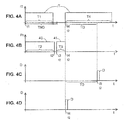
- the Figures 4A to 4D represent timing diagrams of signals in a differential protection device according to embodiments of the invention.
- a test signal ST is controlled for a duration T1 less than a non-triggering time TND.
- a first processing of the signals of the protection chains is carried out in particular at the beginning and at the end of a time T2. For example, at time t1, there is the determination of the state of the protection chains before or at the beginning of the test and at a time t2 the determination of the state of the protection chains after the test signal by a treatment 40.
- the analysis 41 of the test state begins for a period T3 and at a time t4 there is a decision to signal or to trigger the opening of an apparatus.
- Triggering can be done through the test signal by sending a test current for a time T4 greater than the tripping time TD.
- the device will trigger by a protection chain after a trip time TD at a time t5 as on the figure 4C .
- the trigger can be done directly by a relay control as on the figure 4D .
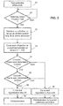
- the figure 5 represents a first differential protection test flow chart according to one embodiment of the invention.
- the protection test process differential has a first differential protection chain 7, a second differential protection chain 8, and a processing unit 22.
- a test phase begins.
- the method includes a step 51 for detecting the action on the test controller to initiate a test cycle.
- the control member is generally a push button on the front face of a device or a protective device.
- the method comprises a step 52 of inhibiting or selecting the long trip of the second differential protection channel before the circulation or injection control of said test signal.
- said second differential protection chain requiring a power supply is associated with the processing unit for the processing functions.
- a step 53 for controlling the flow of an IT current or for injecting a test signal of the differential protection for a predetermined duration T1 less than a non-tripping time TND of said first and said second differential protection chain.
- a step 54 determines the state of said first differential protection chain and controls the conformity of the operation of the protection. If the test is not good or not conclusive on the first chain, the process directs to a first treatment of the end of the test to handle a bad test. If the control of step 54 is good, a step 55 determines the state of said second differential protection chain and controls the conformity of the operation of the protection.
- the process directs to the first treatment of the end of the test to handle a bad test. If the control of step 55 is good, it means that both chains are working properly. The process directs to a second treatment of the end of the test to manage a good test. If the test is good, a step 56 indicates the end of the test including a light and / or communication and a step 57 causes a trigger opening of an electrical device to test also the mechanical part of the device . If the test is bad or is not compliant, a step 58 indicates the end of the test including a light and / or communication and then a reset step 59 resets a digital portion of the processing unit.
- steps 54 and 55 make the two grouped functions of determination of the states of the protections differential and the two compliance checks. However, these functions can be performed in separate steps, a step for determining the states and a step for the conformity check for each protection chain.
- the figure 6 represents a second differential protection test flow chart according to one embodiment of the invention.
- a step 60 detects an action on a push button for launching a manual test or a periodic automatic test.
- a step 61 determines the state of the first and second differential protection chain before the flow of a signal or test current.
- a step 62 calculates the duration of injection or circulation of the test current. In this case, the duration depends on the initial state of the protection, especially in case of fault current or residual leakage current.
- the test flow time T1 can be reduced to ensure that the device does not trip during the test.
- the test current flows during the previously calculated duration.
- a step 64 determines the state of the two differential protection chains after circulation of the test current.
- a step 65 determines the conformity of the evolution of the states of the two differential protection chains. If the test is good, a step 66 controls the triggering of an electrical device and / or the signaling of a correct test. If the test is bad or non-compliant, a step 67 controls the signaling of a bad test.
- the method controls a delay or filtering component 32 of said first differential protection chain that does not require power. electric.
- differential protection tests described above also apply to differential protections having more than two protection chains.
- the number of two chains is not a limitation but an illustration of the preferred embodiments.
- the embodiments described above show a triggering of the test by a manual action on a push button. This action is mainly used to trigger the opening of an electrical device. However, the test can also be triggered periodically automatically. In this case, local or remote signaling will be preferred.
- the test is made by generating a differential fault current by deriving a current between the upstream and the downstream of the current sensors.
- test signal generation are possible, in particular the use of additional test windings in differential current sensors and / or with generators powered and controlled by the processing unit.
- the electrical apparatus shown on the figure 1 is a bipolar device with two phase and neutral lines. However, the invention also applies to bipolar or tripolar or tetra polar apparatus.
Landscapes
- Physics & Mathematics (AREA)
- General Physics & Mathematics (AREA)
- Engineering & Computer Science (AREA)
- Power Engineering (AREA)
- Emergency Protection Circuit Devices (AREA)
Abstract
Description
- L'invention concerne un procédé de test de protection différentielle ayant une première chaine de protection différentielle, une seconde chaine de protection différentielle, et une unité de traitement.
- L'invention concerne aussi un dispositif de protection différentielle comportant :
- une première chaine de protection différentielle,
- une seconde chaine de protection différentielle,
- un dispositif de test pour tester lesdites chaines de protection différentielle, et
- une unité de traitement connectée à la seconde chaine de protection différentielle.
- L'invention concerne aussi un appareil de protection électrique comportant des contacts principaux, un mécanisme d'ouverture desdits contacts principaux, des conducteurs principaux connectés en série avec lesdits contacts principaux et un dispositif de protection différentielle ayant au moins deux chaines de protection différentielle.
- Il est connu d'utiliser l'injection de signaux pour tester des dispositifs de protection différentielle. Le but de ces tests est de vérifier le fonctionnement de la chaine de mesure et de déclenchement. La plupart des tests consistent à générer un signal de défaut différentiel et à constater le déclenchement ou l'ouverture d'un appareil électrique.
- Les dispositifs de test connus ne sont pas suffisants pour tester des dispositifs de protection différentiels complexes à plusieurs chaines de protection différentielle. Souvent, ces dispositifs complexes comportent une première chaine de protection à propre courant sans nécessité d'alimentation électrique extérieures et une seconde chaine plus complète en circuits électroniques nécessitant une alimentation électrique. Généralement, la première chaine détecte les défauts en courant alternatifs ou puisés, et la seconde chaine permet de détecter des défauts en courants continus, alternatifs ou puisés.
- Les circuits de test classiques injectent ou font circuler dans des tores de mesure un signal ou courant de défaut différentiel. Puis les chaines de traitement détectent le défaut et provoquent le déclenchement de l'ouverture d'un appareil électrique tel qu'un interrupteur ou un disjoncteur. Dans ce cas, lors du test, il suffit qu'une seule chaine de protection fonctionne pour faire déclencher. Par conséquent, le test n'est pas complet et ne reflète pas le bon fonctionnement total de l'ensemble des chaines de protection différentielle.
- L'invention a pour but un procédé de test et un dispositif de protection différentielle ayant un test amélioré des chaines de protection différentielles.
- Selon l'invention, un procédé de test de protection différentielle ayant une première chaine de protection différentielle, une seconde chaine de protection différentielle, et une unité de traitement comporte :
- une étape de commande de la circulation ou d'injection d'un signal de test de la protection différentielle pendant une durée prédéterminé inférieure à un temps de non déclenchement de ladite première et de ladite seconde chaines de protection différentielle,
- des étapes de détermination d'un état de ladite première et de ladite seconde chaine de protection différentielle après circulation d'un signal de test, de contrôle de la conformité de l'évolution des chaines de protection, et de détermination de l'état du test, et
- une étape de déclenchement ou de signalisation si le test est satisfaisant.
- Avantageusement, le procédé comporte pendant une phase de test :
- une étape de détermination de l'état de ladite première et de ladite seconde chaine de protection différentielle avant circulation d'un signal de test, et
- une étape de calcul de la durée d'injection du courant de test en fonction du résultat de la détermination de l'état desdites chaines de protection différentielle.
- De préférence, ladite seconde chaine de protection différentielle nécessitant une alimentation électrique est associée à l'unité de traitement, et le procédé comporte pendant la phase de test une étape d'inhibition ou de sélection de déclenchement long de la seconde chaine de protection différentielle avant la commande de circulation ou d'injection dudit signal de test.
- De préférence, lors d'étapes de détermination de l'état de ladite première chaine de traitement différentielle, le procédé contrôle un composant de temporisation ou de filtrage de ladite première chaine de protection différentielle ne nécessitant pas d'alimentation électrique.
- Avantageusement, le procédé comporte une étape de détection de l'action sur un organe de commande du test pour lancer manuellement un cycle de test et/ou des étapes pour lancer automatiquement de manière périodique ledit cycle de test.
- De préférence, le procédé comporte une étape de réinitialisation d'une partie numérique de l'unité de traitement si l'état du test n'est pas conforme.
- Selon l'invention, dans un dispositif de protection différentielle comportant :
- une première chaine de protection différentielle,
- une seconde chaine de protection différentielle,
- un dispositif de test pour tester lesdites chaines de protection différentielle, et
- une unité de traitement connectée à des modules de la seconde chaine de protection différentielle pour recevoir un signal représentatif du traitement de la dite seconde chaine,
- est connectée aussi à la première chaine de protection différentielle pour recevoir un signal représentatif de la protection différentielle et pour déterminer l'état de la protection de ladite première chaine,
- comporte une sortie pour commander la circulation d'un signal ou d'un courant de test pendant une durée prédéterminé inférieure à un temps de non déclenchement de ladite première et de ladite seconde chaines de protection différentielle,
- comporte des modules pour contrôler l'évolution des chaines de protection et détermine l'état du test, et
- commande le déclenchement de l'ouverture d'un appareil électrique ou une signalisation si le test est bon.
- Avantageusement, l'unité de traitement comporte des modules pour déterminer l'état de ladite première chaine et de ladite seconde chaine de protection différentielle avant la circulation d'un signal ou courant de test et pour commander le dispositif de test en fonction de l'état de la première et de la seconde chaine de protection différentielle.
- Avantageusement, la première chaine de protection différentielle est une chaine fonctionnant en courant de défaut alternatif ou pulsé ne nécessitant pas d'alimentation électrique pour son propre fonctionnement.
- Avantageusement, la seconde chaine de protection différentielle fonctionne pour des courants de défaut continus, alternatifs ou pulsés et est alimentée par une alimentation électrique, ladite unité de traitement étant associée à ladite seconde chaine de protection différentielle pour le traitement de la protection différentielle.
- De préférence, la première chaine de protection différentielle comporte un composant de temporisation ou de filtrage, ledit composant étant connecté à l'unité de traitement pour fournir un signal représentatif de l'état de la première chaine de protection différentielle.
- De préférence, le dispositif de protection différentielle comporte un organe de commande du test connecté à l'unité de traitement pour commander manuellement un cycle de test.
- Avantageusement, un déclenchement de l'ouverture d'un appareil est réalisé par une commande pendant un temps de circulation d'un courant de test supérieur à un temps de déclenchement de la première chaine de protection ou de la seconde chaine de protection.
- Avantageusement, un déclenchement de l'ouverture d'un appareil est réalisé par une commande directe d'un relais de déclenchement par ladite unité de traitement ou par une sortie de l'unité de traitement commandant la charge d'un condensateur utilisé aussi pour un stockage de l'énergie électrique de commande dudit relais de déclenchement.
- Selon l'invention, dans un appareil de protection électrique comportant des contacts principaux, un mécanisme d'ouverture desdits contacts principaux, des conducteurs principaux connectés en série avec lesdits contacts principaux et un dispositif de protection différentielle ayant au moins deux chaines de protection différentielle, ledit dispositif de protection différentielle est un dispositif tel que défini ci-dessus comportant des capteurs de courant pour lesdites chaines de protection différentielle entourant lesdits conducteurs principaux et fournissant des signaux représentatifs de courants de défaut différentiel, ledit mécanisme d'ouverture étant actionné par un relais de déclenchement en cas de détection de défaut différentiel ou de test concluant des dites chaines de protection différentielle.
- D'autres avantages et caractéristiques ressortiront plus clairement de la description qui va suivre, de modes particuliers de réalisation de l'invention, donnés à titre d'exemples non limitatifs, et représentés aux dessins annexés sur lesquels :
- la
figure 1 représente un schéma bloc d'un appareil électrique comportant un dispositif de protection différentiel selon l'art antérieur ; - la
figure 2 représente un schéma bloc d'un appareil électrique comportant un dispositif de protection différentiel selon un premier mode de réalisation de l'invention ; - la
figure 3 représente un schéma bloc d'un appareil électrique comportant un dispositif de protection différentiel selon un second mode de réalisation de l'invention ; - les
figures 4A à 4D représentent des chronogrammes de signaux dans un dispositif de protection différentiel selon des modes de réalisation de l'invention ; - la
figure 5 représente un premier organigramme de test de protection différentielle selon un mode de réalisation de l'invention ; et - la
figure 6 représente un second organigramme de test de protection différentielle selon un mode de réalisation de l'invention. - La
figure 1 représente un schéma bloc d'un appareil électrique 1 comportant un dispositif de test 2 d'un dispositif de protection différentielle selon un mode de réalisation connu. Ledit appareil de protection électrique comporte des contacts principaux 3, un mécanisme 4 d'ouverture desdits contacts principaux 3, des conducteurs principaux 5 connectés en série avec lesdits contacts principaux et un dispositif de protection différentielle 6 ayant au moins deux chaines de protection différentielle. Une première chaine 7 de protection différentielle à propre courant ne nécessite pas d'alimentation électrique externe et une seconde chaine de protection différentielle 8 est à alimentation électrique. La première chaine 7 comporte un premier module électronique de traitement 9 connecté à un premier capteur de mesure 10 tel qu'un transformateur ou un tore de mesure à circuit magnétique 11. Ledit transformateur ou tore 10 fournit un signal ou un courant de mesure Id1 sur un enroulement secondaire 13 représentatif d'un courant différentiel Id circulant dans les lignes des conducteurs principaux 5. Le capteur 10 de mesure entoure l'ensemble des conducteurs principaux 5 et fourni un courant de mesure Id1 pour la protection différentielle en courant alternatif ou pulsé. Le courant de mesure Id1 fourni par le tore est suffisant pour faire fonctionner le premier module de protection 9 et pour actionner le relais de déclenchement 12. La seconde chaine de protection différentielle 8 nécessite une alimentation électrique 14. Cette alimentation 14 est généralement connectée sur des lignes des conducteurs principaux 5 et comporte un convertisseur de tension pour alimenter des circuits électroniques de traitement. La seconde chaine 8 comporte un second module électronique de traitement 15 connecté à un second capteur de mesure 16. Le capteur 16 est généralement un capteur complexe à circuit magnétique 17 comportant un enroulement d'excitation 18 et un enroulement de mesure 19 fournissant un second signal de mesure Id2. Le capteur 16 de mesure entoure aussi l'ensemble des conducteurs principaux 5 et fourni un courant de mesure Id2 pour la protection différentielle de tous types de courants aussi bien continus alternatifs ou puisés. Le second circuit de traitement actionne également le relais de déclenchement 12 en cas de défaut différentiel. - Le test des chaines de protection se fait de manière classique en générant un courant différentiel entre l'amont et l'aval des capteurs de courant 10 et 16. Le dispositif de test 2 comporte une résistance 20 de limitation du courant de test et un bouton poussoir 21 de test connectés en série entre un premier conducteur de ligne amont et un second conducteur de ligne aval. Lorsque le test est commandé par l'action sur le bouton poussoir, un courant de défaut est généré et la chaine de traitement la plus concernée ou la plus rapide commande le déclenchement du relais 12 et l'ouverture des contacts 3 à travers le mécanisme 4. Ainsi, les deux chaines de protection ne sont pas testées lors d'un même test.
- Un dispositif de protection différentielle selon l'invention comporte un test des fonctions de protection différentielle permettant de tester au moins deux chaines de protection différentielle lors d'un même test. La
figure 2 représente un schéma bloc d'un appareil électrique bipolaire à deux lignes principales et comportant un dispositif de protection différentiel selon un premier mode de réalisation de l'invention. Le dispositif 6 de protection différentielle comporte une première chaine 7 de protection différentielle, une seconde chaine 8 de protection différentielle, un dispositif de test 2 pour tester les chaines de protection différentielle, et une unité de traitement 22 connectée à la seconde chaine 8 de protection différentielle. Dans ce mode de réalisation, l'unité de traitement est connectée aussi à la première chaine 7 de protection différentielle pour déterminer l'état de la protection. Ainsi, l'unité de traitement 22 comporte une entrée pour recevoir un signal S1, fourni par un premier module de traitement 9 et représentatif de l'état de la protection de la première chaine de protection. Un second signal S2 représentatif du fonctionnement de la seconde chaine 7 est fourni à l'unité de traitement par un second module 15. L'unité de traitement 22 a une sortie fournissant un signal ST pour commander la circulation d'un signal de test IT pendant une durée prédéterminé T1 inférieure à un temps de non déclenchement TND de ladite première et de ladite seconde chaines de protection différentielle. L'unité de traitement comporte des modules pour contrôler l'évolution des chaines de protection, déterminer l'état du test et commander le déclenchement de l'ouverture d'un appareil électrique si le test est bon. Le circuit de test comporte un interrupteur 23 commandé par le signal ST de test pour faire circuler le courant de défaut différentiel détecté par les capteurs de courant des deux chaines de protection. Le dispositif de lafigure 2 comporte un organe 21 de commande du test connecté à l'unité de traitement 22 pour commander manuellement un cycle de test. - L'unité de traitement comporte des modules pour déterminer l'état de ladite première chaine 7 et de ladite seconde chaine 8 de protection différentielle avant circulation d'un signal de test IT et pour commander le dispositif de test en fonction de l'état de la première et de la seconde chaine de protection différentielle. Après ou pendant la circulation du courant de test, les modules de l'unité de traitement contrôlent l'évolution des deux chaines de protection. Puis, si les évolutions des deux chaines sont conformes, ils signalent et ou commandent le déclenchement de l'ouverture d'un l'appareil. Sinon, une sortie de signalisation connectée à un indicateur 25 signale un test défaillant. Un circuit de communication 26 connecté à l'unité de traitement peut signaler aussi l'état de fonctionnement du test.
- De préférence, le déclenchement est réalisé par une commande pendant un temps T4 de circulation d'un courant de test IT supérieur à un temps de déclenchement TD de la première chaine de traitement et/ou de la seconde chaine de traitement. Une autre façon de commander le déclenchement est de commander directement le relais 12 par une sortie de l'unité de traitement. Sur la
figure 2 , le relais est commandé par un signal D directement par la première chaine de traitement ou par une sortie de l'unité de traitement. Dans ce cas, la seconde chaine de protection différentielle est aussi traitée par des modules numériques intégrés dans l'unité de traitement 22. - Dans ce mode de réalisation, la première chaine de protection différentielle 7 est une chaine dite à propre courant fonctionnant en courant de défaut alternatif ou pulsé et ne nécessitant pas une alimentation électrique pour son fonctionnement. La seconde chaine de protection différentielle 8 fonctionne pour des courants de défaut continu alternatifs ou pulsés et est alimentée par une alimentation électrique 14. Ladite unité de traitement 22 est de préférence associée à la seconde chaine de protection différentielle pour le traitement de la protection différentielle. L'alimentation 14 fournit l'énergie nécessaire pour faire fonctionner la seconde chaine de traitement et l'unité de traitement. Elle comporte une sortie de tension de référence 27 et au moins une sortie de ligne de tension d'alimentation V pour alimenter les circuits.
- La
figure 3 représente un schéma bloc d'un appareil électrique tétra polaire à quatre conducteurs de lignes comportant un dispositif de protection différentiel selon un second mode de réalisation de l'invention. La première chaine de protection différentielle 7 comporte dans le module 9 un redresseur 30 connecté à l'enroulement secondaire 13 du premier capteur 10, une résistance 31 connectée en sortie du redresseur et un condensateur 32 connecté à la résistance 31 et au redresseur. Le circuit résistance 31 et condensateur 32 effectue une temporisation pour le déclenchement de la première chaine de traitement. Le condensateur est connecté aussi à un comparateur 33 à seuil de tension pour commander un thyristor 34 ou un transistor de commande du relais 12 de déclenchement. L'énergie électrique accumulée dans le condensateur 32 est utilisée pour commander et alimenter le relais de déclenchement de la première chaine de traitement sans nécessiter d'alimentation supplémentaire. Seul le signal de mesure du premier capteur suffit à charger le condensateur 32 faisant office de temporisateur et de réserve d'énergie. Le condensateur 32 de par sa fonction de temporisation ou de filtrage a une tension représentative de la protection différentielle de la première chaine. Le condensateur 32 est avantageusement connecté à l'unité de traitement pour fournir le signal S1 représentatif de l'état de la première chaine de protection différentielle. Ainsi, le composant 32 de temporisation ou de filtrage est un condensateur utilisé aussi pour un stockage de l'énergie électrique de commande du relais de déclenchement. - La seconde chaine de traitement 8 comporte dans son module 15 un circuit de mesure de courant capable de mesurer des courants de défaut différentiel continus, alternatif ou pulsés par exemple des courants de fréquence allant de 0 Hz à plusieurs kHz. Ce circuit 35 envoie des signaux d'excitation sur un enroulement 18 du second capteur et mesure une valeur de courant sur un second enroulement 19. La fréquence de fonctionnement du circuit 35 est contrôlée par une connexion 36 avec l'unité de traitement. Le signal de mesure de la seconde chaine de traitement est filtré par un filtre passe bas 37 puis fourni par le signal S2 à l'unité de traitement.
- L'unité de traitement commande la circulation d'un signal ou un courant de test pendant un temps T1 de non déclenchement TND, puis elle détermine l'état de fonctionnement des deux chaines de traitement et détermine l'état du test. Si le test est bon, un déclenchement est commandé sinon il y a un signalement d'un test défectueux représentatif d'une chaine ne répondant pas de manière attendue au test. En fin de test, un premier voyant 25A connecté à l'unité de traitement signale un défaut de test et un second voyant 25B signale un test conforme ou bon. Dans un dispositif plus complexe, une mesure d'un courant de défaut différentiel préalable ou l'état préalable de l'état des chaines de protection permet de déterminer le temps de génération du signal de test qui sera inférieur au temps de déclenchement. Un défaut avant test pourrait réduire le temps de non déclenchement. De même, une mémorisation de l'état de la protection différentielle avant le test et la restitution d'un état compatible après le test est utile si le test est utilisé pour de la signalisation de bon fonctionnement.
- Le déclenchement du relais peut être réalisé par une commande directe du relais de déclenchement par l'unité de traitement. Sur le mode de réalisation de la
figure 3 , une sortie D2 de l'unité de traitement est connectée à un module 38 pour commander la charge du condensateur 32 utilisé aussi pour un stockage de l'énergie électrique de commande du relais 12 de déclenchement. Le déclenchement est fait alors de manière indirecte à travers le condensateur 32, le comparateur 33 et le thyristor 34. - Ainsi, un appareil de protection électrique selon un mode de réalisation de l'invention comporte des contacts principaux 3, un mécanisme 6 d'ouverture desdits contacts principaux 3, des conducteurs principaux connectés en série avec lesdits contacts principaux et un dispositif de protection différentielle ayant au moins deux chaines de protection différentielle, tel que défini ci-dessus.
- Les
figures 4A à 4D représentent des chronogrammes de signaux dans un dispositif de protection différentiel selon des modes de réalisation de l'invention. Sur lafigure 4A , à l'instant t1, un signal de test ST est commandé pendant une durée T1 inférieure à un temps de non déclenchement TND. Sur lafigure 4B , un premier traitement des signaux des chaines de protection est réalisé notamment au début et à la fin d'un temps T2. Par exemple, à l'instant t1, il y a la détermination de l'état des chaines de protection avant ou au début du test et à un instant t2 la détermination de l'état des chaines de protection après le signal de test par un traitement 40. A un instant t3, commence l'analyse 41 de l'état du test pendant une durée T3 et à un instant t4 il y a une décision de signaler ou de déclencher l'ouverture d'un appareil. Le déclenchement peut se faire à travers le signal de test en envoyant un courant de test pendant un temps T4 supérieur au temps de déclenchement TD. L'appareil déclenchera par une chaine de protection au bout d'un temps de déclenchement TD à un instant t5 comme sur lafigure 4C . Dans un autre mode de réalisation, le déclenchement peut se faire directement par une commande du relais comme sur lafigure 4D . - La
figure 5 représente un premier organigramme de test de protection différentielle selon un mode de réalisation de l'invention. Le procédé de test de protection différentielle a une première chaine 7 de protection différentielle, une seconde chaine 8 de protection différentielle, et une unité de traitement 22. A une étape 50, une phase de test commence. Lorsque le test est prévu pour être manuel, le procédé comporte une étape de détection 51 de l'action sur organe de commande du test pour lancer cycle de test. L'organe de commande est généralement un bouton poussoir en face avant d'un appareil ou d'un dispositif de protection. Pour allonger le temps de non déclenchement le procédé comporte une étape 52 d'inhibition ou de sélection de déclenchement long de la seconde chaine de protection différentielle avant la commande de circulation ou d'injection dudit signal de test. Pour faciliter le traitement, ladite seconde chaine de protection différentielle nécessitant une alimentation électrique est associée à l'unité de traitement pour les fonctions de traitement. Puis, il y a une étape 53 de commande de la circulation d'un courant IT ou d'injection d'un signal de test de la protection différentielle pendant une durée prédéterminé T1 inférieure à un temps de non déclenchement TND de ladite première et de ladite seconde chaine de protection différentielle. Après circulation d'un signal de test, une étape 54 détermine l'état de ladite première chaine de protection différentielle et contrôle la conformité du fonctionnement de la protection. Si le test n'est pas bon ou pas concluant sur la première chaine, le procédé oriente vers un premier traitement de la fin du test pour gérer un test mauvais. Si le contrôle de l'étape 54 est bon, une étape 55 détermine l'état de ladite seconde chaine de protection différentielle et contrôle la conformité du fonctionnement de la protection. Si le test n'est pas bon ou pas concluant sur la seconde chaine, le procédé oriente vers le premier traitement de la fin du test pour gérer un test mauvais. Si le contrôle de l'étape 55 est bon, cela signifie que les deux chaines fonctionnent correctement. Le procédé oriente vers un second traitement de la fin du test pour gérer un test bon. Si le test est bon, une étape 56 signale la fin du test notamment avec un voyant et/ou une communication et une étape 57 provoque un déclenchement de l'ouverture d'un appareil électrique permettant de tester aussi la partie mécanique de l'appareil. Si le test est mauvais ou n'est pas conforme, une étape 58 signale la fin du test notamment avec un voyant et/ou une communication puis une étape 59 de réinitialisation réinitialise une partie numérique de l'unité de traitement. Sur l'organigramme de lafigure 5 , les étapes 54 et 55 font les deux fonctions groupées de détermination des états des protections différentielles et les deux contrôles de conformité. Cependant, ces fonctions peuvent être réalisées en des étapes distinctes, une étape pour la détermination des états et une étape pour le contrôle de conformité pour chaque chaine de protection. - La
figure 6 représente un second organigramme de test de protection différentielle selon un mode de réalisation de l'invention. Sur cet organigramme, une étape 60 détecte une action sur un bouton poussoir de lancement d'un test manuel ou un test automatique périodique. Une étape 61 détermine l'état de la première et de la seconde chaine de protection différentielle avant la circulation d'un signal ou courant de test. Puis une étape 62 calcule la durée d'injection ou circulation du courant de test. Dans ce cas, la durée dépend de l'état initial de la protection, notamment en cas de courant de défaut ou de courant de fuite résiduel. Le temps T1 de circulation du test peut être réduit pour garantir un non déclenchement de l'appareil pendant le test. A une étape 63, le courant de test circule pendant la durée préalablement calculée. Puis une étape 64 détermine l'état des deux chaines de protection différentielle après circulation du courant de test. Une étape 65 détermine la conformité de l'évolution des états des deux chaines de protection différentielle. Si le test est bon, une étape 66 commande le déclenchement d'un appareil électrique et/ou la signalisation d'un test correct. Si le test est mauvais ou non conforme, une étape 67 commande la signalisation d'un mauvais test. - Pendant la phase de test, notamment lors des étapes 54, 61, ou 64, de détermination de la première chaine de traitement, le procédé contrôle un composant 32 de temporisation ou de filtrage de ladite première chaine de protection différentielle ne nécessitant pas d'alimentation électrique.
- Les tests de protection différentielle décrits ci-dessus s'appliquent aussi à des protections différentielles ayant plus de deux chaines de protection. Le nombre de deux chaines n'est pas une limitation mais une illustration des modes de réalisation préférés.
- Les modes de réalisation décrits ci-dessus montrent un déclenchement du test par une action manuelle sur un bouton poussoir. Cette action est surtout utilisée pour provoquer un déclenchement de l'ouverture d'un appareil électrique. Cependant, le test peut aussi être déclenché périodiquement de manière automatique. Dans ce cas, la signalisation locale ou à distance sera préférée.
- Dans les modes de réalisation décrits ci-dessus le test est fait par la génération d'un courant de défaut différentiel en dérivant un courant entre l'amont et l'aval des capteurs de courants. Cependant d'autres types de génération de signal de test sont possibles, notamment l'utilisation d'enroulements de test supplémentaires dans des capteurs de courant différentiel et/ou avec des générateurs alimentés et commandés par l'unité de traitement.
- L'appareil électrique représenté sur la
figure 1 est un appareil bipolaire avec deux lignes phase et neutre. Cependant, l'invention s'applique aussi à des appareils bipolaires ou tripolaires ou tétra polaires.
Claims (15)
- Procédé de test de protection différentielle ayant une première chaine (7) de protection différentielle, une seconde chaine (8) de protection différentielle, et une unité de traitement (22),
caractérisé en ce qu'il comporte :- une étape (53, 63) de commande de la circulation ou d'injection d'un signal de test de la protection différentielle pendant une durée (T1) prédéterminé inférieure à un temps (TND) de non déclenchement de ladite première et de ladite seconde chaines (7, 8) de protection différentielle,- des étapes (54, 55, 64, 65) de détermination d'un état de ladite première et de ladite seconde chaine de protection différentielle après circulation d'un signal de test, de contrôle de la conformité de l'évolution des chaines de protection, et de détermination de l'état du test, et- une étape (57, 59, 65, 67) de déclenchement ou de signalisation si le test est satisfaisant. - Procédé de test selon la revendication 1 caractérisé en ce qu'il comporte pendant une phase de test :- une étape (61) de détermination de l'état de ladite première et de ladite seconde chaine de protection différentielle avant circulation d'un signal de test, et- une étape (62) de calcul de la durée d'injection du courant de test en fonction du résultat de la détermination de l'état desdites chaines de protection différentielle.
- Procédé de test selon l'une des revendications 1 ou 2 caractérisé :- en ce que ladite seconde chaine de protection différentielle nécessitant une alimentation électrique est associée à l'unité de traitement, et- en ce qu'il comporte pendant la phase de test une étape (52) d'inhibition ou de sélection de déclenchement long de la seconde chaine de protection différentielle avant la commande de circulation ou d'injection dudit signal de test.
- Procédé de test selon l'une quelconque des revendications 1 à 3 caractérisé en ce que lors d'étapes de détermination de l'état de ladite première chaine de traitement différentielle, le procédé contrôle un composant (32) de temporisation ou de filtrage de ladite première chaine (7) de protection différentielle ne nécessitant pas d'alimentation électrique.
- Procédé de test selon l'une quelconque des revendications 1 à 4 caractérisé en ce qu'il comporte une étape (51, 60) de détection de l'action sur un organe de commande du test pour lancer manuellement un cycle de test et/ou des étapes pour lancer automatiquement de manière périodique ledit cycle de test.
- Procédé de test selon l'une quelconque des revendications 1 à 5 caractérisé en ce qu'il comporte une étape (59) de réinitialisation d'une partie numérique de l'unité de traitement si l'état du test n'est pas conforme.
- Dispositif (6) de protection différentielle comportant :- une première chaine (7) de protection différentielle,- une seconde chaine (8) de protection différentielle,- un dispositif de test (2) pour tester lesdites chaines de protection différentielle, et- une unité de traitement (22) connectée à des modules de la seconde chaine (8) de protection différentielle pour recevoir un signal (S2) représentatif du traitement de la dite seconde chaine,caractérisé en ce que ladite unité de traitement (22) :- est connectée aussi à la première chaine (7) de protection différentielle pour recevoir un signal (S1) représentatif de la protection différentielle et pour déterminer l'état de la protection de ladite première chaine,- comporte une sortie (ST) pour commander la circulation d'un signal ou d'un courant de test (IT) de test pendant une durée (T1) prédéterminé inférieure à un temps de non déclenchement (TND) de ladite première et de ladite seconde chaines (7, 8) de protection différentielle,- comporte des modules (22, 54, 55, 64, 65) pour contrôler l'évolution des chaines de protection et détermine l'état du test, et- commande le déclenchement (D) de l'ouverture d'un appareil électrique ou une signalisation si le test est bon.
- Dispositif de protection différentielle selon la revendication 7 caractérisé en ce que l'unité de traitement comporte des modules pour déterminer l'état de ladite première chaine (7) et de ladite seconde chaine (8) de protection différentielle avant circulation d'un signal ou courant de test (IT) et pour commander (ST) le dispositif de test en fonction de l'état de la première et de la seconde chaine de protection différentielle.
- Dispositif de protection différentielle selon l'une des revendications 7 ou 8 caractérisé en ce que la première chaine (7) de protection différentielle est une chaine fonctionnant en courant de défaut alternatif ou pulsé ne nécessitant pas d'alimentation électrique pour son propre fonctionnement.
- Dispositif de protection différentielle selon l'une quelconque des revendications 7 à 9 caractérisé en ce que la seconde chaine (8) de protection différentielle fonctionne pour des courants de défaut continus, alternatifs ou pulsés et est alimentée par une alimentation électrique (14), ladite unité de traitement (22) étant associée à ladite seconde chaine (8) de protection différentielle pour le traitement de la protection différentielle.
- Dispositif de protection différentielle selon l'une quelconque des revendications 7 à 10 caractérisé en ce que la première chaine (7) de protection différentielle comporte un composant (32) de temporisation ou de filtrage, ledit composant (32) étant connecté à l'unité de traitement (22) pour fournir un signal (S1) représentatif de l'état de la première chaine (7) de protection différentielle.
- Dispositif de protection différentielle selon l'une quelconque des revendications 7 à 11 caractérisé en ce qu'il comporte un organe (21) de commande du test connecté à l'unité de traitement (22) pour commander manuellement un cycle de test.
- Dispositif de test selon l'une quelconque des revendications 7 à 12 caractérisé en ce qu'un déclenchement de l'ouverture d'un appareil est réalisé par une commande (ST) pendant un temps (T4) de circulation d'un courant (IT) de test supérieur à un temps (TD) de déclenchement de la première chaine (7) de protection ou de la seconde chaine (8) de protection.
- Dispositif de test selon l'une quelconque des revendications 7 à 13 caractérisé en ce qu'un déclenchement de l'ouverture d'un appareil est réalisé par une commande (D) directe d'un relais (12) de déclenchement par ladite unité de traitement ou par une sortie (D2) de l'unité de traitement commandant la charge d'un condensateur (32) utilisé aussi pour un stockage de l'énergie électrique de commande dudit relais (12) de déclenchement.
- Appareil de protection électrique comportant des contacts principaux (3), un mécanisme (6) d'ouverture desdits contacts principaux (3), des conducteurs principaux connectés en série avec lesdits contacts principaux et un dispositif de protection différentielle ayant au moins deux chaines de protection différentielle, caractérisé en ce que ledit dispositif de protection différentielle est un dispositif selon l'une des revendications 7 à 14 comportant des capteurs (10, 16) de courant pour lesdites chaines (7, 8) de protection différentielle entourant lesdits conducteurs principaux (3) et fournissant des signaux représentatifs de courants de défaut différentiel, ledit mécanisme (6) d'ouverture étant actionné par un relais de déclenchement (12) en cas de détection de défaut différentiel ou de test concluant desdites chaines de protection différentielle.
Priority Applications (1)
| Application Number | Priority Date | Filing Date | Title |
|---|---|---|---|
| EP21198889.4A EP3958004A1 (fr) | 2017-12-19 | 2018-10-29 | Procédé de test de protection différentielle, dispositif de protection différentielle et appareil électrique comportant un tel dispositif |
Applications Claiming Priority (1)
| Application Number | Priority Date | Filing Date | Title |
|---|---|---|---|
| FR1762429A FR3075393B1 (fr) | 2017-12-19 | 2017-12-19 | Procede de test de protection differentielle, dispositif de protection differentielle et appareil electrique comportant un tel dispositif |
Related Child Applications (2)
| Application Number | Title | Priority Date | Filing Date |
|---|---|---|---|
| EP21198889.4A Division EP3958004A1 (fr) | 2017-12-19 | 2018-10-29 | Procédé de test de protection différentielle, dispositif de protection différentielle et appareil électrique comportant un tel dispositif |
| EP21198889.4A Division-Into EP3958004A1 (fr) | 2017-12-19 | 2018-10-29 | Procédé de test de protection différentielle, dispositif de protection différentielle et appareil électrique comportant un tel dispositif |
Publications (2)
| Publication Number | Publication Date |
|---|---|
| EP3502721A1 true EP3502721A1 (fr) | 2019-06-26 |
| EP3502721B1 EP3502721B1 (fr) | 2021-12-15 |
Family
ID=61187534
Family Applications (2)
| Application Number | Title | Priority Date | Filing Date |
|---|---|---|---|
| EP18203016.3A Active EP3502721B1 (fr) | 2017-12-19 | 2018-10-29 | Procede de test de protection differentielle, dispositif de protection differentielle et appareil electrique comportant un tel dispositif |
| EP21198889.4A Pending EP3958004A1 (fr) | 2017-12-19 | 2018-10-29 | Procédé de test de protection différentielle, dispositif de protection différentielle et appareil électrique comportant un tel dispositif |
Family Applications After (1)
| Application Number | Title | Priority Date | Filing Date |
|---|---|---|---|
| EP21198889.4A Pending EP3958004A1 (fr) | 2017-12-19 | 2018-10-29 | Procédé de test de protection différentielle, dispositif de protection différentielle et appareil électrique comportant un tel dispositif |
Country Status (5)
| Country | Link |
|---|---|
| US (1) | US11061078B2 (fr) |
| EP (2) | EP3502721B1 (fr) |
| CN (1) | CN109936116B (fr) |
| ES (1) | ES2906113T3 (fr) |
| FR (1) | FR3075393B1 (fr) |
Families Citing this family (8)
| Publication number | Priority date | Publication date | Assignee | Title |
|---|---|---|---|---|
| FR3111231B1 (fr) * | 2020-06-04 | 2022-07-29 | Schneider Electric Ind Sas | Méthode et dispositif de détection du déclenchement d’un appareil de coupure, et armoire électrique comprenant un tel dispositif |
| FR3112863B1 (fr) * | 2020-07-24 | 2023-05-26 | Schneider Electric Ind Sas | Procédés, dispositifs et systèmes pour détecter un défaut d’isolement dans une installation électrique |
| FR3116124B1 (fr) * | 2020-11-09 | 2022-10-14 | Safran Electrical & Power | Dispositifs de surveillance et de protection de circuits de puissance |
| CN112865018B (zh) * | 2021-01-08 | 2022-03-18 | 河海大学 | 一种储能电站多端汇流变压器保护方法 |
| CN113391098B (zh) * | 2021-06-15 | 2023-04-07 | 贵州电网有限责任公司 | 一种光差保护同轴电缆通道控制装置及其控制方法 |
| CN114779155B (zh) * | 2022-03-15 | 2025-07-15 | 国网江西省电力有限公司供电服务管理中心 | 电能表动态误差测量装置及系统 |
| CN117612846B (zh) * | 2023-10-26 | 2024-10-22 | 中建三局第三建设工程有限责任公司 | 一种变压器差动保护调试系统、方法 |
| FR3167781A1 (fr) * | 2024-10-21 | 2026-04-24 | Schneider Electric Industries Sas | Dispositif de protection, ensemble de protection, tableau électrique et méthode de test associés |
Citations (1)
| Publication number | Priority date | Publication date | Assignee | Title |
|---|---|---|---|---|
| WO2012040750A1 (fr) * | 2010-09-28 | 2012-04-05 | Eaton Gmbh | Interrupteur de protection de courant résiduel |
Family Cites Families (5)
| Publication number | Priority date | Publication date | Assignee | Title |
|---|---|---|---|---|
| FR2750266B1 (fr) * | 1996-06-20 | 1998-08-07 | Schneider Electric Sa | Dispositif de protection differentielle |
| US7843197B2 (en) * | 2004-06-15 | 2010-11-30 | Pass & Seymour, Inc. | Protective device with end-of-life indication before power denial |
| FR2862423B1 (fr) * | 2003-11-18 | 2005-12-30 | Schneider Electric Ind Sas | Dispositif et procede de protection differentielle et appareil electrique comportant un tel dispositif |
| FR2910189B1 (fr) * | 2006-12-18 | 2009-01-09 | Schneider Electric Ind Sas | Dispositif de protection differentielle. |
| WO2009097469A1 (fr) * | 2008-01-29 | 2009-08-06 | Leviton Manufacturing Co., Inc. | Appareil et procédé d'interrupteur de circuit détecteur de défaut à autocontrôle |
-
2017
- 2017-12-19 FR FR1762429A patent/FR3075393B1/fr not_active Expired - Fee Related
-
2018
- 2018-10-29 ES ES18203016T patent/ES2906113T3/es active Active
- 2018-10-29 EP EP18203016.3A patent/EP3502721B1/fr active Active
- 2018-10-29 EP EP21198889.4A patent/EP3958004A1/fr active Pending
- 2018-11-14 US US16/190,241 patent/US11061078B2/en active Active
- 2018-12-04 CN CN201811473023.9A patent/CN109936116B/zh active Active
Patent Citations (1)
| Publication number | Priority date | Publication date | Assignee | Title |
|---|---|---|---|---|
| WO2012040750A1 (fr) * | 2010-09-28 | 2012-04-05 | Eaton Gmbh | Interrupteur de protection de courant résiduel |
Also Published As
| Publication number | Publication date |
|---|---|
| US20190190247A1 (en) | 2019-06-20 |
| CN109936116B (zh) | 2022-12-20 |
| ES2906113T3 (es) | 2022-04-13 |
| US11061078B2 (en) | 2021-07-13 |
| EP3958004A1 (fr) | 2022-02-23 |
| EP3502721B1 (fr) | 2021-12-15 |
| FR3075393B1 (fr) | 2019-11-29 |
| FR3075393A1 (fr) | 2019-06-21 |
| CN109936116A (zh) | 2019-06-25 |
Similar Documents
| Publication | Publication Date | Title |
|---|---|---|
| FR3075393B1 (fr) | Procede de test de protection differentielle, dispositif de protection differentielle et appareil electrique comportant un tel dispositif | |
| FR3009624A1 (fr) | Test integre de detecteur d'amorcages d'arcs/phenomenes transitoires | |
| FR2504749A1 (fr) | Dispositif de protection de charge a semi-conducteurs avec une faculte d'essai | |
| WO2019110711A1 (fr) | Procede de detection de l'etat d'un appareil de protection electrique dans une installation electrique et dispositif de detection mettant en oeuvre ledit procede | |
| FR3059462A1 (fr) | Appareil de protection electrique a bouton test | |
| FR2942352A1 (fr) | Identification et protection d'un systeme de courant c.a-c.c aerospatial en presence de contenu de courant c.c en raison des charges defectueuses | |
| EP2267465A1 (fr) | Dispositif et procédé d'indication de défauts électriques, ensemble et tableau électrique comportant un tel dispositif | |
| EP0723325A1 (fr) | Dispositif de contrÔle-commande d'un système électrique | |
| FR2682190A1 (fr) | Procede de detection selective d'un defaut resistant dans un reseau de distribution d'energie electrique et dispositif pour sa mise en óoeuvre. | |
| FR3017957A1 (fr) | Module de courant et de tension et procedes de surveillance de courant et de tension dans des reseaux de distribution d'energie | |
| EP4241353B1 (fr) | Dispositifs de surveillance et de protection de circuits de puissance | |
| FR3067514A1 (fr) | Liaison electrique comprenant un dispositif de protection electrique - test d'integrite | |
| EP2980941B1 (fr) | Dispositif d'adaptation d'un signal d'alimentation électrique, système d'alimentation électrique et procédé d'adaptation d'un signal d'alimentation électrique associés | |
| EP0129454B1 (fr) | Procédé de mesure de l'autonomie d'une alimentation électrique à découpage et dispositif pour sa mise en oeuvre | |
| EP3381100B1 (fr) | Procède et dispositif de mise sous tension d'un transformateur de puissance | |
| EP3438681B1 (fr) | Procede et dispositif de test de protection arc electrique et appareil electrique comportant un tel dispositif | |
| FR2990305A1 (fr) | Procede de protection d'un boitier de distribution d'energie electrique | |
| FR2870996A1 (fr) | Protection de circuit electrique en mode veille pour vehicule | |
| FR2624646A1 (fr) | ||
| EP1912303B1 (fr) | Dispositif permettant d'intervenir sur un organe de coupure associé à un dispositif différentiel résiduel en assurant la continuité de l'alimentation électrique d'une charge située en aval | |
| EP3650875A1 (fr) | Procede de test d'un appareil de protection electrique et appareil de protection mettant en oeuvre un tel procede | |
| EP4432499A1 (fr) | Procédé et système de protection d'un réseau de distribution électrique comportant au moins deux sources d énergie électrique | |
| FR2872581A1 (fr) | Dispositif de test du fonctionnement d'un controleur d'isolement d'installations electriques | |
| NO316141B1 (no) | Anordning og fremgangsmåte for å avdekke svake kontaktforbindelser |
Legal Events
| Date | Code | Title | Description |
|---|---|---|---|
| PUAI | Public reference made under article 153(3) epc to a published international application that has entered the european phase |
Free format text: ORIGINAL CODE: 0009012 |
|
| STAA | Information on the status of an ep patent application or granted ep patent |
Free format text: STATUS: THE APPLICATION HAS BEEN PUBLISHED |
|
| AK | Designated contracting states |
Kind code of ref document: A1 Designated state(s): AL AT BE BG CH CY CZ DE DK EE ES FI FR GB GR HR HU IE IS IT LI LT LU LV MC MK MT NL NO PL PT RO RS SE SI SK SM TR |
|
| AX | Request for extension of the european patent |
Extension state: BA ME |
|
| STAA | Information on the status of an ep patent application or granted ep patent |
Free format text: STATUS: REQUEST FOR EXAMINATION WAS MADE |
|
| 17P | Request for examination filed |
Effective date: 20190704 |
|
| RBV | Designated contracting states (corrected) |
Designated state(s): AL AT BE BG CH CY CZ DE DK EE ES FI FR GB GR HR HU IE IS IT LI LT LU LV MC MK MT NL NO PL PT RO RS SE SI SK SM TR |
|
| RIC1 | Information provided on ipc code assigned before grant |
Ipc: G01R 31/52 20200101AFI20200630BHEP Ipc: G01R 35/00 20060101ALI20200630BHEP Ipc: H02H 3/33 20060101ALI20200630BHEP Ipc: H02H 3/04 20060101ALI20200630BHEP Ipc: H02H 3/05 20060101ALI20200630BHEP |
|
| GRAP | Despatch of communication of intention to grant a patent |
Free format text: ORIGINAL CODE: EPIDOSNIGR1 |
|
| STAA | Information on the status of an ep patent application or granted ep patent |
Free format text: STATUS: GRANT OF PATENT IS INTENDED |
|
| INTG | Intention to grant announced |
Effective date: 20201106 |
|
| RIN1 | Information on inventor provided before grant (corrected) |
Inventor name: BERNARD, JEAN-BAPTISTE Inventor name: VINCENT, FRANCOIS Inventor name: TIAN, SIMON Inventor name: MEUNIER-CARUS, JEROME |
|
| GRAJ | Information related to disapproval of communication of intention to grant by the applicant or resumption of examination proceedings by the epo deleted |
Free format text: ORIGINAL CODE: EPIDOSDIGR1 |
|
| STAA | Information on the status of an ep patent application or granted ep patent |
Free format text: STATUS: REQUEST FOR EXAMINATION WAS MADE |
|
| INTC | Intention to grant announced (deleted) | ||
| GRAP | Despatch of communication of intention to grant a patent |
Free format text: ORIGINAL CODE: EPIDOSNIGR1 |
|
| STAA | Information on the status of an ep patent application or granted ep patent |
Free format text: STATUS: GRANT OF PATENT IS INTENDED |
|
| INTG | Intention to grant announced |
Effective date: 20210219 |
|
| GRAJ | Information related to disapproval of communication of intention to grant by the applicant or resumption of examination proceedings by the epo deleted |
Free format text: ORIGINAL CODE: EPIDOSDIGR1 |
|
| STAA | Information on the status of an ep patent application or granted ep patent |
Free format text: STATUS: REQUEST FOR EXAMINATION WAS MADE |
|
| REG | Reference to a national code |
Ref country code: DE Ref legal event code: R079 Ref document number: 602018028128 Country of ref document: DE Free format text: PREVIOUS MAIN CLASS: G01R0031327000 Ipc: G01R0031520000 |
|
| GRAP | Despatch of communication of intention to grant a patent |
Free format text: ORIGINAL CODE: EPIDOSNIGR1 |
|
| STAA | Information on the status of an ep patent application or granted ep patent |
Free format text: STATUS: GRANT OF PATENT IS INTENDED |
|
| INTC | Intention to grant announced (deleted) | ||
| RIC1 | Information provided on ipc code assigned before grant |
Ipc: G01R 31/52 20200101AFI20210421BHEP Ipc: H02H 3/04 20060101ALI20210421BHEP Ipc: H02H 3/33 20060101ALI20210421BHEP Ipc: H02H 3/05 20060101ALI20210421BHEP Ipc: G01R 35/00 20060101ALI20210421BHEP Ipc: G01R 31/50 20200101ALI20210421BHEP |
|
| INTG | Intention to grant announced |
Effective date: 20210506 |
|
| GRAJ | Information related to disapproval of communication of intention to grant by the applicant or resumption of examination proceedings by the epo deleted |
Free format text: ORIGINAL CODE: EPIDOSDIGR1 |
|
| GRAP | Despatch of communication of intention to grant a patent |
Free format text: ORIGINAL CODE: EPIDOSNIGR1 |
|
| INTG | Intention to grant announced |
Effective date: 20210708 |
|
| GRAS | Grant fee paid |
Free format text: ORIGINAL CODE: EPIDOSNIGR3 |
|
| GRAA | (expected) grant |
Free format text: ORIGINAL CODE: 0009210 |
|
| STAA | Information on the status of an ep patent application or granted ep patent |
Free format text: STATUS: THE PATENT HAS BEEN GRANTED |
|
| AK | Designated contracting states |
Kind code of ref document: B1 Designated state(s): AL AT BE BG CH CY CZ DE DK EE ES FI FR GB GR HR HU IE IS IT LI LT LU LV MC MK MT NL NO PL PT RO RS SE SI SK SM TR |
|
| REG | Reference to a national code |
Ref country code: GB Ref legal event code: FG4D Free format text: NOT ENGLISH Ref country code: CH Ref legal event code: EP |
|
| REG | Reference to a national code |
Ref country code: IE Ref legal event code: FG4D Free format text: LANGUAGE OF EP DOCUMENT: FRENCH Ref country code: DE Ref legal event code: R096 Ref document number: 602018028128 Country of ref document: DE |
|
| REG | Reference to a national code |
Ref country code: AT Ref legal event code: REF Ref document number: 1455887 Country of ref document: AT Kind code of ref document: T Effective date: 20220115 |
|
| REG | Reference to a national code |
Ref country code: LT Ref legal event code: MG9D |
|
| REG | Reference to a national code |
Ref country code: ES Ref legal event code: FG2A Ref document number: 2906113 Country of ref document: ES Kind code of ref document: T3 Effective date: 20220413 |
|
| REG | Reference to a national code |
Ref country code: NL Ref legal event code: MP Effective date: 20211215 |
|
| PG25 | Lapsed in a contracting state [announced via postgrant information from national office to epo] |
Ref country code: RS Free format text: LAPSE BECAUSE OF FAILURE TO SUBMIT A TRANSLATION OF THE DESCRIPTION OR TO PAY THE FEE WITHIN THE PRESCRIBED TIME-LIMIT Effective date: 20211215 Ref country code: LT Free format text: LAPSE BECAUSE OF FAILURE TO SUBMIT A TRANSLATION OF THE DESCRIPTION OR TO PAY THE FEE WITHIN THE PRESCRIBED TIME-LIMIT Effective date: 20211215 Ref country code: FI Free format text: LAPSE BECAUSE OF FAILURE TO SUBMIT A TRANSLATION OF THE DESCRIPTION OR TO PAY THE FEE WITHIN THE PRESCRIBED TIME-LIMIT Effective date: 20211215 Ref country code: BG Free format text: LAPSE BECAUSE OF FAILURE TO SUBMIT A TRANSLATION OF THE DESCRIPTION OR TO PAY THE FEE WITHIN THE PRESCRIBED TIME-LIMIT Effective date: 20220315 |
|
| REG | Reference to a national code |
Ref country code: AT Ref legal event code: MK05 Ref document number: 1455887 Country of ref document: AT Kind code of ref document: T Effective date: 20211215 |
|
| PG25 | Lapsed in a contracting state [announced via postgrant information from national office to epo] |
Ref country code: SE Free format text: LAPSE BECAUSE OF FAILURE TO SUBMIT A TRANSLATION OF THE DESCRIPTION OR TO PAY THE FEE WITHIN THE PRESCRIBED TIME-LIMIT Effective date: 20211215 Ref country code: NO Free format text: LAPSE BECAUSE OF FAILURE TO SUBMIT A TRANSLATION OF THE DESCRIPTION OR TO PAY THE FEE WITHIN THE PRESCRIBED TIME-LIMIT Effective date: 20220315 Ref country code: LV Free format text: LAPSE BECAUSE OF FAILURE TO SUBMIT A TRANSLATION OF THE DESCRIPTION OR TO PAY THE FEE WITHIN THE PRESCRIBED TIME-LIMIT Effective date: 20211215 Ref country code: HR Free format text: LAPSE BECAUSE OF FAILURE TO SUBMIT A TRANSLATION OF THE DESCRIPTION OR TO PAY THE FEE WITHIN THE PRESCRIBED TIME-LIMIT Effective date: 20211215 Ref country code: GR Free format text: LAPSE BECAUSE OF FAILURE TO SUBMIT A TRANSLATION OF THE DESCRIPTION OR TO PAY THE FEE WITHIN THE PRESCRIBED TIME-LIMIT Effective date: 20220316 |
|
| PG25 | Lapsed in a contracting state [announced via postgrant information from national office to epo] |
Ref country code: NL Free format text: LAPSE BECAUSE OF FAILURE TO SUBMIT A TRANSLATION OF THE DESCRIPTION OR TO PAY THE FEE WITHIN THE PRESCRIBED TIME-LIMIT Effective date: 20211215 |
|
| PG25 | Lapsed in a contracting state [announced via postgrant information from national office to epo] |
Ref country code: SM Free format text: LAPSE BECAUSE OF FAILURE TO SUBMIT A TRANSLATION OF THE DESCRIPTION OR TO PAY THE FEE WITHIN THE PRESCRIBED TIME-LIMIT Effective date: 20211215 Ref country code: SK Free format text: LAPSE BECAUSE OF FAILURE TO SUBMIT A TRANSLATION OF THE DESCRIPTION OR TO PAY THE FEE WITHIN THE PRESCRIBED TIME-LIMIT Effective date: 20211215 Ref country code: RO Free format text: LAPSE BECAUSE OF FAILURE TO SUBMIT A TRANSLATION OF THE DESCRIPTION OR TO PAY THE FEE WITHIN THE PRESCRIBED TIME-LIMIT Effective date: 20211215 Ref country code: PT Free format text: LAPSE BECAUSE OF FAILURE TO SUBMIT A TRANSLATION OF THE DESCRIPTION OR TO PAY THE FEE WITHIN THE PRESCRIBED TIME-LIMIT Effective date: 20220418 Ref country code: EE Free format text: LAPSE BECAUSE OF FAILURE TO SUBMIT A TRANSLATION OF THE DESCRIPTION OR TO PAY THE FEE WITHIN THE PRESCRIBED TIME-LIMIT Effective date: 20211215 Ref country code: CZ Free format text: LAPSE BECAUSE OF FAILURE TO SUBMIT A TRANSLATION OF THE DESCRIPTION OR TO PAY THE FEE WITHIN THE PRESCRIBED TIME-LIMIT Effective date: 20211215 |
|
| PG25 | Lapsed in a contracting state [announced via postgrant information from national office to epo] |
Ref country code: PL Free format text: LAPSE BECAUSE OF FAILURE TO SUBMIT A TRANSLATION OF THE DESCRIPTION OR TO PAY THE FEE WITHIN THE PRESCRIBED TIME-LIMIT Effective date: 20211215 Ref country code: AT Free format text: LAPSE BECAUSE OF FAILURE TO SUBMIT A TRANSLATION OF THE DESCRIPTION OR TO PAY THE FEE WITHIN THE PRESCRIBED TIME-LIMIT Effective date: 20211215 |
|
| REG | Reference to a national code |
Ref country code: DE Ref legal event code: R097 Ref document number: 602018028128 Country of ref document: DE |
|
| PG25 | Lapsed in a contracting state [announced via postgrant information from national office to epo] |
Ref country code: IS Free format text: LAPSE BECAUSE OF FAILURE TO SUBMIT A TRANSLATION OF THE DESCRIPTION OR TO PAY THE FEE WITHIN THE PRESCRIBED TIME-LIMIT Effective date: 20220415 |
|
| PLBE | No opposition filed within time limit |
Free format text: ORIGINAL CODE: 0009261 |
|
| STAA | Information on the status of an ep patent application or granted ep patent |
Free format text: STATUS: NO OPPOSITION FILED WITHIN TIME LIMIT |
|
| PG25 | Lapsed in a contracting state [announced via postgrant information from national office to epo] |
Ref country code: DK Free format text: LAPSE BECAUSE OF FAILURE TO SUBMIT A TRANSLATION OF THE DESCRIPTION OR TO PAY THE FEE WITHIN THE PRESCRIBED TIME-LIMIT Effective date: 20211215 Ref country code: AL Free format text: LAPSE BECAUSE OF FAILURE TO SUBMIT A TRANSLATION OF THE DESCRIPTION OR TO PAY THE FEE WITHIN THE PRESCRIBED TIME-LIMIT Effective date: 20211215 |
|
| 26N | No opposition filed |
Effective date: 20220916 |
|
| PG25 | Lapsed in a contracting state [announced via postgrant information from national office to epo] |
Ref country code: SI Free format text: LAPSE BECAUSE OF FAILURE TO SUBMIT A TRANSLATION OF THE DESCRIPTION OR TO PAY THE FEE WITHIN THE PRESCRIBED TIME-LIMIT Effective date: 20211215 |
|
| PG25 | Lapsed in a contracting state [announced via postgrant information from national office to epo] |
Ref country code: MC Free format text: LAPSE BECAUSE OF FAILURE TO SUBMIT A TRANSLATION OF THE DESCRIPTION OR TO PAY THE FEE WITHIN THE PRESCRIBED TIME-LIMIT Effective date: 20211215 |
|
| REG | Reference to a national code |
Ref country code: CH Ref legal event code: PL |
|
| REG | Reference to a national code |
Ref country code: BE Ref legal event code: MM Effective date: 20221031 |
|
| PG25 | Lapsed in a contracting state [announced via postgrant information from national office to epo] |
Ref country code: LU Free format text: LAPSE BECAUSE OF NON-PAYMENT OF DUE FEES Effective date: 20221029 |
|
| PG25 | Lapsed in a contracting state [announced via postgrant information from national office to epo] |
Ref country code: LI Free format text: LAPSE BECAUSE OF NON-PAYMENT OF DUE FEES Effective date: 20221031 Ref country code: CH Free format text: LAPSE BECAUSE OF NON-PAYMENT OF DUE FEES Effective date: 20221031 |
|
| PG25 | Lapsed in a contracting state [announced via postgrant information from national office to epo] |
Ref country code: BE Free format text: LAPSE BECAUSE OF NON-PAYMENT OF DUE FEES Effective date: 20221031 |
|
| PG25 | Lapsed in a contracting state [announced via postgrant information from national office to epo] |
Ref country code: IE Free format text: LAPSE BECAUSE OF NON-PAYMENT OF DUE FEES Effective date: 20221029 |
|
| PG25 | Lapsed in a contracting state [announced via postgrant information from national office to epo] |
Ref country code: HU Free format text: LAPSE BECAUSE OF FAILURE TO SUBMIT A TRANSLATION OF THE DESCRIPTION OR TO PAY THE FEE WITHIN THE PRESCRIBED TIME-LIMIT; INVALID AB INITIO Effective date: 20181029 |
|
| PG25 | Lapsed in a contracting state [announced via postgrant information from national office to epo] |
Ref country code: CY Free format text: LAPSE BECAUSE OF FAILURE TO SUBMIT A TRANSLATION OF THE DESCRIPTION OR TO PAY THE FEE WITHIN THE PRESCRIBED TIME-LIMIT Effective date: 20211215 |
|
| PG25 | Lapsed in a contracting state [announced via postgrant information from national office to epo] |
Ref country code: MK Free format text: LAPSE BECAUSE OF FAILURE TO SUBMIT A TRANSLATION OF THE DESCRIPTION OR TO PAY THE FEE WITHIN THE PRESCRIBED TIME-LIMIT Effective date: 20211215 |
|
| PG25 | Lapsed in a contracting state [announced via postgrant information from national office to epo] |
Ref country code: MT Free format text: LAPSE BECAUSE OF FAILURE TO SUBMIT A TRANSLATION OF THE DESCRIPTION OR TO PAY THE FEE WITHIN THE PRESCRIBED TIME-LIMIT Effective date: 20211215 |
|
| PGFP | Annual fee paid to national office [announced via postgrant information from national office to epo] |
Ref country code: IT Payment date: 20241022 Year of fee payment: 7 Ref country code: ES Payment date: 20241118 Year of fee payment: 7 |
|
| PG25 | Lapsed in a contracting state [announced via postgrant information from national office to epo] |
Ref country code: TR Free format text: LAPSE BECAUSE OF FAILURE TO SUBMIT A TRANSLATION OF THE DESCRIPTION OR TO PAY THE FEE WITHIN THE PRESCRIBED TIME-LIMIT Effective date: 20211215 |
|
| PGFP | Annual fee paid to national office [announced via postgrant information from national office to epo] |
Ref country code: DE Payment date: 20251028 Year of fee payment: 8 |
|
| PGFP | Annual fee paid to national office [announced via postgrant information from national office to epo] |
Ref country code: GB Payment date: 20251017 Year of fee payment: 8 |
|
| PGFP | Annual fee paid to national office [announced via postgrant information from national office to epo] |
Ref country code: FR Payment date: 20251030 Year of fee payment: 8 |