EP3502600A1 - Refrigerator door and method of manufacturing same - Google Patents
Refrigerator door and method of manufacturing same Download PDFInfo
- Publication number
- EP3502600A1 EP3502600A1 EP16914078.7A EP16914078A EP3502600A1 EP 3502600 A1 EP3502600 A1 EP 3502600A1 EP 16914078 A EP16914078 A EP 16914078A EP 3502600 A1 EP3502600 A1 EP 3502600A1
- Authority
- EP
- European Patent Office
- Prior art keywords
- light
- logo display
- display area
- frame
- refrigerator door
- Prior art date
- Legal status (The legal status is an assumption and is not a legal conclusion. Google has not performed a legal analysis and makes no representation as to the accuracy of the status listed.)
- Granted
Links
Images
Classifications
-
- F—MECHANICAL ENGINEERING; LIGHTING; HEATING; WEAPONS; BLASTING
- F25—REFRIGERATION OR COOLING; COMBINED HEATING AND REFRIGERATION SYSTEMS; HEAT PUMP SYSTEMS; MANUFACTURE OR STORAGE OF ICE; LIQUEFACTION SOLIDIFICATION OF GASES
- F25D—REFRIGERATORS; COLD ROOMS; ICE-BOXES; COOLING OR FREEZING APPARATUS NOT OTHERWISE PROVIDED FOR
- F25D23/00—General constructional features
- F25D23/02—Doors; Covers
-
- F—MECHANICAL ENGINEERING; LIGHTING; HEATING; WEAPONS; BLASTING
- F25—REFRIGERATION OR COOLING; COMBINED HEATING AND REFRIGERATION SYSTEMS; HEAT PUMP SYSTEMS; MANUFACTURE OR STORAGE OF ICE; LIQUEFACTION SOLIDIFICATION OF GASES
- F25D—REFRIGERATORS; COLD ROOMS; ICE-BOXES; COOLING OR FREEZING APPARATUS NOT OTHERWISE PROVIDED FOR
- F25D23/00—General constructional features
- F25D23/02—Doors; Covers
- F25D23/028—Details
-
- F—MECHANICAL ENGINEERING; LIGHTING; HEATING; WEAPONS; BLASTING
- F21—LIGHTING
- F21V—FUNCTIONAL FEATURES OR DETAILS OF LIGHTING DEVICES OR SYSTEMS THEREOF; STRUCTURAL COMBINATIONS OF LIGHTING DEVICES WITH OTHER ARTICLES, NOT OTHERWISE PROVIDED FOR
- F21V33/00—Structural combinations of lighting devices with other articles, not otherwise provided for
- F21V33/0004—Personal or domestic articles
- F21V33/0044—Household appliances, e.g. washing machines or vacuum cleaners
-
- F—MECHANICAL ENGINEERING; LIGHTING; HEATING; WEAPONS; BLASTING
- F25—REFRIGERATION OR COOLING; COMBINED HEATING AND REFRIGERATION SYSTEMS; HEAT PUMP SYSTEMS; MANUFACTURE OR STORAGE OF ICE; LIQUEFACTION SOLIDIFICATION OF GASES
- F25D—REFRIGERATORS; COLD ROOMS; ICE-BOXES; COOLING OR FREEZING APPARATUS NOT OTHERWISE PROVIDED FOR
- F25D29/00—Arrangement or mounting of control or safety devices
- F25D29/003—Arrangement or mounting of control or safety devices for movable devices
-
- F—MECHANICAL ENGINEERING; LIGHTING; HEATING; WEAPONS; BLASTING
- F25—REFRIGERATION OR COOLING; COMBINED HEATING AND REFRIGERATION SYSTEMS; HEAT PUMP SYSTEMS; MANUFACTURE OR STORAGE OF ICE; LIQUEFACTION SOLIDIFICATION OF GASES
- F25D—REFRIGERATORS; COLD ROOMS; ICE-BOXES; COOLING OR FREEZING APPARATUS NOT OTHERWISE PROVIDED FOR
- F25D29/00—Arrangement or mounting of control or safety devices
- F25D29/005—Mounting of control devices
-
- F—MECHANICAL ENGINEERING; LIGHTING; HEATING; WEAPONS; BLASTING
- F21—LIGHTING
- F21W—INDEXING SCHEME ASSOCIATED WITH SUBCLASSES F21K, F21L, F21S and F21V, RELATING TO USES OR APPLICATIONS OF LIGHTING DEVICES OR SYSTEMS
- F21W2131/00—Use or application of lighting devices or systems not provided for in codes F21W2102/00-F21W2121/00
- F21W2131/30—Lighting for domestic or personal use
- F21W2131/305—Lighting for domestic or personal use for refrigerators
-
- F—MECHANICAL ENGINEERING; LIGHTING; HEATING; WEAPONS; BLASTING
- F25—REFRIGERATION OR COOLING; COMBINED HEATING AND REFRIGERATION SYSTEMS; HEAT PUMP SYSTEMS; MANUFACTURE OR STORAGE OF ICE; LIQUEFACTION SOLIDIFICATION OF GASES
- F25D—REFRIGERATORS; COLD ROOMS; ICE-BOXES; COOLING OR FREEZING APPARATUS NOT OTHERWISE PROVIDED FOR
- F25D2323/00—General constructional features not provided for in other groups of this subclass
- F25D2323/02—Details of doors or covers not otherwise covered
-
- F—MECHANICAL ENGINEERING; LIGHTING; HEATING; WEAPONS; BLASTING
- F25—REFRIGERATION OR COOLING; COMBINED HEATING AND REFRIGERATION SYSTEMS; HEAT PUMP SYSTEMS; MANUFACTURE OR STORAGE OF ICE; LIQUEFACTION SOLIDIFICATION OF GASES
- F25D—REFRIGERATORS; COLD ROOMS; ICE-BOXES; COOLING OR FREEZING APPARATUS NOT OTHERWISE PROVIDED FOR
- F25D2400/00—General features of, or devices for refrigerators, cold rooms, ice-boxes, or for cooling or freezing apparatus not covered by any other subclass
- F25D2400/18—Aesthetic features
-
- F—MECHANICAL ENGINEERING; LIGHTING; HEATING; WEAPONS; BLASTING
- F25—REFRIGERATION OR COOLING; COMBINED HEATING AND REFRIGERATION SYSTEMS; HEAT PUMP SYSTEMS; MANUFACTURE OR STORAGE OF ICE; LIQUEFACTION SOLIDIFICATION OF GASES
- F25D—REFRIGERATORS; COLD ROOMS; ICE-BOXES; COOLING OR FREEZING APPARATUS NOT OTHERWISE PROVIDED FOR
- F25D2400/00—General features of, or devices for refrigerators, cold rooms, ice-boxes, or for cooling or freezing apparatus not covered by any other subclass
- F25D2400/36—Visual displays
-
- F—MECHANICAL ENGINEERING; LIGHTING; HEATING; WEAPONS; BLASTING
- F25—REFRIGERATION OR COOLING; COMBINED HEATING AND REFRIGERATION SYSTEMS; HEAT PUMP SYSTEMS; MANUFACTURE OR STORAGE OF ICE; LIQUEFACTION SOLIDIFICATION OF GASES
- F25D—REFRIGERATORS; COLD ROOMS; ICE-BOXES; COOLING OR FREEZING APPARATUS NOT OTHERWISE PROVIDED FOR
- F25D2700/00—Means for sensing or measuring; Sensors therefor
- F25D2700/04—Sensors detecting the presence of a person
Definitions
- the present invention relates to a refrigerator door and a manufacturing method thereof.
- LOGOs formed through the above methods are monotonous, and never change during use. As a result, users are prone to get bored with them.
- An object of the present invention is to provide a refrigerator door and a manufacturing method thereof to solve a problem that LOGOs on existing refrigerator door bodies are monotonous.
- the present invention provides a refrigerator door, comprising: a frame, a glass panel arranged outside the frame, and a LOGO display device arranged between the frame and the glass panel, wherein a transparent LOGO display area is printed on the glass panel; the LOGO display device comprises a light-emitting component and a one-way vision film; the light-emitting component is arranged at a side of the LOGO display area close to the frame; and the one-way vision film is arranged between the LOGO display area and the light-emitting component.
- a side of the LOGO display area close to the one-way vision film is coated with an optically clear adhesive to enable the surface of the LOGO display area to be flat.
- the light-emitting component comprises a light-emitting plate and a light smoothing cover plate arranged between the light-emitting plate and the one-way vision film; a lateral side of the light smoothing cover plate is provided with a clamping portion; a lateral side of the light-emitting plate is provided with a buckling portion; and the clamping portion and the buckling portion cooperate to fixedly connect the light-emitting plate and the light smoothing cover plate.
- the light-emitting component further comprises a supporting plate; connecting holes are correspondingly formed in the light-emitting plate and the supporting plate; and the light-emitting component further comprises a connecting member which passes through the connecting holes to fixedly connect the light-emitting plate and the supporting plate.
- a limiting protrusion is arranged at a side of the supporting plate away from the light-emitting plate, and is abutted against the frame to press the one-way vision film, so that the one-way vision film clings to the LOGO display area.
- a human body sensing device is arranged on the refrigerator door, and is electrically connected to the LOGO display device.
- the present invention further provides a method of manufacturing the above-mentioned refrigerator door, and the method of manufacturing the refrigerator door comprises the following steps:
- attaching the one-way vision film on the LOGO display area is performed under a negative pressure environment.
- the LOGO display area is coated with an optically clear adhesive.
- the present invention further provides another method of manufacturing the above-mentioned refrigerator door, and the method of manufacturing the refrigerator door comprises the following steps:
- the beneficial effects of the refrigerator door and the method of manufacturing same provided by the present invention are as follows.
- the LOGO display area By printing the transparent LOGO display area on the glass door body, and arranging the one-way vision film and the light-emitting component on the side of the LOGO display area, the LOGO display area exhibits at least two states when the light-emitting component emits or does not emit light.
- the manufacturing method of the refrigerator door by improving the printing accuracy and reducing the printing error, a problem of a fuzzy LOGO display area boundary in the prior art is solved.
- a refrigerator door 100 of the present invention comprises a frame 1, a glass panel 2 arranged outside the frame 1, a foaming layer (not shown in the Figs.) located between the frame 1 and the glass panel 2, a LOGO display device 3 arranged between the frame 1 and the glass panel 2, and a human body sensing device (not shown in the Figs.).
- a transparent LOGO display area 21 is printed on the glass panel 2, and an area around the LOGO display area 21 is non-transparent.
- the LOGO display area 21 corresponds to a LOGO pattern required to be displayed, and of course, may display other patterns, stripes, or the like, which are not limited in the present invention.
- a side of the LOGO display area 21 facing the frame 1 is coated with an optically clear adhesive to enable the surface of the LOGO display area 21 to be flat.
- a printing error in the existing printing method is relatively larger, resulting in a relatively fuzzy boundary of the LOGO display area 21.
- the LOGO display area 21 is printed by using a multi-layer printing process; a hollowed-out area is arranged on each printing layer; the hollowed-out areas on the multi-layer printing layers form the LOGO display area 21 correspondingly; and an error between the hollowed-out areas of the multi-layer printing layers is controlled to be less than 0.5 mm, so that the boundary of the LOGO display area 21 of the present invention is clear.
- the LOGO display device 3 comprises a light-emitting component 31 and a one-way vision film 32.
- the one-way vision film 32 is arranged between the LOGO display area 21 and the light-emitting component 31, and is directly attached to the LOGO display area 21 or the light-emitting component 31 by using a glue.
- the LOGO display area 21 is coated with an optically clear adhesive, the one-way vision film 32 and the LOGO display area 21 can be closely adhered to each other without bubbles, and the light emitted by the light-emitting component 31 will not be refracted due to the bubbles.
- the one-way vision film 32 is a mirror-like silver transparent film.
- the LOGO display area 21 displays a mirror-like silver color; and when the light-emitting component 31 emits light, the LOGO display area 21 allows the light to transmit and displays a bright silver color.
- the light-emitting component 31 comprises a light-emitting plate 312, a light smoothing cover plate 311 arranged between the light-emitting plate 312 and the one-way vision film 32, and a supporting plate 313 arranged between the light-emitting plate 312 and the frame 1.
- the light-emitting plate 312 is an area light source; and the light smoothing cover plate 311 is configured to uniformly disperse the light emitted by the light-emitting plate 312.
- a lateral side of the light smoothing cover plate 311 is provided with a clamping portion 3111; a lateral side of the light-emitting plate 312 is provided with a buckling portion 3121; and the clamping portion 3111 and the buckling portion 3121 cooperate to fixedly connect the light-emitting plate 312 and the light smoothing cover plate 311.
- Connecting holes 3131 are correspondingly formed in the light-emitting plate 312 and the supporting plate 313; and the light-emitting component 31 further comprises a connecting member which passes through the connecting holes 3131 to fixedly connect the light-emitting plate 312 and the supporting plate 313.
- the supporting plate 313 is configured to support the light-emitting plate 312 and the light smoothing cover plate 311.
- a limiting protrusion 3132 is arranged at a side of the supporting plate 313 away from the light-emitting plate 312, and is abutted against the frame 1 or the foaming layer to press the one-way vision film 32, so that the one-way vision film 32 clings to the LOGO display area 21.
- An accommodating space 41 is reserved in the foaming layer to place the LOGO display device 3.
- the accommodating space 41 is provided with an upward opening 411, so that the LOGO display device 3 can be placed into the accommodating space 41 through the opening 411 downwards.
- a handle area 3134 is protrusively arranged at the top end of the supporting plate 313, and is convenient to hold, so that the LOGO display device 3 can be mounted or replaced conveniently.
- a fixing hole 3133 is further formed in the top of the supporting plate 313; and the supporting plate 313 and the frame 1 can be fixed together through a bolt and the like.
- a human body sensing device is arranged on the refrigerator door 100, and is electrically connected to the LOGO display device 3.
- the human body sensing device sends a signal to the LOGO display device 3, and the LOGO display device 3 controls the light-emitting component 31 to emit light.
- sensing devices may also be arranged to control the light-emitting component 31 to emit light under certain conditions.
- a timer may be arranged to control the light-emitting component 31 to emit light during a certain period of time.
- a manufacturing method of the refrigerator door 100 of the present invention comprises the following steps:
- Another manufacturing method of the refrigerator door 100 provided by the present invention comprises the following steps:
- the transparent LOGO display area 21 is printed on the glass door body (the glass panel) 2, and the one-way vision film 32 and the light-emitting component 31 are arranged on the side of the LOGO display area 21, so that the LOGO display area 21 exhibits at least two states when the light-emitting component 31 emits or does not emit light.
- the human body sensing device is arranged on the refrigerator door 100, so that the light-emitting component 31 emits light when a user approaches the refrigerator door 100, thereby improving a human-machine interaction experience.
Landscapes
- Engineering & Computer Science (AREA)
- General Engineering & Computer Science (AREA)
- Chemical & Material Sciences (AREA)
- Combustion & Propulsion (AREA)
- Physics & Mathematics (AREA)
- Mechanical Engineering (AREA)
- Thermal Sciences (AREA)
- Cold Air Circulating Systems And Constructional Details In Refrigerators (AREA)
- Refrigerator Housings (AREA)
Abstract
Description
- The present application claims the priority of the Chinese patent application No.
201610702930.0 filed on August 22, 2016 - The present invention relates to a refrigerator door and a manufacturing method thereof.
- Common methods for a LOGO required to be marked on a door body of an existing refrigerator comprise printing, stamping and attaching. However, LOGOs formed through the above methods are monotonous, and never change during use. As a result, users are prone to get bored with them.
- In view of this, it is necessary to improve an existing refrigerator door and a manufacturing method thereof to solve the above problem.
- An object of the present invention is to provide a refrigerator door and a manufacturing method thereof to solve a problem that LOGOs on existing refrigerator door bodies are monotonous.
- In order to achieve the above object, the present invention provides a refrigerator door, comprising: a frame, a glass panel arranged outside the frame, and a LOGO display device arranged between the frame and the glass panel, wherein a transparent LOGO display area is printed on the glass panel; the LOGO display device comprises a light-emitting component and a one-way vision film; the light-emitting component is arranged at a side of the LOGO display area close to the frame; and the one-way vision film is arranged between the LOGO display area and the light-emitting component.
- As an improvement of the present invention, a side of the LOGO display area close to the one-way vision film is coated with an optically clear adhesive to enable the surface of the LOGO display area to be flat.
- As a further improvement of the present invention, the light-emitting component comprises a light-emitting plate and a light smoothing cover plate arranged between the light-emitting plate and the one-way vision film; a lateral side of the light smoothing cover plate is provided with a clamping portion; a lateral side of the light-emitting plate is provided with a buckling portion; and the clamping portion and the buckling portion cooperate to fixedly connect the light-emitting plate and the light smoothing cover plate.
- As a further improvement of the present invention, the light-emitting component further comprises a supporting plate; connecting holes are correspondingly formed in the light-emitting plate and the supporting plate; and the light-emitting component further comprises a connecting member which passes through the connecting holes to fixedly connect the light-emitting plate and the supporting plate.
- As a further improvement of the present invention, a limiting protrusion is arranged at a side of the supporting plate away from the light-emitting plate, and is abutted against the frame to press the one-way vision film, so that the one-way vision film clings to the LOGO display area.
- As a further improvement of the present invention, a human body sensing device is arranged on the refrigerator door, and is electrically connected to the LOGO display device.
- The present invention further provides a method of manufacturing the above-mentioned refrigerator door, and the method of manufacturing the refrigerator door comprises the following steps:
- providing a frame;
- providing a glass panel; printing a LOGO display area on the glass panel by using a multi-layer printing process, wherein a hollowed-out area is arranged on each printing layer, the hollowed-out areas on the multi-layer printing layers form the LOGO display area correspondingly, and an error between the hollowed-out areas of the multi-layer printing layers is controlled to be less than 0.5 mm;
- assembling the frame and the glass panel together;
- providing a LOGO display device which comprises a one-way vision film and a light-emitting component; attaching the one-way vision film on the LOGO display area; and
- foaming between the glass panel and the frame to form a foaming layer; reserving an accommodating space at a side of the LOGO display area facing the frame, wherein the accommodating space has an opening; and mounting the light-emitting component into the accommodating space through the opening.
- As an improvement of the present invention, attaching the one-way vision film on the LOGO display area is performed under a negative pressure environment.
- As a further improvement of the present invention, before attaching the one-way vision film on the LOGO display area, the LOGO display area is coated with an optically clear adhesive.
- The present invention further provides another method of manufacturing the above-mentioned refrigerator door, and the method of manufacturing the refrigerator door comprises the following steps:
- providing a frame;
- providing a glass panel; printing a LOGO display area on the glass panel, wherein a printing error is controlled to be less than 0.5 mm;
- assembling the frame and the glass panel together;
- providing a LOGO display device which comprises a one-way vision film and a light-emitting component; attaching the one-way vision film on the light-emitting component; and
- foaming between the glass panel and the frame to form a foaming layer; reserving an accommodating space at a side of the LOGO display area facing the frame, wherein the accommodating space has an opening; mounting the light-emitting component with the one-way vision film into the accommodating space from the opening; and enabling the one-way vision film to be fit with the LOGO display area.
- The beneficial effects of the refrigerator door and the method of manufacturing same provided by the present invention are as follows. By printing the transparent LOGO display area on the glass door body, and arranging the one-way vision film and the light-emitting component on the side of the LOGO display area, the LOGO display area exhibits at least two states when the light-emitting component emits or does not emit light. In the manufacturing method of the refrigerator door, by improving the printing accuracy and reducing the printing error, a problem of a fuzzy LOGO display area boundary in the prior art is solved.
-
-
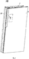
Fig. 1 is a schematically structural view of an overall structure of a refrigerator door of the present invention; -
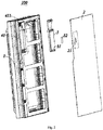
Fig. 2 is a schematically exploded view of the refrigerator door of the present invention; and -
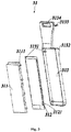
Fig. 3 is a schematically exploded view of a light-emitting component inFig. 2 . - In order to explain the objects, technical solutions and advantages of the present invention more apparently, the present invention is further described in detail below with reference to the accompanying drawings and specific embodiments.
- As shown in
Figs. 1-3 , arefrigerator door 100 of the present invention comprises a frame 1, a glass panel 2 arranged outside the frame 1, a foaming layer (not shown in the Figs.) located between the frame 1 and the glass panel 2, a LOGO display device 3 arranged between the frame 1 and the glass panel 2, and a human body sensing device (not shown in the Figs.). - A transparent
LOGO display area 21 is printed on the glass panel 2, and an area around theLOGO display area 21 is non-transparent. TheLOGO display area 21 corresponds to a LOGO pattern required to be displayed, and of course, may display other patterns, stripes, or the like, which are not limited in the present invention. As an existing printing method such as screen printing will generate an ink layer on the glass panel 2 to form stepped protrusions, in the embodiment, a side of theLOGO display area 21 facing the frame 1 is coated with an optically clear adhesive to enable the surface of theLOGO display area 21 to be flat. In addition, a printing error in the existing printing method is relatively larger, resulting in a relatively fuzzy boundary of theLOGO display area 21. In the embodiment, theLOGO display area 21 is printed by using a multi-layer printing process; a hollowed-out area is arranged on each printing layer; the hollowed-out areas on the multi-layer printing layers form theLOGO display area 21 correspondingly; and an error between the hollowed-out areas of the multi-layer printing layers is controlled to be less than 0.5 mm, so that the boundary of theLOGO display area 21 of the present invention is clear. - The LOGO display device 3 comprises a light-
emitting component 31 and a one-way vision film 32. - The one-
way vision film 32 is arranged between theLOGO display area 21 and the light-emitting component 31, and is directly attached to theLOGO display area 21 or the light-emitting component 31 by using a glue. As theLOGO display area 21 is coated with an optically clear adhesive, the one-way vision film 32 and theLOGO display area 21 can be closely adhered to each other without bubbles, and the light emitted by the light-emittingcomponent 31 will not be refracted due to the bubbles. In the embodiment, the one-way vision film 32 is a mirror-like silver transparent film. When the light-emitting component 31 does not emit light, theLOGO display area 21 displays a mirror-like silver color; and when the light-emitting component 31 emits light, theLOGO display area 21 allows the light to transmit and displays a bright silver color. - The light-
emitting component 31 comprises a light-emittingplate 312, a lightsmoothing cover plate 311 arranged between the light-emittingplate 312 and the one-way vision film 32, and a supportingplate 313 arranged between the light-emittingplate 312 and the frame 1. - The light-emitting
plate 312 is an area light source; and the lightsmoothing cover plate 311 is configured to uniformly disperse the light emitted by the light-emittingplate 312. A lateral side of the lightsmoothing cover plate 311 is provided with aclamping portion 3111; a lateral side of the light-emittingplate 312 is provided with abuckling portion 3121; and theclamping portion 3111 and thebuckling portion 3121 cooperate to fixedly connect the light-emittingplate 312 and the lightsmoothing cover plate 311. - Connecting
holes 3131 are correspondingly formed in the light-emittingplate 312 and the supportingplate 313; and the light-emitting component 31 further comprises a connecting member which passes through the connectingholes 3131 to fixedly connect the light-emittingplate 312 and the supportingplate 313. The supportingplate 313 is configured to support the light-emittingplate 312 and the lightsmoothing cover plate 311. - A
limiting protrusion 3132 is arranged at a side of the supportingplate 313 away from the light-emittingplate 312, and is abutted against the frame 1 or the foaming layer to press the one-way vision film 32, so that the one-way vision film 32 clings to theLOGO display area 21. - An
accommodating space 41 is reserved in the foaming layer to place the LOGO display device 3. In the embodiment, theaccommodating space 41 is provided with anupward opening 411, so that the LOGO display device 3 can be placed into theaccommodating space 41 through the opening 411 downwards. Ahandle area 3134 is protrusively arranged at the top end of the supportingplate 313, and is convenient to hold, so that the LOGO display device 3 can be mounted or replaced conveniently. Meanwhile, afixing hole 3133 is further formed in the top of the supportingplate 313; and the supportingplate 313 and the frame 1 can be fixed together through a bolt and the like. - A human body sensing device is arranged on the
refrigerator door 100, and is electrically connected to the LOGO display device 3. When detecting that someone approaches therefrigerator door 100, the human body sensing device sends a signal to the LOGO display device 3, and the LOGO display device 3 controls the light-emitting component 31 to emit light. - Of course, in other embodiments, other sensing devices may also be arranged to control the light-emitting
component 31 to emit light under certain conditions. Or, a timer may be arranged to control the light-emitting component 31 to emit light during a certain period of time. - A manufacturing method of the
refrigerator door 100 of the present invention comprises the following steps: - providing a frame 1;
- providing a glass panel 2; printing a
LOGO display area 21 on the glass panel 2 by using a multi-layer printing process, wherein a hollowed-out area is arranged on each printing layer, the hollowed-out areas on the multi-layer printing layers form theLOGO display area 21 correspondingly, and an error between the hollowed-out areas of the multi-layer printing layers is controlled to be less than 0.5 mm; - assembling the frame 1 and the glass panel 2 together;
- providing a LOGO display device 3 which comprises a one-
way vision film 32 and a light-emittingcomponent 31; attaching the one-way vision film 32 on theLOGO display area 21, wherein attaching the one-way vision film 32 on theLOGO display area 21 is performed under a negative pressure environment, or before attaching, theLOGO display area 21 is coated with an optically clear adhesive; and - foaming between the glass panel 2 and the frame 1 to form a foaming layer; reserving an
accommodating space 41 at a side of theLOGO display area 21 facing the frame 1, wherein theaccommodating space 41 has anopening 411; and mounting the light-emittingcomponent 31 into theaccommodating space 41 through theopening 411. - Another manufacturing method of the
refrigerator door 100 provided by the present invention comprises the following steps: - providing a frame 1;
- providing a glass panel 2; printing a
LOGO display area 21 on the glass panel 2 by using a multi-layer printing process, wherein a hollowed-out area is arranged on each printing layer, the hollowed-out areas on the multi-layer printing layers form theLOGO display area 21 correspondingly, and an error between the hollowed-out areas of the multi-layer printing layers is controlled to be less than 0.5 mm; - assembling the frame 1 and the glass panel 2 together;
- providing a LOGO display device 3 which comprises a one-
way vision film 32 and a light-emittingcomponent 31; attaching the one-way vision film 32 on the light-emittingcomponent 31; and - foaming between the glass panel 2 and the frame 1 to form a foaming layer; reserving an
accommodating space 41 at a side of theLOGO display area 21 facing the frame 1, wherein theaccommodating space 41 has anopening 411; mounting the light-emittingcomponent 31 with the one-way vision film 32 into theaccommodating space 41 through theopening 411; and enabling the one-way vision film 32 to be fit with theLOGO display area 21. - In the
refrigerator door 100 and the manufacturing method thereof provided by the present invention, the transparentLOGO display area 21 is printed on the glass door body (the glass panel) 2, and the one-way vision film 32 and the light-emittingcomponent 31 are arranged on the side of theLOGO display area 21, so that theLOGO display area 21 exhibits at least two states when the light-emittingcomponent 31 emits or does not emit light. The human body sensing device is arranged on therefrigerator door 100, so that the light-emittingcomponent 31 emits light when a user approaches therefrigerator door 100, thereby improving a human-machine interaction experience. In the manufacturing method of therefrigerator door 100, by improving the printing accuracy and reducing the printing error, a problem of a fuzzy boundary of theLOGO display area 21 in the prior art is solved. By attaching the one-way vision film 32 on theLOGO display area 21 under a negative pressure environment, or before attaching the one-way vision film 32, coating theLOGO display area 21 with the optically clear adhesive, bubbles between the one-way vision film 32 and theLOGO display area 21 are avoided, so that the light emitted by the light-emittingcomponent 31 is prevented from being refracted. - The above embodiments are merely provided for describing the technical solutions of the present invention, but not intended to limit the same. Although the present invention has been described in detail with reference to the preferred embodiments, those skilled in the art will appreciate that the technical solutions of the present invention can be modified or replaced with equivalents, without departing from the spirits and scopes of the technical solutions of the present invention.
Claims (10)
- A refrigerator door, comprising: a frame, a glass panel arranged outside the frame, and a LOGO display device arranged between the frame and the glass panel, wherein a transparent LOGO display area is printed on the glass panel; the LOGO display device comprises a light-emitting component and a one-way vision film; the light-emitting component is arranged at a side of the LOGO display area close to the frame; and the one-way vision film is arranged between the LOGO display area and the light-emitting component.
- The refrigerator door of claim 1, wherein a side of the LOGO display area close to the one-way vision film is coated with an optically clear adhesive to enable the surface of the LOGO display area to be flat.
- The refrigerator door of claim 1, wherein the light-emitting component comprises a light-emitting plate and a light smoothing cover plate arranged between the light-emitting plate and the one-way vision film; a lateral side of the light smoothing cover plate is provided with a clamping portion; a lateral side of the light-emitting plate is provided with a buckling portion; and the clamping portion and the buckling portion cooperate to fixedly connect the light-emitting plate and the light smoothing cover plate.
- The refrigerator door of claim 3, wherein the light-emitting component further comprises a supporting plate; connecting holes are correspondingly formed in the light-emitting plate and the supporting plate; and the light-emitting component further comprises a connecting member which passes through the connecting holes to fixedly connect the light-emitting plate and the supporting plate.
- The refrigerator door of claim 4, wherein a limiting protrusion is arranged at a side of the supporting plate away from the light-emitting plate, and is abutted against the frame to press the one-way vision film, so that the one-way vision film clings to the LOGO display area.
- The refrigerator door of claim 1, wherein a human body sensing device is arranged on the refrigerator door, and is electrically connected to the LOGO display device.
- A method of manufacturing the refrigerator door of any of claims 1-6, the method of manufacturing the refrigerator door comprising the following steps:providing a frame;providing a glass panel; printing a LOGO display area on the glass panel by using a multi-layer printing process, wherein a hollowed-out area is arranged on each printing layer, the hollowed-out areas on the multi-layer printing layers form the LOGO display area correspondingly, and an error between the hollowed-out areas of the multi-layer printing layers is controlled to be less than 0.5 mm;assembling the frame and the glass panel together;providing a LOGO display device which comprises a one-way vision film and a light-emitting component; attaching the one-way vision film on the LOGO display area; andfoaming between the glass panel and the frame to form a foaming layer; reserving an accommodating space at a side of the LOGO display area facing the frame, wherein the accommodating space has an opening; and mounting the light-emitting component into the accommodating space through the opening.
- The method of manufacturing the refrigerator door of claim 7, wherein attaching the one-way vision film on the LOGO display area is performed under a negative pressure environment.
- The method of manufacturing the refrigerator door of claim 7, wherein before attaching the one-way vision film on the LOGO display area, the LOGO display area is coated with an optically clear adhesive.
- A method of manufacturing the refrigerator door of any of claims 1-6, the method of manufacturing the refrigerator door comprising the following steps:providing a frame;providing a glass panel; printing a LOGO display area on the glass panel by using a multi-layer printing process, wherein a hollowed-out area is arranged on each printing layer, the hollowed-out areas on the multi-layer printing layers form the LOGO display area correspondingly, and an error between the hollowed-out areas of the multi-layer printing layers is controlled to be less than 0.5 mm;assembling the frame and the glass panel together;providing a LOGO display device which comprises a one-way vision film and a light-emitting component; attaching the one-way vision film on the light-emitting component; andfoaming between the glass panel and the frame to form a foaming layer; reserving an accommodating space at a side of the LOGO display area facing the frame, wherein the accommodating space has an opening; mounting the light-emitting component with the one-way vision film into the accommodating space through the opening; and enabling the one-way vision film to be fit with the LOGO display area.
Applications Claiming Priority (2)
| Application Number | Priority Date | Filing Date | Title |
|---|---|---|---|
| CN201610702930.0A CN106123462B (en) | 2016-08-22 | 2016-08-22 | Refrigerator door body and production method thereof |
| PCT/CN2016/112819 WO2018036058A1 (en) | 2016-08-22 | 2016-12-29 | Refrigerator door and method of manufacturing same |
Publications (3)
| Publication Number | Publication Date |
|---|---|
| EP3502600A1 true EP3502600A1 (en) | 2019-06-26 |
| EP3502600A4 EP3502600A4 (en) | 2019-09-04 |
| EP3502600B1 EP3502600B1 (en) | 2022-05-11 |
Family
ID=57279124
Family Applications (1)
| Application Number | Title | Priority Date | Filing Date |
|---|---|---|---|
| EP16914078.7A Active EP3502600B1 (en) | 2016-08-22 | 2016-12-29 | Refrigerator door and method of manufacturing same |
Country Status (5)
| Country | Link |
|---|---|
| US (1) | US10753670B2 (en) |
| EP (1) | EP3502600B1 (en) |
| CN (1) | CN106123462B (en) |
| AU (1) | AU2016420395B2 (en) |
| WO (1) | WO2018036058A1 (en) |
Families Citing this family (7)
| Publication number | Priority date | Publication date | Assignee | Title |
|---|---|---|---|---|
| CN106123462B (en) * | 2016-08-22 | 2019-03-12 | 青岛海尔股份有限公司 | Refrigerator door body and production method thereof |
| CN107255388B (en) * | 2017-06-26 | 2019-08-27 | 青岛海尔股份有限公司 | Door body and refrigerator with the door body |
| CN108917285B (en) * | 2018-08-13 | 2023-03-31 | 长虹美菱股份有限公司 | Display module structure of glass door refrigerator |
| KR102265911B1 (en) * | 2019-08-20 | 2021-06-17 | 삼성전자주식회사 | Refrigerator and home appliance |
| CN111664643B (en) * | 2020-06-18 | 2021-11-05 | 长虹美菱股份有限公司 | A display panel mounting structure for refrigerator door body |
| CN112856919A (en) * | 2021-02-25 | 2021-05-28 | 滁州美业机械制造有限公司 | Refrigerator door plate processing method |
| CN115826790A (en) * | 2022-12-08 | 2023-03-21 | 广东顺德意达电子薄膜器件有限公司 | A panel and its production method |
Family Cites Families (23)
| Publication number | Priority date | Publication date | Assignee | Title |
|---|---|---|---|---|
| KR100864661B1 (en) * | 2002-09-19 | 2008-10-23 | 엘지전자 주식회사 | Leakage light blocking device for display for refrigerator |
| WO2007011178A1 (en) * | 2005-07-20 | 2007-01-25 | Lg Electronics Inc. | Refrigerator door and method of manufacture thereof |
| CN100371801C (en) * | 2005-12-08 | 2008-02-27 | 友达光电股份有限公司 | Light-emitting component packaging structure, backlight module using same and liquid crystal display |
| KR20080065096A (en) * | 2007-01-08 | 2008-07-11 | 엘지전자 주식회사 | Refrigerator |
| KR101517230B1 (en) * | 2008-02-21 | 2015-05-04 | 엘지전자 주식회사 | Refrigerator and refrigerator door |
| KR101114320B1 (en) * | 2008-11-05 | 2012-02-14 | 엘지전자 주식회사 | Appliances and Washing Water Treatment Equipment |
| CN102401527A (en) * | 2010-09-10 | 2012-04-04 | 海尔集团公司 | Refrigerator, refrigerator door body and display device |
| KR101190448B1 (en) * | 2010-09-14 | 2012-10-11 | 엘지전자 주식회사 | Refrigerator |
| KR20130052782A (en) * | 2011-11-14 | 2013-05-23 | 엘지전자 주식회사 | Refrigerator |
| CN202373238U (en) * | 2012-05-11 | 2012-08-08 | 中国北车集团大连机车车辆有限公司 | Urban rail vehicle information display |
| KR101990588B1 (en) * | 2013-02-25 | 2019-06-18 | 엘지전자 주식회사 | Refrigerator |
| JP6402353B2 (en) * | 2013-03-29 | 2018-10-10 | パナソニックIpマネジメント株式会社 | Refrigerator and refrigerator system |
| CN103412690A (en) * | 2013-06-05 | 2013-11-27 | 上海瑞霞企业管理咨询有限公司 | Projection-type multi-point capacitance touch screen |
| US9703263B2 (en) * | 2013-07-08 | 2017-07-11 | Douglas Durkee | Floor clock having enhanced infinity mirror |
| CN103474004A (en) * | 2013-09-06 | 2013-12-25 | 乐视致新电子科技(天津)有限公司 | Display nameplate, manufacturing method thereof and display device |
| US9568186B2 (en) * | 2013-09-19 | 2017-02-14 | Lit Coolers, Llc | Container apparatus and method of using same |
| US20150113841A1 (en) * | 2013-10-29 | 2015-04-30 | Whirlpool Corporation | Alphanumeric display assembly |
| CN203731782U (en) * | 2013-11-21 | 2014-07-23 | 博西华电器(江苏)有限公司 | Refrigerator |
| KR101668922B1 (en) * | 2014-12-24 | 2016-10-24 | 엘지전자 주식회사 | Home appliance display assembly and manufacture method thereof |
| EP3147609B1 (en) * | 2015-09-25 | 2023-07-26 | Lg Electronics Inc. | A refrigerator door including an exterior member |
| CN105627676A (en) * | 2016-03-01 | 2016-06-01 | 上海九山电子科技有限公司 | Refrigerator door with semi-transparent liquid crystal light-emitting structure and manufacturing method thereof |
| CN106123462B (en) * | 2016-08-22 | 2019-03-12 | 青岛海尔股份有限公司 | Refrigerator door body and production method thereof |
| CN206056087U (en) * | 2016-08-22 | 2017-03-29 | 青岛海尔股份有限公司 | refrigerator door |
-
2016
- 2016-08-22 CN CN201610702930.0A patent/CN106123462B/en active Active
- 2016-12-29 WO PCT/CN2016/112819 patent/WO2018036058A1/en not_active Ceased
- 2016-12-29 US US16/327,795 patent/US10753670B2/en active Active
- 2016-12-29 EP EP16914078.7A patent/EP3502600B1/en active Active
- 2016-12-29 AU AU2016420395A patent/AU2016420395B2/en active Active
Also Published As
| Publication number | Publication date |
|---|---|
| US10753670B2 (en) | 2020-08-25 |
| US20190234678A1 (en) | 2019-08-01 |
| CN106123462B (en) | 2019-03-12 |
| AU2016420395B2 (en) | 2020-02-20 |
| EP3502600A4 (en) | 2019-09-04 |
| EP3502600B1 (en) | 2022-05-11 |
| WO2018036058A1 (en) | 2018-03-01 |
| AU2016420395A1 (en) | 2019-03-14 |
| NZ750944A (en) | 2020-10-30 |
| CN106123462A (en) | 2016-11-16 |
Similar Documents
| Publication | Publication Date | Title |
|---|---|---|
| US10753670B2 (en) | Refrigerator door and method of manufacturing same | |
| KR100921306B1 (en) | Automobile decoration apparatus for door scuff | |
| US20180067253A1 (en) | Display device | |
| NZ750944B2 (en) | Refrigerator door and method of manufacturing same | |
| KR101647746B1 (en) | Display device and manufacturing method thereof | |
| CN206056087U (en) | refrigerator door | |
| CN216216828U (en) | Real wood touch structure | |
| CN110580106B (en) | Display control panel and assembling method | |
| KR102580488B1 (en) | A curved glass Laminate Pressing Unit | |
| CN212430363U (en) | Mounting device and mounting structure of mirror display equipment | |
| JP2013094202A (en) | Backlight device | |
| JP3136815U (en) | LED nameplate | |
| CN207557608U (en) | A kind of touch-control display module | |
| CN112333406A (en) | Trim structure and TV | |
| JP3165525U (en) | Luminescent display panel | |
| CN216957174U (en) | Electronic component and display device | |
| CN220553262U (en) | Silicon-based OLED micro display screen shading device | |
| KR20150028142A (en) | Display apparatus | |
| CN211138887U (en) | Colored glaze decoration glass picture | |
| JP2000244135A (en) | Thin image display device | |
| CN219872785U (en) | Display device | |
| CN203033577U (en) | Control button device specific for elevator | |
| CN121297337A (en) | Decorative panel components, refrigerator door and refrigerator | |
| KR20200027124A (en) | Assembly structure for display apparatus | |
| CN108540609A (en) | Mobile phone |
Legal Events
| Date | Code | Title | Description |
|---|---|---|---|
| STAA | Information on the status of an ep patent application or granted ep patent |
Free format text: STATUS: THE INTERNATIONAL PUBLICATION HAS BEEN MADE |
|
| PUAI | Public reference made under article 153(3) epc to a published international application that has entered the european phase |
Free format text: ORIGINAL CODE: 0009012 |
|
| STAA | Information on the status of an ep patent application or granted ep patent |
Free format text: STATUS: REQUEST FOR EXAMINATION WAS MADE |
|
| 17P | Request for examination filed |
Effective date: 20190222 |
|
| AK | Designated contracting states |
Kind code of ref document: A1 Designated state(s): AL AT BE BG CH CY CZ DE DK EE ES FI FR GB GR HR HU IE IS IT LI LT LU LV MC MK MT NL NO PL PT RO RS SE SI SK SM TR |
|
| AX | Request for extension of the european patent |
Extension state: BA ME |
|
| A4 | Supplementary search report drawn up and despatched |
Effective date: 20190806 |
|
| RIC1 | Information provided on ipc code assigned before grant |
Ipc: F25D 23/02 20060101AFI20190731BHEP |
|
| DAV | Request for validation of the european patent (deleted) | ||
| DAX | Request for extension of the european patent (deleted) | ||
| STAA | Information on the status of an ep patent application or granted ep patent |
Free format text: STATUS: EXAMINATION IS IN PROGRESS |
|
| 17Q | First examination report despatched |
Effective date: 20200603 |
|
| GRAP | Despatch of communication of intention to grant a patent |
Free format text: ORIGINAL CODE: EPIDOSNIGR1 |
|
| STAA | Information on the status of an ep patent application or granted ep patent |
Free format text: STATUS: GRANT OF PATENT IS INTENDED |
|
| INTG | Intention to grant announced |
Effective date: 20211208 |
|
| GRAS | Grant fee paid |
Free format text: ORIGINAL CODE: EPIDOSNIGR3 |
|
| GRAA | (expected) grant |
Free format text: ORIGINAL CODE: 0009210 |
|
| STAA | Information on the status of an ep patent application or granted ep patent |
Free format text: STATUS: THE PATENT HAS BEEN GRANTED |
|
| AK | Designated contracting states |
Kind code of ref document: B1 Designated state(s): AL AT BE BG CH CY CZ DE DK EE ES FI FR GB GR HR HU IE IS IT LI LT LU LV MC MK MT NL NO PL PT RO RS SE SI SK SM TR |
|
| REG | Reference to a national code |
Ref country code: GB Ref legal event code: FG4D |
|
| REG | Reference to a national code |
Ref country code: CH Ref legal event code: EP |
|
| REG | Reference to a national code |
Ref country code: AT Ref legal event code: REF Ref document number: 1491729 Country of ref document: AT Kind code of ref document: T Effective date: 20220515 |
|
| REG | Reference to a national code |
Ref country code: DE Ref legal event code: R096 Ref document number: 602016072175 Country of ref document: DE |
|
| REG | Reference to a national code |
Ref country code: IE Ref legal event code: FG4D |
|
| REG | Reference to a national code |
Ref country code: LT Ref legal event code: MG9D |
|
| REG | Reference to a national code |
Ref country code: NL Ref legal event code: MP Effective date: 20220511 |
|
| REG | Reference to a national code |
Ref country code: AT Ref legal event code: MK05 Ref document number: 1491729 Country of ref document: AT Kind code of ref document: T Effective date: 20220511 |
|
| PG25 | Lapsed in a contracting state [announced via postgrant information from national office to epo] |
Ref country code: SE Free format text: LAPSE BECAUSE OF FAILURE TO SUBMIT A TRANSLATION OF THE DESCRIPTION OR TO PAY THE FEE WITHIN THE PRESCRIBED TIME-LIMIT Effective date: 20220511 Ref country code: PT Free format text: LAPSE BECAUSE OF FAILURE TO SUBMIT A TRANSLATION OF THE DESCRIPTION OR TO PAY THE FEE WITHIN THE PRESCRIBED TIME-LIMIT Effective date: 20220912 Ref country code: NO Free format text: LAPSE BECAUSE OF FAILURE TO SUBMIT A TRANSLATION OF THE DESCRIPTION OR TO PAY THE FEE WITHIN THE PRESCRIBED TIME-LIMIT Effective date: 20220811 Ref country code: NL Free format text: LAPSE BECAUSE OF FAILURE TO SUBMIT A TRANSLATION OF THE DESCRIPTION OR TO PAY THE FEE WITHIN THE PRESCRIBED TIME-LIMIT Effective date: 20220511 Ref country code: LT Free format text: LAPSE BECAUSE OF FAILURE TO SUBMIT A TRANSLATION OF THE DESCRIPTION OR TO PAY THE FEE WITHIN THE PRESCRIBED TIME-LIMIT Effective date: 20220511 Ref country code: HR Free format text: LAPSE BECAUSE OF FAILURE TO SUBMIT A TRANSLATION OF THE DESCRIPTION OR TO PAY THE FEE WITHIN THE PRESCRIBED TIME-LIMIT Effective date: 20220511 Ref country code: GR Free format text: LAPSE BECAUSE OF FAILURE TO SUBMIT A TRANSLATION OF THE DESCRIPTION OR TO PAY THE FEE WITHIN THE PRESCRIBED TIME-LIMIT Effective date: 20220812 Ref country code: FI Free format text: LAPSE BECAUSE OF FAILURE TO SUBMIT A TRANSLATION OF THE DESCRIPTION OR TO PAY THE FEE WITHIN THE PRESCRIBED TIME-LIMIT Effective date: 20220511 Ref country code: ES Free format text: LAPSE BECAUSE OF FAILURE TO SUBMIT A TRANSLATION OF THE DESCRIPTION OR TO PAY THE FEE WITHIN THE PRESCRIBED TIME-LIMIT Effective date: 20220511 Ref country code: BG Free format text: LAPSE BECAUSE OF FAILURE TO SUBMIT A TRANSLATION OF THE DESCRIPTION OR TO PAY THE FEE WITHIN THE PRESCRIBED TIME-LIMIT Effective date: 20220811 Ref country code: AT Free format text: LAPSE BECAUSE OF FAILURE TO SUBMIT A TRANSLATION OF THE DESCRIPTION OR TO PAY THE FEE WITHIN THE PRESCRIBED TIME-LIMIT Effective date: 20220511 |
|
| PG25 | Lapsed in a contracting state [announced via postgrant information from national office to epo] |
Ref country code: RS Free format text: LAPSE BECAUSE OF FAILURE TO SUBMIT A TRANSLATION OF THE DESCRIPTION OR TO PAY THE FEE WITHIN THE PRESCRIBED TIME-LIMIT Effective date: 20220511 Ref country code: PL Free format text: LAPSE BECAUSE OF FAILURE TO SUBMIT A TRANSLATION OF THE DESCRIPTION OR TO PAY THE FEE WITHIN THE PRESCRIBED TIME-LIMIT Effective date: 20220511 Ref country code: LV Free format text: LAPSE BECAUSE OF FAILURE TO SUBMIT A TRANSLATION OF THE DESCRIPTION OR TO PAY THE FEE WITHIN THE PRESCRIBED TIME-LIMIT Effective date: 20220511 Ref country code: IS Free format text: LAPSE BECAUSE OF FAILURE TO SUBMIT A TRANSLATION OF THE DESCRIPTION OR TO PAY THE FEE WITHIN THE PRESCRIBED TIME-LIMIT Effective date: 20220911 |
|
| PG25 | Lapsed in a contracting state [announced via postgrant information from national office to epo] |
Ref country code: SM Free format text: LAPSE BECAUSE OF FAILURE TO SUBMIT A TRANSLATION OF THE DESCRIPTION OR TO PAY THE FEE WITHIN THE PRESCRIBED TIME-LIMIT Effective date: 20220511 Ref country code: SK Free format text: LAPSE BECAUSE OF FAILURE TO SUBMIT A TRANSLATION OF THE DESCRIPTION OR TO PAY THE FEE WITHIN THE PRESCRIBED TIME-LIMIT Effective date: 20220511 Ref country code: RO Free format text: LAPSE BECAUSE OF FAILURE TO SUBMIT A TRANSLATION OF THE DESCRIPTION OR TO PAY THE FEE WITHIN THE PRESCRIBED TIME-LIMIT Effective date: 20220511 Ref country code: EE Free format text: LAPSE BECAUSE OF FAILURE TO SUBMIT A TRANSLATION OF THE DESCRIPTION OR TO PAY THE FEE WITHIN THE PRESCRIBED TIME-LIMIT Effective date: 20220511 Ref country code: DK Free format text: LAPSE BECAUSE OF FAILURE TO SUBMIT A TRANSLATION OF THE DESCRIPTION OR TO PAY THE FEE WITHIN THE PRESCRIBED TIME-LIMIT Effective date: 20220511 Ref country code: CZ Free format text: LAPSE BECAUSE OF FAILURE TO SUBMIT A TRANSLATION OF THE DESCRIPTION OR TO PAY THE FEE WITHIN THE PRESCRIBED TIME-LIMIT Effective date: 20220511 |
|
| REG | Reference to a national code |
Ref country code: DE Ref legal event code: R097 Ref document number: 602016072175 Country of ref document: DE |
|
| PLBE | No opposition filed within time limit |
Free format text: ORIGINAL CODE: 0009261 |
|
| STAA | Information on the status of an ep patent application or granted ep patent |
Free format text: STATUS: NO OPPOSITION FILED WITHIN TIME LIMIT |
|
| PG25 | Lapsed in a contracting state [announced via postgrant information from national office to epo] |
Ref country code: AL Free format text: LAPSE BECAUSE OF FAILURE TO SUBMIT A TRANSLATION OF THE DESCRIPTION OR TO PAY THE FEE WITHIN THE PRESCRIBED TIME-LIMIT Effective date: 20220511 |
|
| 26N | No opposition filed |
Effective date: 20230214 |
|
| PG25 | Lapsed in a contracting state [announced via postgrant information from national office to epo] |
Ref country code: SI Free format text: LAPSE BECAUSE OF FAILURE TO SUBMIT A TRANSLATION OF THE DESCRIPTION OR TO PAY THE FEE WITHIN THE PRESCRIBED TIME-LIMIT Effective date: 20220511 |
|
| REG | Reference to a national code |
Ref country code: CH Ref legal event code: PL |
|
| REG | Reference to a national code |
Ref country code: BE Ref legal event code: MM Effective date: 20221231 |
|
| PG25 | Lapsed in a contracting state [announced via postgrant information from national office to epo] |
Ref country code: LU Free format text: LAPSE BECAUSE OF NON-PAYMENT OF DUE FEES Effective date: 20221229 |
|
| PG25 | Lapsed in a contracting state [announced via postgrant information from national office to epo] |
Ref country code: LI Free format text: LAPSE BECAUSE OF NON-PAYMENT OF DUE FEES Effective date: 20221231 Ref country code: IE Free format text: LAPSE BECAUSE OF NON-PAYMENT OF DUE FEES Effective date: 20221229 Ref country code: CH Free format text: LAPSE BECAUSE OF NON-PAYMENT OF DUE FEES Effective date: 20221231 |
|
| PG25 | Lapsed in a contracting state [announced via postgrant information from national office to epo] |
Ref country code: BE Free format text: LAPSE BECAUSE OF NON-PAYMENT OF DUE FEES Effective date: 20221231 |
|
| PG25 | Lapsed in a contracting state [announced via postgrant information from national office to epo] |
Ref country code: HU Free format text: LAPSE BECAUSE OF FAILURE TO SUBMIT A TRANSLATION OF THE DESCRIPTION OR TO PAY THE FEE WITHIN THE PRESCRIBED TIME-LIMIT; INVALID AB INITIO Effective date: 20161229 |
|
| PG25 | Lapsed in a contracting state [announced via postgrant information from national office to epo] |
Ref country code: CY Free format text: LAPSE BECAUSE OF FAILURE TO SUBMIT A TRANSLATION OF THE DESCRIPTION OR TO PAY THE FEE WITHIN THE PRESCRIBED TIME-LIMIT Effective date: 20220511 |
|
| PG25 | Lapsed in a contracting state [announced via postgrant information from national office to epo] |
Ref country code: MK Free format text: LAPSE BECAUSE OF FAILURE TO SUBMIT A TRANSLATION OF THE DESCRIPTION OR TO PAY THE FEE WITHIN THE PRESCRIBED TIME-LIMIT Effective date: 20220511 |
|
| PG25 | Lapsed in a contracting state [announced via postgrant information from national office to epo] |
Ref country code: MC Free format text: LAPSE BECAUSE OF FAILURE TO SUBMIT A TRANSLATION OF THE DESCRIPTION OR TO PAY THE FEE WITHIN THE PRESCRIBED TIME-LIMIT Effective date: 20220511 |
|
| PG25 | Lapsed in a contracting state [announced via postgrant information from national office to epo] |
Ref country code: TR Free format text: LAPSE BECAUSE OF FAILURE TO SUBMIT A TRANSLATION OF THE DESCRIPTION OR TO PAY THE FEE WITHIN THE PRESCRIBED TIME-LIMIT Effective date: 20220511 Ref country code: MC Free format text: LAPSE BECAUSE OF FAILURE TO SUBMIT A TRANSLATION OF THE DESCRIPTION OR TO PAY THE FEE WITHIN THE PRESCRIBED TIME-LIMIT Effective date: 20220511 |
|
| PG25 | Lapsed in a contracting state [announced via postgrant information from national office to epo] |
Ref country code: MT Free format text: LAPSE BECAUSE OF FAILURE TO SUBMIT A TRANSLATION OF THE DESCRIPTION OR TO PAY THE FEE WITHIN THE PRESCRIBED TIME-LIMIT Effective date: 20220511 |
|
| PG25 | Lapsed in a contracting state [announced via postgrant information from national office to epo] |
Ref country code: BG Free format text: LAPSE BECAUSE OF FAILURE TO SUBMIT A TRANSLATION OF THE DESCRIPTION OR TO PAY THE FEE WITHIN THE PRESCRIBED TIME-LIMIT Effective date: 20220511 |
|
| PG25 | Lapsed in a contracting state [announced via postgrant information from national office to epo] |
Ref country code: BG Free format text: LAPSE BECAUSE OF FAILURE TO SUBMIT A TRANSLATION OF THE DESCRIPTION OR TO PAY THE FEE WITHIN THE PRESCRIBED TIME-LIMIT Effective date: 20220511 |
|
| PGFP | Annual fee paid to national office [announced via postgrant information from national office to epo] |
Ref country code: GB Payment date: 20251229 Year of fee payment: 10 |
|
| PGFP | Annual fee paid to national office [announced via postgrant information from national office to epo] |
Ref country code: IT Payment date: 20251210 Year of fee payment: 10 |
|
| PGFP | Annual fee paid to national office [announced via postgrant information from national office to epo] |
Ref country code: FR Payment date: 20251230 Year of fee payment: 10 |
|
| PGFP | Annual fee paid to national office [announced via postgrant information from national office to epo] |
Ref country code: DE Payment date: 20251231 Year of fee payment: 10 |