EP3502590A1 - Apparatus and method for dual refrigerant tank refill - Google Patents
Apparatus and method for dual refrigerant tank refill Download PDFInfo
- Publication number
- EP3502590A1 EP3502590A1 EP18214750.4A EP18214750A EP3502590A1 EP 3502590 A1 EP3502590 A1 EP 3502590A1 EP 18214750 A EP18214750 A EP 18214750A EP 3502590 A1 EP3502590 A1 EP 3502590A1
- Authority
- EP
- European Patent Office
- Prior art keywords
- refrigerant
- tank
- delivery system
- hose
- resupply
- Prior art date
- Legal status (The legal status is an assumption and is not a legal conclusion. Google has not performed a legal analysis and makes no representation as to the accuracy of the status listed.)
- Pending
Links
Images





Classifications
-
- F—MECHANICAL ENGINEERING; LIGHTING; HEATING; WEAPONS; BLASTING
- F25—REFRIGERATION OR COOLING; COMBINED HEATING AND REFRIGERATION SYSTEMS; HEAT PUMP SYSTEMS; MANUFACTURE OR STORAGE OF ICE; LIQUEFACTION SOLIDIFICATION OF GASES
- F25B—REFRIGERATION MACHINES, PLANTS OR SYSTEMS; COMBINED HEATING AND REFRIGERATION SYSTEMS; HEAT PUMP SYSTEMS
- F25B45/00—Arrangements for charging or discharging refrigerant
-
- F—MECHANICAL ENGINEERING; LIGHTING; HEATING; WEAPONS; BLASTING
- F25—REFRIGERATION OR COOLING; COMBINED HEATING AND REFRIGERATION SYSTEMS; HEAT PUMP SYSTEMS; MANUFACTURE OR STORAGE OF ICE; LIQUEFACTION SOLIDIFICATION OF GASES
- F25B—REFRIGERATION MACHINES, PLANTS OR SYSTEMS; COMBINED HEATING AND REFRIGERATION SYSTEMS; HEAT PUMP SYSTEMS
- F25B2345/00—Details for charging or discharging refrigerants; Service stations therefor
- F25B2345/001—Charging refrigerant to a cycle
-
- F—MECHANICAL ENGINEERING; LIGHTING; HEATING; WEAPONS; BLASTING
- F25—REFRIGERATION OR COOLING; COMBINED HEATING AND REFRIGERATION SYSTEMS; HEAT PUMP SYSTEMS; MANUFACTURE OR STORAGE OF ICE; LIQUEFACTION SOLIDIFICATION OF GASES
- F25B—REFRIGERATION MACHINES, PLANTS OR SYSTEMS; COMBINED HEATING AND REFRIGERATION SYSTEMS; HEAT PUMP SYSTEMS
- F25B2345/00—Details for charging or discharging refrigerants; Service stations therefor
- F25B2345/002—Collecting refrigerant from a cycle
-
- F—MECHANICAL ENGINEERING; LIGHTING; HEATING; WEAPONS; BLASTING
- F25—REFRIGERATION OR COOLING; COMBINED HEATING AND REFRIGERATION SYSTEMS; HEAT PUMP SYSTEMS; MANUFACTURE OR STORAGE OF ICE; LIQUEFACTION SOLIDIFICATION OF GASES
- F25B—REFRIGERATION MACHINES, PLANTS OR SYSTEMS; COMBINED HEATING AND REFRIGERATION SYSTEMS; HEAT PUMP SYSTEMS
- F25B2345/00—Details for charging or discharging refrigerants; Service stations therefor
- F25B2345/004—Details for charging or discharging refrigerants; Service stations therefor with several tanks to collect or charge a cycle
-
- F—MECHANICAL ENGINEERING; LIGHTING; HEATING; WEAPONS; BLASTING
- F25—REFRIGERATION OR COOLING; COMBINED HEATING AND REFRIGERATION SYSTEMS; HEAT PUMP SYSTEMS; MANUFACTURE OR STORAGE OF ICE; LIQUEFACTION SOLIDIFICATION OF GASES
- F25B—REFRIGERATION MACHINES, PLANTS OR SYSTEMS; COMBINED HEATING AND REFRIGERATION SYSTEMS; HEAT PUMP SYSTEMS
- F25B2345/00—Details for charging or discharging refrigerants; Service stations therefor
- F25B2345/005—Service stations therefor
- F25B2345/0052—Service stations therefor having wheels
-
- F—MECHANICAL ENGINEERING; LIGHTING; HEATING; WEAPONS; BLASTING
- F25—REFRIGERATION OR COOLING; COMBINED HEATING AND REFRIGERATION SYSTEMS; HEAT PUMP SYSTEMS; MANUFACTURE OR STORAGE OF ICE; LIQUEFACTION SOLIDIFICATION OF GASES
- F25B—REFRIGERATION MACHINES, PLANTS OR SYSTEMS; COMBINED HEATING AND REFRIGERATION SYSTEMS; HEAT PUMP SYSTEMS
- F25B2400/00—Component parts or details not otherwise provided for in this subclass
- F25B2400/12—Inflammable refrigerants
- F25B2400/121—Inflammable refrigerants using R1234
Definitions
- refrigerant such as air conditioning systems, for example.
- the R-134a refrigerant is being phased out and for newer vehicle models, the refrigerant 2,3,3,3-tetrafluoroprene - R-1234yf is coming into more widespread use.
- refrigerant delivery and recovery units can be used.
- Refrigerant delivery and recovery units can be equipped with a storage tank for storing refrigerant.
- a refrigerant delivery and recovery unit having two sources (e.g., two tanks) of refrigerant (e.g., R-134a and R-1234yf) to accommodate vehicles having different refrigerant requirements.
- refrigerant delivery and recovery unit having the capability of refilling or replenishing either refrigerant tank when the refrigerant runs low or is depleted in either of the refrigerant tanks.
- a refrigerant delivery and recovery unit that advantageously includes two or more separate tanks for storing distinct types of refrigerant, such as R-134a and R-1234yf refrigerant.
- a refrigerant delivery and recovery unit is provided having a dual tank configuration with a first tank for storing a first type of refrigerant (e.g. R-134a) and a second tank for storing a second type of refrigerant (e.g. R-1234yf).
- the dual tank configuration provides that the refrigerant delivery and recovery unit has a supply of two distinct types of refrigerant to deliver to a vehicle requiring either the first type of refrigerant (e.g.
- the refrigerant delivery and recovery unit advantageously provides for an additional refrigerant resupply tank that may be used to supply either the first or second tank with the appropriate refrigerant.
- the refrigerant delivery and recovery unit further includes safeguards for insuring that only the proper type of refrigerant is supplied to the first or second tank during the process of resupplying the first or second tank with refrigerant.
- the present disclosure further provides for a method of resupplying a refrigerant delivery and recovery unit having a first tank containing a first type of refrigerant (e.g. R-134a) and a second tank containing a second type of refrigerant (e.g. R-1234yf) from a refrigerant resupply tank.
- the method further includes safeguards for insuring that only the proper type of refrigerant (e.g. R-134a or R-1234yf) is resupplied to the first or second tank during the process of resupplying the first or second tank with refrigerant
- a refrigerant delivery and recovery unit having a refrigerant tank housing, a first storage tank positioned within the refrigerant tank housing, a second storage tank positioned within the refrigerant tank housing, a refrigerant delivery system positioned within the refrigerant tank housing, the refrigerant delivery system adapted to supply a first refrigerant to the first storage tank and a second refrigerant to the second storage tank, a tank recess on the housing for receiving a refrigerant resupply tank therein, a first refrigerant hose having a first fitting adapted for connection to a first refrigerant resupply tank, a second refrigerant hose having a first fitting adapted for connection to a second refrigerant resupply tank, wherein the first refrigerant hose is adapted for connection to the refrigerant delivery system, wherein the second refrigerant hose is adapted for connection to the refrigerant delivery system, wherein the first refrigerant
- an example embodiment takes the form of a method.
- the method includes steps of (i) providing a refrigerant supply unit having a refrigerant tank housing having a first storage tank positioned within the refrigerant tank housing and a second storage tank positioned within the refrigerant tank housing, a refrigerant delivery system positioned within the refrigerant tank housing, the refrigerant delivery system adapted to supply a first refrigerant to the first storage tank and a second refrigerant to the second storage tank, a tank recess on the housing for receiving a refrigerant resupply tank therein, a first refrigerant hose having a first fitting adapted for connection to a first refrigerant resupply tank, a second refrigerant hose having a first fitting adapted for connection to a second refrigerant resupply tank, wherein the first refrigerant hose is adapted for connection to the refrigerant delivery system, wherein the second refrigerant hose
- the method may further include the steps of (v) disconnecting the first refrigerant resupply tank from the first refrigerant hose and removing the first refrigerant resupply tank from the tank recess; (vi) securing a second refrigerant resupply tank containing a second refrigerant within the tank recess; (vii) attaching the first fitting of the second refrigerant hose to the second refrigerant resupply tank, , wherein the second refrigerant hose is connected to the refrigerant delivery system and the refrigerant delivery system is connected to the second storage tank; and (viii) supplying the second refrigerant from the second refrigerant resupply tank through the second refrigerant hose and the refrigerant delivery system to the second storage tank.
- a means for resupplying first and second storage tanks containing different types of refrigerant with the proper refrigerant during a process of resupplying the first or second tank with refrigerant is provided.
- the articles “a,” “an,” and “the” are used to introduce elements and/or functions of the example embodiments.
- the intent of using those articles is that there is one or more of the introduced elements and/or functions.
- the intent of using the term “and/or” within a list of at least two elements or functions and the intent of using the terms "at least one of' and “one or more of' immediately preceding a list of at least two elements or functions is to cover each embodiment including a listed element or function independently and each embodiment comprising a combination of the listed elements or functions.
- an embodiment described as comprising "A, B, and/or C,” or “at least one of A, B, and C,” or “one or more of A, B, and C” is intended to cover each of the following possible embodiments: (i) an embodiment comprising A, but not B and C, (ii) an embodiment comprising B, but not A and C, (iii) an embodiment comprising C, but not A and B, (iv) an embodiment comprising A and B, but not C, (v) an embodiment comprising A and C, but not B, (v) an embodiment comprising B and C, but not A, and (vi) an embodiment comprising A, B, and C.
- the embodiments can comprise one A or multiple A.
- the embodiments can comprise one B or multiple B.
- the embodiments comprising element or function C can comprise one C or multiple C.
- the use of ordinal numbers such as “first,” “second,” “third” and so on is to distinguish respective elements rather than to denote a particular order of those elements unless the context of using those terms explicitly indicates otherwise.
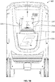
- FIG 1A is a perspective rear view of refrigerant delivery and recovery unit 100 having a refrigerant resupply tank 200 positioned within tank recess 230 and Figure 1B is a rear view of delivery and recovery unit 100.
- a tank guard 240 extends across tank recess 230 to partially enclose refrigerant resupply tank 200.
- a first refrigerant hose 210 extends into tank recess 230 and may be connected to a first fitting on refrigerant resupply tank 200.
- First refrigerant hose 210 also extends into refrigerant delivery and recovery unit 100 where it may be connected to a refrigerant delivery system 300 (shown in Figures 6 and7) and in turn to a first refrigerant tank 350 (shown in Figure 6 ) adapted to store a supply of a first type of refrigerant such as R-134a.
- a second refrigerant hose 220 also extends into tank recess 230 and may be connected to a second fitting on a different refrigerant resupply tank 200.
- Second refrigerant hose 220 also extends into refrigerant delivery and recovery unit 100 where it may be connected to the refrigerant delivery system 300 (shown in Figures 6 and 7 ) and in turn to a second refrigerant tank 360 (shown in Figure 6 ) adapted to store a supply of a second type of refrigerant such as R-1234yf.
- FIG 2A is a close up perspective rear view of refrigerant delivery and recovery unit 100 shown in Figures 1A and 1B , with tank guard 240 removed and Figure 2B is a rear view of refrigerant delivery and recovery unit 100 shown in Figure 2A .
- Refrigerant resupply tank 200 is shown positioned within tank recess 230 and rests atop tank base 250.
- a tank strap 260 is positioned across tank recess 230 to secure refrigerant resupply tank 200 in tank recess 230.
- Refrigerant resupply tank 200 may contain a first type of refrigerant, such as R-134a, and may be used to resupply first refrigerant tank 350 (shown in Figure 6 ) with the first type of refrigerant (e.g. R-134a) through refrigerant hose 210.
- first type of refrigerant e.g. R-134a
- second type of refrigerant such as R-1234yf
- the refrigerant resupply tank 200 in tank recess 230 may be swapped out for a different refrigerant resupply tank containing a second type of refrigerant (e.g. R-1234yf).
- the refrigerant resupply tank 200 may be used to resupply the second refrigerant tank 360 (shown in Figure 6 ) through second refrigerant hose 220.
- the second type of refrigerant e.g. R-1234yf
- Refrigerant hoses 210 and 220 may be flexible rubber hoses that may be manipulated to allow for fittings 212 and 224 (shown most clearly in Figure 4 ) on the ends of refrigerant hoses 210 and 220 to be connected to a corresponding fitting on a refrigerant resupply tank 200.
- refrigerant resupply tank 200 is shown in Figures A-2B in an upright position, although it is possible for refrigerant resupply tank 200 to be rotated to an "upside down" position within tank recess 230.
- refrigerant hoses 210 and 220 are flexible to allow for the respective fitting 212 or 222 to be secured to a corresponding fitting on the refrigerant resupply tank 200.
- refrigerant delivery and recovery unit 100 advantageously includes two separate tanks of refrigerant, i.e., a first refrigerant tank 350 containing a first type of refrigerant (R-134a) and a second refrigerant tank 360 containing a second type of refrigerant (R-1234yf) so that vehicles requiring either type of refrigerant (R-134a or R-1234yf) may be resupplied by refrigerant delivery and recovery unit 100.
- a first refrigerant tank 350 containing a first type of refrigerant (R-134a)
- a second refrigerant tank 360 containing a second type of refrigerant (R-1234yf)
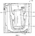
- FIG 3 is a close up perspective rear view of delivery and recovery unit 100 shown in Figures 1A-2B , with tank guard 240 and refrigerant resupply tank 200 removed.
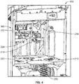
- Figure 4 is a close up perspective rear view of refrigerant delivery and recovery unit 100 shown in Figures 1A-3 with portions removed to show an inside view.
- a tank base 250 is shown at the bottom or tank recess 230, and is used as a base for refrigerant resupply tank 200.
- First refrigerant hose 210 extends downwardly into tank recess 230 where it may be attached to refrigerant resupply tank 200 (shown in Figures 1A-2B ) when it is positioned within tank recess 230.
- First refrigerant hose 210 includes a first fitting 212 that is adapted to be secured to a corresponding first fitting on refrigerant resupply tank 200.
- Second refrigerant hose 220 also extends downwardly into tank recess 230 where it may be attached to a different refrigerant resupply tank 200 when it is positioned within tank recess 230.
- Second refrigerant hose 220 includes a second fitting 222 (shown in Figure 4 ) that is adapted to be secured to a corresponding second fitting on a refrigerant resupply tank 200 containing the second type of refrigerant (e.g. R-1234yf).
- the second type of refrigerant e.g. R-1234yf
- the refrigerant delivery and recovery unit 100 includes a number of safeguards.
- the refrigerant resupply tank 200 is adapted to store the first type of refrigerant (e.g. R-134a), and it is desired to resupply or refill the first refrigerant tank 350 containing the first type of refrigerant with the first type of refrigerant (e.g.
- first refrigerant hose 210 that extends to the first refrigerant tank 350 has a fitting 212 that is configured to attach to a refrigerant resupply tank 200 containing the first type of refrigerant (e.g. R-134a). Fitting 212 is configured so that it is unable to be attached to a fitting on the refrigerant resupply tank 200 containing a second type of refrigerant (e.g. R-1234yf). As shown in Figure 4 , first refrigerant hose 210 also includes a second fitting 214 that is attached to refrigerant delivery system 300 to corresponding fitting on the refrigerant delivery system 300 that is adapted to supply a first type of refrigerant (e.g.
- Fitting 214 is also configured such that it may attach to the corresponding fitting on refrigerant delivery system 300 that supplies the first type of refrigerant (e.g. R-134a) to the first refrigerant tank 350.
- refrigerant hose 220 that extends to the second refrigerant tank 360 has a fitting 222 that is configured to attach to a refrigerant resupply tank 200 containing the second type of refrigerant (e.g. R-1234yf).
- Fitting 222 is configured so that it is unable to be attached to a fitting on the refrigerant resupply tank 200 containing a first type of refrigerant (e.g. R-134a).
- second refrigerant hose 220 also includes a second fitting 224 that is attached to refrigerant delivery system 300 to a corresponding fitting on the refrigerant delivery system 300 that is adapted to supply a second type of refrigerant (e.g. R-1234yf) to the second refrigerant tank 360.
- Fitting 224 is also configured such that it may attach to the corresponding fitting on refrigerant delivery system 300 that supplies the second type of refrigerant (e.g. R-1234yf) to the second refrigerant tank 360.
- fitting 212 of first refrigerant hose 210 may have left-handed threads that attach to a corresponding left-handed threaded fitting on a refrigerant resupply tank 200 containing a first type of refrigerant (e.g. R-134a), and fitting 214 may have left-handed threads that attach to a corresponding left-handed threaded fitting on refrigerant delivery system 300 that leads to the first refrigerant tank 350 containing the first type of refrigerant (e.g. R-134a).
- a first type of refrigerant e.g. R-134a
- fitting 222 of second refrigerant hose 220 may have right-handed threads that attach to a corresponding right-handed threaded fitting on a refrigerant resupply tank 200 containing a second type of refrigerant (e.g. R-1234yf) and fitting 224 may have right-handed threads that attach to a corresponding right-handed threaded fitting on refrigerant delivery system 300 that leads to the second refrigerant tank 360 containing the second type of refrigerant (e.g. R-1234yf).
- a second type of refrigerant e.g. R-1234yf
- first refrigerant hose 210 to connect to a refrigerant resupply tank 200 containing a first type of refrigerant (e.g.. R-134a) and to connect to a fitting on refrigerant delivery system 300 that leads to the first refrigerant tank 350 containing the first refrigerant (e.g. R-134a), provides a safeguard insuring that only the first type of refrigerant (e.g. R-134a) is supplied from a refrigerant resupply tank 200 to first refrigerant tank 350.
- first type of refrigerant e.g. R-134a
- the use of right-handed fittings for the second refrigerant hose 220 to connect to a refrigerant resupply tank 200 containing a second type of refrigerant (e.g.. R-1234yf) and to connect to a fitting on refrigerant delivery system 300 that leads to the second refrigerant tank 360 containing the second refrigerant (e.g. R-1234yf), provides another safeguard insuring that only the second type of refrigerant (e.g. R-1234yf) is supplied from a refrigerant resupply tank 200 to second refrigerant tank 360.
- FIG. 5 is a cross-sectional right side view of refrigerant delivery and recovery unit 100 shown in Figures 1A-4 .
- First refrigerant tank 350 is shown next to refrigerant delivery system 300.
- Tank recess 230 is shown without a refrigerant resupply tank positioned therein.
- First refrigerant hose 210 is shown having a first end having a fitting 212 extending into tank recess 230.
- a second end of first refrigerant hose 210 is shown having a fitting 214 attached to refrigerant delivery system 300 which provides a resupply of a first type of refrigerant (e.g. R-134a) to first refrigerant tank 350.
- a first type of refrigerant e.g. R-134a
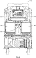
- FIG 6 is a cross-sectional rear view of refrigerant delivery and recovery unit 100 shown in Figures 1A-5 .
- First and second refrigerant tanks 350, 360 are shown positioned within refrigerant delivery and recovery unit 100.
- first refrigerant tank 350 contains a first type of refrigerant (e.g. R-134a) and second refrigerant tank 360 contains a second type of refrigerant (e.g. R-1234yf).
- a refrigerant resupply tank 200 that contains the first type of refrigerant (e.g.
- R-134a is placed within tank recess 230 (shown in Figure 1A-2B ).
- First refrigerant hose 210 is used to transfer the first type of refrigerant (e.g. R-134a) to refrigerant delivery system 300 and on to first refrigerant tank 350, thereby refilling first refrigerant tank 350 with the first type of refrigerant.
- first type of refrigerant e.g. R-134a
- Second refrigerant tank 360 contains a second type of refrigerant (e.g. R-1234yf).
- the refrigerant resupply tank 200 used to resupply the first refrigerant tank 350 is unhooked from first refrigerant hose 210 and removed from the tank recess 230.
- a refrigerant resupply tank 200 that contains the second type of refrigerant (e.g. R-1234yf) is placed within tank recess 230 (as shown in Figure 1A-2B ).
- Second refrigerant hose 220 is used to transfer the second type of refrigerant (e.g. R-1234yf) to refrigerant delivery system 300 and on to second refrigerant tank 360, thereby refilling second refrigerant tank 360 with the second type of refrigerant.
- second type of refrigerant e.g. R-1234yf
- FIG 7 is a schematic representation of the refrigerant delivery system 300 used in delivery and recovery unit 100 shown in Figures 1A-6 .
- a refrigerant resupply tank 200 (shown in Figures 1A-2B ) containing first refrigerant R-134a is positioned in tank recess 230.
- Fitting 212 of first refrigerant hose 210 is attached to a corresponding fitting on refrigerant resupply tank 200.
- Fitting 214 of first refrigerant hose 210 is secured to corresponding fitting 312 on refrigerant delivery system 300 shown in Figure 7 .
- First refrigerant R-134a from refrigerant resupply tank 200 travels through first refrigerant hose 210 and through fitting 312 on refrigerant delivery system 300.
- the first refrigerant R-134a then travels through line 340 to oil separator 330, and then through line 332 to gas identifier 370.
- Gas identifier 370 chemically tests the refrigerant to verify that the refrigerant is the proper refrigerant to travel onward to first refrigerant tank 350.
- first refrigerant R-134a is identified as such by gas identifier 370, the supply of first refrigerant R-134a that enters oil separator 330 through line 340 is allowed to continue outwardly from oil separator 330 through line 342 to condenser 382 and then travels through line 344 to first refrigerant tank 350 to replenish the supply of first refrigerant R-134a in first refrigerant tank 350.
- a refrigerant resupply tank 200 (shown in Figures 1A-2B ) containing second refrigerant R-1234yf is positioned in tank recess 230.
- Fitting 222 of second refrigerant hose 220 is attached to a corresponding fitting on refrigerant resupply tank 200.
- Fitting 224 of second refrigerant hose 220 is secured to corresponding fitting 322 on refrigerant delivery system 300.
- Second refrigerant R-1234yf from refrigerant resupply tank 200 travels through second refrigerant hose 220 and through fitting 322 on refrigerant delivery system 300.
- the second refrigerant R-1234yf then travels through line 390 to oil separator 330, and then on through line 332 to gas identifier 370.
- Gas identifier 370 chemically tests the refrigerant to verify that the refrigerant is the proper refrigerant to travel onward to second refrigerant tank 360.
- second refrigerant R-1234yf is identified as such by gas identifier 370, the supply of second refrigerant R-1234yf that enters oil separator 330 through line 390 is allowed to continue outwardly from oil separator 330 through line 392 to condenser 380 and then travels through line 394 to second refrigerant tank 360 to replenish the supply of second refrigerant R-1234yf in second refrigerant tank 360.
- gas identifier 370 provides a second safeguard (in addition to the use of right-handed and left-handed threaded fittings) to insure that the first and second refrigerant tanks 350, 360 are supplied only with the proper refrigerant.
- a third safeguard may also be employed to insure that only the proper refrigerant is supplied to the first or second refrigerant tanks 350, 360 in the form of a pressure sensor which can be used to insure that only refrigerant coming through under pressure from the appropriate refrigerant resupply tank is ultimately routed to the designated refrigerant tank.
- refrigerant delivery system 300 is used to distribute both a first and a second type of refrigerant to the first and second refrigerant tanks respectfully.
- refrigerant delivery system 300 includes means to purge the system of residual refrigerant before supplying the second refrigerant tank 360 with second refrigerant R-1234yf.
- residual refrigerant may be forced or drawn through line 396 and through discharge fitting 398 that is secured to a refrigerant discharge tank. In this manner, residual refrigerant may be removed from refrigerant delivery system 300 into an approved discharge container which prevents discharge of any refrigerant to the atmosphere.
- gas identifier 370 determines that the wrong type of refrigerant has entered refrigerant delivery system 300, that refrigerant may be discharged through line 396 and through discharge fitting 398 into a discharge tank. Then the appropriate refrigerant may be connected for resupply to first of second refrigerant tank 350, 360, and further tested by gas identifier 370 to confirm and verify that the proper refrigerant intended to be resupplied is identified by the gas identifier 370.
Landscapes
- Engineering & Computer Science (AREA)
- Physics & Mathematics (AREA)
- Mechanical Engineering (AREA)
- Thermal Sciences (AREA)
- General Engineering & Computer Science (AREA)
- Filling Or Discharging Of Gas Storage Vessels (AREA)
Abstract
Description
- Many vehicles come equipped with systems that utilize refrigerants, such as air conditioning systems, for example. The refrigerant (1,1,1,2-tetrafluoroethane - R-134a, for example) has been widely used in such systems and may need to be supplemented, recycled, or removed on occasion. However, the R-134a refrigerant is being phased out and for newer vehicle models, the refrigerant 2,3,3,3-tetrafluoroprene - R-1234yf is coming into more widespread use. In order to add or remove the refrigerant (whether R-134a or R-1234yf, or some other refrigerant), refrigerant delivery and recovery units can be used.
- Refrigerant delivery and recovery units can be equipped with a storage tank for storing refrigerant. In order to provide a source of refrigerant for different vehicles requiring different types of refrigerant, it would be desirable to provide a refrigerant delivery and recovery unit having two sources (e.g., two tanks) of refrigerant (e.g., R-134a and R-1234yf) to accommodate vehicles having different refrigerant requirements. In addition, it would also be desirable to provide a refrigerant delivery and recovery unit having the capability of refilling or replenishing either refrigerant tank when the refrigerant runs low or is depleted in either of the refrigerant tanks.
- The present disclosure provides a refrigerant delivery and recovery unit that advantageously includes two or more separate tanks for storing distinct types of refrigerant, such as R-134a and R-1234yf refrigerant. In one embodiment, a refrigerant delivery and recovery unit is provided having a dual tank configuration with a first tank for storing a first type of refrigerant (e.g. R-134a) and a second tank for storing a second type of refrigerant (e.g. R-1234yf). As a result, the dual tank configuration provides that the refrigerant delivery and recovery unit has a supply of two distinct types of refrigerant to deliver to a vehicle requiring either the first type of refrigerant (e.g. R-134a) or the second type of refrigerant (e.g. R-1234yf). In addition, the refrigerant delivery and recovery unit advantageously provides for an additional refrigerant resupply tank that may be used to supply either the first or second tank with the appropriate refrigerant. Furthermore, the refrigerant delivery and recovery unit further includes safeguards for insuring that only the proper type of refrigerant is supplied to the first or second tank during the process of resupplying the first or second tank with refrigerant.
- The present disclosure further provides for a method of resupplying a refrigerant delivery and recovery unit having a first tank containing a first type of refrigerant (e.g. R-134a) and a second tank containing a second type of refrigerant (e.g. R-1234yf) from a refrigerant resupply tank. The method further includes safeguards for insuring that only the proper type of refrigerant (e.g. R-134a or R-1234yf) is resupplied to the first or second tank during the process of resupplying the first or second tank with refrigerant
- In one aspect, a refrigerant delivery and recovery unit is provided having a refrigerant tank housing, a first storage tank positioned within the refrigerant tank housing, a second storage tank positioned within the refrigerant tank housing, a refrigerant delivery system positioned within the refrigerant tank housing, the refrigerant delivery system adapted to supply a first refrigerant to the first storage tank and a second refrigerant to the second storage tank, a tank recess on the housing for receiving a refrigerant resupply tank therein, a first refrigerant hose having a first fitting adapted for connection to a first refrigerant resupply tank, a second refrigerant hose having a first fitting adapted for connection to a second refrigerant resupply tank, wherein the first refrigerant hose is adapted for connection to the refrigerant delivery system, wherein the second refrigerant hose is adapted for connection to the refrigerant delivery system, wherein the first refrigerant hose is further adapted to supply the first refrigerant to the refrigerant delivery system from the first refrigerant resupply thank, and wherein the second refrigerant hose is further adapted to supply the second refrigerant to the refrigerant delivery system from the second refrigerant resupply tank.
- Viewed from another aspect, an example embodiment takes the form of a method. The method includes steps of (i) providing a refrigerant supply unit having a refrigerant tank housing having a first storage tank positioned within the refrigerant tank housing and a second storage tank positioned within the refrigerant tank housing, a refrigerant delivery system positioned within the refrigerant tank housing, the refrigerant delivery system adapted to supply a first refrigerant to the first storage tank and a second refrigerant to the second storage tank, a tank recess on the housing for receiving a refrigerant resupply tank therein, a first refrigerant hose having a first fitting adapted for connection to a first refrigerant resupply tank, a second refrigerant hose having a first fitting adapted for connection to a second refrigerant resupply tank, wherein the first refrigerant hose is adapted for connection to the refrigerant delivery system, wherein the second refrigerant hose is adapted for connection to the refrigerant delivery system, wherein the first refrigerant hose is further adapted to supply the first refrigerant to the refrigerant delivery system from the first refrigerant resupply tank, and wherein the second refrigerant hose is further adapted to supply the second refrigerant to the refrigerant delivery system from the second refrigerant resupply tank; (ii) securing a first refrigerant resupply tank containing the first refrigerant within the tank recess; (iii) attaching the first fitting of the first refrigerant hose to the first refrigerant resupply tank, and attaching the second fitting of the first refrigerant hose to a first fitting on the refrigerant delivery system, wherein the first refrigerant hose is connected to the refrigerant delivery system and the refrigerant delivery system is connected to the first storage tank; and (iv) supplying the first refrigerant from the first refrigerant resupply tank through the first refrigerant hose and the refrigerant delivery system to the first storage tank
- The method may further include the steps of (v) disconnecting the first refrigerant resupply tank from the first refrigerant hose and removing the first refrigerant resupply tank from the tank recess; (vi) securing a second refrigerant resupply tank containing a second refrigerant within the tank recess; (vii) attaching the first fitting of the second refrigerant hose to the second refrigerant resupply tank, , wherein the second refrigerant hose is connected to the refrigerant delivery system and the refrigerant delivery system is connected to the second storage tank; and (viii) supplying the second refrigerant from the second refrigerant resupply tank through the second refrigerant hose and the refrigerant delivery system to the second storage tank.
- Further, a means for resupplying first and second storage tanks containing different types of refrigerant with the proper refrigerant during a process of resupplying the first or second tank with refrigerant is provided.
- These as well as other aspects and advantages will become apparent to those of ordinary skill in the art by reading the following detailed description, with reference to the accompanying drawings. Further, it should be understood that the embodiments described in this overview and elsewhere are intended to be examples only and do not necessarily limit the scope of the invention.
- Example embodiments are described herein with reference to the following drawings.
-
Figure 1A is a perspective rear view of refrigerant delivery andrecovery unit 100 shown with arefrigerant resupply tank 200, according to an example embodiment. -
Figure 1B is a rear view of refrigerant delivery andrecovery unit 100 shown inFigure 1A . -
Figure 2A is a close up perspective rear view of refrigerant delivery andrecovery unit 100 shown inFigures 1A and1B , withtank guard 240 removed, according to an example embodiment. -
Figure 2B is a rear view of refrigerant delivery andrecovery unit 100 shown inFigure 2A . -
Figure 3 is a close up perspective rear view of delivery andrecovery unit 100 shown inFigures 1A-2B , withtank guard 240 andrefrigerant resupply tank 200 removed. -
Figure 4 is a close up perspective rear view of refrigerant delivery andrecovery unit 100 shown inFigures 1A-3 with portions remove to show an inside view, according to an example embodiment. -
Figure 5 is a cross-sectional right side view of refrigerant delivery andrecovery unit 100 shown inFigures 1A-4 , according to an example embodiment. -
Figure 6 is a cross-sectional rear view of refrigerant delivery andrecovery unit 100 shown inFigures 1A-5 , according to an example embodiment. -
Figure 7 is a schematic representation of therefrigerant delivery system 300 used in delivery andrecovery unit 100 shown inFigures 1-6 , according to an example embodiment. - In this description, the articles "a," "an," and "the" are used to introduce elements and/or functions of the example embodiments. The intent of using those articles is that there is one or more of the introduced elements and/or functions. In this description, the intent of using the term "and/or" within a list of at least two elements or functions and the intent of using the terms "at least one of' and "one or more of' immediately preceding a list of at least two elements or functions is to cover each embodiment including a listed element or function independently and each embodiment comprising a combination of the listed elements or functions. For example, an embodiment described as comprising "A, B, and/or C," or "at least one of A, B, and C," or "one or more of A, B, and C" is intended to cover each of the following possible embodiments: (i) an embodiment comprising A, but not B and C, (ii) an embodiment comprising B, but not A and C, (iii) an embodiment comprising C, but not A and B, (iv) an embodiment comprising A and B, but not C, (v) an embodiment comprising A and C, but not B, (v) an embodiment comprising B and C, but not A, and (vi) an embodiment comprising A, B, and C. For the embodiments comprising element or function A, the embodiments can comprise one A or multiple A. For the embodiments comprising element or function B, the embodiments can comprise one B or multiple B. For the embodiments comprising element or function C, the embodiments can comprise one C or multiple C. In this description, the use of ordinal numbers such as "first," "second," "third" and so on is to distinguish respective elements rather than to denote a particular order of those elements unless the context of using those terms explicitly indicates otherwise.
- The diagrams, flow charts, and data shown in the figures are provided merely as examples and are not intended to be limiting. Many of the elements illustrated in the figures and/or described herein are functional elements that can be implemented as discrete or distributed elements, individually or in conjunction with other element(s), and in any suitable combination and/or location. Those skilled in the art will appreciate that other arrangements and elements can be used instead. Furthermore, the functions described as being performed by one or more elements can be carried out by a combination of hardware, firmware, and/or software (e.g., a processor that executes computer-readable program instructions).
-
Figure 1A is a perspective rear view of refrigerant delivery andrecovery unit 100 having arefrigerant resupply tank 200 positioned withintank recess 230 andFigure 1B is a rear view of delivery andrecovery unit 100. As shown inFigures 1A and1B , atank guard 240 extends acrosstank recess 230 to partially encloserefrigerant resupply tank 200. Afirst refrigerant hose 210 extends intotank recess 230 and may be connected to a first fitting onrefrigerant resupply tank 200.First refrigerant hose 210 also extends into refrigerant delivery andrecovery unit 100 where it may be connected to a refrigerant delivery system 300 (shown inFigures 6 and7) and in turn to a first refrigerant tank 350 (shown inFigure 6 ) adapted to store a supply of a first type of refrigerant such as R-134a. Asecond refrigerant hose 220 also extends intotank recess 230 and may be connected to a second fitting on a differentrefrigerant resupply tank 200.Second refrigerant hose 220 also extends into refrigerant delivery andrecovery unit 100 where it may be connected to the refrigerant delivery system 300 (shown inFigures 6 and7 ) and in turn to a second refrigerant tank 360 (shown inFigure 6 ) adapted to store a supply of a second type of refrigerant such as R-1234yf. -
Figure 2A is a close up perspective rear view of refrigerant delivery andrecovery unit 100 shown inFigures 1A and1B , withtank guard 240 removed andFigure 2B is a rear view of refrigerant delivery andrecovery unit 100 shown inFigure 2A .Refrigerant resupply tank 200 is shown positioned withintank recess 230 and rests atoptank base 250. Atank strap 260 is positioned acrosstank recess 230 to securerefrigerant resupply tank 200 intank recess 230. -
Refrigerant resupply tank 200 may contain a first type of refrigerant, such as R-134a, and may be used to resupply first refrigerant tank 350 (shown inFigure 6 ) with the first type of refrigerant (e.g. R-134a) throughrefrigerant hose 210. When it is desired to resupply the second refrigerant tank 360 (shown inFigure 6 ) with a second type of refrigerant, such as R-1234yf, therefrigerant resupply tank 200 intank recess 230 may be swapped out for a different refrigerant resupply tank containing a second type of refrigerant (e.g. R-1234yf). With therefrigerant resupply tank 200 containing the second type of refrigerant (e.g. R-1234yf) positioned withintank recess 230, therefrigerant resupply tank 200 may be used to resupply the second refrigerant tank 360 (shown inFigure 6 ) throughsecond refrigerant hose 220. -
Refrigerant hoses fittings 212 and 224 (shown most clearly inFigure 4 ) on the ends ofrefrigerant hoses refrigerant resupply tank 200. For example,refrigerant resupply tank 200 is shown inFigures A-2B in an upright position, although it is possible forrefrigerant resupply tank 200 to be rotated to an "upside down" position withintank recess 230. Whetherrefrigerant resupply tank 200 is in an upright position or in an "upside down" position,refrigerant hoses respective fitting refrigerant resupply tank 200. - As noted above, many vehicles on the road today utilize R-134a refrigerant, but in view of environmental regulations, the number of vehicles that utilize R-1234yf refrigerant has been increasing, and the number of vehicles using R-1234yf refrigerant is expected to increase further over time, and the number of vehicles using R-134a refrigerant is expect to decrease over time. As a result, given that vehicles utilizing either R-134a or R-1234yf refrigerant are both in operation, refrigerant delivery and
recovery unit 100 advantageously includes two separate tanks of refrigerant, i.e., afirst refrigerant tank 350 containing a first type of refrigerant (R-134a) and asecond refrigerant tank 360 containing a second type of refrigerant (R-1234yf) so that vehicles requiring either type of refrigerant (R-134a or R-1234yf) may be resupplied by refrigerant delivery andrecovery unit 100. -
Figure 3 is a close up perspective rear view of delivery andrecovery unit 100 shown inFigures 1A-2B , withtank guard 240 andrefrigerant resupply tank 200 removed.Figure 4 is a close up perspective rear view of refrigerant delivery andrecovery unit 100 shown inFigures 1A-3 with portions removed to show an inside view. Referring toFigure 3 , atank base 250 is shown at the bottom ortank recess 230, and is used as a base forrefrigerant resupply tank 200.First refrigerant hose 210 extends downwardly intotank recess 230 where it may be attached to refrigerant resupply tank 200 (shown inFigures 1A-2B ) when it is positioned withintank recess 230.First refrigerant hose 210 includes afirst fitting 212 that is adapted to be secured to a corresponding first fitting onrefrigerant resupply tank 200. Secondrefrigerant hose 220 also extends downwardly intotank recess 230 where it may be attached to a differentrefrigerant resupply tank 200 when it is positioned withintank recess 230. Secondrefrigerant hose 220 includes a second fitting 222 (shown inFigure 4 ) that is adapted to be secured to a corresponding second fitting on arefrigerant resupply tank 200 containing the second type of refrigerant (e.g. R-1234yf). - Importantly, in order to insure that only the proper refrigerant can be resupplied from the
refrigerant resupply tank 200 to the first refrigerant tank 350 (shown inFigure 6 ) or to the second refrigerant tank 360 (shown inFigure 6 ), the refrigerant delivery andrecovery unit 100 includes a number of safeguards. As a first safeguard, when therefrigerant resupply tank 200 is adapted to store the first type of refrigerant (e.g. R-134a), and it is desired to resupply or refill thefirst refrigerant tank 350 containing the first type of refrigerant with the first type of refrigerant (e.g. R-134a), firstrefrigerant hose 210 that extends to thefirst refrigerant tank 350 has a fitting 212 that is configured to attach to arefrigerant resupply tank 200 containing the first type of refrigerant (e.g. R-134a). Fitting 212 is configured so that it is unable to be attached to a fitting on therefrigerant resupply tank 200 containing a second type of refrigerant (e.g. R-1234yf). As shown inFigure 4 , firstrefrigerant hose 210 also includes asecond fitting 214 that is attached torefrigerant delivery system 300 to corresponding fitting on therefrigerant delivery system 300 that is adapted to supply a first type of refrigerant (e.g. R-134a) to thefirst refrigerant tank 350. Fitting 214 is also configured such that it may attach to the corresponding fitting onrefrigerant delivery system 300 that supplies the first type of refrigerant (e.g. R-134a) to thefirst refrigerant tank 350. - Similarly, when the
refrigerant resupply tank 200 is filled with the second type of refrigerant (e.g. R-1234yf), and it is desired to resupply or refill thesecond refrigerant tank 360 containing the second type of refrigerant with the second type of refrigerant (e.g. R1s34yf),refrigerant hose 220 that extends to thesecond refrigerant tank 360 has a fitting 222 that is configured to attach to arefrigerant resupply tank 200 containing the second type of refrigerant (e.g. R-1234yf). Fitting 222 is configured so that it is unable to be attached to a fitting on therefrigerant resupply tank 200 containing a first type of refrigerant (e.g. R-134a). As shown inFigure 4 , secondrefrigerant hose 220 also includes asecond fitting 224 that is attached torefrigerant delivery system 300 to a corresponding fitting on therefrigerant delivery system 300 that is adapted to supply a second type of refrigerant (e.g. R-1234yf) to thesecond refrigerant tank 360. Fitting 224 is also configured such that it may attach to the corresponding fitting onrefrigerant delivery system 300 that supplies the second type of refrigerant (e.g. R-1234yf) to thesecond refrigerant tank 360. - Thus, fitting 212 of first
refrigerant hose 210 may have left-handed threads that attach to a corresponding left-handed threaded fitting on arefrigerant resupply tank 200 containing a first type of refrigerant (e.g. R-134a), and fitting 214 may have left-handed threads that attach to a corresponding left-handed threaded fitting onrefrigerant delivery system 300 that leads to thefirst refrigerant tank 350 containing the first type of refrigerant (e.g. R-134a). In addition, fitting 222 of secondrefrigerant hose 220 may have right-handed threads that attach to a corresponding right-handed threaded fitting on arefrigerant resupply tank 200 containing a second type of refrigerant (e.g. R-1234yf) and fitting 224 may have right-handed threads that attach to a corresponding right-handed threaded fitting onrefrigerant delivery system 300 that leads to thesecond refrigerant tank 360 containing the second type of refrigerant (e.g. R-1234yf). - The use of left-handed fittings for the first
refrigerant hose 210 to connect to arefrigerant resupply tank 200 containing a first type of refrigerant (e.g.. R-134a) and to connect to a fitting onrefrigerant delivery system 300 that leads to thefirst refrigerant tank 350 containing the first refrigerant (e.g. R-134a), provides a safeguard insuring that only the first type of refrigerant (e.g. R-134a) is supplied from arefrigerant resupply tank 200 tofirst refrigerant tank 350. Similarly, the use of right-handed fittings for the secondrefrigerant hose 220 to connect to arefrigerant resupply tank 200 containing a second type of refrigerant (e.g.. R-1234yf) and to connect to a fitting onrefrigerant delivery system 300 that leads to thesecond refrigerant tank 360 containing the second refrigerant (e.g. R-1234yf), provides another safeguard insuring that only the second type of refrigerant (e.g. R-1234yf) is supplied from arefrigerant resupply tank 200 tosecond refrigerant tank 360. - It will be appreciated that rather than, or in addition to, using left-hand or right-hand threaded fittings to insure only the proper refrigerant is supplied to the first or second refrigerant tank, different sized fittings and/or different sized threads may also be used to insure that only the proper type of refrigerant is supplied to the first or second refrigerant tank.
-
Figure 5 is a cross-sectional right side view of refrigerant delivery andrecovery unit 100 shown inFigures 1A-4 . Firstrefrigerant tank 350 is shown next torefrigerant delivery system 300.Tank recess 230 is shown without a refrigerant resupply tank positioned therein. Firstrefrigerant hose 210 is shown having a first end having a fitting 212 extending intotank recess 230. A second end of firstrefrigerant hose 210 is shown having a fitting 214 attached torefrigerant delivery system 300 which provides a resupply of a first type of refrigerant (e.g. R-134a) tofirst refrigerant tank 350. -
Figure 6 is a cross-sectional rear view of refrigerant delivery andrecovery unit 100 shown inFigures 1A-5 . First and secondrefrigerant tanks recovery unit 100. In particular,first refrigerant tank 350 contains a first type of refrigerant (e.g. R-134a) andsecond refrigerant tank 360 contains a second type of refrigerant (e.g. R-1234yf). When it is desired to supply thefirst refrigerant tank 350 with the first type of refrigerant (e.g. R-134a), arefrigerant resupply tank 200 that contains the first type of refrigerant (e.g. R-134a) is placed within tank recess 230 (shown inFigure 1A-2B ). Firstrefrigerant hose 210 is used to transfer the first type of refrigerant (e.g. R-134a) torefrigerant delivery system 300 and on tofirst refrigerant tank 350, thereby refillingfirst refrigerant tank 350 with the first type of refrigerant. -
Second refrigerant tank 360 contains a second type of refrigerant (e.g. R-1234yf). When it is desired to refill thesecond refrigerant tank 360 with the second type of refrigerant (e.g. R-1234yf), therefrigerant resupply tank 200 used to resupply thefirst refrigerant tank 350 is unhooked from firstrefrigerant hose 210 and removed from thetank recess 230. Next, arefrigerant resupply tank 200 that contains the second type of refrigerant (e.g. R-1234yf) is placed within tank recess 230 (as shown inFigure 1A-2B ). Secondrefrigerant hose 220 is used to transfer the second type of refrigerant (e.g. R-1234yf) torefrigerant delivery system 300 and on tosecond refrigerant tank 360, thereby refillingsecond refrigerant tank 360 with the second type of refrigerant. -
Figure 7 is a schematic representation of therefrigerant delivery system 300 used in delivery andrecovery unit 100 shown inFigures 1A-6 . In order to refillfirst refrigerant tank 350 shown containing a first refrigerant R-134a, a refrigerant resupply tank 200 (shown inFigures 1A-2B ) containing first refrigerant R-134a is positioned intank recess 230. Fitting 212 of firstrefrigerant hose 210 is attached to a corresponding fitting onrefrigerant resupply tank 200. Fitting 214 of firstrefrigerant hose 210 is secured to corresponding fitting 312 onrefrigerant delivery system 300 shown inFigure 7 . First refrigerant R-134a fromrefrigerant resupply tank 200 travels through firstrefrigerant hose 210 and through fitting 312 onrefrigerant delivery system 300. The first refrigerant R-134a then travels throughline 340 tooil separator 330, and then throughline 332 togas identifier 370.Gas identifier 370 chemically tests the refrigerant to verify that the refrigerant is the proper refrigerant to travel onward tofirst refrigerant tank 350. Once first refrigerant R-134a is identified as such bygas identifier 370, the supply of first refrigerant R-134a that entersoil separator 330 throughline 340 is allowed to continue outwardly fromoil separator 330 throughline 342 tocondenser 382 and then travels throughline 344 tofirst refrigerant tank 350 to replenish the supply of first refrigerant R-134a infirst refrigerant tank 350. - In similar fashion, in order to refill
second refrigerant tank 360 shown containing a second refrigerant R-1234yf, a refrigerant resupply tank 200 (shown inFigures 1A-2B ) containing second refrigerant R-1234yf is positioned intank recess 230. Fitting 222 of secondrefrigerant hose 220 is attached to a corresponding fitting onrefrigerant resupply tank 200. Fitting 224 of secondrefrigerant hose 220 is secured to corresponding fitting 322 onrefrigerant delivery system 300. Second refrigerant R-1234yf fromrefrigerant resupply tank 200 travels through secondrefrigerant hose 220 and through fitting 322 onrefrigerant delivery system 300. The second refrigerant R-1234yf then travels throughline 390 tooil separator 330, and then on throughline 332 togas identifier 370.Gas identifier 370 chemically tests the refrigerant to verify that the refrigerant is the proper refrigerant to travel onward tosecond refrigerant tank 360. Once second refrigerant R-1234yf is identified as such bygas identifier 370, the supply of second refrigerant R-1234yf that entersoil separator 330 throughline 390 is allowed to continue outwardly fromoil separator 330 throughline 392 tocondenser 380 and then travels throughline 394 tosecond refrigerant tank 360 to replenish the supply of second refrigerant R-1234yf insecond refrigerant tank 360. - In this manner,
gas identifier 370 provides a second safeguard (in addition to the use of right-handed and left-handed threaded fittings) to insure that the first and secondrefrigerant tanks - In addition, a third safeguard may also be employed to insure that only the proper refrigerant is supplied to the first or second
refrigerant tanks - It will also be appreciated that
refrigerant delivery system 300 is used to distribute both a first and a second type of refrigerant to the first and second refrigerant tanks respectfully. As a result, if firstrefrigerant tank 350 is resupplied with first refrigerant R-134a, and it desired to resupplysecond refrigerant tank 360 with second refrigerant R-1234yf,refrigerant delivery system 300 includes means to purge the system of residual refrigerant before supplying thesecond refrigerant tank 360 with second refrigerant R-1234yf. In particular, residual refrigerant may be forced or drawn throughline 396 and through discharge fitting 398 that is secured to a refrigerant discharge tank. In this manner, residual refrigerant may be removed fromrefrigerant delivery system 300 into an approved discharge container which prevents discharge of any refrigerant to the atmosphere. - In addition, if
gas identifier 370 determines that the wrong type of refrigerant has enteredrefrigerant delivery system 300, that refrigerant may be discharged throughline 396 and through discharge fitting 398 into a discharge tank. Then the appropriate refrigerant may be connected for resupply to first ofsecond refrigerant tank gas identifier 370 to confirm and verify that the proper refrigerant intended to be resupplied is identified by thegas identifier 370. - While various aspects and embodiments have been disclosed herein, other aspects and embodiments will be apparent to those skilled in the art. The various aspects and embodiments disclosed herein are for purposes of illustration and are not intended to be limiting, with the true scope being indicated by the claims. It is also to be understood that the terminology used herein is for the purpose of describing particular embodiments only, and is not intended to be limiting.
- The disclosure also includes the following clauses:
- Clause 1. An apparatus, comprising:
- a refrigerant tank housing;
- a first storage tank positioned within the refrigerant tank housing;
- a second storage tank positioned within the refrigerant tank housing;
- a refrigerant delivery system positioned within the refrigerant tank housing, the refrigerant delivery system adapted to supply a first refrigerant to the first storage tank and a second refrigerant to the second storage tank;
- a tank recess on the housing for receiving a refrigerant resupply tank therein;
- a first refrigerant hose having a first fitting adapted for connection to a first refrigerant resupply tank;
- a second refrigerant hose having a first fitting adapted for connection to a second refrigerant resupply tank;
- wherein the first refrigerant hose is adapted for connection to the refrigerant delivery system;
- wherein the second refrigerant hose is adapted for connection to the refrigerant delivery system;
- wherein the first refrigerant hose is further adapted to supply the first refrigerant to the refrigerant delivery system from the first refrigerant resupply thank; and
- wherein the second refrigerant hose is further adapted to supply the second refrigerant to the refrigerant delivery system from the second refrigerant resupply tank.
- Clause 2. The apparatus of clause 1, wherein the first refrigerant comprises R-134a and the second refrigerant comprises R-1234yf.
- Clause 3. The apparatus of clause 1, wherein the threads on the first fitting of the first refrigerant hose are different than the threads on the first fitting of the second refrigerant hose.
- Clause 4. The apparatus of clause 3, wherein the threads on the first fitting of the first refrigerant hose are right-handed threads and the threads on the first fitting of the second refrigerant hose are left-handed threads.
- Clause 5. The apparatus of clause 1, wherein when a first refrigerant resupply tank containing the first refrigerant is secured within the tank recess, the first fitting of the first refrigerant hose is secured to the first refrigerant resupply tank, the second fitting of the first refrigerant hose is secured to a first fitting on the refrigerant delivery system, and the refrigerant delivery system is connected to the first storage tank.
- Clause 6. The apparatus of clause 5, wherein the refrigerant delivery system includes a gas identifier wherein when refrigerant is introduced into the refrigerant delivery system from the first refrigerant resupply tank, the refrigerant is identified by the gas identifier to insure that only the proper refrigerant is supplied to the first storage tank.
- Clause 7. The apparatus of clause 6, wherein when the gas identifier determines that the first refrigerant supplied by the first refrigerant resupply tank is the proper refrigerant, the refrigerant delivery system is adapted to deliver the first refrigerant to the first storage tank.
- Clause 8. The apparatus of clause 6, wherein the refrigerant delivery system includes a discharge fitting adapted for attachment to a discharge tank such that refrigerant within the refrigerant delivery system may be purged through the discharge fitting to the discharge tank.
- Clause 9. The apparatus of clause 8, wherein when the gas identifier determines that the first refrigerant supplied by the first refrigerant resupply tank is not the proper refrigerant, the refrigerant in the refrigerant delivery is system is purged through to the discharge fitting to the discharge tank.
- Clause 10. The apparatus of clause 1, wherein the refrigerant delivery system of clause 1, wherein refrigerant supplied through the first refrigerant hose is directed to an oil separator through a first refrigerant line and directed from the oil separator through a second refrigerant line towards the first storage tank; and
wherein refrigerant supplied through the second refrigerant hose is directed to the oil separator through a third refrigerant line and directed from the oil separator through a fourth refrigerant line towards the second storage tank. - Clause 11. A method, comprising:
- providing a refrigerant supply unit having a refrigerant tank housing having a first storage tank positioned within the refrigerant tank housing and a second storage tank positioned within the refrigerant tank housing, a refrigerant delivery system positioned within the refrigerant tank housing, the refrigerant delivery system adapted to supply a first refrigerant to the first storage tank and a second refrigerant to the second storage tank, a tank recess on the housing for receiving a refrigerant resupply tank therein, a first refrigerant hose having a first fitting adapted for connection to a first refrigerant resupply tank, a second refrigerant hose having a first fitting adapted for connection to a second refrigerant resupply tank, wherein the first refrigerant hose is adapted for connection to the refrigerant delivery system, wherein the second refrigerant hose is adapted for connection to the refrigerant delivery system, wherein the first refrigerant hose is further adapted to supply the first refrigerant to the refrigerant delivery system from the first refrigerant resupply tank, and wherein the second refrigerant hose is further adapted to supply the second refrigerant to the refrigerant delivery system from the second refrigerant resupply tank;
- securing a first refrigerant resupply tank containing the first refrigerant within the tank recess;
- attaching the first fitting of the first refrigerant hose to the first refrigerant resupply tank, and attaching the second fitting of the first refrigerant hose to a first fitting on the refrigerant delivery system, wherein the first refrigerant hose is connected to the refrigerant delivery system and the refrigerant delivery system is connected to the first storage tank; and
- supplying the first refrigerant from the first refrigerant resupply tank through the first refrigerant hose and the refrigerant delivery system to the first storage tank.
- Clause 12. The method of clause 11, wherein the first refrigerant comprises R-134a and the second refrigerant comprises R-1234yf.
- Clause 13. The method of clause 11, wherein the threads on the first fitting of the first refrigerant hose are different than the threads on the first fitting of the second refrigerant hose.
- Clause 14. The method of clause 13, wherein the threads on the first fitting of the first refrigerant hose are right-handed threads and the threads on the first fitting of the second refrigerant hose are left-handed threads.
- Clause 15. The method of clause 11,
wherein the refrigerant delivery system includes a gas identifier,
wherein the method further comprises directing the first refrigerant from the first refrigerant resupply tank through the refrigerant delivery system to the gas identifier, and
wherein the first refrigerant is identified by the gas identifier to insure that only the proper refrigerant is supplied to the first storage tank. - Clause 16. The method of clause 15, wherein when the gas identifier determines that the first refrigerant supplied by the first refrigerant resupply tank is the proper refrigerant, the refrigerant delivery system delivers the first refrigerant to the first storage tank.
- Clause 17. The method of clause 16, wherein the refrigerant delivery system includes a discharge fitting attached to a discharge tank and further including the step of purging refrigerant from within the refrigerant delivery system through the discharge fitting to the discharge tank.
- Clause 18. The method of clause 17, wherein when the gas identifier determines that the first refrigerant supplied by the first refrigerant resupply tank is not the proper refrigerant, the refrigerant in the refrigerant delivery system is purged through the discharge fitting to the discharge tank.
- Clause 19. The method of clause 11, further comprising:
- directing a refrigerant supplied through the first refrigerant hose to an oil separator through a first refrigerant line, and
- directing the refrigerant from the oil separator through a second refrigerant line towards the first storage tank.
- Clause 20. The method of clause 11, further comprising:
- disconnecting the first refrigerant resupply tank from the first refrigerant hose and removing the first refrigerant resupply tank from the tank recess;
- securing a second refrigerant resupply tank containing a second refrigerant within the tank recess;
- attaching the first fitting of the second refrigerant hose to the second refrigerant resupply tank, wherein the second refrigerant hose is connected to the refrigerant delivery system and the refrigerant delivery system is connected to the second storage tank; and
- supplying the second refrigerant from the second refrigerant resupply tank through the second refrigerant hose and the refrigerant delivery system to the second storage tank.
- Clause 21. The method of clause 20, wherein the refrigerant delivery system includes a gas identifier;
wherein the method comprises directing the second refrigerant from the second refrigerant resupply tank through the refrigerant delivery system to the gas identifier, and;
wherein the second refrigerant is identified by the gas identifier to insure that only the proper refrigerant is supplied to the second storage tank. - Clause 22. The method of clause 11, further comprising:
directing a refrigerant supplied through the second refrigerant hose to the oil separator through a third refrigerant line and directing the refrigerant from the oil separator through a fourth refrigerant line towards the second storage tank.
Claims (15)
- An apparatus, comprising:a refrigerant tank housing;a first storage tank positioned within the refrigerant tank housing;a second storage tank positioned within the refrigerant tank housing;a refrigerant delivery system positioned within the refrigerant tank housing, the refrigerant delivery system adapted to supply a first refrigerant to the first storage tank and a second refrigerant to the second storage tank;a tank recess on the housing for receiving a refrigerant resupply tank therein;a first refrigerant hose having a first fitting adapted for connection to a first refrigerant resupply tank;a second refrigerant hose having a first fitting adapted for connection to a second refrigerant resupply tank;wherein the first refrigerant hose is adapted for connection to the refrigerant delivery system;wherein the second refrigerant hose is adapted for connection to the refrigerant delivery system;wherein the first refrigerant hose is further adapted to supply the first refrigerant to the refrigerant delivery system from the first refrigerant resupply thank; andwherein the second refrigerant hose is further adapted to supply the second refrigerant to the refrigerant delivery system from the second refrigerant resupply tank.
- The apparatus of claim 1, wherein the first refrigerant comprises R-134a and the second refrigerant comprises R-1234yf.
- The apparatus of claim 1 or 2, wherein the threads on the first fitting of the first refrigerant hose are different than the threads on the first fitting of the second refrigerant hose, wherein the threads on the first fitting of the first refrigerant hose are optionally right-handed threads and the threads on the first fitting of the second refrigerant hose are optionally left-handed threads.
- The apparatus of any of the preceding claims, wherein when a first refrigerant resupply tank containing the first refrigerant is secured within the tank recess, the first fitting of the first refrigerant hose is secured to the first refrigerant resupply tank, the second fitting of the first refrigerant hose is secured to a first fitting on the refrigerant delivery system, and the refrigerant delivery system is connected to the first storage tank, wherein the refrigerant delivery system optionally includes a gas identifier wherein when refrigerant is introduced into the refrigerant delivery system from the first refrigerant resupply tank, the refrigerant is identified by the gas identifier to insure that only the proper refrigerant is supplied to the first storage tank,
wherein when the gas identifier determines that the first refrigerant supplied by the first refrigerant resupply tank is the proper refrigerant, the refrigerant delivery system is optionally adapted to deliver the first refrigerant to the first storage tank and/.or wherein the refrigerant delivery system optionally includes a discharge fitting adapted for attachment to a discharge tank such that refrigerant within the refrigerant delivery system may be purged through the discharge fitting to the discharge tank, wherein, optionally, when the gas identifier determines that the first refrigerant supplied by the first refrigerant resupply tank is not the proper refrigerant, the refrigerant in the refrigerant delivery is system is purged through to the discharge fitting to the discharge tank. - The apparatus of any of the preceding claims, wherein the refrigerant delivery system of claim 1, wherein refrigerant supplied through the first refrigerant hose is directed to an oil separator through a first refrigerant line and directed from the oil separator through a second refrigerant line towards the first storage tank; and
wherein refrigerant supplied through the second refrigerant hose is directed to the oil separator through a third refrigerant line and directed from the oil separator through a fourth refrigerant line towards the second storage tank. - A method, comprising:providing a refrigerant supply unit having a refrigerant tank housing having a first storage tank positioned within the refrigerant tank housing and a second storage tank positioned within the refrigerant tank housing, a refrigerant delivery system positioned within the refrigerant tank housing, the refrigerant delivery system adapted to supply a first refrigerant to the first storage tank and a second refrigerant to the second storage tank, a tank recess on the housing for receiving a refrigerant resupply tank therein, a first refrigerant hose having a first fitting adapted for connection to a first refrigerant resupply tank, a second refrigerant hose having a first fitting adapted for connection to a second refrigerant resupply tank, wherein the first refrigerant hose is adapted for connection to the refrigerant delivery system, wherein the second refrigerant hose is adapted for connection to the refrigerant delivery system, wherein the first refrigerant hose is further adapted to supply the first refrigerant to the refrigerant delivery system from the first refrigerant resupply tank, and wherein the second refrigerant hose is further adapted to supply the second refrigerant to the refrigerant delivery system from the second refrigerant resupply tank;securing a first refrigerant resupply tank containing the first refrigerant within the tank recess;attaching the first fitting of the first refrigerant hose to the first refrigerant resupply tank, and attaching the second fitting of the first refrigerant hose to a first fitting on the refrigerant delivery system, wherein the first refrigerant hose is connected to the refrigerant delivery system and the refrigerant delivery system is connected to the first storage tank; andsupplying the first refrigerant from the first refrigerant resupply tank through the first refrigerant hose and the refrigerant delivery system to the first storage tank.
- The method of claim 6, wherein the first refrigerant comprises R-134a and the second refrigerant comprises R-1234yf.
- The method of claim 6 or 7, wherein the threads on the first fitting of the first refrigerant hose are different than the threads on the first fitting of the second refrigerant hose and/or wherein the threads on the first fitting of the first refrigerant hose are right-handed threads and the threads on the first fitting of the second refrigerant hose are left-handed threads.
- The method of any of claims claim 6-8,
wherein the refrigerant delivery system includes a gas identifier,
wherein the method further comprises directing the first refrigerant from the first refrigerant resupply tank through the refrigerant delivery system to the gas identifier, and wherein the first refrigerant is identified by the gas identifier to insure that only the proper refrigerant is supplied to the first storage tank. - The method of claim 9, wherein when the gas identifier determines that the first refrigerant supplied by the first refrigerant resupply tank is the proper refrigerant, the refrigerant delivery system delivers the first refrigerant to the first storage tank.
- The method of claim 10, wherein the refrigerant delivery system includes a discharge fitting attached to a discharge tank and further including the step of purging refrigerant from within the refrigerant delivery system through the discharge fitting to the discharge tank.
- The method of claim 11, wherein when the gas identifier determines that the first refrigerant supplied by the first refrigerant resupply tank is not the proper refrigerant, the refrigerant in the refrigerant delivery system is purged through the discharge fitting to the discharge tank.
- The method of any of claims 6-12, further comprising:directing a refrigerant supplied through the first refrigerant hose to an oil separator through a first refrigerant line, anddirecting the refrigerant from the oil separator through a second refrigerant line towards the first storage tank.
- The method of any of claims 6-13, further comprising:disconnecting the first refrigerant resupply tank from the first refrigerant hose and removing the first refrigerant resupply tank from the tank recess;securing a second refrigerant resupply tank containing a second refrigerant within the tank recess;attaching the first fitting of the second refrigerant hose to the second refrigerant resupply tank, wherein the second refrigerant hose is connected to the refrigerant delivery system and the refrigerant delivery system is connected to the second storage tank; andsupplying the second refrigerant from the second refrigerant resupply tank through the second refrigerant hose and the refrigerant delivery system to the second storage tank, wherein the refrigerant delivery system optionally includes a gas identifier,wherein when the refrigerant delivery system includes a gas identifier the method comprises directing the second refrigerant from the second refrigerant resupply tank through the refrigerant delivery system to the gas identifier, and
wherein the second refrigerant is identified by the gas identifier to insure that only the proper refrigerant is supplied to the second storage tank. - The method of any of claims 6-14, further comprising:directing a refrigerant supplied through the second refrigerant hose to the oil separator through a third refrigerant line and directing the refrigerant from the oil separator through a fourth refrigerant line towards the second storage tank.
Applications Claiming Priority (2)
| Application Number | Priority Date | Filing Date | Title |
|---|---|---|---|
| IT201700147496 | 2017-12-20 | ||
| US15/973,085 US10808974B2 (en) | 2017-12-20 | 2018-05-07 | Apparatus and method for dual refrigerant tank refill |
Publications (1)
| Publication Number | Publication Date |
|---|---|
| EP3502590A1 true EP3502590A1 (en) | 2019-06-26 |
Family
ID=64665050
Family Applications (1)
| Application Number | Title | Priority Date | Filing Date |
|---|---|---|---|
| EP18214750.4A Pending EP3502590A1 (en) | 2017-12-20 | 2018-12-20 | Apparatus and method for dual refrigerant tank refill |
Country Status (1)
| Country | Link |
|---|---|
| EP (1) | EP3502590A1 (en) |
Citations (5)
| Publication number | Priority date | Publication date | Assignee | Title |
|---|---|---|---|---|
| US5493869A (en) * | 1994-12-16 | 1996-02-27 | Spx Corporation | Recovery of at least two different and incompatible refrigerant types |
| US6134896A (en) * | 1999-03-19 | 2000-10-24 | Spx Corporation | Background tank fill |
| US20090158756A1 (en) * | 2007-12-20 | 2009-06-25 | Spx Corporation | Method for accurately recharging a/c systems |
| JP2016200357A (en) * | 2015-04-13 | 2016-12-01 | 株式会社岡常歯車製作所 | Fluid recovery/regeneration/filling device |
| US20170191719A1 (en) * | 2016-01-06 | 2017-07-06 | Ritchie Engineering Company, Inc. | Refrigerant management system with operational efficiency improvement devices |
-
2018
- 2018-12-20 EP EP18214750.4A patent/EP3502590A1/en active Pending
Patent Citations (5)
| Publication number | Priority date | Publication date | Assignee | Title |
|---|---|---|---|---|
| US5493869A (en) * | 1994-12-16 | 1996-02-27 | Spx Corporation | Recovery of at least two different and incompatible refrigerant types |
| US6134896A (en) * | 1999-03-19 | 2000-10-24 | Spx Corporation | Background tank fill |
| US20090158756A1 (en) * | 2007-12-20 | 2009-06-25 | Spx Corporation | Method for accurately recharging a/c systems |
| JP2016200357A (en) * | 2015-04-13 | 2016-12-01 | 株式会社岡常歯車製作所 | Fluid recovery/regeneration/filling device |
| US20170191719A1 (en) * | 2016-01-06 | 2017-07-06 | Ritchie Engineering Company, Inc. | Refrigerant management system with operational efficiency improvement devices |
Similar Documents
| Publication | Publication Date | Title |
|---|---|---|
| US6607005B2 (en) | Fuel tank | |
| US8226123B2 (en) | Fuel tank | |
| JPH08500765A (en) | Method and device for the separation of a gas mixture generated over a liquid | |
| US10808974B2 (en) | Apparatus and method for dual refrigerant tank refill | |
| JP2008298077A5 (en) | ||
| US20090032272A1 (en) | Fluid Vessel and Method for Charging a Fluid Vessel | |
| GB2316060A (en) | Vapour recovery system | |
| JPH033961A (en) | Fuel tank | |
| KR20110122680A (en) | Modular Containers and Fuel Delivery Methods | |
| JP2004278529A (en) | Fuel supply system and its method | |
| US6325251B1 (en) | Combination fuel tank and tool holder apparatus | |
| US11993143B2 (en) | Fuel gas system for a vehicle | |
| US20200124493A1 (en) | System for delivering leak detection dye with a reclaim/recharge unit | |
| CA2356491C (en) | Fuel tank and fuel tank filling arrangement | |
| EP2998267B1 (en) | Fuel blending hose and fuel dispensing unit | |
| US20050039727A1 (en) | Auxiliary fuel dispensing system | |
| CN108473048A (en) | Fuel tank with additional reserve volume | |
| RU2163997C1 (en) | Armored fueller | |
| US9982623B2 (en) | Apparatus and method for preventing overflow of fuel from vehicle fuel tank | |
| US20230044506A1 (en) | Fuel/diesel exhaust fluid combination auxiliary tank | |
| JP7107799B2 (en) | liquid fuel supply | |
| US11046175B2 (en) | Fueling system | |
| CN118894067A (en) | Fluid supply system | |
| JPH08219852A (en) | Liquid level detection device for liquid transport vehicle | |
| US20150274004A1 (en) | Fuel tank auxiliary line |
Legal Events
| Date | Code | Title | Description |
|---|---|---|---|
| PUAI | Public reference made under article 153(3) epc to a published international application that has entered the european phase |
Free format text: ORIGINAL CODE: 0009012 |
|
| STAA | Information on the status of an ep patent application or granted ep patent |
Free format text: STATUS: THE APPLICATION HAS BEEN PUBLISHED |
|
| AK | Designated contracting states |
Kind code of ref document: A1 Designated state(s): AL AT BE BG CH CY CZ DE DK EE ES FI FR GB GR HR HU IE IS IT LI LT LU LV MC MK MT NL NO PL PT RO RS SE SI SK SM TR |
|
| AX | Request for extension of the european patent |
Extension state: BA ME |
|
| STAA | Information on the status of an ep patent application or granted ep patent |
Free format text: STATUS: REQUEST FOR EXAMINATION WAS MADE |
|
| 17P | Request for examination filed |
Effective date: 20191217 |
|
| RBV | Designated contracting states (corrected) |
Designated state(s): AL AT BE BG CH CY CZ DE DK EE ES FI FR GB GR HR HU IE IS IT LI LT LU LV MC MK MT NL NO PL PT RO RS SE SI SK SM TR |
|
| RAP1 | Party data changed (applicant data changed or rights of an application transferred) |
Owner name: SNAP-ON INCORPORATED |
|
| STAA | Information on the status of an ep patent application or granted ep patent |
Free format text: STATUS: EXAMINATION IS IN PROGRESS |
|
| 17Q | First examination report despatched |
Effective date: 20221025 |
|
| P01 | Opt-out of the competence of the unified patent court (upc) registered |
Effective date: 20230526 |