EP3502530A1 - Suction valve - Google Patents
Suction valve Download PDFInfo
- Publication number
- EP3502530A1 EP3502530A1 EP18212698.7A EP18212698A EP3502530A1 EP 3502530 A1 EP3502530 A1 EP 3502530A1 EP 18212698 A EP18212698 A EP 18212698A EP 3502530 A1 EP3502530 A1 EP 3502530A1
- Authority
- EP
- European Patent Office
- Prior art keywords
- suction
- inner body
- suction valve
- inlet
- liquid
- Prior art date
- Legal status (The legal status is an assumption and is not a legal conclusion. Google has not performed a legal analysis and makes no representation as to the accuracy of the status listed.)
- Granted
Links
Images

Classifications
-
- F—MECHANICAL ENGINEERING; LIGHTING; HEATING; WEAPONS; BLASTING
- F16—ENGINEERING ELEMENTS AND UNITS; GENERAL MEASURES FOR PRODUCING AND MAINTAINING EFFECTIVE FUNCTIONING OF MACHINES OR INSTALLATIONS; THERMAL INSULATION IN GENERAL
- F16K—VALVES; TAPS; COCKS; ACTUATING-FLOATS; DEVICES FOR VENTING OR AERATING
- F16K15/00—Check valves
- F16K15/02—Check valves with guided rigid valve members
- F16K15/025—Check valves with guided rigid valve members the valve being loaded by a spring
- F16K15/026—Check valves with guided rigid valve members the valve being loaded by a spring the valve member being a movable body around which the medium flows when the valve is open
-
- B—PERFORMING OPERATIONS; TRANSPORTING
- B67—OPENING, CLOSING OR CLEANING BOTTLES, JARS OR SIMILAR CONTAINERS; LIQUID HANDLING
- B67D—DISPENSING, DELIVERING OR TRANSFERRING LIQUIDS, NOT OTHERWISE PROVIDED FOR
- B67D7/00—Apparatus or devices for transferring liquids from bulk storage containers or reservoirs into vehicles or into portable containers, e.g. for retail sale purposes
- B67D7/02—Apparatus or devices for transferring liquids from bulk storage containers or reservoirs into vehicles or into portable containers, e.g. for retail sale purposes for transferring liquids other than fuel or lubricants
- B67D7/0277—Apparatus or devices for transferring liquids from bulk storage containers or reservoirs into vehicles or into portable containers, e.g. for retail sale purposes for transferring liquids other than fuel or lubricants using negative pressure
-
- F—MECHANICAL ENGINEERING; LIGHTING; HEATING; WEAPONS; BLASTING
- F16—ENGINEERING ELEMENTS AND UNITS; GENERAL MEASURES FOR PRODUCING AND MAINTAINING EFFECTIVE FUNCTIONING OF MACHINES OR INSTALLATIONS; THERMAL INSULATION IN GENERAL
- F16K—VALVES; TAPS; COCKS; ACTUATING-FLOATS; DEVICES FOR VENTING OR AERATING
- F16K1/00—Lift valves or globe valves, i.e. cut-off apparatus with closure members having at least a component of their opening and closing motion perpendicular to the closing faces
- F16K1/32—Details
- F16K1/34—Cutting-off parts, e.g. valve members, seats
- F16K1/44—Details of seats or valve members of double-seat valves
-
- F—MECHANICAL ENGINEERING; LIGHTING; HEATING; WEAPONS; BLASTING
- F16—ENGINEERING ELEMENTS AND UNITS; GENERAL MEASURES FOR PRODUCING AND MAINTAINING EFFECTIVE FUNCTIONING OF MACHINES OR INSTALLATIONS; THERMAL INSULATION IN GENERAL
- F16K—VALVES; TAPS; COCKS; ACTUATING-FLOATS; DEVICES FOR VENTING OR AERATING
- F16K27/00—Construction of housing; Use of materials therefor
- F16K27/02—Construction of housing; Use of materials therefor of lift valves
- F16K27/0209—Check valves or pivoted valves
Definitions
- a suction valve 100 is attached to a conduit 190 that is arranged to provide a suction force for sucking liquid 391 from a vessel 302.
- the liquid 391 may be liquid food.
- the suction valve 100 comprises an outer body 102 comprising, in one end of the suction valve 100, a suction inlet 111 and configured to be connected to the conduit 190 (the conduit also referred to with reference numeral 306 in figure 3 ) at another end of the suction valve 100.
- the inner body 104 is in a second position along the longitudinal axis 108, in which second position the end sealing surface 110 is retracted from the end suction inlet 112 and the lateral sealing surface 116 is retracted from the lateral suction inlet 114.
- the inner body 104 is in a third position along the longitudinal axis 108.
- the end sealing surface 110 is retracted from the end suction inlet 112 while the lateral sealing surface 116 still seals the lateral suction inlet 114.
- the inner body 104 has a lateral inlet 120 that is located above the liquid passage 118 of the inner body 104.
- a circumferential channel 122 leading to the lateral inlet 120 of the inner body 104 is formed between the outer body 102 and the inner body 104.
- the circumferential channel 122 thereby allows liquid 191 to flow through the lateral inlet 120 of the inner body 104 and into the conduit 190.
- This circumferential channel 122 may then improve cleaning of the suction valve 100, when cleaning liquid is sucked through the suction valve 100.
- the lateral inlet 120 is in the form of a plurality of circular holes distributed around the circumference of the inner body 104. However, the lateral inlet 120 may be comprised of any appropriate number of holes having any appropriate shape and distribution on the inner body 104.
- the outer body 102 may comprises a first part 130 and a second part 132 that are attached to each other to hold the inner body 104.
- the second part 132 may comprise a first spring abutment surface 134 that faces the inner body 104 and the inner body 104 may comprise a second spring abutment surface 136 that faces the second part 132.
- the spring 106 is then in contact with and biased between the first and the second spring abutment surfaces 134, 136.
- the first part 130 may comprise a first stop surface 138 against which the inner body 104 abut when the suction valve 100 is in the closed state P1 and the second part 132 may comprise a second stop surface 140 against which the inner body 104 abut when the suction valve 100 is in the open state P21.
- FIGS 2a -d illustrate a suction valve 200 that is similar to the suction valve 100 illustrated in figures 1a-d .
- the suction valve 200 of figures 2a-d illustrates more compact embodiments that the embodiments illustrated in figures 1a-e .
- the suction valve 200 is in the closed state P1 and in figure 2b it is in the open state P21.
- the suction valve 200 comprises an outer body 202 and an inner body 204 and a spring 206. Similar to the suction valve 100, the outer body 202 comprises a first part 230 and a second part 232 that are attached to each other to hold the inner body 204.
- the second part 232 is configured, similar to the second part 132 of the suction valve 100, to be connected to a (not shown in figures 2a-d ) conduit that is arranged to provide a suction force for sucking liquid from a vessel.
- the second part 232 of the suction valve 200 has a cylindrically shaped section 242 having cut-outs 244.
- the cylindrically shaped section 242 is configured such that it operates as a spring abutment surface that is similar to the spring abutment surface 134 of the second part 132 of the suction valve 100 in figures 1a-e .
- the cut-outs 244 maximize the internal cross-section of the outer body 232 while retaining the spring abutment capability of the cylindrically shaped section 242. Consequently, the cut-outs 244 maximize the flow of liquid when the suction valve 200 is in the open state P21 when liquid is being sucked through the suction valve 200.
Landscapes
- Engineering & Computer Science (AREA)
- General Engineering & Computer Science (AREA)
- Mechanical Engineering (AREA)
- Containers And Packaging Bodies Having A Special Means To Remove Contents (AREA)
Abstract
Description
- The invention relates to a suction valve configured to be attached to a conduit that is arranged to provide a suction force for sucking liquid from a vessel.
- Industrial scale food handling often involves the use of large vessels, such as tanks, that contain more or less liquid foodstuff. When such a vessel containing a liquid is to be emptied it is often important to minimize the amount of liquid that remains in the vessel after being emptied, i.e. it is typically desired to completely empty the vessel.
- Arrangements used for emptying vessels of liquid include conduits, such as a simple hose or tube, equipped with a nozzle comprising a suction valve through which liquid may be sucked out of the vessel. There are a multitude of nozzles having suction valves in the prior art, most of which have drawbacks such as the inability to enable suction of liquid at the very bottom of the vessel at a point in time when the vessel is almost empty.
- In view of the above, an object of the present disclosure is to overcome or at least mitigate at least some of the drawbacks related to prior art suction valves.
- This is achieved in a first aspect by a suction valve that is configured to be attached to a conduit, which is arranged to provide a suction force for sucking liquid from a vessel. The suction valve comprises an outer body comprising a suction inlet and configured to be connected to the conduit. An inner body is movably arranged within the outer body and a spring is arranged to exert a force on the inner body to press the inner body in a direction towards the suction inlet such that the inner body seals the suction inlet to thereby set the suction valve in a closed state. The inner body is further arranged to move in a direction away from the suction inlet when a suction force applied by the conduit is larger than the force exerted by the spring to thereby set the suction valve in an open state to allow liquid to be sucked from the vessel through the suction inlet and into the conduit.
- In other words, such a suction valve is advantageous in that it enables suction of liquid at the very bottom of the vessel at a point in time when the vessel is almost empty.
- In a second aspect there is provided a suction system for sucking liquid from a vessel. Such a suction system comprises a suction valve as summarized above, a conduit to which the suction valve is attached and a suction device connected to the conduit to provide a suction force for sucking liquid from the vessel.
- In a third aspect there is provided a method of using a system as summarized above for sucking liquid from a vessel. Such a method comprises lowering the suction valve into the liquid and applying suction by the suction device to place the suction valve in the open state and thereby remove liquid from the vessel by drawing the liquid into an end suction inlet and a lateral suction inlet of the outer body.
- These second and third aspects provide effects and advantages corresponding to the effects and advantages of the first aspect.
-
-
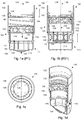
Figure 1a is a cross-sectional side view of a suction valve in a closed state, -
figure 1b is a cross-sectional side view of the suction valve offigure 1a in an open state, -
figure 1c is a cross-sectional top view of the suction valve offigures 1a and 1b , -
figure 1d is a cross-sectional perspective view of the suction valve offigures 1a-c , -
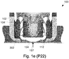
figure 1e is a partial, cross-sectional side view of the suction valve offigures 1a and 1b in an intermediate state, -
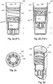
figure 2a is a cross-sectional side view of a suction valve according to a second embodiment and in a closed state, -
figure 2b is a cross-sectional side view of the suction valve offigure 2a in an open state, -
figure 2c is a cross-sectional top view of the suction valve offigures 2a and 2b , and -
figure 2d is a cross-sectional perspective view of the suction valve offigures 2a-c , -
figure 3 schematically illustrates a system comprising a suction valve, and -
figure 4 is a flowchart of a method of using a system comprising a suction valve. - Referring first to
figures 1a -e, and with reference also tofigure 3 , asuction valve 100 is attached to aconduit 190 that is arranged to provide a suction force for suckingliquid 391 from avessel 302. Theliquid 391 may be liquid food. - The
suction valve 100 comprises anouter body 102 comprising, in one end of thesuction valve 100, asuction inlet 111 and configured to be connected to the conduit 190 (the conduit also referred to withreference numeral 306 infigure 3 ) at another end of thesuction valve 100. - An
inner body 104 is movably arranged within theouter body 102. - The
outer body 102 and theinner body 104 may be concentrically arranged in relation to each other around alongitudinal axis 108. Theinner body 104 is then arranged to move in directions -Y, Y along thelongitudinal axis 108. As exemplified, thesuction valve 100 is generally circularly symmetric with respect to thelongitudinal axis 108. However, other symmetries may be foreseen in other embodiments, such as any polygon-shaped cross-section. - A
spring 106 arranged to exert aforce 196 on theinner body 104 to press theinner body 104 in a direction -Y towards thesuction inlet 111, such that theinner body 104 seals thesuction inlet 111 to thereby set thesuction valve 100 in a closed state P1. - The
inner body 104 is arranged to move in a direction Y away from thesuction inlet 111 when asuction force 195 applied by theconduit 190 is larger than theforce 196 exerted by thespring 106, to thereby set thesuction valve 100 in an open state P21 to allowliquid 391 to be sucked from thevessel 302, through thesuction inlet 111 and into theconduit 190. - The
suction inlet 111 of theouter body 102 has anend suction inlet 112 and alateral suction inlet 114. Theinner body 104 has anend sealing surface 110, alateral sealing surface 116 and aliquid passage 118 for allowing liquid to flow through theinner body 104. In the closed state P1, theinner body 104 is in a first position along thelongitudinal axis 108, in which first position theend sealing surface 110 seals theend suction inlet 112 while thelateral sealing surface 116 seals thelateral suction inlet 114. As exemplified, thelateral inlet 114 is in the form of a plurality of circular holes distributed around the circumference of theouter body 102. However, thelateral inlet 114 may be comprised of any appropriate number of holes having any appropriate shape and distribution on theouter body 102. - In the open state P21, the
inner body 104 is in a second position along thelongitudinal axis 108, in which second position theend sealing surface 110 is retracted from theend suction inlet 112 and thelateral sealing surface 116 is retracted from thelateral suction inlet 114. - The
inner body 104 is arranged to move in the direction Y away from theend suction inlet 111 when anexternal force 197 that is applied on theinner body 104 is larger than the force exerted by thespring 106. Theexternal force 197 can be applied by pressing of thesuction valve 100 towards a bottom of thevessel 302. Thereby thesuction valve 100 can be set in an intermediate state P22 to allowliquid 391 to be sucked from thevessel 302 through theend suction inlet 112 and into theconduit 190. - In the intermediate state P22, the
inner body 104 is in a third position along thelongitudinal axis 108. In the third position, theend sealing surface 110 is retracted from theend suction inlet 112 while thelateral sealing surface 116 still seals thelateral suction inlet 114. - The
inner body 104 has alateral inlet 120 that is located above theliquid passage 118 of theinner body 104. When thesuction valve 100 is set in the open state P21, acircumferential channel 122 leading to thelateral inlet 120 of theinner body 104 is formed between theouter body 102 and theinner body 104. Thecircumferential channel 122 thereby allows liquid 191 to flow through thelateral inlet 120 of theinner body 104 and into theconduit 190. Thiscircumferential channel 122 may then improve cleaning of thesuction valve 100, when cleaning liquid is sucked through thesuction valve 100. Thelateral inlet 120 is in the form of a plurality of circular holes distributed around the circumference of theinner body 104. However, thelateral inlet 120 may be comprised of any appropriate number of holes having any appropriate shape and distribution on theinner body 104. - The
inner body 104 has aprotrusion 124 that protrudes, when thesuction valve 100 is in the closed state P1, beyond theend suction inlet 112 of theouter body 102. As illustrated infigures 1a-e , theprotrusion 124 may have a convex shape. However, other embodiments may comprise protrusions having other shapes, for example protrusions having the shape of truncated cones. - Such a
protrusion 124 may be arranged on theend sealing surface 110, theend sealing surface 110 being supported bylegs 126 that protrudes from a cylindricallyshaped section 128 of theinner body liquid passage 118 of theinner body spacings 129 between thelegs 126. Whereas thesuction valve 100 is exemplified having eightequidistant legs 129, it is to be noted that the some embodiments may comprise any other number of legs having any appropriate length and distribution along the circumference of the cylindricallyshaped section 128. - When the
suction valve 100 is in the intermediate state P22 (seeFig. 1e ), thelateral inlet 114 of theouter body 102 is sealed while theend inlet 112 of theouter body 102 is open. This intermediate state P21 is advantageous in that it enables an effective suction of liquid from thevessel 302 at a point in time when thevessel 302 is almost empty, as indicated by alow liquid level 393 infigure 3 . When the liquid in thevessel 302 is at thelow liquid level 393, then thelateral inlet 114 may be located above thelow liquid level 393. However, by the fact that thelateral inlet 114 is sealed by thelateral sealing surface 116, drawbacks related to sucking the atmosphere above thelow liquid level 393 are avoided. As the skilled person will realize, it is in most food product contexts disadvantageous to suck a mixture of liquid and, e.g., air via theconduit 190. At the same time, thesuction valve 100 has a high suction capacity when it is in the open state P21, since liquid then can be sucked through both theend suction inlet 112 and thelateral suction inlet 114. - The
outer body 102 may comprises afirst part 130 and asecond part 132 that are attached to each other to hold theinner body 104. Thesecond part 132 may comprise a firstspring abutment surface 134 that faces theinner body 104 and theinner body 104 may comprise a secondspring abutment surface 136 that faces thesecond part 132. Thespring 106 is then in contact with and biased between the first and the second spring abutment surfaces 134, 136. Further, thefirst part 130 may comprise afirst stop surface 138 against which theinner body 104 abut when thesuction valve 100 is in the closed state P1 and thesecond part 132 may comprise asecond stop surface 140 against which theinner body 104 abut when thesuction valve 100 is in the open state P21. As can be seen infigures 1a-b , thefirst stop surface 138 ensures a tight fit between theouter body 102 and theinner body 104 and thereby a secure sealing of thelateral inlet 114 of theouter body 102. Moreover, thesecond stop surface 140 provides a limit on how far the inner body 1034 may move in the Y-direction. -
Figures 2a -d illustrate asuction valve 200 that is similar to thesuction valve 100 illustrated infigures 1a-d . Thesuction valve 200 offigures 2a-d illustrates more compact embodiments that the embodiments illustrated infigures 1a-e . Infigures 2a and 2d , thesuction valve 200 is in the closed state P1 and infigure 2b it is in the open state P21. Thesuction valve 200 comprises anouter body 202 and aninner body 204 and aspring 206. Similar to thesuction valve 100, theouter body 202 comprises afirst part 230 and asecond part 232 that are attached to each other to hold theinner body 204. Thesecond part 232 is configured, similar to thesecond part 132 of thesuction valve 100, to be connected to a (not shown infigures 2a-d ) conduit that is arranged to provide a suction force for sucking liquid from a vessel. - In addition to features that correspond to features of the
suction valve 100, thesecond part 232 of thesuction valve 200 has a cylindrically shapedsection 242 having cut-outs 244. The cylindrically shapedsection 242 is configured such that it operates as a spring abutment surface that is similar to thespring abutment surface 134 of thesecond part 132 of thesuction valve 100 infigures 1a-e . The cut-outs 244 maximize the internal cross-section of theouter body 232 while retaining the spring abutment capability of the cylindrically shapedsection 242. Consequently, the cut-outs 244 maximize the flow of liquid when thesuction valve 200 is in the open state P21 when liquid is being sucked through thesuction valve 200. - Turning now to
figure 3 , asuction system 300 for sucking liquid 391 from avessel 302 is schematically illustrated. Thesuction system 300 comprises a suction valve such as thesuction valve 100 offigures 1a-e (or thesuction valve 200 offigures 2a-d ). Thesuction system 300 further comprises aconduit 306 to which thesuction valve 100 is attached. Asuction device 308, e.g. an appropriately configured suction pump, is connected to theconduit 306 to provide a suction force for sucking liquid 391 from thevessel 302. Thesuction device 308 connects to further arrangements via afurther conduit 312, the details of which are outside the scope of the present disclosure. - Turning now to
figure 4 , and with continued reference tofigures 1a-e andfigure 3 , a method of using thesystem 300 for sucking liquid 391 from avessel 302 comprises a number of actions that begin with a lowering 410 of thesuction valve 100 into the liquid 391. Suction is then applied 420 by thesuction device 308 to place the suction valve in the open state P21 and thereby remove liquid 391 from thevessel 302 by drawing the liquid into theend suction inlet 112 and thelateral suction inlet 114 of theouter body - A further action of applying
suction 430 by thesuction device 308 may then be performed. In this application ofsuction 430, a suction force is applied that is smaller than the force exerted by thespring 106. Thesuction valve 100 is thereby placed in the closed state P1. By pressing 440 theprotrusion 124 of theinner body 104 towards abottom part 310 of thevessel 302, thesuction valve 100 is then placed in the intermediate state P22 to thereby remove liquid 391 from thevessel 302 by drawing the liquid into theend suction inlet 112 while thelateral suction inlet 114 is closed. That is, liquid 393 at the bottom 310 of thevessel 302 is being sucked, providing the advantages as described above. - From the description above follows that, although various embodiments of the invention have been described and shown, the invention is not restricted thereto, but may also be embodied in other ways within the scope of the subject-matter defined in the following claims.
Claims (13)
- A suction valve (100, 200) configured to be attached to a conduit (190) that is arranged to provide a suction force for sucking liquid (391) from a vessel (302), the suction valve (100, 200) comprising- an outer body (102, 202) comprising a suction inlet (111) and configured to be connected to the conduit (190), and- an inner body (104, 204) movably arranged within the outer body (102, 202),wherein- a spring (106, 206) arranged to exert a force on the inner body (104, 204) to press the inner body (104, 204) in a direction (-Y) towards the suction inlet (111), such that the inner body (104, 204) seals the suction inlet (111) to thereby set the suction valve (100, 200) in a closed state (P1), and- the inner body (104, 204) is arranged to move in a direction (Y) away from the suction inlet (111) when a suction force (195) applied by the conduit (190) is larger than the force exerted by the spring (106), to thereby set the suction valve (100, 200) in an open state (P21) to allow liquid (391) to be sucked from the vessel (302), through the suction inlet (111) and into the conduit (190).
- The suction valve (100, 200) of claim 1, wherein- the outer body (102, 202) and the inner body (104, 204) are concentrically arranged in relation to each other around a longitudinal axis (108) and,- the inner body is arranged to move in the directions (-Y, Y) along the longitudinal axis (108).
- The suction valve (100, 200) of claim 2, wherein- the suction inlet (111) of the outer body (102, 202) comprises an end suction inlet (112) and a lateral suction inlet (114),- the inner body (104, 204) comprises an end sealing surface (110), a lateral sealing surface (116) and a liquid passage (118) for allowing liquid to flow through the inner body (104, 204), and- in the closed state (P1), the inner body (104, 204) is in a first position along the longitudinal axis (108), in which first position the end sealing surface (110) seals the end suction inlet (112) while the lateral sealing surface (116) seals the lateral suction inlet (114).
- The suction valve (100, 200) of claim 3, wherein- in the open state (P21), the inner body (104, 204) is in a second position along the longitudinal axis (108), in which second position the end sealing surface (110) is retracted from the end suction inlet (112) and the lateral sealing surface (116) is retracted from the lateral suction inlet (114).
- The suction valve (100, 200) of claim 3 or claim 4, wherein- the inner body (104, 204) is arranged to move in a direction (Y) away from the end suction inlet (111) when an external force (197) that is applied on the inner body (104, 204), by pressing of the suction valve (100, 200) towards the vessel (302), is larger than the force exerted by the spring (106, 206), to thereby set the suction valve (100, 200) in an intermediate state (P22) to allow liquid (391) to be sucked from the vessel (302), through the end suction inlet (112) and into the conduit (190).
- The suction valve (100, 200) of claim 5, wherein- in the intermediate state (P22), the inner body (104, 204) is in a third position along the longitudinal axis (108), in which third position the end sealing surface (110) is retracted from the end suction inlet (112) and the lateral sealing surface (116) seals the lateral suction inlet (114).
- The suction valve (100, 200) of any of claims 1 to 6, wherein- the inner body (104, 204) comprises a lateral inlet (120, 220), and- when the suction valve (100, 200) is set in the open state (P21), a circumferential channel (122) leading to the lateral inlet (120) of the inner body (104, 204) is formed between the outer body (102, 202) and the inner body (104, 204), the circumferential channel (122) thereby allowing liquid (191) to flow through the lateral inlet (120) of the inner body (104, 204) and into the conduit (190).
- The suction valve (100, 200) of any of claims 3 to 7, wherein the inner body (104, 204) comprises a protrusion (124) that protrudes, when the suction valve (100, 200) is in the closed state (P1), beyond the end suction inlet (112) of the outer body (102, 202).
- The suction valve of claim 8, wherein the protrusion (124) is arranged on the end sealing surface (110), the end sealing surface (110, 210) being supported by legs (126) that protrudes from a cylindrically shaped section (128) of the inner body (104, 204), such that the liquid passage (118) of the inner body (104, 204) is formed by spacings (129) between the legs (126).
- The suction valve (100, 200) of any of claims 1 to 9, wherein- the outer body (102, 202) comprises a first part (130, 230) and a second part (132, 232) that are attached to each other to hold the inner body (104, 204),- the second part (132, 232) comprises a first spring abutment surface (134) that faces the inner body (104, 204),- the inner body (104, 204) comprises a second spring abutment surface (136) that faces the second part (132, 232),- the spring (106, 206) is in contact with and biased between the first and the second spring abutment surfaces (134, 136),- the first part (130, 230) comprises a first stop surface (138) against which the inner body (104, 204) abut when the suction valve (100, 200) is in the closed state (P1),- the second part (132, 232) comprises a second stop surface (140) against which the inner body (104, 204) abut when the suction valve (100, 200) is in the open state (P21).
- A suction system (300) for sucking liquid (391) from a vessel (302), the suction system comprising- a suction valve (100, 200) according to any of claims 1 to 9,- a conduit (306) to which the suction valve (100, 200) is attached, and- a suction device (308) connected to the conduit (190, 290) to provide a suction force for sucking liquid (391) from the vessel (302).
- A method of using a system (300) according to claim 11 for sucking liquid (391) from a vessel (302), comprising:- lowering (410) the suction valve (100, 200) into the liquid (391), and- applying (420) suction by the suction device (308) to place the suction valve in the open state (P21) and thereby remove liquid (391) from the vessel (302) by drawing the liquid into an end suction inlet (112) and a lateral suction inlet (114) of the outer body (102, 202).
- The method of claim 12, comprising- applying (430) suction by the suction device (308), said suction providing a suction force that is smaller than the force exerted by the spring (106), thereby placing the suction valve (100, 200) in the closed state (P1),- pressing (440) a protrusion (124) of the inner body (104, 204) towards a bottom part (310) of the vessel (302) to place the suction device in the intermediate state (P22) and thereby remove liquid (391) from the vessel (302) by drawing the liquid into the end suction inlet (112) while the lateral suction inlet (114) is closed.
Applications Claiming Priority (1)
| Application Number | Priority Date | Filing Date | Title |
|---|---|---|---|
| EP17209757 | 2017-12-21 |
Publications (2)
| Publication Number | Publication Date |
|---|---|
| EP3502530A1 true EP3502530A1 (en) | 2019-06-26 |
| EP3502530B1 EP3502530B1 (en) | 2020-09-23 |
Family
ID=60811852
Family Applications (1)
| Application Number | Title | Priority Date | Filing Date |
|---|---|---|---|
| EP18212698.7A Active EP3502530B1 (en) | 2017-12-21 | 2018-12-14 | Suction valve |
Country Status (2)
| Country | Link |
|---|---|
| EP (1) | EP3502530B1 (en) |
| WO (1) | WO2019121412A1 (en) |
Families Citing this family (1)
| Publication number | Priority date | Publication date | Assignee | Title |
|---|---|---|---|---|
| CN111623127A (en) * | 2020-05-26 | 2020-09-04 | 佛山市银美精工科技有限公司 | Inhale and float dual-purpose ball and inhale platform that floats of inhaling |
Citations (11)
| Publication number | Priority date | Publication date | Assignee | Title |
|---|---|---|---|---|
| US620936A (en) * | 1899-03-14 | kunzer | ||
| US982680A (en) * | 1910-05-05 | 1911-01-24 | Mesta Machine Co | Air-valve. |
| US1751371A (en) * | 1929-02-11 | 1930-03-18 | John H Viele | Water-locking suction valve for hydrocarbon-fuel-storage tanks |
| DE849206C (en) * | 1951-04-28 | 1952-09-11 | Carl Dr-Ing Krug | Overpressure slide, especially for oil gears of machine tools |
| US4766930A (en) * | 1987-06-03 | 1988-08-30 | Itap S.P.A. | Check valve with self-guided shutter in the valve body |
| FR2659412A1 (en) * | 1990-03-07 | 1991-09-13 | Applic Mach Motrices | Non-return valve device for hydraulic circuits |
| JPH045935A (en) * | 1990-04-23 | 1992-01-09 | Mitsubishi Electric Home Appliance Co Ltd | Vacuum cleaner |
| EP1711731A1 (en) * | 2004-01-30 | 2006-10-18 | Eaton Corporation | Low pressure drop check valve |
| US20120008882A1 (en) * | 2009-04-01 | 2012-01-12 | Hewlett-Packard Development Company Lp | Fluid handling system |
| WO2017027963A1 (en) * | 2015-08-14 | 2017-02-23 | Dana Canada Corporation | Anti-drain valve assembly with integrated fixation function |
| US20170328316A1 (en) * | 2016-05-10 | 2017-11-16 | Accessible Technologies, Inc. | Multi-chamber blowoff valve |
-
2018
- 2018-12-14 EP EP18212698.7A patent/EP3502530B1/en active Active
- 2018-12-14 WO PCT/EP2018/085032 patent/WO2019121412A1/en not_active Ceased
Patent Citations (11)
| Publication number | Priority date | Publication date | Assignee | Title |
|---|---|---|---|---|
| US620936A (en) * | 1899-03-14 | kunzer | ||
| US982680A (en) * | 1910-05-05 | 1911-01-24 | Mesta Machine Co | Air-valve. |
| US1751371A (en) * | 1929-02-11 | 1930-03-18 | John H Viele | Water-locking suction valve for hydrocarbon-fuel-storage tanks |
| DE849206C (en) * | 1951-04-28 | 1952-09-11 | Carl Dr-Ing Krug | Overpressure slide, especially for oil gears of machine tools |
| US4766930A (en) * | 1987-06-03 | 1988-08-30 | Itap S.P.A. | Check valve with self-guided shutter in the valve body |
| FR2659412A1 (en) * | 1990-03-07 | 1991-09-13 | Applic Mach Motrices | Non-return valve device for hydraulic circuits |
| JPH045935A (en) * | 1990-04-23 | 1992-01-09 | Mitsubishi Electric Home Appliance Co Ltd | Vacuum cleaner |
| EP1711731A1 (en) * | 2004-01-30 | 2006-10-18 | Eaton Corporation | Low pressure drop check valve |
| US20120008882A1 (en) * | 2009-04-01 | 2012-01-12 | Hewlett-Packard Development Company Lp | Fluid handling system |
| WO2017027963A1 (en) * | 2015-08-14 | 2017-02-23 | Dana Canada Corporation | Anti-drain valve assembly with integrated fixation function |
| US20170328316A1 (en) * | 2016-05-10 | 2017-11-16 | Accessible Technologies, Inc. | Multi-chamber blowoff valve |
Also Published As
| Publication number | Publication date |
|---|---|
| EP3502530B1 (en) | 2020-09-23 |
| WO2019121412A1 (en) | 2019-06-27 |
Similar Documents
| Publication | Publication Date | Title |
|---|---|---|
| EP3718713B1 (en) | Gripper, grasping device, and industrial robot | |
| US10054238B2 (en) | Bidirectional knife gate valve with a perimeter seat | |
| US20050173668A1 (en) | Self-sealing valve | |
| US9611131B2 (en) | Mini-keg growler cap, components, accessories and designs for the same | |
| US10875196B2 (en) | Gripping device and industrial robot | |
| CA2649724A1 (en) | Pressurized package | |
| TWI745621B (en) | Holding device and industrial robot | |
| WO2018165203A1 (en) | Jar sealing and unsealing device | |
| WO2019121412A1 (en) | Suction valve | |
| US20180362907A1 (en) | Container system for brewing beer | |
| EP1702862A3 (en) | Self-sealing nozzle for a dispensing apparatus | |
| EP2792922B1 (en) | A device and a method for demounting a flange connection | |
| WO2015003194A2 (en) | Fluid drainage container | |
| FI60682B (en) | ANORDNING FOER BEHANDLING AV DELAR AV EN FOERPACKNING | |
| EP3838513B1 (en) | Compressible sectioning suction cup lip and suction cup comprising the lip | |
| JP2010526971A (en) | Dual valve with flexibility | |
| EP3621897B1 (en) | Assembly of an inliner and a tank container | |
| WO2016158301A1 (en) | Substrate suctioning device and substrate suctioning method | |
| US20220055816A1 (en) | Bag side connector for a bib package | |
| EP2614761A3 (en) | Seal system for a vacuum cleaner suction hose | |
| EP3763679A3 (en) | Fluid purification device | |
| GB2583505A (en) | Multi-functional carrier puck | |
| BE743580A (en) | ||
| US9482215B2 (en) | Liquid extraction system with reduced exposure to air | |
| DE1254416B (en) | Outlet valve for transport container |
Legal Events
| Date | Code | Title | Description |
|---|---|---|---|
| PUAI | Public reference made under article 153(3) epc to a published international application that has entered the european phase |
Free format text: ORIGINAL CODE: 0009012 |
|
| STAA | Information on the status of an ep patent application or granted ep patent |
Free format text: STATUS: THE APPLICATION HAS BEEN PUBLISHED |
|
| AK | Designated contracting states |
Kind code of ref document: A1 Designated state(s): AL AT BE BG CH CY CZ DE DK EE ES FI FR GB GR HR HU IE IS IT LI LT LU LV MC MK MT NL NO PL PT RO RS SE SI SK SM TR |
|
| AX | Request for extension of the european patent |
Extension state: BA ME |
|
| STAA | Information on the status of an ep patent application or granted ep patent |
Free format text: STATUS: REQUEST FOR EXAMINATION WAS MADE |
|
| 17P | Request for examination filed |
Effective date: 20200102 |
|
| RBV | Designated contracting states (corrected) |
Designated state(s): AL AT BE BG CH CY CZ DE DK EE ES FI FR GB GR HR HU IE IS IT LI LT LU LV MC MK MT NL NO PL PT RO RS SE SI SK SM TR |
|
| REG | Reference to a national code |
Ref country code: DE Ref legal event code: R079 Ref document number: 602018008099 Country of ref document: DE Free format text: PREVIOUS MAIN CLASS: F16K0015020000 Ipc: B67D0007020000 |
|
| RIC1 | Information provided on ipc code assigned before grant |
Ipc: B67D 7/02 20100101AFI20200327BHEP Ipc: F16K 27/02 20060101ALI20200327BHEP Ipc: F16K 15/02 20060101ALI20200327BHEP Ipc: F16K 1/44 20060101ALI20200327BHEP |
|
| GRAP | Despatch of communication of intention to grant a patent |
Free format text: ORIGINAL CODE: EPIDOSNIGR1 |
|
| STAA | Information on the status of an ep patent application or granted ep patent |
Free format text: STATUS: GRANT OF PATENT IS INTENDED |
|
| INTG | Intention to grant announced |
Effective date: 20200515 |
|
| GRAS | Grant fee paid |
Free format text: ORIGINAL CODE: EPIDOSNIGR3 |
|
| GRAA | (expected) grant |
Free format text: ORIGINAL CODE: 0009210 |
|
| STAA | Information on the status of an ep patent application or granted ep patent |
Free format text: STATUS: THE PATENT HAS BEEN GRANTED |
|
| AK | Designated contracting states |
Kind code of ref document: B1 Designated state(s): AL AT BE BG CH CY CZ DE DK EE ES FI FR GB GR HR HU IE IS IT LI LT LU LV MC MK MT NL NO PL PT RO RS SE SI SK SM TR |
|
| REG | Reference to a national code |
Ref country code: GB Ref legal event code: FG4D |
|
| REG | Reference to a national code |
Ref country code: CH Ref legal event code: EP |
|
| REG | Reference to a national code |
Ref country code: DE Ref legal event code: R096 Ref document number: 602018008099 Country of ref document: DE |
|
| REG | Reference to a national code |
Ref country code: IE Ref legal event code: FG4D |
|
| REG | Reference to a national code |
Ref country code: AT Ref legal event code: REF Ref document number: 1316220 Country of ref document: AT Kind code of ref document: T Effective date: 20201015 |
|
| PG25 | Lapsed in a contracting state [announced via postgrant information from national office to epo] |
Ref country code: NO Free format text: LAPSE BECAUSE OF FAILURE TO SUBMIT A TRANSLATION OF THE DESCRIPTION OR TO PAY THE FEE WITHIN THE PRESCRIBED TIME-LIMIT Effective date: 20201223 Ref country code: GR Free format text: LAPSE BECAUSE OF FAILURE TO SUBMIT A TRANSLATION OF THE DESCRIPTION OR TO PAY THE FEE WITHIN THE PRESCRIBED TIME-LIMIT Effective date: 20201224 Ref country code: FI Free format text: LAPSE BECAUSE OF FAILURE TO SUBMIT A TRANSLATION OF THE DESCRIPTION OR TO PAY THE FEE WITHIN THE PRESCRIBED TIME-LIMIT Effective date: 20200923 Ref country code: SE Free format text: LAPSE BECAUSE OF FAILURE TO SUBMIT A TRANSLATION OF THE DESCRIPTION OR TO PAY THE FEE WITHIN THE PRESCRIBED TIME-LIMIT Effective date: 20200923 Ref country code: BG Free format text: LAPSE BECAUSE OF FAILURE TO SUBMIT A TRANSLATION OF THE DESCRIPTION OR TO PAY THE FEE WITHIN THE PRESCRIBED TIME-LIMIT Effective date: 20201223 Ref country code: HR Free format text: LAPSE BECAUSE OF FAILURE TO SUBMIT A TRANSLATION OF THE DESCRIPTION OR TO PAY THE FEE WITHIN THE PRESCRIBED TIME-LIMIT Effective date: 20200923 |
|
| REG | Reference to a national code |
Ref country code: AT Ref legal event code: MK05 Ref document number: 1316220 Country of ref document: AT Kind code of ref document: T Effective date: 20200923 |
|
| PG25 | Lapsed in a contracting state [announced via postgrant information from national office to epo] |
Ref country code: RS Free format text: LAPSE BECAUSE OF FAILURE TO SUBMIT A TRANSLATION OF THE DESCRIPTION OR TO PAY THE FEE WITHIN THE PRESCRIBED TIME-LIMIT Effective date: 20200923 Ref country code: LV Free format text: LAPSE BECAUSE OF FAILURE TO SUBMIT A TRANSLATION OF THE DESCRIPTION OR TO PAY THE FEE WITHIN THE PRESCRIBED TIME-LIMIT Effective date: 20200923 |
|
| REG | Reference to a national code |
Ref country code: NL Ref legal event code: MP Effective date: 20200923 |
|
| REG | Reference to a national code |
Ref country code: LT Ref legal event code: MG4D |
|
| PG25 | Lapsed in a contracting state [announced via postgrant information from national office to epo] |
Ref country code: EE Free format text: LAPSE BECAUSE OF FAILURE TO SUBMIT A TRANSLATION OF THE DESCRIPTION OR TO PAY THE FEE WITHIN THE PRESCRIBED TIME-LIMIT Effective date: 20200923 Ref country code: RO Free format text: LAPSE BECAUSE OF FAILURE TO SUBMIT A TRANSLATION OF THE DESCRIPTION OR TO PAY THE FEE WITHIN THE PRESCRIBED TIME-LIMIT Effective date: 20200923 Ref country code: PT Free format text: LAPSE BECAUSE OF FAILURE TO SUBMIT A TRANSLATION OF THE DESCRIPTION OR TO PAY THE FEE WITHIN THE PRESCRIBED TIME-LIMIT Effective date: 20210125 Ref country code: CZ Free format text: LAPSE BECAUSE OF FAILURE TO SUBMIT A TRANSLATION OF THE DESCRIPTION OR TO PAY THE FEE WITHIN THE PRESCRIBED TIME-LIMIT Effective date: 20200923 Ref country code: LT Free format text: LAPSE BECAUSE OF FAILURE TO SUBMIT A TRANSLATION OF THE DESCRIPTION OR TO PAY THE FEE WITHIN THE PRESCRIBED TIME-LIMIT Effective date: 20200923 Ref country code: SM Free format text: LAPSE BECAUSE OF FAILURE TO SUBMIT A TRANSLATION OF THE DESCRIPTION OR TO PAY THE FEE WITHIN THE PRESCRIBED TIME-LIMIT Effective date: 20200923 |
|
| PG25 | Lapsed in a contracting state [announced via postgrant information from national office to epo] |
Ref country code: PL Free format text: LAPSE BECAUSE OF FAILURE TO SUBMIT A TRANSLATION OF THE DESCRIPTION OR TO PAY THE FEE WITHIN THE PRESCRIBED TIME-LIMIT Effective date: 20200923 Ref country code: IS Free format text: LAPSE BECAUSE OF FAILURE TO SUBMIT A TRANSLATION OF THE DESCRIPTION OR TO PAY THE FEE WITHIN THE PRESCRIBED TIME-LIMIT Effective date: 20210123 Ref country code: AL Free format text: LAPSE BECAUSE OF FAILURE TO SUBMIT A TRANSLATION OF THE DESCRIPTION OR TO PAY THE FEE WITHIN THE PRESCRIBED TIME-LIMIT Effective date: 20200923 Ref country code: AT Free format text: LAPSE BECAUSE OF FAILURE TO SUBMIT A TRANSLATION OF THE DESCRIPTION OR TO PAY THE FEE WITHIN THE PRESCRIBED TIME-LIMIT Effective date: 20200923 Ref country code: ES Free format text: LAPSE BECAUSE OF FAILURE TO SUBMIT A TRANSLATION OF THE DESCRIPTION OR TO PAY THE FEE WITHIN THE PRESCRIBED TIME-LIMIT Effective date: 20200923 |
|
| REG | Reference to a national code |
Ref country code: DE Ref legal event code: R097 Ref document number: 602018008099 Country of ref document: DE |
|
| PG25 | Lapsed in a contracting state [announced via postgrant information from national office to epo] |
Ref country code: SK Free format text: LAPSE BECAUSE OF FAILURE TO SUBMIT A TRANSLATION OF THE DESCRIPTION OR TO PAY THE FEE WITHIN THE PRESCRIBED TIME-LIMIT Effective date: 20200923 |
|
| PLBE | No opposition filed within time limit |
Free format text: ORIGINAL CODE: 0009261 |
|
| STAA | Information on the status of an ep patent application or granted ep patent |
Free format text: STATUS: NO OPPOSITION FILED WITHIN TIME LIMIT |
|
| PG25 | Lapsed in a contracting state [announced via postgrant information from national office to epo] |
Ref country code: DK Free format text: LAPSE BECAUSE OF FAILURE TO SUBMIT A TRANSLATION OF THE DESCRIPTION OR TO PAY THE FEE WITHIN THE PRESCRIBED TIME-LIMIT Effective date: 20200923 Ref country code: SI Free format text: LAPSE BECAUSE OF FAILURE TO SUBMIT A TRANSLATION OF THE DESCRIPTION OR TO PAY THE FEE WITHIN THE PRESCRIBED TIME-LIMIT Effective date: 20200923 Ref country code: MC Free format text: LAPSE BECAUSE OF FAILURE TO SUBMIT A TRANSLATION OF THE DESCRIPTION OR TO PAY THE FEE WITHIN THE PRESCRIBED TIME-LIMIT Effective date: 20200923 |
|
| 26N | No opposition filed |
Effective date: 20210624 |
|
| REG | Reference to a national code |
Ref country code: BE Ref legal event code: MM Effective date: 20201231 |
|
| PG25 | Lapsed in a contracting state [announced via postgrant information from national office to epo] |
Ref country code: IE Free format text: LAPSE BECAUSE OF NON-PAYMENT OF DUE FEES Effective date: 20201214 Ref country code: IT Free format text: LAPSE BECAUSE OF FAILURE TO SUBMIT A TRANSLATION OF THE DESCRIPTION OR TO PAY THE FEE WITHIN THE PRESCRIBED TIME-LIMIT Effective date: 20200923 Ref country code: LU Free format text: LAPSE BECAUSE OF NON-PAYMENT OF DUE FEES Effective date: 20201214 |
|
| PG25 | Lapsed in a contracting state [announced via postgrant information from national office to epo] |
Ref country code: TR Free format text: LAPSE BECAUSE OF FAILURE TO SUBMIT A TRANSLATION OF THE DESCRIPTION OR TO PAY THE FEE WITHIN THE PRESCRIBED TIME-LIMIT Effective date: 20200923 Ref country code: MT Free format text: LAPSE BECAUSE OF FAILURE TO SUBMIT A TRANSLATION OF THE DESCRIPTION OR TO PAY THE FEE WITHIN THE PRESCRIBED TIME-LIMIT Effective date: 20200923 Ref country code: CY Free format text: LAPSE BECAUSE OF FAILURE TO SUBMIT A TRANSLATION OF THE DESCRIPTION OR TO PAY THE FEE WITHIN THE PRESCRIBED TIME-LIMIT Effective date: 20200923 |
|
| PG25 | Lapsed in a contracting state [announced via postgrant information from national office to epo] |
Ref country code: MK Free format text: LAPSE BECAUSE OF FAILURE TO SUBMIT A TRANSLATION OF THE DESCRIPTION OR TO PAY THE FEE WITHIN THE PRESCRIBED TIME-LIMIT Effective date: 20200923 |
|
| PG25 | Lapsed in a contracting state [announced via postgrant information from national office to epo] |
Ref country code: BE Free format text: LAPSE BECAUSE OF NON-PAYMENT OF DUE FEES Effective date: 20201231 |
|
| REG | Reference to a national code |
Ref country code: CH Ref legal event code: PL |
|
| PG25 | Lapsed in a contracting state [announced via postgrant information from national office to epo] |
Ref country code: LI Free format text: LAPSE BECAUSE OF NON-PAYMENT OF DUE FEES Effective date: 20211231 Ref country code: CH Free format text: LAPSE BECAUSE OF NON-PAYMENT OF DUE FEES Effective date: 20211231 |
|
| P01 | Opt-out of the competence of the unified patent court (upc) registered |
Effective date: 20230426 |
|
| PG25 | Lapsed in a contracting state [announced via postgrant information from national office to epo] |
Ref country code: NL Free format text: LAPSE BECAUSE OF NON-PAYMENT OF DUE FEES Effective date: 20200923 |
|
| PGFP | Annual fee paid to national office [announced via postgrant information from national office to epo] |
Ref country code: GB Payment date: 20251223 Year of fee payment: 8 |
|
| PGFP | Annual fee paid to national office [announced via postgrant information from national office to epo] |
Ref country code: FR Payment date: 20251223 Year of fee payment: 8 |
|
| PGFP | Annual fee paid to national office [announced via postgrant information from national office to epo] |
Ref country code: DE Payment date: 20251229 Year of fee payment: 8 |