EP3502467A1 - Wind turbine rotor blade with embedded sensors stitched to drapable plies - Google Patents
Wind turbine rotor blade with embedded sensors stitched to drapable plies Download PDFInfo
- Publication number
- EP3502467A1 EP3502467A1 EP17209674.5A EP17209674A EP3502467A1 EP 3502467 A1 EP3502467 A1 EP 3502467A1 EP 17209674 A EP17209674 A EP 17209674A EP 3502467 A1 EP3502467 A1 EP 3502467A1
- Authority
- EP
- European Patent Office
- Prior art keywords
- rotor blade
- structural element
- optical fiber
- plies
- drapable
- Prior art date
- Legal status (The legal status is an assumption and is not a legal conclusion. Google has not performed a legal analysis and makes no representation as to the accuracy of the status listed.)
- Withdrawn
Links
- 239000013307 optical fiber Substances 0.000 claims abstract description 122
- 230000002787 reinforcement Effects 0.000 claims abstract description 26
- 238000012544 monitoring process Methods 0.000 claims abstract description 21
- 239000000835 fiber Substances 0.000 claims abstract description 20
- 238000000034 method Methods 0.000 claims description 35
- 238000004519 manufacturing process Methods 0.000 claims description 18
- 238000009826 distribution Methods 0.000 claims description 13
- 230000003287 optical effect Effects 0.000 claims description 13
- 238000005452 bending Methods 0.000 claims description 11
- 239000002657 fibrous material Substances 0.000 claims description 10
- OKTJSMMVPCPJKN-UHFFFAOYSA-N Carbon Chemical compound [C] OKTJSMMVPCPJKN-UHFFFAOYSA-N 0.000 claims description 3
- 229920000049 Carbon (fiber) Polymers 0.000 claims description 3
- 239000004760 aramid Substances 0.000 claims description 3
- 229910052799 carbon Inorganic materials 0.000 claims description 3
- 238000005266 casting Methods 0.000 claims description 3
- 230000032798 delamination Effects 0.000 claims description 3
- 239000011521 glass Substances 0.000 claims description 3
- 229920002748 Basalt fiber Polymers 0.000 claims description 2
- 229920006231 aramid fiber Polymers 0.000 claims description 2
- 125000004122 cyclic group Chemical group 0.000 claims description 2
- 230000005611 electricity Effects 0.000 claims description 2
- 239000004744 fabric Substances 0.000 abstract description 14
- 230000003014 reinforcing effect Effects 0.000 abstract description 2
- 239000011347 resin Substances 0.000 description 11
- 229920005989 resin Polymers 0.000 description 11
- 239000000463 material Substances 0.000 description 6
- 230000008569 process Effects 0.000 description 6
- 238000001514 detection method Methods 0.000 description 5
- 230000008901 benefit Effects 0.000 description 4
- 239000002131 composite material Substances 0.000 description 4
- 238000005516 engineering process Methods 0.000 description 4
- 229920002430 Fibre-reinforced plastic Polymers 0.000 description 3
- 239000011162 core material Substances 0.000 description 3
- 239000011151 fibre-reinforced plastic Substances 0.000 description 3
- 230000036541 health Effects 0.000 description 3
- 238000007689 inspection Methods 0.000 description 3
- 238000005259 measurement Methods 0.000 description 3
- 238000012986 modification Methods 0.000 description 3
- 230000004048 modification Effects 0.000 description 3
- 239000012783 reinforcing fiber Substances 0.000 description 3
- 230000004044 response Effects 0.000 description 3
- 239000000470 constituent Substances 0.000 description 2
- 238000010276 construction Methods 0.000 description 2
- 238000013461 design Methods 0.000 description 2
- 230000009977 dual effect Effects 0.000 description 2
- 238000001746 injection moulding Methods 0.000 description 2
- 239000002184 metal Substances 0.000 description 2
- 230000008439 repair process Effects 0.000 description 2
- 230000035882 stress Effects 0.000 description 2
- 238000001721 transfer moulding Methods 0.000 description 2
- 238000009941 weaving Methods 0.000 description 2
- XOJVVFBFDXDTEG-UHFFFAOYSA-N Norphytane Natural products CC(C)CCCC(C)CCCC(C)CCCC(C)C XOJVVFBFDXDTEG-UHFFFAOYSA-N 0.000 description 1
- 239000004677 Nylon Substances 0.000 description 1
- 240000007182 Ochroma pyramidale Species 0.000 description 1
- 240000006365 Vitis vinifera Species 0.000 description 1
- 235000014787 Vitis vinifera Nutrition 0.000 description 1
- 230000001133 acceleration Effects 0.000 description 1
- 230000032683 aging Effects 0.000 description 1
- 229920003235 aromatic polyamide Polymers 0.000 description 1
- 230000009286 beneficial effect Effects 0.000 description 1
- 230000002457 bidirectional effect Effects 0.000 description 1
- 239000004917 carbon fiber Substances 0.000 description 1
- 230000007547 defect Effects 0.000 description 1
- 230000001419 dependent effect Effects 0.000 description 1
- 238000010586 diagram Methods 0.000 description 1
- 230000000694 effects Effects 0.000 description 1
- 239000003733 fiber-reinforced composite Substances 0.000 description 1
- 239000006260 foam Substances 0.000 description 1
- 239000003365 glass fiber Substances 0.000 description 1
- 238000009787 hand lay-up Methods 0.000 description 1
- 238000001802 infusion Methods 0.000 description 1
- 230000000977 initiatory effect Effects 0.000 description 1
- 238000009434 installation Methods 0.000 description 1
- 238000013507 mapping Methods 0.000 description 1
- VNWKTOKETHGBQD-UHFFFAOYSA-N methane Chemical compound C VNWKTOKETHGBQD-UHFFFAOYSA-N 0.000 description 1
- 238000000465 moulding Methods 0.000 description 1
- 229920001778 nylon Polymers 0.000 description 1
- 230000000737 periodic effect Effects 0.000 description 1
- 239000011120 plywood Substances 0.000 description 1
- 229920000728 polyester Polymers 0.000 description 1
- 238000012805 post-processing Methods 0.000 description 1
- 230000003252 repetitive effect Effects 0.000 description 1
- 230000035945 sensitivity Effects 0.000 description 1
- 238000009958 sewing Methods 0.000 description 1
- 238000011179 visual inspection Methods 0.000 description 1
Images





Classifications
-
- F—MECHANICAL ENGINEERING; LIGHTING; HEATING; WEAPONS; BLASTING
- F03—MACHINES OR ENGINES FOR LIQUIDS; WIND, SPRING, OR WEIGHT MOTORS; PRODUCING MECHANICAL POWER OR A REACTIVE PROPULSIVE THRUST, NOT OTHERWISE PROVIDED FOR
- F03D—WIND MOTORS
- F03D17/00—Monitoring or testing of wind motors, e.g. diagnostics
-
- F—MECHANICAL ENGINEERING; LIGHTING; HEATING; WEAPONS; BLASTING
- F03—MACHINES OR ENGINES FOR LIQUIDS; WIND, SPRING, OR WEIGHT MOTORS; PRODUCING MECHANICAL POWER OR A REACTIVE PROPULSIVE THRUST, NOT OTHERWISE PROVIDED FOR
- F03D—WIND MOTORS
- F03D1/00—Wind motors with rotation axis substantially parallel to the air flow entering the rotor
- F03D1/06—Rotors
- F03D1/065—Rotors characterised by their construction elements
- F03D1/0675—Rotors characterised by their construction elements of the blades
-
- F—MECHANICAL ENGINEERING; LIGHTING; HEATING; WEAPONS; BLASTING
- F05—INDEXING SCHEMES RELATING TO ENGINES OR PUMPS IN VARIOUS SUBCLASSES OF CLASSES F01-F04
- F05B—INDEXING SCHEME RELATING TO WIND, SPRING, WEIGHT, INERTIA OR LIKE MOTORS, TO MACHINES OR ENGINES FOR LIQUIDS COVERED BY SUBCLASSES F03B, F03D AND F03G
- F05B2260/00—Function
- F05B2260/80—Diagnostics
-
- Y—GENERAL TAGGING OF NEW TECHNOLOGICAL DEVELOPMENTS; GENERAL TAGGING OF CROSS-SECTIONAL TECHNOLOGIES SPANNING OVER SEVERAL SECTIONS OF THE IPC; TECHNICAL SUBJECTS COVERED BY FORMER USPC CROSS-REFERENCE ART COLLECTIONS [XRACs] AND DIGESTS
- Y02—TECHNOLOGIES OR APPLICATIONS FOR MITIGATION OR ADAPTATION AGAINST CLIMATE CHANGE
- Y02E—REDUCTION OF GREENHOUSE GAS [GHG] EMISSIONS, RELATED TO ENERGY GENERATION, TRANSMISSION OR DISTRIBUTION
- Y02E10/00—Energy generation through renewable energy sources
- Y02E10/70—Wind energy
- Y02E10/72—Wind turbines with rotation axis in wind direction
Definitions
- the present invention relates to a rotor blade of a wind turbine.
- the invention particularly relates to rotor blade of a wind turbine wherein one or several sensors are embedded in a structural member of the rotor blade.
- the invention furthermore relates to a wind turbine for generating electrical energy comprising such a rotor blade.
- Wind turbine blades are typically constructions made of composite materials that, compared to conventional metal constructions, exhibit different failure modes, both in terms of damage initiation and propagation. Damage in a composite structure can be difficult to detect with visual inspections - which is the common practice in industry - and damage can propagate so fast that common inspection schedules do not always guarantee the discovery of the fault prior to catastrophic failure.
- a rotor blade of a wind turbine wherein the rotor blade comprises a leading edge section with a leading edge and a trailing edge section with a trailing edge, wherein the leading edge and the trailing edge divide the outer surface of the rotor blade into a suction side and a pressure side.
- the rotor blade further comprises a blade shell which defines the shape of the rotor blade, wherein the blade shell comprises a suction side portion and a pressure side portion, and a structural element for reinforcing and stiffening the structure of the rotor blade, wherein the structural element is made of a stack of drapable plies of continuous fiber material.
- the structural element such as a spar cap of the rotor blade by infused and cured resin.
- the rotor blade is characterized in that the structural element comprises at least one optical fiber embedded in the stack of drapable plies of continuous fiber material for monitoring structural characteristics and/or integrity of the structural element, wherein the optical fiber comprises at least one sensor, and the optical fiber (21) is stitched onto one of the drapable plies of the stack.
- the invention proposes a novel system that can be used for structural health monitoring (SHM) of wind turbine rotor blades.
- the system employs drapable 'smart' plies or mats with sensors stitched onto the drapable plies or mats.
- the plies are drapable as an intrinsic property of the plies only prior to the resin infusion and curing of the stack of the plies to form the structural element. Once the stack of the drapable plies is resin infused and the resin subsequently cured neither the resulting structural element is drapable nor are the constituent plies of the stack forming the structural element are drapable thereafter.
- These structures - or structural elements - serve the dual purpose of load carrying and strain sensing along the main stress paths of overall blade components, e.g. spar caps or root section reinforcement parts of the rotor blade.
- the sensor(s) is/are optical fiber based
- the sensor(s) is/are immune to lightning strikes.
- the provision of the sensor(s) can be carried out in a protected environment and can even be carried out completely separate from the typically rough industrial environment where the rotor blade is manufactured.
- the plies or mats of continuous fiber material that are generally used to be laid up in the blade mould by hand lay-up or robotic arm lay-up during blade manufacturing by stacking the plies are provided with the optical fibers having the sensors before the laying-up of these plies in the blade mould.
- the optical fibers are stitched onto one or more of the plies, thereby forming the smart ply or smart plies and then these smart ply or smart plies are laid up in the blade mould and further manufacturing of the blade is performed.
- the smart ply is the mat or fabric made of continuous fiber material onto which the optical fiber or fibers having the sensor is stitched.
- the present invention is in principle applicable to any structural element of the rotor blade.
- Advantageous applications focus on components which bear a load carrying role and which are prone to stress and strain.
- Concrete examples thereof are spar caps at the pressure and suction side of the blade shell or so-called root section reinforcement parts, and also the web between the spar caps.
- Spar caps are typically connected in an I-beam shape to the web (or “beam” or “spar"), wherein the spar caps basically carry longitudinal loads while the web mostly carries shear load from bending moments.
- the root section reinforcement parts are typically inserted into the root section of the laminate of the blade shell and reinforce the heavily loaded root section of the rotor blade.
- the root section reinforcement parts typically become thinner in a direction away from the root and, thus, "fade out” or merge with the standard fiber-reinforced composite material of the blade shell.
- Embedding one or more sensors in these root section reinforcement parts is advantageous as these parts are manufactured before laying them out in the mold and can thus be prepared specifically for the purpose of providing means to monitor e.g. the casted laminate quality in a reliable, repetitive and elegant manner.
- the fibers of the continuous fiber material plies may in principle comprise any type of fiber.
- Proven materials used as fibers in the continuous fiber material for wind turbine rotor blades include glass, carbon, aramid and/or basalt fibers.
- the structural element comprising such smart ply is referred to as 'smart' structural element.
- One purpose of the sensor(s) embedded into the structural elements is to monitor the characteristics of the fiber-reinforced plies of the structural element and, thus of the structural element itself and as a consequence, those of the rotor blade that comprises at least one such structural element. This comprises in particular the monitoring of delamination, cracks, in particular transverse cracks, and/or a fracture of the structural element.
- the presented system has a "dual" working principle: First, if one of the embedded sensors happens to be in the "process zone" of the damage, this will show as a local strain increase at the sensor. Second, if the damage is far away from the sensor(s) (i.e. in another zone of the rotor blade), but affects the global structural response of the blade - especially in terms of flapwise bending moment distribution - this will show in the system as different strain distribution throughout the "smart" structural elements.
- a reliable detection of these failures at an early stage is highly advantageous for the owner of a wind turbine, as thus costly service and repair works on the rotor blades can be avoided, or at least planned efficiently beforehand. Additionally, catastrophic failures can be avoided.
- monitoring the structural characteristics and/or integrity of the structural element may include monitoring delamination, cracks, in particular transverse cracks, and/or a fracture of the structural element.
- Another purpose of the sensor(s) embedded into the structural elements is to monitor the changes in the strain distribution throughout the structural element which result from the global bending and/or twisting of the rotor blade subject to cyclic aerodynamic and gravitational forces.
- the detection of these configurational changes in the rotor blade may, first, also contribute to better calculate and foresee e.g. aging of certain components. Second, however, it is advantageous to have information on changes in the shape such as bending and/or twisting that can be obtained from measured strains through proper calibration, to control and regulate the operation of the wind turbine. For instance, individual pitch control could be improved based on input data which are based on the monitoring of a structural element with an embedded sensor according to this invention.
- An additional advantage of the embedded sensor(s) as conceived in the present invention is that the data acquired by the proposed system could be used in aero-structural control paradigms, such as e.g. flutter control.
- the optical fiber is aligned substantially in lengthwise direction of the rotor blade.
- the "lengthwise" direction of the rotor blade is referred to as the direction, or orientation, which extends from the root to the tip of the rotor blade.
- the length of the optical fiber exceeds five per cent, in particular ten per cent, even more particularly twenty percent of the length of the rotor blade.
- the optical fiber can also go to the tip, turn around and come back to the root such that not only the reflected but also the transmitted light is measurable at the root. If the optical fiber comes back to the root than its length is equal to or more than double the length of the blade.
- any fiber optic sensor can be used.
- a distributed Bragg reflector in particular a fiber Bragg grating (FBG), constructed in a short segment of the optical fiber has been proven to be a preferred choice, as devised by the inventor.
- Multiple FBGs may be inserted or formed in the same optical fiber.
- a "short" segment is to be understood as a segment of the optical fiber which has a length which is less than ten per cent of the length of the stitched optical fiber itself.
- the segment of the optical fiber may have a length which is even less than five per cent of the length of the stitched optical fiber.
- the fiber Bragg grating is to be understood as an arrangement wherein a periodic variation in the refractive index of the core of fiber leads to a wavelength-specific dielectric mirror.
- the function of the fiber Bragg grating is the detection of a failure or damage in the fiber-reinforced plastic material.
- FBG embedded fiber Bragg grating
- the damage is far away from the FBG, namely in another zone of the rotor blade, but affects the global structural response of the blade, this will show in the system as different strain distribution compared to the pristine one throughout the "smart" structural elements.
- the optical fiber comprises a plurality of sensors which are distributed lengthwise in the optical fiber.
- the advantage of providing a plurality of sensors distributed lengthwise along the optical fiber is that information about the lengthwise position along the optical fiber is provided, if the sensor detects a failure in the fiber-reinforced plies or of the structural element.
- a spanwise distribution of sensors allows a high resolution reconstruction the spanwise strain distribution and/or bending response of the rotor blade.
- another significant advantage is that there is more chance to capture a damage because there are more measurement points and better resolution of the strain distribution. Too few FBG can miss certain damages developing far away from them.
- the rotor blade comprises a plurality of optical fibers with respective sensors, which are in particular arranged substantially in parallel to each other in the drapable plies.
- the optical fiber in the rotor blade of the wind turbine, extends from root to tip of the blade then turn around, for example with a radius greater than 100mm, and extends from the tip to the root. In this case not only the reflected but also the transmitted light can be measured.
- the optical fibers are connected to an optical interrogator, which itself is connectable to a programmable logic controller (PLC) of the wind turbine.
- PLC programmable logic controller
- the optical interrogator has the purpose to convert the wavelengths reflected by each sensor to mechanical strain values that are transferred to the PLC.
- a dedicated multiplexing method integrated in the system, allows to identify the spanwise position of each sensor.
- Dedicated data post-processing within the PLC determines structural faulty states of the rotor blade and/or accurately determines the position of failure in the structural element if a plurality of sensors is distributed with adequate spatial resolution in the optical fiber.
- the optical interrogator is situated in the root section of the rotor blade or in the hub of the wind turbine.
- any drapable ply may be covered to a smart ply.
- the optical fiber is only stitched after the drapable ply has been manufactured, there is no need for modifying the structural design and/or the manufacturing process for the drapable ply to include the optical fibers. Also, since the stitching operation of the optical fiber onto the drapable ply is independent of the manufacturing process of the drapable ply itself, the orientation of the optical fibers with respect to the ply can be easily manipulated and secured. Also, stitching can be undone in parts or completely, and new orientation of the optical fiber with respect to the drapable ply can be easily obtained by realigning and re-stitching the optical fiber onto the drapable ply, as per the requirement of the user. This freedom to control the orientation of the optical fiber may be very helpful.
- the invention is finally also related to a wind turbine for generating electricity comprising at least one rotor blade as described above.
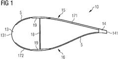
- FIG 1 shows a cross-sectional view of a rotor blade 10 of a wind turbine.
- the rotor blade 10 comprises a leading edge section 13 with a leading edge 131 and, opposite to the leading edge 131, a trailing edge section 14 with a trailing edge 141.
- the leading edge 131 and the trailing edge 141 divide the outer surface of the rotor blade 10 into a suction side 15 and a pressure side 16.
- the geometry, i.e. the shape, of the rotor blade 10 is defined by the blade shell 5 of the rotor blade 10.
- the blade shell 5 can be divided into a suction side portion 171 and a pressure side portion 172.
- a web 18 which extends between the suction side portion 171 and the pressure side portion 172 of the blade shell.
- the web 18 typically extends over most of the length of the rotor blade 10, i.e. from the root section to the tip section of the rotor blade.
- the blade shell 5 is reinforced by a spar cap 19.
- both the suction side portion 171 and the pressure side portion 172 of the blade shell 5 are reinforced by a structural element or "sub-component", namely the spar cap 19 which is an example of the structural element in the present technique.
- Other examples of structural element, as used herein for the present technique are web 18 or the root section (not shown in FIG 1 ) of the rotor blade 10.
- the blade shell 5 is typically configured as a laminate comprising a fiber-reinforced plastic material or fabrics and core materials (e.g. balsa wood, ply-wood, foam).
- core materials e.g. balsa wood, ply-wood, foam.
- the fiber-reinforced plastic material or fabrics are relatively thin, typically and depending on the spanwise position only one to ten millimeter thick, while the core may amount to a thickness up to a few centimeters. As can be seen in the schematic illustration of FIG 1 , the thickness of the blade shell 5 varies.
- the thickness of the blade shell 5 may depend on the chordwise position between the leading edge 131 and the trailing 141. Second, the thickness also depends on whether the blade shell 5 is part of the suction side portion 171 or the pressure side portion 172. Another variation in the thickness is based on the position in lengthwise or spanwise direction, i.e. whether the blade shell 5 is closer to the root section or closer to the tip section of the rotor blade 10. In spanwise positions very close to the root of the rotor blade 10, the blade section profile might look considerably different from the one represented in FIG 1 with blade shell 5 thicknesses considerably increasing from what previously specified (up to few centimeters) and shape transitioning from aerodynamic to cylindrical shapes.
- FIG 3 shows a part of a conventionally known spar cap 191 and FIG 2 schematically depicts manufacturing of the conventionally known spar cap 191 of the wind turbine rotor blade 10.
- FIG 4 shows the conventionally known spar cap 191 as located in the blade 10.
- the conventional spar cap 191 is manufactured by hand or robotic layup of a number of continuous fiber mats or fabrics, also referred to as plies 34.
- one such continuous fiber material ply 34 hereinafter also referred simply to as conventional ply 34, is placed in a blade mould 99 and thereafter additional conventional plies 34 are placed atop each other to form a stack of conventional plies 34.
- the number of conventional plies 34 placed in the stack so formed depends on the thickness of the spar cap 191 to be achieved.
- the conventional plies 34 are drapable i.e. the conventional plies 34 can be folded and bent like a fabric or cloth.
- the plies 34 can have different lengths.
- These conventional plies 34 are preferably unidirectional fabrics i.e. substantially the reinforcing fibers within the plies 34 run in one direction for example some weavers of unidirectional fabrics, term a fabric with only 75% of its weight in one direction as a unidirectional (UD) fabric, whilst for others the unidirectional designation only applies to those fabrics with more than 90% of the fiber weight in one direction.
- other plies 34 may not be UD plies, but instead may be bidirectional or omnidirectional mats.
- the stack of plies 34 is casted, i.e. formed into a desired physical form, to form the spar cap 191 i.e. for example by raisin injection moulding.
- FIG 4 shows the conventional plies 34 to depict the arrangement of plies 34 in the spar cap 191.
- the present technique differs from the conventionally known spar cap 191 and the other aspects described in FIGs 1 to 4 , in the use of 'smart ply' 35 or 'smart plies' 35 schematically shown in FIGs 5 and 6 , and subsequently in FIGs 15 and 16 .
- the smart ply 35 is made from a conventionally known ply 34 or mat 34 or fabric 34 on which an optical fiber 21 is attached by stitching, depicted by stitches 25.
- the stitches 25 are formed as a result of sewing manually or by using a robotic arm and thereby affixing the optical fiber 21 to the components of the ply 34, for example to the reinforcing-fiber bundle 29 such as glass-fiber bundle or carbon fiber bundle of the ply 34, and preferably of the unidirectional ply 34 to form the 'smart' unidirectional (UD) ply 35 as shown in FIG 6 .
- the optical fiber 21 includes one or more sensors 22.
- Such smart plies 35 are used during the manufacturing of the structural element of the present technique, for example during the manufacturing of the spar cap 19 of FIG 1 or the web 18 of FIG 1 .
- FIG 9 schematically depicts a part of the spar cap 19 having the embedded optical fibers 21 resulting from the process of FIG 8 .
- the spar cap 19 is casted by using resin injection moulding, such as Vacuum Assisted Resin Transfer Molding (VARTM) or Vacuum Injected Molding (VIM).
- VARTM Vacuum Assisted Resin Transfer Molding
- VIM Vacuum Injected Molding
- the structural element i.e. in the present example is the spar cap 19, includes a stack of drapable plies 34,35 of continuous fiber material and includes one or more optical fibers 21 embedded in the stack of drapable plies 34,35.
- One or more of the optical fibers 21 are stitched onto one or more of the drapable plies, i.e. the smart plies 35, of the stack and each optical fiber 21 includes at least one sensor 22.
- the sensors 22 are used for monitoring structural characteristics and/or integrity of the structural element, i.e. of the spar cap 19 in the present example.
- the smart plies 35 are formed before the casting of the structural element, i.e. before forming the spar cap 19 in the present example, or in other words before the plies 34,35 are laid-up in the mould 99 of FIG 8 and before the VARTM or VIM is applied.
- the position of the optical fiber 21 within the structural element i.e. the spar cap 19 in the present example, can be predetermined and even a desired pattern of layout or orientations of the sensors 22 can be provided.
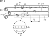
- FIG 7 shows an exemplary smart ply 35 that is integrated into the structural element, i.e. the spar cap 19, the web 18, or a root section reinforcement part of the rotor blade 10 and has a plurality of optical fibers 21 with sensors 22.
- three optical fibers 21, namely a first optical fiber 211, a second optical fiber 212 and a third optical fiber 213 can be seen. All three optical fibers 211, 212, 213 are arranged substantially parallel to each other. They are also arranged in lengthwise direction of the unidirectional smart plies 35.
- Each optical fiber 21 is provided with sensors 22 wherein one sensor 22 is shown separately in more detail in FIG 7 .
- Each of the optical fiber 211,212,213 is attached in the smart ply 35 by stitches 25.
- the stitches 25 fastening the corresponding optical fiber 21 may be spread along the length of the optical fiber 21 so that the optical fiber 21 is arranged in the smart ply 35 in a desired orientation and position.
- the stitching can be performed using threads for example polyester, nylon, glass, carbon, aramid yarns.
- each sensor 22 can exemplarily be designed as fiber Bragg gratings. This means that each sensor 22 comprises a plurality of gratings 221, wherein each grating 221 partially reflects the light in the optical fiber 21.
- each sensor 22 consists of four gratings 221. Note that this is an example only. In practice, more than four gratings are common. Also note that the dimensions in FIG 7 are not to scale but are chosen such that schematically the principle and concept of the invention become clear. For example, in practice, the distance between adjacent gratings 221 is typically very small, e.g. in the range of hundreds of nanometers.
- the sensors 22 are spaced from each other at a predetermined distance 24. These parts of the optical fibers 21 which are outside and which exit the smart ply 35 are referred to as optical fiber tails 210.
- the optical fiber tails 210 are used to connect the optical fibers 21 with an optical interrogator (not shown in FIG 7 ).
- FIG 10 schematically depicts a top view of an exemplary embodiment of the rotor blade 10 having the spar cap 19 of the present technique and FIG 11 schematically shows a cross-sectional view of the rotor blade 10 of FIG 10 of the wind turbine, this time comprising spar caps 19 which are the structural elements 20, according to the invention.
- the rotor blade 10 of the present technique includes the leading edge 131 and the trailing edge 141 which divide the blade shell 5 into the suction side portion 171 and the pressure side portion 172.
- the web 18 which extends between the suction side portion 171 and the pressure side portion 172 of the blade shell 5.
- the blade shell is reinforced with the spar caps 19.
- each spar cap 19 includes conventional plies 34 and smart plies 35 arranged and formed or casted as a stack and having plurality of optical fibers 21 embedded in the stack and affixed to the smart plies 35 by stitching.
- the smart plies 35 or and/or the conventional plies 34 are not visible as they are fused together, for example by impregnating resin for example by VARTM, to form the structural element 20 i.e. the spar cap 19 in the present example.
- the damage state will most likely influence the strain distribution along the spar caps 19.
- the spar cap strain diagram will have local strain increase or global changes. Therefore, mapping and monitoring the strain distribution along at least one of the spar caps 19 will allow detection of structural damage and avoid structural collapse.
- the provision of structural elements 20, i.e. the spar cap 19 with one or more constituent smart ply 35, with embedded sensors 22 is of great importance.
- the structural elements 20 may well extend over the entire length of the rotor blade 10, i.e. from the root section to the tip section of the rotor blade 10.
- the one or more of the smart plies 35 may be embedded in the structural elements 20, i.e. the spar cap 19 in the present example, such that the optical fibers 21 start a few meters away from the root of the rotor blade 10 and stop a few meters before the tip of the rotor blade 10.
- location and extent of coverage of the rotor blade 10 by the optical fibers 21 can be varied according to the design and desire of the manufacturer.
- FIG 12 shows a schematic top view on a rotor blade 10 with the spar cap 19 as the structural element 20, wherein the structural element 20 comprises embedded optical fibers 21 of which a first optical fiber 211, a second optical fiber 212 and a third optical fiber 213 are shown in FIG 12 . All three optical fiber 211, 212, 213 extend over the entire length of the structural element 20. These optical fibers 211, 212, 213 are arranged basically in parallel to each other. The plurality of optical fibers 211, 212, 213 may simultaneously monitor the strain and load in the structural member 20.
- the provision of several optical fibers 211, 212, 213 is destined to create redundancy in the structural element 20 and thus maintain the functionality of strain detection in the structural element 20 in the event of failure or damage to one or more of the optical fibers 21. Therefore, if for example, the first and the third optical fibers 211, 213 are damaged and do not work properly for example during the blade manufacturing process, then the second optical fiber 212 is used for monitoring the strain and the load in the structural member 20. Redundancy is also beneficial when one or more optical fibers are interrupted due to structural repair.
- FIG 12 also shows an optical interrogator 23 which connects the optical fiber tails 210 with the structural element 20, and more particularly with the smart plies 35 in the structural element 20.
- the optical interrogator 23 is able to convert wavelengths reflected from the sensor 22 into strains. Together with a programmable logic controller, it is possible to determine the lengthwise or spanwise position or location where a failure in the structural element 20 occurs.
- Such an optical interrogator 23 is particularly useful if a plurality of sensors 22 is arranged in lengthwise direction in the optical fibers 21. In the example of FIG 12 , the optical interrogator 23 is located in the root section 11 of the rotor blade 10.
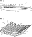
- FIG 13 shows another exemplary embodiment of the structural element 20, namely a root section reinforcement 112, with a plurality of embedded optical fibers 21 according to an exemplary embodiment of the present technique are present.
- the root section reinforcement 112 is made from a stack of drapable plies 34,35 including one or more of the smart plies 35 that have stitched therein the optical fibers 21 having one or more of the sensors 22.
- the root section reinforcement 112 comprises a root end 1121, a tip end 1122, an inner side 1123 and an outer side 1124.
- the root section reinforcement 112 is arranged and prepared to be placed between, i.e. to be "sandwiched", between a fiber layer on its inner end 1123 and between another fiber layer on its outer end 1124.
- the inner end 1123 is destined to face towards the cavity of the rotor blade 10, in case that the root section reinforcement 112 is integrated in a rotor blade 10, and the outer end 1124 of the root section reinforcement 112 is destined to face towards the outside, i.e. towards the surrounding ambience, again in case that the root section reinforcement 112 is integrated in a rotor blade 10.
- the root end 1121 of the root section reinforcement 112 faces towards the root of the rotor blade (or even is part of the root) and the tip end 1122 of the root section reinforcement 112 faces towards the tip end of the rotor blade 10.
- the function of the root section reinforcement 112 is to structurally reinforce and support the root section of the rotor blade 10, as in that section of the rotor blade 10 particularly high bending moments and loads from mechanical joints to the hub typically occur.
- the thickness of the root section reinforcement 112 typically diminishes from its root end 1121 towards its tip end 1122, as it is the case in the exemplary embodiment shown in FIG 10 .
- the root section reinforcement section 112 is made of smart plies 35 and the conventional plies 34.
- the variable thickness of the root section reinforcement 112 is achieved by varying the number of the plies 34, 35 in the stack at different locations of the root section reinforcement 112.
- the root section reinforcement 112 Compared to conventional root section reinforcements, the root section reinforcement 112 according to one embodiment of the present invention comprises a plurality of optical fibers 21. These optical fibers 21 are arranged substantially in lengthwise direction (i.e. from the root end 1121 to the 1122 or vice versa) and substantially in parallel to each other. A substantial number of optical fibers 21 are provided; first, for reasons of redundancy, and second, for providing a detailed monitoring of the structural health of the root section reinforcement 112 and adjacent components of the rotor blade 10.
- FIG 14 schematically depicts a part of the web 18.
- the web 18 is the structural element 20 having the stack of conventional and smart plies 34,35.
- the smart plies 35 are generally sandwiched between the conventional plies 34 as shown in FIG 14 . This keeps the optical fibers 21 and the sensors 22 included therein away from the surface of the structural element 20 and surrounded by the resin which was infused into the stack of the plies 34,35 to form the structural element 20.
- the conventional plies 34 and the resin surrounding the optical fibers 21 protect the optical fibers 21 and the sensors 22 included therein.
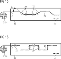
- FIGs 15 and 16 schematically depict different embodiments of the smart ply 35 having different relative orientations of the sensors 22 with respect to the corresponding plies 35, and particularly with respect to the direction of fibers layout or orientation in the UD plies 35.
- the direction of orientation of the reinforcing fibers in the UD plies 35 is schematically depicted in FIGs 15 and 16 by the double headed arrow marked with reference numeral 'd'.
- the optical fiber 21 is stitched on the ply 35 in such a way that some of the sensors 22 are parallel or aligned with the direction d, whereas some other of the sensors 22 are at an angle A with respect to the direction d.
- the angle A may be any angle as desired by the manufactured, and for example 15 degree, 30 degree, 45 degree, 60 degree, 75 degree, etc.
- the optical fiber 21 is stitched on the ply 35 in such a way that some of the sensors 22 are parallel or aligned with the direction d, whereas some other of the sensors 22 are at perpendicular with respect to the direction d, i.e. 90 degree.
- the sensors 22, for both FIGs 15 and 16 that are aligned or parallel to the direction d are used to measure or determine strain along the direction d of the plies 35 whereas the sensors 22 that are perpendicular to the direction d are useful to determine the strain perpendicular to the direction d.
- the sensors 22 that are at different angles A are useful to determine the strain in the smart ply 35 along the corresponding angles. It may be noted that the strain measurement along the smart ply 35 is representative of the strain in the structural element 20.
- FIGs of the present technique with reference to the orientation of the FIG(s) being described.
- the components of the invention can be positioned in a number of different orientations. As such, the directional terminology is used for purposes of illustration and is in no way limiting.
- optical fibers shown in the accompanying figures start at the blade root and terminate at the tip.
- the optical fiber(s) may go from root to tip then turn around with a radius greater than 100mm and come back to the root. In this case not only the reflected but also the transmitted light can be measured.
Landscapes
- Engineering & Computer Science (AREA)
- Life Sciences & Earth Sciences (AREA)
- Sustainable Development (AREA)
- Sustainable Energy (AREA)
- Chemical & Material Sciences (AREA)
- Combustion & Propulsion (AREA)
- Mechanical Engineering (AREA)
- General Engineering & Computer Science (AREA)
- Wind Motors (AREA)
Abstract
A rotor blade for a wind turbine including a leading edge section with a leading edge and a trailing edge section with a trailing edge is presented. The leading and the trailing edges divide the outer surface of the rotor blade into suction and pressure sides. The rotor blade further includes a blade shell which defines the shape of the rotor blade. The blade shell has suction and pressure side portions. The rotor blade includes a structural element, such as a spar cap, a web, a root reinforcement part, etc for load carrying and/or reinforcing the rotor blade. The structural element is made of a stack of drapable continuous fiber mats or fabrics, referred to as plies. The structural element has at least one optical fiber embedded therein for monitoring characteristics of the structural element. The optical fiber includes at least one sensor. The optical fiber is stitched onto one of the drapable plies thereby forming a smart ply. Thus, the stack forming the structural element includes one or more smart plies.
Description
- The present invention relates to a rotor blade of a wind turbine. The invention particularly relates to rotor blade of a wind turbine wherein one or several sensors are embedded in a structural member of the rotor blade. The invention furthermore relates to a wind turbine for generating electrical energy comprising such a rotor blade.
- Wind turbine blades are typically constructions made of composite materials that, compared to conventional metal constructions, exhibit different failure modes, both in terms of damage initiation and propagation. Damage in a composite structure can be difficult to detect with visual inspections - which is the common practice in industry - and damage can propagate so fast that common inspection schedules do not always guarantee the discovery of the fault prior to catastrophic failure.
- The current most common practice for monitoring the structural integrity of a wind turbine blade is through regular inspections that are visually carried out by trained technicians and/or robotic cameras originally developed for pipes inspection. Additional technologies used for remote monitoring of the structural health of composite wind turbine blades are based on the estimation of the fundamental blade frequencies through accelerations measured in the nacelle or in the rotor blade itself. These technologies are usually classified as global since they are based on global characteristics of the blade and are characterized by low sensitivity to damage: only when the structural damage becomes considerably large to affect the global mechanical properties of the structure they become sensitive to the damage.
- Sensor technology in wind turbine blades is limited by the risk and effect of lightning strikes: metal-based sensors are usually discarded due to their electrical conductivity that can be fatal to the sensor system in the event of a lightning strike. Alternative sensing technologies are based on optical sensors such as optical fibers with fiber Braggs gratings (FBG) that allow strain measurements. A main challenge in using FBG in large high production volume composite structures is the instrumentation, especially in large structures: it is a delicate, time-consuming, costly, long process with a high failure rate both during and right after installation. These issues are amplified in rough industrial environments and complex manufacturing processes such as the vacuum assisted resin transfer molding (VARTM) process which uses a mold tool with a vacuum bag and vacuum to assist the resin flow. The VARTM process is, for instance, used by Siemens in its well-known Integral Blade manufacturing process.
- In consideration of the aforesaid, it is an object of the present invention to provide a technique for monitoring the structural characteristics and/or integrity of a rotor blade of a wind turbine throughout its complete lifetime, from manufacturing to decommissioning of the rotor blade.
- This object is achieved by the independent claims. Advantageous modifications and embodiments are disclosed in the dependent claims.
- According to the invention, there is provided a rotor blade of a wind turbine, wherein the rotor blade comprises a leading edge section with a leading edge and a trailing edge section with a trailing edge, wherein the leading edge and the trailing edge divide the outer surface of the rotor blade into a suction side and a pressure side. The rotor blade further comprises a blade shell which defines the shape of the rotor blade, wherein the blade shell comprises a suction side portion and a pressure side portion, and a structural element for reinforcing and stiffening the structure of the rotor blade, wherein the structural element is made of a stack of drapable plies of continuous fiber material. Generally such drapable plies are held together to form the structural element such as a spar cap of the rotor blade by infused and cured resin. The rotor blade is characterized in that the structural element comprises at least one optical fiber embedded in the stack of drapable plies of continuous fiber material for monitoring structural characteristics and/or integrity of the structural element, wherein the optical fiber comprises at least one sensor, and the optical fiber (21) is stitched onto one of the drapable plies of the stack.
- In other words, the invention proposes a novel system that can be used for structural health monitoring (SHM) of wind turbine rotor blades. The system employs drapable 'smart' plies or mats with sensors stitched onto the drapable plies or mats. It may be noted that the plies are drapable as an intrinsic property of the plies only prior to the resin infusion and curing of the stack of the plies to form the structural element. Once the stack of the drapable plies is resin infused and the resin subsequently cured neither the resulting structural element is drapable nor are the constituent plies of the stack forming the structural element are drapable thereafter. These structures - or structural elements - serve the dual purpose of load carrying and strain sensing along the main stress paths of overall blade components, e.g. spar caps or root section reinforcement parts of the rotor blade. As the one or more sensors is/are optical fiber based, the sensor(s) is/are immune to lightning strikes. In addition, the provision of the sensor(s) can be carried out in a protected environment and can even be carried out completely separate from the typically rough industrial environment where the rotor blade is manufactured. In other words, the plies or mats of continuous fiber material that are generally used to be laid up in the blade mould by hand lay-up or robotic arm lay-up during blade manufacturing by stacking the plies are provided with the optical fibers having the sensors before the laying-up of these plies in the blade mould. The optical fibers are stitched onto one or more of the plies, thereby forming the smart ply or smart plies and then these smart ply or smart plies are laid up in the blade mould and further manufacturing of the blade is performed. The smart ply is the mat or fabric made of continuous fiber material onto which the optical fiber or fibers having the sensor is stitched.
- The present invention is in principle applicable to any structural element of the rotor blade. Advantageous applications focus on components which bear a load carrying role and which are prone to stress and strain. Concrete examples thereof are spar caps at the pressure and suction side of the blade shell or so-called root section reinforcement parts, and also the web between the spar caps.
- Spar caps are typically connected in an I-beam shape to the web (or "beam" or "spar"), wherein the spar caps basically carry longitudinal loads while the web mostly carries shear load from bending moments.
- The root section reinforcement parts are typically inserted into the root section of the laminate of the blade shell and reinforce the heavily loaded root section of the rotor blade. The root section reinforcement parts typically become thinner in a direction away from the root and, thus, "fade out" or merge with the standard fiber-reinforced composite material of the blade shell. Embedding one or more sensors in these root section reinforcement parts is advantageous as these parts are manufactured before laying them out in the mold and can thus be prepared specifically for the purpose of providing means to monitor e.g. the casted laminate quality in a reliable, repetitive and elegant manner.
- The fibers of the continuous fiber material plies, hereinafter also referred simply to as plies or fabrics, may in principle comprise any type of fiber. Proven materials used as fibers in the continuous fiber material for wind turbine rotor blades include glass, carbon, aramid and/or basalt fibers. The structural element comprising such smart ply is referred to as 'smart' structural element.
- One purpose of the sensor(s) embedded into the structural elements is to monitor the characteristics of the fiber-reinforced plies of the structural element and, thus of the structural element itself and as a consequence, those of the rotor blade that comprises at least one such structural element. This comprises in particular the monitoring of delamination, cracks, in particular transverse cracks, and/or a fracture of the structural element. Note that the presented system has a "dual" working principle: First, if one of the embedded sensors happens to be in the "process zone" of the damage, this will show as a local strain increase at the sensor. Second, if the damage is far away from the sensor(s) (i.e. in another zone of the rotor blade), but affects the global structural response of the blade - especially in terms of flapwise bending moment distribution - this will show in the system as different strain distribution throughout the "smart" structural elements.
- A reliable detection of these failures at an early stage is highly advantageous for the owner of a wind turbine, as thus costly service and repair works on the rotor blades can be avoided, or at least planned efficiently beforehand. Additionally, catastrophic failures can be avoided.
- Thus, monitoring the structural characteristics and/or integrity of the structural element may include monitoring delamination, cracks, in particular transverse cracks, and/or a fracture of the structural element.
- Another purpose of the sensor(s) embedded into the structural elements is to monitor the changes in the strain distribution throughout the structural element which result from the global bending and/or twisting of the rotor blade subject to cyclic aerodynamic and gravitational forces.
- The detection of these configurational changes in the rotor blade may, first, also contribute to better calculate and foresee e.g. aging of certain components. Second, however, it is advantageous to have information on changes in the shape such as bending and/or twisting that can be obtained from measured strains through proper calibration, to control and regulate the operation of the wind turbine. For instance, individual pitch control could be improved based on input data which are based on the monitoring of a structural element with an embedded sensor according to this invention.
- An additional advantage of the embedded sensor(s) as conceived in the present invention is that the data acquired by the proposed system could be used in aero-structural control paradigms, such as e.g. flutter control.
- In an embodiment of the invention, the optical fiber is aligned substantially in lengthwise direction of the rotor blade.
- This allows a long distance to monitor - typically dozens of meters for a rotor blade which exceeds fifty meters in length - which basically all new wind turbine rotor blades currently do. In this context, the "lengthwise" direction of the rotor blade is referred to as the direction, or orientation, which extends from the root to the tip of the rotor blade.
- Exemplarily, the length of the optical fiber exceeds five per cent, in particular ten per cent, even more particularly twenty percent of the length of the rotor blade. The optical fiber can also go to the tip, turn around and come back to the root such that not only the reflected but also the transmitted light is measurable at the root. If the optical fiber comes back to the root than its length is equal to or more than double the length of the blade.
- Regarding the sensor which is embedded in the optical fiber, in principle any fiber optic sensor (FOS) can be used. In practice, a distributed Bragg reflector, in particular a fiber Bragg grating (FBG), constructed in a short segment of the optical fiber has been proven to be a preferred choice, as devised by the inventor. Multiple FBGs may be inserted or formed in the same optical fiber.
- In this context, a "short" segment is to be understood as a segment of the optical fiber which has a length which is less than ten per cent of the length of the stitched optical fiber itself. In particular, the segment of the optical fiber may have a length which is even less than five per cent of the length of the stitched optical fiber.
- The fiber Bragg grating is to be understood as an arrangement wherein a periodic variation in the refractive index of the core of fiber leads to a wavelength-specific dielectric mirror. The function of the fiber Bragg grating is the detection of a failure or damage in the fiber-reinforced plastic material. Again, if the embedded fiber Bragg grating (FBG) happens to be in the "process zone" of the damage, this will show as a local strain increase at the FBG. If the damage, however, is far away from the FBG, namely in another zone of the rotor blade, but affects the global structural response of the blade, this will show in the system as different strain distribution compared to the pristine one throughout the "smart" structural elements.
- In an embodiment of the invention, the optical fiber comprises a plurality of sensors which are distributed lengthwise in the optical fiber.
- The advantage of providing a plurality of sensors distributed lengthwise along the optical fiber is that information about the lengthwise position along the optical fiber is provided, if the sensor detects a failure in the fiber-reinforced plies or of the structural element. Descriptively speaking, by providing a plurality of sensors within the optical fiber, it can be determined where, i.e. at which spanwise position, the failure in the structural element occurred. Additionally, a spanwise distribution of sensors allows a high resolution reconstruction the spanwise strain distribution and/or bending response of the rotor blade. Furthermore, another significant advantage is that there is more chance to capture a damage because there are more measurement points and better resolution of the strain distribution. Too few FBG can miss certain damages developing far away from them.
- In another embodiment of the invention, the rotor blade comprises a plurality of optical fibers with respective sensors, which are in particular arranged substantially in parallel to each other in the drapable plies.
- In yet another embodiment of the invention, in the rotor blade of the wind turbine, the optical fiber extends from root to tip of the blade then turn around, for example with a radius greater than 100mm, and extends from the tip to the root. In this case not only the reflected but also the transmitted light can be measured.
- In another embodiment of the invention, the optical fibers are connected to an optical interrogator, which itself is connectable to a programmable logic controller (PLC) of the wind turbine.
- The optical interrogator has the purpose to convert the wavelengths reflected by each sensor to mechanical strain values that are transferred to the PLC. A dedicated multiplexing method, integrated in the system, allows to identify the spanwise position of each sensor. Dedicated data post-processing within the PLC determines structural faulty states of the rotor blade and/or accurately determines the position of failure in the structural element if a plurality of sensors is distributed with adequate spatial resolution in the optical fiber.
- Exemplarily, the optical interrogator is situated in the root section of the rotor blade or in the hub of the wind turbine.
- It may be noted that by stitching the optical fiber onto the drapable plies it is ensured that the optical fiber and the sensor present in the optical fiber are not subjected to harsh manufacturing processes such as pultrusion or weaving etc. The optical fibers can easily be hand-stitched or machine-stitched without straining the optical fibers or pulling on to the optical fiber (as is the case for pultrusion) or by bending the optical fiber in several directions (as is the case for weaving). Furthermore, by stitching the optical fiber having the sensor onto the drapable plies, any drapable ply may be covered to a smart ply. Since the optical fiber is only stitched after the drapable ply has been manufactured, there is no need for modifying the structural design and/or the manufacturing process for the drapable ply to include the optical fibers. Also, since the stitching operation of the optical fiber onto the drapable ply is independent of the manufacturing process of the drapable ply itself, the orientation of the optical fibers with respect to the ply can be easily manipulated and secured. Also, stitching can be undone in parts or completely, and new orientation of the optical fiber with respect to the drapable ply can be easily obtained by realigning and re-stitching the optical fiber onto the drapable ply, as per the requirement of the user. This freedom to control the orientation of the optical fiber may be very helpful.
- The invention is finally also related to a wind turbine for generating electricity comprising at least one rotor blade as described above.
- The above mentioned attributes and other features and advantages of the present technique and the manner of attaining them will become more apparent and the present technique itself will be better understood by reference to the following description of embodiments of the present technique taken in conjunction with the accompanying drawings, wherein:
- FIG 1
- shows a cross-sectional view of a rotor blade of a wind turbine;
- FIG 2
- shows a method for manufacturing a conventional spar cap;
- FIG 3
- shows a part of a conventional spar cap casted or formed by using conventional plies only;
- FIG 4
- shows the conventional spar cap and orientation of the conventional plies that form the conventional spar cap with respect to the blade;
- FIG 5
- schematically depicts an exemplary embodiment of a 'smart' ply in accordance with aspects of the present technique;
- FIG 6
- schematically depicts another exemplary embodiment of the 'smart' ply depicting an exemplary stitching detail;
- FIG 7
- schematically depicts yet another exemplary embodiment of the 'smart' ply depicting a plurality of optical fibers with sensors and sensor terminations or "tails";
- FIG 8
- schematically depicts casting or manufacturing of a structural element using smart plies and conventional plies;
- FIG 9
- schematically depicts cross-sectional view of a part of the structural element, i.e. a spar cap in example of
FIG 9 , casted by method ofFIG 8 ; - FIG 10
- schematically shows a top view of a rotor blade with the spar cap of
FIG 9 as the structural element having embedded optical fibers according to an exemplary embodiment of the present technique; - FIG 11
- schematically depicts a cross-sectional view of the wind turbine rotor blade of
FIG 10 ; - FIG 12
- schematically shows a rotor blade with the spar cap of
FIG 9 and having an optical interrogator connected to the optical fibers of the spar cap; - FIG 13
- schematically shows a root section reinforcement as the structural element with embedded optical fibers according to another exemplary embodiment of the present technique;
- FIG 14
- schematically shows a part of the web as the structural element with embedded optical fibers according to yet another exemplary embodiment of the present technique;
- FIG 15
- schematically depicts an exemplary embodiment of the smart ply having some sensors of the optical fiber at an angle A with respect to a direction d of the unidirectional fibers of the smart ply; and
- FIG 16
- schematically depicts another exemplary embodiment of the smart ply having some sensors of the optical fiber perpendicular to the direction d of the unidirectional fibers of the smart ply; in accordance with the present technique.
- Note that the drawings are in schematic form. Furthermore, similar or identical elements may be referenced by the same reference signs.
-
FIG 1 shows a cross-sectional view of arotor blade 10 of a wind turbine. Therotor blade 10 comprises aleading edge section 13 with aleading edge 131 and, opposite to theleading edge 131, a trailingedge section 14 with a trailingedge 141. Theleading edge 131 and the trailingedge 141 divide the outer surface of therotor blade 10 into asuction side 15 and apressure side 16. The geometry, i.e. the shape, of therotor blade 10 is defined by theblade shell 5 of therotor blade 10. Likewise, theblade shell 5 can be divided into asuction side portion 171 and apressure side portion 172. In order to guarantee a sufficient strength and stability, there is provided aweb 18 which extends between thesuction side portion 171 and thepressure side portion 172 of the blade shell. Theweb 18 typically extends over most of the length of therotor blade 10, i.e. from the root section to the tip section of the rotor blade. At these portions of theblade shell 5 where theweb 18 meets theblade shell 5, theblade shell 5 is reinforced by aspar cap 19. In other words, both thesuction side portion 171 and thepressure side portion 172 of theblade shell 5 are reinforced by a structural element or "sub-component", namely thespar cap 19 which is an example of the structural element in the present technique. Other examples of structural element, as used herein for the present technique, areweb 18 or the root section (not shown inFIG 1 ) of therotor blade 10. - The
blade shell 5 is typically configured as a laminate comprising a fiber-reinforced plastic material or fabrics and core materials (e.g. balsa wood, ply-wood, foam). Typically, the fiber-reinforced plastic material or fabrics are relatively thin, typically and depending on the spanwise position only one to ten millimeter thick, while the core may amount to a thickness up to a few centimeters. As can be seen in the schematic illustration ofFIG 1 , the thickness of theblade shell 5 varies. - First, the thickness of the
blade shell 5 may depend on the chordwise position between theleading edge 131 and the trailing 141. Second, the thickness also depends on whether theblade shell 5 is part of thesuction side portion 171 or thepressure side portion 172. Another variation in the thickness is based on the position in lengthwise or spanwise direction, i.e. whether theblade shell 5 is closer to the root section or closer to the tip section of therotor blade 10. In spanwise positions very close to the root of therotor blade 10, the blade section profile might look considerably different from the one represented inFIG 1 withblade shell 5 thicknesses considerably increasing from what previously specified (up to few centimeters) and shape transitioning from aerodynamic to cylindrical shapes. -
FIG 3 shows a part of a conventionally knownspar cap 191 andFIG 2 schematically depicts manufacturing of the conventionally knownspar cap 191 of the windturbine rotor blade 10.FIG 4 shows the conventionally knownspar cap 191 as located in theblade 10. Theconventional spar cap 191 is manufactured by hand or robotic layup of a number of continuous fiber mats or fabrics, also referred to as plies 34. In the manufacturing of theconventional spar cap 191, one such continuousfiber material ply 34, hereinafter also referred simply to asconventional ply 34, is placed in ablade mould 99 and thereafter additionalconventional plies 34 are placed atop each other to form a stack ofconventional plies 34. The number ofconventional plies 34 placed in the stack so formed depends on the thickness of thespar cap 191 to be achieved. The conventional plies 34 are drapable i.e. theconventional plies 34 can be folded and bent like a fabric or cloth. Theplies 34 can have different lengths. Theseconventional plies 34 are preferably unidirectional fabrics i.e. substantially the reinforcing fibers within theplies 34 run in one direction for example some weavers of unidirectional fabrics, term a fabric with only 75% of its weight in one direction as a unidirectional (UD) fabric, whilst for others the unidirectional designation only applies to those fabrics with more than 90% of the fiber weight in one direction. Alternatively,other plies 34 may not be UD plies, but instead may be bidirectional or omnidirectional mats. The stack ofplies 34 is casted, i.e. formed into a desired physical form, to form thespar cap 191 i.e. for example by raisin injection moulding.FIG 4 shows theconventional plies 34 to depict the arrangement ofplies 34 in thespar cap 191. - The present technique differs from the conventionally known
spar cap 191 and the other aspects described inFIGs 1 to 4 , in the use of 'smart ply' 35 or 'smart plies' 35 schematically shown inFIGs 5 and 6 , and subsequently inFIGs 15 and 16 . Thesmart ply 35 is made from a conventionally knownply 34 ormat 34 orfabric 34 on which anoptical fiber 21 is attached by stitching, depicted by stitches 25. Thestitches 25 are formed as a result of sewing manually or by using a robotic arm and thereby affixing theoptical fiber 21 to the components of theply 34, for example to the reinforcing-fiber bundle 29 such as glass-fiber bundle or carbon fiber bundle of theply 34, and preferably of theunidirectional ply 34 to form the 'smart' unidirectional (UD) ply 35 as shown inFIG 6 . Theoptical fiber 21 includes one ormore sensors 22. Suchsmart plies 35 are used during the manufacturing of the structural element of the present technique, for example during the manufacturing of thespar cap 19 ofFIG 1 or theweb 18 ofFIG 1 . One or more suchsmart plies 35 are used along with otherconventional plies 34 in making thespar cap 19 as shown inFIG 8 , thus forming thespar cap 19 having the embeddedoptical fiber 21.FIG 9 schematically depicts a part of thespar cap 19 having the embeddedoptical fibers 21 resulting from the process ofFIG 8 . After completing the lay-up of theplies mould 99, thespar cap 19 is casted by using resin injection moulding, such as Vacuum Assisted Resin Transfer Molding (VARTM) or Vacuum Injected Molding (VIM). - Thus according to the present technique, the structural element, i.e. in the present example is the
spar cap 19, includes a stack of drapable plies 34,35 of continuous fiber material and includes one or moreoptical fibers 21 embedded in the stack of drapable plies 34,35. One or more of theoptical fibers 21 are stitched onto one or more of the drapable plies, i.e. the smart plies 35, of the stack and eachoptical fiber 21 includes at least onesensor 22. Thesensors 22 are used for monitoring structural characteristics and/or integrity of the structural element, i.e. of thespar cap 19 in the present example. The smart plies 35 are formed before the casting of the structural element, i.e. before forming thespar cap 19 in the present example, or in other words before theplies mould 99 ofFIG 8 and before the VARTM or VIM is applied. - Note that the position of the
optical fiber 21 within the structural element, i.e. thespar cap 19 in the present example, can be predetermined and even a desired pattern of layout or orientations of thesensors 22 can be provided. -
FIG 7 shows an exemplarysmart ply 35 that is integrated into the structural element, i.e. thespar cap 19, theweb 18, or a root section reinforcement part of therotor blade 10 and has a plurality ofoptical fibers 21 withsensors 22. InFIG 7 , threeoptical fibers 21, namely a firstoptical fiber 211, a secondoptical fiber 212 and a thirdoptical fiber 213 can be seen. All threeoptical fibers optical fiber 21 is provided withsensors 22 wherein onesensor 22 is shown separately in more detail inFIG 7 . Each of the optical fiber 211,212,213 is attached in thesmart ply 35 by stitches 25. Thestitches 25 fastening the correspondingoptical fiber 21 may be spread along the length of theoptical fiber 21 so that theoptical fiber 21 is arranged in thesmart ply 35 in a desired orientation and position. The stitching can be performed using threads for example polyester, nylon, glass, carbon, aramid yarns. - The
sensors 22 can exemplarily be designed as fiber Bragg gratings. This means that eachsensor 22 comprises a plurality ofgratings 221, wherein each grating 221 partially reflects the light in theoptical fiber 21. InFIG 7 , eachsensor 22 consists of fourgratings 221. Note that this is an example only. In practice, more than four gratings are common. Also note that the dimensions inFIG 7 are not to scale but are chosen such that schematically the principle and concept of the invention become clear. For example, in practice, the distance betweenadjacent gratings 221 is typically very small, e.g. in the range of hundreds of nanometers. Thesensors 22 are spaced from each other at apredetermined distance 24. These parts of theoptical fibers 21 which are outside and which exit thesmart ply 35 are referred to asoptical fiber tails 210. Theoptical fiber tails 210 are used to connect theoptical fibers 21 with an optical interrogator (not shown inFIG 7 ). -
FIG 10 schematically depicts a top view of an exemplary embodiment of therotor blade 10 having thespar cap 19 of the present technique andFIG 11 schematically shows a cross-sectional view of therotor blade 10 ofFIG 10 of the wind turbine, this time comprising spar caps 19 which are thestructural elements 20, according to the invention. - The
rotor blade 10 of the present technique includes theleading edge 131 and the trailingedge 141 which divide theblade shell 5 into thesuction side portion 171 and thepressure side portion 172. In order to keep the shape and the stability of theblade shell 5 and of the rotor blade as a whole, there is provided theweb 18 which extends between thesuction side portion 171 and thepressure side portion 172 of theblade shell 5. Where theweb 18 meets theblade shell 5, the blade shell is reinforced with the spar caps 19. In the exemplary embodiment ofFIGs 10 and 11 , eachspar cap 19 includesconventional plies 34 andsmart plies 35 arranged and formed or casted as a stack and having plurality ofoptical fibers 21 embedded in the stack and affixed to thesmart plies 35 by stitching. It may be noted that inFIG 11 , thesmart plies 35 or and/or theconventional plies 34 are not visible as they are fused together, for example by impregnating resin for example by VARTM, to form thestructural element 20 i.e. thespar cap 19 in the present example. - If the
rotor blade 10 is affected by a structural fault, for instance a manufacturing defect and/or material failure, the damage state will most likely influence the strain distribution along the spar caps 19. Depending on the failure mode, damage location and damage size, the spar cap strain diagram will have local strain increase or global changes. Therefore, mapping and monitoring the strain distribution along at least one of the spar caps 19 will allow detection of structural damage and avoid structural collapse. In this context and to achieve this aim, the provision ofstructural elements 20, i.e. thespar cap 19 with one or more constituentsmart ply 35, with embeddedsensors 22 is of great importance. Thestructural elements 20 may well extend over the entire length of therotor blade 10, i.e. from the root section to the tip section of therotor blade 10. Alternatively, the one or more of the smart plies 35 may be embedded in thestructural elements 20, i.e. thespar cap 19 in the present example, such that theoptical fibers 21 start a few meters away from the root of therotor blade 10 and stop a few meters before the tip of therotor blade 10. In other words, location and extent of coverage of therotor blade 10 by theoptical fibers 21 can be varied according to the design and desire of the manufacturer. -
FIG 12 shows a schematic top view on arotor blade 10 with thespar cap 19 as thestructural element 20, wherein thestructural element 20 comprises embeddedoptical fibers 21 of which a firstoptical fiber 211, a secondoptical fiber 212 and a thirdoptical fiber 213 are shown inFIG 12 . All threeoptical fiber structural element 20. Theseoptical fibers optical fibers structural member 20. Alternatively, the provision of severaloptical fibers structural element 20 and thus maintain the functionality of strain detection in thestructural element 20 in the event of failure or damage to one or more of theoptical fibers 21. Therefore, if for example, the first and the thirdoptical fibers optical fiber 212 is used for monitoring the strain and the load in thestructural member 20. Redundancy is also beneficial when one or more optical fibers are interrupted due to structural repair. -
FIG 12 also shows anoptical interrogator 23 which connects theoptical fiber tails 210 with thestructural element 20, and more particularly with thesmart plies 35 in thestructural element 20. Theoptical interrogator 23 is able to convert wavelengths reflected from thesensor 22 into strains. Together with a programmable logic controller, it is possible to determine the lengthwise or spanwise position or location where a failure in thestructural element 20 occurs. Such anoptical interrogator 23 is particularly useful if a plurality ofsensors 22 is arranged in lengthwise direction in theoptical fibers 21. In the example ofFIG 12 , theoptical interrogator 23 is located in theroot section 11 of therotor blade 10. -
FIG 13 shows another exemplary embodiment of thestructural element 20, namely aroot section reinforcement 112, with a plurality of embeddedoptical fibers 21 according to an exemplary embodiment of the present technique are present. Theroot section reinforcement 112 is made from a stack of drapable plies 34,35 including one or more of thesmart plies 35 that have stitched therein theoptical fibers 21 having one or more of thesensors 22. Theroot section reinforcement 112 comprises aroot end 1121, atip end 1122, aninner side 1123 and anouter side 1124. Theroot section reinforcement 112 is arranged and prepared to be placed between, i.e. to be "sandwiched", between a fiber layer on itsinner end 1123 and between another fiber layer on itsouter end 1124. Theinner end 1123 is destined to face towards the cavity of therotor blade 10, in case that theroot section reinforcement 112 is integrated in arotor blade 10, and theouter end 1124 of theroot section reinforcement 112 is destined to face towards the outside, i.e. towards the surrounding ambiance, again in case that theroot section reinforcement 112 is integrated in arotor blade 10. Likewise, theroot end 1121 of theroot section reinforcement 112 faces towards the root of the rotor blade (or even is part of the root) and thetip end 1122 of theroot section reinforcement 112 faces towards the tip end of therotor blade 10. - The function of the
root section reinforcement 112 is to structurally reinforce and support the root section of therotor blade 10, as in that section of therotor blade 10 particularly high bending moments and loads from mechanical joints to the hub typically occur. - The thickness of the
root section reinforcement 112 typically diminishes from itsroot end 1121 towards itstip end 1122, as it is the case in the exemplary embodiment shown inFIG 10 . The rootsection reinforcement section 112 is made ofsmart plies 35 and theconventional plies 34. The variable thickness of theroot section reinforcement 112 is achieved by varying the number of theplies root section reinforcement 112. - Compared to conventional root section reinforcements, the
root section reinforcement 112 according to one embodiment of the present invention comprises a plurality ofoptical fibers 21. Theseoptical fibers 21 are arranged substantially in lengthwise direction (i.e. from theroot end 1121 to the 1122 or vice versa) and substantially in parallel to each other. A substantial number ofoptical fibers 21 are provided; first, for reasons of redundancy, and second, for providing a detailed monitoring of the structural health of theroot section reinforcement 112 and adjacent components of therotor blade 10. -
FIG 14 schematically depicts a part of theweb 18. Theweb 18 is thestructural element 20 having the stack of conventional andsmart plies conventional plies 34 as shown inFIG 14 . This keeps theoptical fibers 21 and thesensors 22 included therein away from the surface of thestructural element 20 and surrounded by the resin which was infused into the stack of theplies structural element 20. The conventional plies 34 and the resin surrounding theoptical fibers 21 protect theoptical fibers 21 and thesensors 22 included therein. -
FIGs 15 and 16 schematically depict different embodiments of thesmart ply 35 having different relative orientations of thesensors 22 with respect to the corresponding plies 35, and particularly with respect to the direction of fibers layout or orientation in the UD plies 35. The direction of orientation of the reinforcing fibers in the UD plies 35 is schematically depicted inFIGs 15 and 16 by the double headed arrow marked with reference numeral 'd'. As shown inFIG 15 , theoptical fiber 21 is stitched on theply 35 in such a way that some of thesensors 22 are parallel or aligned with the direction d, whereas some other of thesensors 22 are at an angle A with respect to the direction d. The angle A may be any angle as desired by the manufactured, and for example 15 degree, 30 degree, 45 degree, 60 degree, 75 degree, etc. As shown in the embodiment schematically depicted inFIG 16 , theoptical fiber 21 is stitched on theply 35 in such a way that some of thesensors 22 are parallel or aligned with the direction d, whereas some other of thesensors 22 are at perpendicular with respect to the direction d, i.e. 90 degree. Thesensors 22, for bothFIGs 15 and 16 , that are aligned or parallel to the direction d are used to measure or determine strain along the direction d of theplies 35 whereas thesensors 22 that are perpendicular to the direction d are useful to determine the strain perpendicular to the direction d. Similarly, thesensors 22 that are at different angles A are useful to determine the strain in thesmart ply 35 along the corresponding angles. It may be noted that the strain measurement along thesmart ply 35 is representative of the strain in thestructural element 20. - It may be noted that directional terminology, such as 'top', 'bottom', 'front', 'back' etc., is used in FIGs of the present technique with reference to the orientation of the FIG(s) being described. The components of the invention can be positioned in a number of different orientations. As such, the directional terminology is used for purposes of illustration and is in no way limiting.
- It may further be noted that all the optical fibers shown in the accompanying figures start at the blade root and terminate at the tip. However, with another optical setup the optical fiber(s) may go from root to tip then turn around with a radius greater than 100mm and come back to the root. In this case not only the reflected but also the transmitted light can be measured.
- While the present technique has been described in detail with reference to certain embodiments, it should be appreciated that the present technique is not limited to those precise embodiments. Rather, in view of the present disclosure which describes exemplary modes for practicing the invention, many modifications and variations would present themselves, to those skilled in the art without departing from the scope and spirit of this invention. The scope of the invention is, therefore, indicated by the following claims rather than by the foregoing description. All changes, modifications, and variations coming within the meaning and range of equivalency of the claims are to be considered within their scope.
Claims (16)
- A rotor blade (10) of a wind turbine, the rotor blade (10) comprising:- a leading edge section (13) with a leading edge (131) and a trailing edge section (14) with a trailing edge (141), wherein the leading edge (131) and the trailing edge (141) divide the outer surface of the rotor blade (10) into a suction side (15) and a pressure side (16),- a blade shell (5) which defines the shape of the rotor blade (10), wherein the blade shell (5) comprises a suction side portion (171) and a pressure side portion (172), and- a structural element (20) of the rotor blade (10) configured to carry load of the rotor blade (10) and/or to reinforce the rotor blade (10), wherein the structural element (20) comprises a stack of drapable plies (34,35) of continuous fiber material,characterized in that- the structural element (20) comprises at least an optical fiber (21) embedded in the stack of drapable plies (34,35) for monitoring structural characteristics and/or integrity of the structural element (20), wherein the optical fiber (21) comprises at least one sensor (22) and wherein the optical fiber (21) is stitched onto one of the drapable plies (35) of the stack.
- The rotor blade (10) according to claim 1, wherein the structural element (20) is at least one of a spar cap (19), a web (18), and a root section reinforcement part (112) of the rotor blade (10)
- The rotor blade (10) according to claim 1 or 2, wherein the drapable plies (34,35) comprise glass, carbon, aramid and/or basalt fibers.
- The rotor blade (10) according to any of the claims 1 to 3, wherein one or more of the drapable plies (34,35) are unidirectional.
- The rotor blade (10) according to any of claims 1 to 4, wherein monitoring the structural characteristics and/or integrity of the structural element (20) includes monitoring delamination, cracks, in particular transverse cracks, and/or a fracture in the structural element (20).
- The rotor blade (10) according to any of claims 1 to 5, wherein monitoring the structural characteristics and/or integrity of the structural element (20) includes monitoring the strain distribution in the structural element (20) which result from the global bending and/or twisting of the rotor blade (10) subject to cyclic aerodynamic and gravitational forces.
- The rotor blade (10) according to any of claims 1 to 6, wherein the length of the optical fiber (21) exceeds five per cent, in particular ten per cent, even more particularly twenty percent of the length of the rotor blade (10).
- The rotor blade (10) according to any of claims 1 to 7, wherein the optical fiber (21) extends from a root section (11) of the rotor blade (10) to a tip section (12) of the rotor blade (10) turns at the tip section (12) and extends from the tip section (12) of the rotor blade (10) to the root section (11) of the rotor blade (10).
- The rotor blade (10) according to any of claims 1 to 8, wherein the sensor (22) is a distributed Bragg reflector, in particular a fiber Bragg grating, constructed in a short segment of the optical fiber (21).
- The rotor blade (10) according to any of claims 1 to 9, wherein the optical fiber (21) comprises a plurality of sensors (22), which are distributed lengthwise in the optical fiber (21).
- The rotor blade (10) according to any of claims 1 to 10, wherein the rotor blade (10) comprises a plurality of optical fibers (21) with respective sensors (22), which are in particular arranged substantially in parallel to each other on the corresponding drapable ply (35).
- The rotor blade (10) according to claim 11, wherein the plurality of optical fibers (21) are connected to an optical interrogator (23), and wherein the optical interrogator (23) is connectable to a programmable logic controller of the wind turbine.
- A wind turbine for generating electricity, the wind turbine comprising at least one rotor blade (10) according to any of claims 1 to 12.
- A method for manufacturing a rotor blade (10) of a wind turbine, the rotor blade (10) comprising a structural element (20) of the rotor blade (10) configured to carry load of the rotor blade (10) and/or to reinforce the rotor blade (10), the method comprising:- casting the structural element (20) using a plurality of drapable plies (34,35) of continuous fiber material, wherein at least one drapable ply (35) includes at least one optical fiber (21) having at least one sensor (22) and wherein the optical fiber (21) is stitched onto the drapable ply (35).
- A method for monitoring structural characteristics and/or integrity of a structural element (20) of a rotor blade (10) of a wind turbine, wherein the rotor blade (10) is according to any of claims 1 to 11, the method comprising:- determining strain distribution along the structural element (20) by monitoring a bending of the optical fiber (21), and- comparing the determined strain distribution with a reference strain distribution of the structural element (20).
- A method for generating input data for controlling a wind turbine with at least one rotor blade (10), in particular via individual pitch control of the rotor blade (10), wherein the rotor blade (10) is according to any of claims 1 to 11, the method comprising:- determining the bending and/or twisting of the rotor blade (10) via the sensor (22) of the embedded optical fiber (21), and- providing the determined values of the bending and/or twisting of the rotor blade (10) to a controller of the wind turbine.
Priority Applications (1)
| Application Number | Priority Date | Filing Date | Title |
|---|---|---|---|
| EP17209674.5A EP3502467A1 (en) | 2017-12-21 | 2017-12-21 | Wind turbine rotor blade with embedded sensors stitched to drapable plies |
Applications Claiming Priority (1)
| Application Number | Priority Date | Filing Date | Title |
|---|---|---|---|
| EP17209674.5A EP3502467A1 (en) | 2017-12-21 | 2017-12-21 | Wind turbine rotor blade with embedded sensors stitched to drapable plies |
Publications (1)
| Publication Number | Publication Date |
|---|---|
| EP3502467A1 true EP3502467A1 (en) | 2019-06-26 |
Family
ID=60781930
Family Applications (1)
| Application Number | Title | Priority Date | Filing Date |
|---|---|---|---|
| EP17209674.5A Withdrawn EP3502467A1 (en) | 2017-12-21 | 2017-12-21 | Wind turbine rotor blade with embedded sensors stitched to drapable plies |
Country Status (1)
| Country | Link |
|---|---|
| EP (1) | EP3502467A1 (en) |
Cited By (2)
| Publication number | Priority date | Publication date | Assignee | Title |
|---|---|---|---|---|
| US20220397475A1 (en) * | 2021-06-09 | 2022-12-15 | Saudi Arabian Oil Company | In situ leakage detection system for buried nonmetallic pipeline |
| EP4600485A1 (en) * | 2024-02-08 | 2025-08-13 | Siemens Gamesa Renewable Energy Innovation & Technology S.L. | Spar cap assembly |
Citations (2)
| Publication number | Priority date | Publication date | Assignee | Title |
|---|---|---|---|---|
| GB2478357A (en) * | 2010-03-05 | 2011-09-07 | Moog Insensys Ltd | Method of monitoring the structural integrity of a wind turbine blade |
| US20120161446A1 (en) * | 2010-12-28 | 2012-06-28 | Vestas Wind Systems A/S | Global wind farm surveillance systems using fiber optic sensors |
-
2017
- 2017-12-21 EP EP17209674.5A patent/EP3502467A1/en not_active Withdrawn
Patent Citations (2)
| Publication number | Priority date | Publication date | Assignee | Title |
|---|---|---|---|---|
| GB2478357A (en) * | 2010-03-05 | 2011-09-07 | Moog Insensys Ltd | Method of monitoring the structural integrity of a wind turbine blade |
| US20120161446A1 (en) * | 2010-12-28 | 2012-06-28 | Vestas Wind Systems A/S | Global wind farm surveillance systems using fiber optic sensors |
Cited By (4)
| Publication number | Priority date | Publication date | Assignee | Title |
|---|---|---|---|---|
| US20220397475A1 (en) * | 2021-06-09 | 2022-12-15 | Saudi Arabian Oil Company | In situ leakage detection system for buried nonmetallic pipeline |
| US11808663B2 (en) * | 2021-06-09 | 2023-11-07 | Saudi Arabian Oil Company | In situ leakage detection system for buried nonmetallic pipeline |
| EP4600485A1 (en) * | 2024-02-08 | 2025-08-13 | Siemens Gamesa Renewable Energy Innovation & Technology S.L. | Spar cap assembly |
| WO2025168370A1 (en) * | 2024-02-08 | 2025-08-14 | Siemens Gamesa Renewable Energy Innovation & Technology, S.L. | Spar cap assembly |
Similar Documents
| Publication | Publication Date | Title |
|---|---|---|
| WO2018064949A1 (en) | Composite material-encapsulated fiber grating sensor and manufacturing method therefor | |
| US8161822B2 (en) | Placement of strain sensors in wind turbine blade | |
| Sala et al. | Fibre optics health monitoring for aeronautical applications | |
| US20110135476A1 (en) | Embedded fibre optic sensor for wind turbine components | |
| US20250179992A1 (en) | Fiber fabric and blade of wind turbine with the same | |
| DK2590803T3 (en) | Wind turbine blade temperature measurement system and method for producing wind turbine blades | |
| EP3315938A1 (en) | Integrated hyper-redundant tactile sensor network based on structural fibers | |
| DK2927361T3 (en) | Fiber mat, component for a wind turbine, device for making the fiber mat and method for making the fiber mat | |
| DK201670762A1 (en) | Wind turbine and method for controlling buckling in a wind turbine blade | |
| Ashwill et al. | Composite Materials For Innovative Wind Turbine Blades. | |
| EP3601783B1 (en) | Wind turbine rotor blade with embedded sensors | |
| US20180258917A1 (en) | Wind Turbine Blade or Wind Power Generation Device | |
| Maung et al. | Distributed strain measurement using fibre optics in a high performance composite hydrofoil | |
| Cherif et al. | Carbon fibre sensors embedded in glass fibre-based composites for windmill blades | |
| EP3159655A1 (en) | Profilometry inspection systems and methods for spar caps of composite wind turbine blades | |
| EP3978748A1 (en) | Wind turbine component, wind turbine, and method for manufacturing of a wind turbine component | |
| WO2014053631A1 (en) | Spar cap for a rotor blade of a wind turbine and method of manufacturing a spar cap | |
| US10125617B2 (en) | Composite structure and a method of fabricating the same | |
| US20100101335A1 (en) | Strain sensors | |
| US20110214508A1 (en) | Monitoring the structural integrity of a wind turbine blade | |
| JPH05138787A (en) | Laminated composite material | |
| EP4542030A1 (en) | Method for detecting at least one property of a component of or for a wind turbine | |
| WO2025183648A1 (en) | Composite structure with a structural health monitoring sensor | |
| CN103437965B (en) | The fine wind electricity blade with glass mixing material of a kind of carbon | |
| Chen et al. | Hybrid textile composite fan with smart and fractal structure |
Legal Events
| Date | Code | Title | Description |
|---|---|---|---|
| PUAI | Public reference made under article 153(3) epc to a published international application that has entered the european phase |
Free format text: ORIGINAL CODE: 0009012 |
|
| STAA | Information on the status of an ep patent application or granted ep patent |
Free format text: STATUS: THE APPLICATION HAS BEEN PUBLISHED |
|
| AK | Designated contracting states |
Kind code of ref document: A1 Designated state(s): AL AT BE BG CH CY CZ DE DK EE ES FI FR GB GR HR HU IE IS IT LI LT LU LV MC MK MT NL NO PL PT RO RS SE SI SK SM TR |
|
| AX | Request for extension of the european patent |
Extension state: BA ME |
|
| STAA | Information on the status of an ep patent application or granted ep patent |
Free format text: STATUS: THE APPLICATION IS DEEMED TO BE WITHDRAWN |
|
| 18D | Application deemed to be withdrawn |
Effective date: 20200103 |