EP3502461A1 - A fuel delivery passage for a fuel injection system and a method of manufacturing a fuel delivery passage - Google Patents
A fuel delivery passage for a fuel injection system and a method of manufacturing a fuel delivery passage Download PDFInfo
- Publication number
- EP3502461A1 EP3502461A1 EP17208810.6A EP17208810A EP3502461A1 EP 3502461 A1 EP3502461 A1 EP 3502461A1 EP 17208810 A EP17208810 A EP 17208810A EP 3502461 A1 EP3502461 A1 EP 3502461A1
- Authority
- EP
- European Patent Office
- Prior art keywords
- fuel
- passage
- delivery passage
- fuel delivery
- channel
- Prior art date
- Legal status (The legal status is an assumption and is not a legal conclusion. Google has not performed a legal analysis and makes no representation as to the accuracy of the status listed.)
- Ceased
Links
Images

Classifications
-
- F—MECHANICAL ENGINEERING; LIGHTING; HEATING; WEAPONS; BLASTING
- F02—COMBUSTION ENGINES; HOT-GAS OR COMBUSTION-PRODUCT ENGINE PLANTS
- F02M—SUPPLYING COMBUSTION ENGINES IN GENERAL WITH COMBUSTIBLE MIXTURES OR CONSTITUENTS THEREOF
- F02M61/00—Fuel-injectors not provided for in groups F02M39/00 - F02M57/00 or F02M67/00
- F02M61/16—Details not provided for in, or of interest apart from, the apparatus of groups F02M61/02 - F02M61/14
- F02M61/165—Filtering elements specially adapted in fuel inlets to injector
-
- F—MECHANICAL ENGINEERING; LIGHTING; HEATING; WEAPONS; BLASTING
- F02—COMBUSTION ENGINES; HOT-GAS OR COMBUSTION-PRODUCT ENGINE PLANTS
- F02M—SUPPLYING COMBUSTION ENGINES IN GENERAL WITH COMBUSTIBLE MIXTURES OR CONSTITUENTS THEREOF
- F02M55/00—Fuel-injection apparatus characterised by their fuel conduits or their venting means; Arrangements of conduits between fuel tank and pump F02M37/00
- F02M55/04—Means for damping vibrations or pressure fluctuations in injection pump inlets or outlets
-
- F—MECHANICAL ENGINEERING; LIGHTING; HEATING; WEAPONS; BLASTING
- F02—COMBUSTION ENGINES; HOT-GAS OR COMBUSTION-PRODUCT ENGINE PLANTS
- F02M—SUPPLYING COMBUSTION ENGINES IN GENERAL WITH COMBUSTIBLE MIXTURES OR CONSTITUENTS THEREOF
- F02M2200/00—Details of fuel-injection apparatus, not otherwise provided for
- F02M2200/31—Fuel-injection apparatus having hydraulic pressure fluctuations damping elements
- F02M2200/315—Fuel-injection apparatus having hydraulic pressure fluctuations damping elements for damping fuel pressure fluctuations
Definitions
- the present disclosure relates to a fuel delivery passage for a fuel injection system for an internal combustion engine.
- the disclosure relates, particularly but not exclusively, to a fuel delivery passage for incorporation in a main gallery of a fuel injection system for a multicylinder direct injection internal combustion engine.
- the main gallery comprises an elongate reservoir for fuel in which the fuel is supplied by a high pressure fuel pump and outlets for supplying fuel to a fuel injector for directing fuel directly into each cylinder of the engine.
- the volume of fuel in the reservoir is intended to damp out fluctuations in the pressure of the fuel supplied by the pump so that the pressure at each outlet is equal and substantially constant.
- the main gallery is typically a substantial generally tubular element which has to be strong enough to cope with the stresses of the load applied to the main gallery by the high pressure of fuel in the reservoir.
- the main gallery tends to be heavy and costly because of the amount of material used in its construction.
- the present disclosure seeks to provide a fuel supply system which overcomes or mitigates the disadvantages of the known main galleries.
- the present disclosure shows a fuel delivery passage for a fuel injection system for an internal combustion engine, the passage including a fuel inlet adapted to receive fuel from a high-pressure source, and at least one fuel outlet adapted to be connected to an inlet port of a fuel injector.
- the passage comprises at least one channel having a tortuous path for the fuel flow. At least one section of the channel varies in cross-sectional area over a predetermined length of the channel.
- the main gallery or fuel rail has a fuel delivery passage that may be considered to have an alveolar design or structure.
- a tortuous path for the fuel flow has two or more deviations from a straight line and may have a winding form.
- the tortuous path for the flow of fuel provided by the channel in combination with the variation in cross-sectional area in at least one section of the channel provides a fuel delivery passage with which variations of the pressure of the fuel delivered to the fuel outlet and consequently to the fuel injector are reduced.
- the hydraulic behaviour of the fuel can be improved by use of an appropriately designed alveolar structure for the fuel delivery passage.
- the cross-sectional area may be increased or reduced for a predetermined length of the channel.
- the cross-sectional area may be increased or reduced for a predetermined length of the section of the channel compared to the cross-sectional area of the channel adjacent the section or compared to the cross-sectional area of the channel in an adjoining portion of the section.
- the tortuous path for the flow of fuel may be provided by forming the channel such that at least one portion of the channel extends at an inclined angle to the entrance of the channel and/or to the exit of the channel provide a winding or twisting path for the fuel flow.
- the longest path of fluid through a curved pipe has the highest pressure and the lowest speed.
- the shortest path through the curve has the lowest pressure and the highest speed. In other words, when the path of a fluid in steady-state flow bends, the pressure on the outside of the bend is always higher than the pressure on the inside of the bend.
- the tortuous path provided by the channel provides a mechanism by which the pressure and speed of the fuel can be varied, also within the cross-sectional area of the channel.
- a plurality of sections with a varying cross-sectional area are spaced along the length of the channel. This arrangement may be used to further locally control the pressure and flow rate of the fuel within the channel.
- the sections of the channel or channels may each have a different cross-sectional area and shape and length in the direction of flow of fuel.
- the section comprises a chamber and a pipe section, the chamber having a larger cross-sectional area than the pipe section.
- the chamber may be substantially spherical, for example.
- Each chamber may include at least two openings, one connected to the pipe section and one connected to a further portion of the channel, for example a further pipe section.
- the pipe section may provide the inlet or outlet to the chamber. The openings may be arranged at an including angles to one another and provide a tortuous path for the fuel.
- the chamber includes more than two openings and may have two or more inlets and two or more outlets.
- This arrangement may be used to provide two or more alternative paths for the fuel.
- This arrangement may also be used to provide two or more paths which extend in different directions and which have different effects on the pressure and flow rate of the fuel as well as the direction of flow of the fuel.
- the fuel delivery passage may deliver fuel to a single outlet, for example for an internal combustion engine having a single fuel injector.
- the passage has a plurality of fuel outlets each being adapted to be connected to an associated inlet port of a fuel injector.
- the passage also includes at least one channel for each fuel outlet. In some embodiments, two or more channels extend into a fuel outlet. The pressure of the fuel in each channel may be different so that this arrangement may be used to deliver fuel to the fuel outlet with a spatially locally variable pressure or at a pressure averaged over the pressure delivered by each channel.
- the passage comprises a plurality of said channels that are interconnected at predetermined points and form a labyrinth of channels.
- the labyrinth of channels provides a single passage with which the pressure and flow rate of the fuel locally varies as a result of the tortuous or bending paths provided by the labyrinth and as a result of the local variation in the cross-section of the channels.
- the labyrinth of channels provides a plurality of fuel delivery paths from the fuel inlet to an output port of a channel associated with a fuel outlet.
- the number of channels may also be selected in order to optimise the hydraulic behaviour of the fuel delivery passage.
- the shape of the channels and the overall passage may be arranged to damp out fluctuations in the flow and pressure of fuel to ensure that the pressure of fuel at each outlet is at the required level and with the minimal variation in the actual pressure.
- a main gallery that comprises a fuel delivery passage according to any one of the embodiments described above.
- the main gallery may include a main body or structural body that provides the passage.
- the main gallery may include a massive part whereby the channel or channels providing the passage are formed in the massive part such that the outer contour of the main gallery differs from the outer contour of the passage.
- the main body is provided by support walls having an outer contour which substantially corresponds to the outer contour of the passage.
- the main body includes a variable wall thickness such that the strength of the main body can be locally varied. For example, an area of the main body which is to have a higher strength or robustness, for example an area that supports a fixture, may have an increased wall thickness compared to an area of the main body which may have a lower strength.
- a fuel rail assembly comprising a main gallery according to one of the embodiments described herein is provided.
- the fuel rail assembly may also include one or more fuel outlets in fluid communication with the passage and one or more fixtures for mounting the fuel rail assembly to a vehicle, for example an engine block of the vehicle.
- a method of fabricating a main gallery of a fuel delivery system for an internal combustion engine comprising building up a main body having a fuel delivery passage according to any one of the embodiments described herein layer by layer.
- Additive manufacturing techniques may be used to build up the main body layer by layer.
- the main body may be built up layer by layer using 3D (Three-dimensional) printing or Powder Bed Fusion or Directed Energy Deposition.
- the main body may be built up layer by layer by movement of the inkjet print head, laser or electron beam controlled according to a three dimensional model of the main body having the fuel delivery passage.
- Figure 1 discloses a cross-section through a schematic arrangement of a main gallery 2 for a fuel injection system of a direct injection internal combustion engine.
- the main gallery 2 provides a reservoir for fuel which is supplied to the fuel injectors.
- Figure 1 illustrates a portion of a main gallery 2 having a fuel inlet port 4 adapted to be connected to a high pressure pump (not shown) through which fuel is supplied to the main gallery 2.
- the main gallery 2 has one or more outlet ports 6 adapted to receive an inlet port of a fuel injector (not shown).
- the main gallery 2 has a fuel delivery passage 8 which provides a reservoir of fuel for the fuel injector or injectors.
- the fuel delivery passage 8 is formed so as to provide a multiplicity of channels 12. At least one of the channels 12 provides a tortuous path for the fuel. In other words, the path for the fuel provided by the channel 12 has two or more deviations from a straight line and may have a winding form. At least some of the channels 12 of the fuel delivery passage 8 are in fluid communication and provide a labyrinth passage having a plurality of possible paths 22 for the flow of fuel.
- the fuel delivery passage 8 comprises an inlet chamber 10 adjacent the inlet port 4 which leads to the multiplicity of channels 12, of which some lead into one of the outlet ports 6.
- four channel outlets 12 are in fluid communication with the inlet port 4 and two channels 12 are in fluid communication with the outlet port 6.
- the number of channels 12 in fluid communication with the inlet port 4 and outlet port 6 is not limited to four and two, respectively, and may vary.
- the channels 12 of the fuel delivery passage 8 provide a labyrinth passage which has a variable cross-section along its length.
- the channels comprise pipe sections 14 leading to enlarged portions providing chambers 16 having a cross-sectional area that is greater than that of the adjacent pipe sections 14.
- the enlarged portions providing the chambers 16 are substantially spherical.
- Each of the chambers 16 includes at least two openings 16a, 16b, providing one or more potential inlets and one or more potential outlets 18 extending in predetermined directions into a further pipe section 14 which continues the channel 12 of the passage 8.
- the openings 16a, 16b may be arranged in the chamber 16 so as to provide a bent path for the flow of fuel and together with further chambers 16 and pipe sections 14 a tortuous path 22 for the fuel.
- the pipe sections 14 and chambers 16 can be connected to form a convoluted labyrinth for the channel or channels 12 which finally leads to the output port 6.
- the tortuous path 22 provided by the convoluted labyrinth and changes in the cross-sectional area of the channel 12 provided by the chambers 16 damp out pressure fluctuations of the fuel from the fuel pump and serve to ensure that the fuel arriving at the outlet port 6 is at the desired pressure and has a minimal variational fluctuation in the flow and/or pressure.
- fuel supplied to the outlet port 6 may take one of a number of different paths 22 through the labyrinth passage 8 due to the connections between the channels 12.
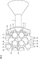
- FIG 2 there is shown, schematically, the volume of the fuel delivery passage 8 in which fuel can flow and which provides the reservoir of fuel that is supplied to the fuel injectors.
- Figure 2 can be considered to illustrate a positive representation of the negative or hollow portion of the main gallery 2 which provides the passage 8 without the main body 24 of the main gallery 2.
- the fuel in the inlet chamber 10 passes to a plurality of outlets 20 formed by pipe sections 14 forming a multiplicity of channels 12 into a single outlet port 6.
- the chambers 16 are substantially spheres and have a plurality of inlets 14a and a plurality of outlets 14b.
- a plurality of channels 12 are formed interlinked in places by pipes 14 to form a labyrinth from the inlet chamber 10 which ultimately leads to four channel outlets 20 each connected to an associated one of the outlet ports 6 leading to the injectors.
- the arrangement is not limited to four channel outlets 20 as illustrated in figure 2 .
- One or more channel outlet ports 20 may be connected to an associated one of the outlet port 6.
- the length of the various pipe sections 14 and the cross-sectional area, or diameter of volume of the various chambers 16 can be substantially the same or can vary.
- the position of the pipe section 14 and chamber 16 with respect to the outlet port 6 and/or with respect to the fuel inlet port 4 may determine its relative its dimensions. For example, chambers 16 which are located at a smaller distance from the outlet port 6 may be smaller than the chambers 16 which are located as a larger distance with respect to the same outlet port 6.
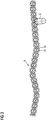
- Figure 3 illustrates a view of a fuel delivery passage 8 showing one outlet port 6 intermediate the length of the fuel delivery passage 8.
- the passage 8 is formed of a multiplicity of pipe sections 14 and spheres providing chambers 16 which are linked together by pipe sections 14 to perform a complex labyrinth defining at least one channel 12.
- Some spheres 16 have four openings 16a, 16b and may be connected to provide at least one inlet, the remainder being outlets 18 in the direction of the flow of fuel.
- Some spheres 16 may have fewer openings 16a, 16b, for example two openings, or more than four openings.
- the diameter of the spheres may vary.
- the enlarged sections of the passage 8 or chambers 16 need not be spherical but could be just an enlarged section of pipe of a predetermined length and the cross-sectional shape of the individual pipes and enlarged sections may be varied to provide the precise guidance to the fuel flow required. Similarly, certain sections may be formed with a reduced cross-sectional area as required by the desired flow pressure patterns through the passage.
- the main gallery 2 may be formed from a metal or alloy.
- the main gallery 2 with its fuel delivery passage 8 may be fabricated using additive manufacturing techniques.
- additive manufacturing a three-dimensional object is built up layer by layer in contrast to subtraction techniques in which a portion of a work piece is removed to form an object with the desired form.
- Additive manufacturing techniques may be conveniently used to produce a labyrinth of channels 14.
- An example of an additive manufacturing technique is 3D printing in which material is deposited suing a moving inkjet print head.
- a further example is powder bed fusion in which thermal energy from a laser of electron beam is used to selectively fuse powder in a powder bed.
- a further example is directed energy deposition in which thermal energy, for example from a laser, is used to fuse materials by melting them as they are deposited.
- the movement of the inkjet print head, laser or electron beam is computer controlled to build up an object, in this case the main body and the passage 8, layer by layer according to a three-dimensional model, such as a CAD (Computer Aided Design) model, of the main body and the passage 8.
- CAD Computer Aided Design
- the passage 8 may be fabricated using two or more preformed parts including one or more apertures that are joined with a fluid tight seal to produce a tortuous path.
- One or more of the preformed parts may include a variation in cross-sectional area along its length.
- the outer contour of the main gallery 2 has a diameter or outer contour that varies along its length.
- the main body 24 of the passage 8 may have localised thickness variations. For example, in regions which do not require such a high strength the wall thickness may be less that in regions which require a higher strength. This embodiment may be used to reduce the weight of the main gallery 2 and reduce material usage and/or to produce a localised increased strength.
Landscapes
- Engineering & Computer Science (AREA)
- Chemical & Material Sciences (AREA)
- Combustion & Propulsion (AREA)
- Mechanical Engineering (AREA)
- General Engineering & Computer Science (AREA)
- Fuel-Injection Apparatus (AREA)
Abstract
Description
- The present disclosure relates to a fuel delivery passage for a fuel injection system for an internal combustion engine. The disclosure relates, particularly but not exclusively, to a fuel delivery passage for incorporation in a main gallery of a fuel injection system for a multicylinder direct injection internal combustion engine.
- In known arrangements, the main gallery comprises an elongate reservoir for fuel in which the fuel is supplied by a high pressure fuel pump and outlets for supplying fuel to a fuel injector for directing fuel directly into each cylinder of the engine. The volume of fuel in the reservoir is intended to damp out fluctuations in the pressure of the fuel supplied by the pump so that the pressure at each outlet is equal and substantially constant.
- In the known arrangements, the main gallery is typically a substantial generally tubular element which has to be strong enough to cope with the stresses of the load applied to the main gallery by the high pressure of fuel in the reservoir. As a result, the main gallery tends to be heavy and costly because of the amount of material used in its construction.
- The present disclosure seeks to provide a fuel supply system which overcomes or mitigates the disadvantages of the known main galleries.
- The present disclosure shows a fuel delivery passage for a fuel injection system for an internal combustion engine, the passage including a fuel inlet adapted to receive fuel from a high-pressure source, and at least one fuel outlet adapted to be connected to an inlet port of a fuel injector. The passage comprises at least one channel having a tortuous path for the fuel flow. At least one section of the channel varies in cross-sectional area over a predetermined length of the channel.
- The main gallery or fuel rail has a fuel delivery passage that may be considered to have an alveolar design or structure. A tortuous path for the fuel flow has two or more deviations from a straight line and may have a winding form. The tortuous path for the flow of fuel provided by the channel in combination with the variation in cross-sectional area in at least one section of the channel provides a fuel delivery passage with which variations of the pressure of the fuel delivered to the fuel outlet and consequently to the fuel injector are reduced. The hydraulic behaviour of the fuel can be improved by use of an appropriately designed alveolar structure for the fuel delivery passage.
- The cross-sectional area may be increased or reduced for a predetermined length of the channel. The cross-sectional area may be increased or reduced for a predetermined length of the section of the channel compared to the cross-sectional area of the channel adjacent the section or compared to the cross-sectional area of the channel in an adjoining portion of the section. This form makes use of Bernoulli's principle that an increase in the cross-sectional area of a pipe causes a decrease in flow rate and an increase in pressure of a fluid flowing in the pipe and vice versa. Consequently, the pressure of the fuel can be locally increased or decreased by selection of an increased or decreased cross-sectional area of one or more sections of the channel or channels of the passage.
- The tortuous path for the flow of fuel may be provided by forming the channel such that at least one portion of the channel extends at an inclined angle to the entrance of the channel and/or to the exit of the channel provide a winding or twisting path for the fuel flow. The longest path of fluid through a curved pipe has the highest pressure and the lowest speed. The shortest path through the curve has the lowest pressure and the highest speed. In other words, when the path of a fluid in steady-state flow bends, the pressure on the outside of the bend is always higher than the pressure on the inside of the bend. The tortuous path provided by the channel provides a mechanism by which the pressure and speed of the fuel can be varied, also within the cross-sectional area of the channel.
- In some embodiments, a plurality of sections with a varying cross-sectional area are spaced along the length of the channel. This arrangement may be used to further locally control the pressure and flow rate of the fuel within the channel. The sections of the channel or channels may each have a different cross-sectional area and shape and length in the direction of flow of fuel.
- In some embodiments, the section comprises a chamber and a pipe section, the chamber having a larger cross-sectional area than the pipe section. The chamber may be substantially spherical, for example. Each chamber may include at least two openings, one connected to the pipe section and one connected to a further portion of the channel, for example a further pipe section. The pipe section may provide the inlet or outlet to the chamber. The openings may be arranged at an including angles to one another and provide a tortuous path for the fuel.
- In some embodiments, the chamber includes more than two openings and may have two or more inlets and two or more outlets. This arrangement may be used to provide two or more alternative paths for the fuel. This arrangement may also be used to provide two or more paths which extend in different directions and which have different effects on the pressure and flow rate of the fuel as well as the direction of flow of the fuel.
- The fuel delivery passage may deliver fuel to a single outlet, for example for an internal combustion engine having a single fuel injector. In some embodiments, the passage has a plurality of fuel outlets each being adapted to be connected to an associated inlet port of a fuel injector. The passage also includes at least one channel for each fuel outlet. In some embodiments, two or more channels extend into a fuel outlet. The pressure of the fuel in each channel may be different so that this arrangement may be used to deliver fuel to the fuel outlet with a spatially locally variable pressure or at a pressure averaged over the pressure delivered by each channel.
- In some embodiments, the passage comprises a plurality of said channels that are interconnected at predetermined points and form a labyrinth of channels. The labyrinth of channels provides a single passage with which the pressure and flow rate of the fuel locally varies as a result of the tortuous or bending paths provided by the labyrinth and as a result of the local variation in the cross-section of the channels. The labyrinth of channels provides a plurality of fuel delivery paths from the fuel inlet to an output port of a channel associated with a fuel outlet. The number of channels may also be selected in order to optimise the hydraulic behaviour of the fuel delivery passage.
- The shape of the channels and the overall passage may be arranged to damp out fluctuations in the flow and pressure of fuel to ensure that the pressure of fuel at each outlet is at the required level and with the minimal variation in the actual pressure.
- In an embodiment, a main gallery is provided that comprises a fuel delivery passage according to any one of the embodiments described above. The main gallery may include a main body or structural body that provides the passage. In some embodiments, the main gallery may include a massive part whereby the channel or channels providing the passage are formed in the massive part such that the outer contour of the main gallery differs from the outer contour of the passage. In some embodiments, the main body is provided by support walls having an outer contour which substantially corresponds to the outer contour of the passage. In some embodiments, the main body includes a variable wall thickness such that the strength of the main body can be locally varied. For example, an area of the main body which is to have a higher strength or robustness, for example an area that supports a fixture, may have an increased wall thickness compared to an area of the main body which may have a lower strength.
- In an embodiment, a fuel rail assembly comprising a main gallery according to one of the embodiments described herein is provided. The fuel rail assembly may also include one or more fuel outlets in fluid communication with the passage and one or more fixtures for mounting the fuel rail assembly to a vehicle, for example an engine block of the vehicle.
- A method of fabricating a main gallery of a fuel delivery system for an internal combustion engine is provided, the method comprising building up a main body having a fuel delivery passage according to any one of the embodiments described herein layer by layer.
- Additive manufacturing techniques may be used to build up the main body layer by layer. For example, the main body may be built up layer by layer using 3D (Three-dimensional) printing or Powder Bed Fusion or Directed Energy Deposition. The main body may be built up layer by layer by movement of the inkjet print head, laser or electron beam controlled according to a three dimensional model of the main body having the fuel delivery passage.
- Embodiments of the present disclosure will now be described by way of example with reference to the accompanying schematic drawings, in which:
- Figure 1
- illustrates a cross-sectional view through a schematic arrangement of a main gallery with a fuel delivery passage,
- Figure 2
- illustrates a view of the fuel delivery passage fluid domain and fuel inlet, and
- Figure 3
- illustrates the complete fuel rail length of a fuel delivery passage fluid domain containing a multiplicity of channels.
-
Figure 1 discloses a cross-section through a schematic arrangement of a main gallery 2 for a fuel injection system of a direct injection internal combustion engine. The main gallery 2 provides a reservoir for fuel which is supplied to the fuel injectors. -
Figure 1 illustrates a portion of a main gallery 2 having afuel inlet port 4 adapted to be connected to a high pressure pump (not shown) through which fuel is supplied to the main gallery 2. The main gallery 2 has one ormore outlet ports 6 adapted to receive an inlet port of a fuel injector (not shown). - The main gallery 2 has a fuel delivery passage 8 which provides a reservoir of fuel for the fuel injector or injectors. The fuel delivery passage 8 is formed so as to provide a multiplicity of
channels 12. At least one of thechannels 12 provides a tortuous path for the fuel. In other words, the path for the fuel provided by thechannel 12 has two or more deviations from a straight line and may have a winding form. At least some of thechannels 12 of the fuel delivery passage 8 are in fluid communication and provide a labyrinth passage having a plurality ofpossible paths 22 for the flow of fuel. - The fuel delivery passage 8 comprises an
inlet chamber 10 adjacent theinlet port 4 which leads to the multiplicity ofchannels 12, of which some lead into one of theoutlet ports 6. In the cross-sectional view offigure 1 , fourchannel outlets 12 are in fluid communication with theinlet port 4 and twochannels 12 are in fluid communication with theoutlet port 6. However, the number ofchannels 12 in fluid communication with theinlet port 4 andoutlet port 6 is not limited to four and two, respectively, and may vary. - The
channels 12 of the fuel delivery passage 8 provide a labyrinth passage which has a variable cross-section along its length. In the particular example illustrated infigure 1 , the channels comprisepipe sections 14 leading to enlargedportions providing chambers 16 having a cross-sectional area that is greater than that of theadjacent pipe sections 14. In this particular embodiment, the enlarged portions providing thechambers 16 are substantially spherical. - Each of the
chambers 16 includes at least twoopenings potential outlets 18 extending in predetermined directions into afurther pipe section 14 which continues thechannel 12 of the passage 8. Theopenings chamber 16 so as to provide a bent path for the flow of fuel and together withfurther chambers 16 andpipe sections 14 atortuous path 22 for the fuel. - The
pipe sections 14 andchambers 16 can be connected to form a convoluted labyrinth for the channel orchannels 12 which finally leads to theoutput port 6. Thetortuous path 22 provided by the convoluted labyrinth and changes in the cross-sectional area of thechannel 12 provided by thechambers 16 damp out pressure fluctuations of the fuel from the fuel pump and serve to ensure that the fuel arriving at theoutlet port 6 is at the desired pressure and has a minimal variational fluctuation in the flow and/or pressure. - In some embodiments, fuel supplied to the
outlet port 6 may take one of a number ofdifferent paths 22 through the labyrinth passage 8 due to the connections between thechannels 12. - Referring now to
figure 2 , there is shown, schematically, the volume of the fuel delivery passage 8 in which fuel can flow and which provides the reservoir of fuel that is supplied to the fuel injectors.Figure 2 can be considered to illustrate a positive representation of the negative or hollow portion of the main gallery 2 which provides the passage 8 without themain body 24 of the main gallery 2. In this particular arrangement, it can be seen that the fuel in theinlet chamber 10 passes to a plurality ofoutlets 20 formed bypipe sections 14 forming a multiplicity ofchannels 12 into asingle outlet port 6. In this arrangement, thechambers 16 are substantially spheres and have a plurality ofinlets 14a and a plurality ofoutlets 14b. In this way, a plurality ofchannels 12 are formed interlinked in places bypipes 14 to form a labyrinth from theinlet chamber 10 which ultimately leads to fourchannel outlets 20 each connected to an associated one of theoutlet ports 6 leading to the injectors. - However, the arrangement is not limited to four
channel outlets 20 as illustrated infigure 2 . One or morechannel outlet ports 20 may be connected to an associated one of theoutlet port 6. The length of thevarious pipe sections 14 and the cross-sectional area, or diameter of volume of thevarious chambers 16 can be substantially the same or can vary. In some embodiments, the position of thepipe section 14 andchamber 16 with respect to theoutlet port 6 and/or with respect to thefuel inlet port 4 may determine its relative its dimensions. For example,chambers 16 which are located at a smaller distance from theoutlet port 6 may be smaller than thechambers 16 which are located as a larger distance with respect to thesame outlet port 6. -
Figure 3 illustrates a view of a fuel delivery passage 8 showing oneoutlet port 6 intermediate the length of the fuel delivery passage 8. The passage 8 is formed of a multiplicity ofpipe sections 14 andspheres providing chambers 16 which are linked together bypipe sections 14 to perform a complex labyrinth defining at least onechannel 12. Somespheres 16 have fouropenings remainder being outlets 18 in the direction of the flow of fuel. Somespheres 16 may havefewer openings - Although described as
spheres 16 andpipe sections 14, it will be understood that the enlarged sections of the passage 8 orchambers 16 need not be spherical but could be just an enlarged section of pipe of a predetermined length and the cross-sectional shape of the individual pipes and enlarged sections may be varied to provide the precise guidance to the fuel flow required. Similarly, certain sections may be formed with a reduced cross-sectional area as required by the desired flow pressure patterns through the passage. - The main gallery 2 may be formed from a metal or alloy. The main gallery 2 with its fuel delivery passage 8 may be fabricated using additive manufacturing techniques. In additive manufacturing, a three-dimensional object is built up layer by layer in contrast to subtraction techniques in which a portion of a work piece is removed to form an object with the desired form. Additive manufacturing techniques may be conveniently used to produce a labyrinth of
channels 14. - An example of an additive manufacturing technique is 3D printing in which material is deposited suing a moving inkjet print head. A further example is powder bed fusion in which thermal energy from a laser of electron beam is used to selectively fuse powder in a powder bed. A further example is directed energy deposition in which thermal energy, for example from a laser, is used to fuse materials by melting them as they are deposited. The movement of the inkjet print head, laser or electron beam is computer controlled to build up an object, in this case the main body and the passage 8, layer by layer according to a three-dimensional model, such as a CAD (Computer Aided Design) model, of the main body and the passage 8.
- In some embodiments, the passage 8 may be fabricated using two or more preformed parts including one or more apertures that are joined with a fluid tight seal to produce a tortuous path. One or more of the preformed parts may include a variation in cross-sectional area along its length.
- In some embodiments, the outer contour of the main gallery 2 has a diameter or outer contour that varies along its length. For example, the
main body 24 of the passage 8 may have localised thickness variations. For example, in regions which do not require such a high strength the wall thickness may be less that in regions which require a higher strength. This embodiment may be used to reduce the weight of the main gallery 2 and reduce material usage and/or to produce a localised increased strength.
Claims (16)
- A fuel delivery passage (8) for a fuel injection system for an internal combustion engine, the passage (8) including a fuel inlet (4) adapted to receive fuel from a high-pressure source, and at least one fuel outlet (6) adapted to be connected to an inlet port of a fuel injector,
wherein the passage (8) comprises at least one channel (12) having a tortuous path (22) for the fuel flow and at least one section (16) of the channel (12) varies in cross-sectional area over a predetermined length. - A fuel delivery passage (8) according to claim 1, wherein the cross-sectional area is increased or reduced for a predetermined length of the channel (12).
- A fuel delivery passage (8) according to claim 1 or 2, wherein a plurality of said sections (16) are spaced along the length of the channel (12).
- A fuel delivery passage (8) according to claim 3, wherein the sections (16) each have a different cross-sectional area and shape and length in the direction of flow of fuel.
- A fuel delivery passage (8) according to any one of the preceding claims, wherein the section comprises a chamber (16) and a pipe section (14), the chamber (16) having a larger cross-sectional area than the pipe section (14).
- A fuel delivery passage (8) according to any one of the preceding claims, wherein the chamber (16) is substantially spherical.
- A fuel delivery passage (8) according to any one of the preceding claims, wherein the passage (8) has a plurality of fuel outlets (6) each being adapted to be connected to an associated inlet port of a fuel injector and at least one channel (12) for each fuel outlet (6).
- A fuel delivery passage (8) according to claim 7, wherein two or more channels (12) extend to a fuel outlet (6).
- A fuel delivery passage (8) according to any one of the preceding claims, wherein the passage (8) comprises a plurality of said channels (12) that are interconnected at predetermined points and form a labyrinth of channels.
- A fuel delivery passage (8) according to claim 9, wherein the labyrinth of channels (12) provides a plurality of fuel delivery paths (22) from the fuel inlet (4) to an output port (20) of a channel (12) associated with a fuel outlet (6).
- A fuel delivery passage (8) according to any one of the preceding claims, wherein the shape of the channels (12) and the overall passage (8) are arranged to damp out fluctuations in the flow and pressure of fuel to ensure that the pressure of fuel at each outlet (6) is at the required level and with the minimal variation in the actual pressure.
- A main gallery (2) comprising a fuel delivery passage (8) according to any one of claims 1 to 11.
- A fuel rail assembly comprising a main gallery (2) according to claim 12.
- A method of fabricating a main gallery (2) of a fuel delivery system for an internal combustion engine, comprising:building up a main body (24) having a fuel delivery passage (8) according to any one of claims 1 to 10 layer by layer.
- A method according to claim 13, wherein the main body (24) is built up layer by layer by 3D printing or Powder Bed Fusion or Directed Energy Deposition.
- A method according to claim 13 or claim 14, wherein the main body (24) is built up layer by layer by movement of the inkjet print head, laser or electron beam controlled according to a three dimensional model of the main body (24) having the fuel delivery passage (8).
Priority Applications (1)
| Application Number | Priority Date | Filing Date | Title |
|---|---|---|---|
| EP17208810.6A EP3502461A1 (en) | 2017-12-20 | 2017-12-20 | A fuel delivery passage for a fuel injection system and a method of manufacturing a fuel delivery passage |
Applications Claiming Priority (1)
| Application Number | Priority Date | Filing Date | Title |
|---|---|---|---|
| EP17208810.6A EP3502461A1 (en) | 2017-12-20 | 2017-12-20 | A fuel delivery passage for a fuel injection system and a method of manufacturing a fuel delivery passage |
Publications (1)
| Publication Number | Publication Date |
|---|---|
| EP3502461A1 true EP3502461A1 (en) | 2019-06-26 |
Family
ID=60702328
Family Applications (1)
| Application Number | Title | Priority Date | Filing Date |
|---|---|---|---|
| EP17208810.6A Ceased EP3502461A1 (en) | 2017-12-20 | 2017-12-20 | A fuel delivery passage for a fuel injection system and a method of manufacturing a fuel delivery passage |
Country Status (1)
| Country | Link |
|---|---|
| EP (1) | EP3502461A1 (en) |
Cited By (1)
| Publication number | Priority date | Publication date | Assignee | Title |
|---|---|---|---|---|
| EP3805547A1 (en) * | 2019-10-08 | 2021-04-14 | Vitesco Technologies GmbH | Fuel injection assembly and method of manufacturing a fuel rail assembly |
Citations (4)
| Publication number | Priority date | Publication date | Assignee | Title |
|---|---|---|---|---|
| WO2004036029A1 (en) * | 2002-10-14 | 2004-04-29 | Siemens Aktiengesellschaft | Accumulator injection system for damping pressure waves, especially in a common rail injection system |
| EP2466112A2 (en) * | 2010-12-15 | 2012-06-20 | KW Technologie GmbH & Co. KG | Pulsation dampener |
| EP2639442A1 (en) * | 2012-03-15 | 2013-09-18 | Akademia Morska W Szczecinie | Fuel injector |
| US20160175928A1 (en) * | 2014-12-19 | 2016-06-23 | Maynard Steel Casting Company | Steel foam and method for manufacturing steel foam |
-
2017
- 2017-12-20 EP EP17208810.6A patent/EP3502461A1/en not_active Ceased
Patent Citations (4)
| Publication number | Priority date | Publication date | Assignee | Title |
|---|---|---|---|---|
| WO2004036029A1 (en) * | 2002-10-14 | 2004-04-29 | Siemens Aktiengesellschaft | Accumulator injection system for damping pressure waves, especially in a common rail injection system |
| EP2466112A2 (en) * | 2010-12-15 | 2012-06-20 | KW Technologie GmbH & Co. KG | Pulsation dampener |
| EP2639442A1 (en) * | 2012-03-15 | 2013-09-18 | Akademia Morska W Szczecinie | Fuel injector |
| US20160175928A1 (en) * | 2014-12-19 | 2016-06-23 | Maynard Steel Casting Company | Steel foam and method for manufacturing steel foam |
Cited By (1)
| Publication number | Priority date | Publication date | Assignee | Title |
|---|---|---|---|---|
| EP3805547A1 (en) * | 2019-10-08 | 2021-04-14 | Vitesco Technologies GmbH | Fuel injection assembly and method of manufacturing a fuel rail assembly |
Similar Documents
| Publication | Publication Date | Title |
|---|---|---|
| US10539252B2 (en) | Aerodynamic noise reduction cage | |
| US11608841B2 (en) | Housing block, method for producing a housing block, and core | |
| RU2754835C2 (en) | Anti-cavitation element for use with valves | |
| CA2992318A1 (en) | Jet pump manufactured using additive and subtractive machining techniques | |
| CN113039352A (en) | Composite fuel manifold | |
| US11454390B2 (en) | Spray heads for use with desuperheaters and desuperheaters including such spray heads | |
| EP3658808A1 (en) | Improved noise attenuation trim assembly | |
| US11767973B2 (en) | Spray heads for use with desuperheaters and desuperheaters including such spray heads | |
| WO2018005106A1 (en) | Integral fluid conduit | |
| CA3031657A1 (en) | Thermal insulation for fluid carrying components | |
| EP3604787B1 (en) | Fuel rail for a fuel injection system and method of manufacturing such a fuel rail | |
| CN110043386A (en) | The fluid delivery ports of integrated cylinder cover | |
| EP3670895B1 (en) | Fuel rail assembly for a fuel injection system for an internal combustion engine | |
| EP3636912A1 (en) | Fuel rail for a fuel injection system for an internal combustion engine and method for manufacturing a fuel rail | |
| EP3805547A1 (en) | Fuel injection assembly and method of manufacturing a fuel rail assembly | |
| EP3617492A1 (en) | A fuel rail for a fuel injection system for an internal combustion engine and a method for manufacturing a fuel rail | |
| US20230323903A1 (en) | Tunable, Pulsatile, and 3-Dimensional Fluidic Oscillator | |
| KR20240007759A (en) | Fluid sprayer for powertrain and method of manufacturing same | |
| EP3078828B1 (en) | Internal combustion engine and manufacturing method thereof | |
| US10858982B2 (en) | Piston cooling system | |
| CN106438052A (en) | Fuel injector device |
Legal Events
| Date | Code | Title | Description |
|---|---|---|---|
| PUAI | Public reference made under article 153(3) epc to a published international application that has entered the european phase |
Free format text: ORIGINAL CODE: 0009012 |
|
| STAA | Information on the status of an ep patent application or granted ep patent |
Free format text: STATUS: THE APPLICATION HAS BEEN PUBLISHED |
|
| AK | Designated contracting states |
Kind code of ref document: A1 Designated state(s): AL AT BE BG CH CY CZ DE DK EE ES FI FR GB GR HR HU IE IS IT LI LT LU LV MC MK MT NL NO PL PT RO RS SE SI SK SM TR |
|
| AX | Request for extension of the european patent |
Extension state: BA ME |
|
| STAA | Information on the status of an ep patent application or granted ep patent |
Free format text: STATUS: REQUEST FOR EXAMINATION WAS MADE |
|
| 17P | Request for examination filed |
Effective date: 20200102 |
|
| RBV | Designated contracting states (corrected) |
Designated state(s): AL AT BE BG CH CY CZ DE DK EE ES FI FR GB GR HR HU IE IS IT LI LT LU LV MC MK MT NL NO PL PT RO RS SE SI SK SM TR |
|
| RAP1 | Party data changed (applicant data changed or rights of an application transferred) |
Owner name: VITESCO TECHNOLOGIES GMBH |
|
| STAA | Information on the status of an ep patent application or granted ep patent |
Free format text: STATUS: EXAMINATION IS IN PROGRESS |
|
| 17Q | First examination report despatched |
Effective date: 20200615 |
|
| RAP3 | Party data changed (applicant data changed or rights of an application transferred) |
Owner name: VITESCO TECHNOLOGIES GMBH |
|
| STAA | Information on the status of an ep patent application or granted ep patent |
Free format text: STATUS: THE APPLICATION HAS BEEN REFUSED |
|
| 18R | Application refused |
Effective date: 20220113 |