EP3502449A1 - Intake structure of internal combustion engine - Google Patents
Intake structure of internal combustion engine Download PDFInfo
- Publication number
- EP3502449A1 EP3502449A1 EP18211449.6A EP18211449A EP3502449A1 EP 3502449 A1 EP3502449 A1 EP 3502449A1 EP 18211449 A EP18211449 A EP 18211449A EP 3502449 A1 EP3502449 A1 EP 3502449A1
- Authority
- EP
- European Patent Office
- Prior art keywords
- intake
- cylinder chamber
- convex portion
- apex
- intake port
- Prior art date
- Legal status (The legal status is an assumption and is not a legal conclusion. Google has not performed a legal analysis and makes no representation as to the accuracy of the status listed.)
- Granted
Links
Images



Classifications
-
- F—MECHANICAL ENGINEERING; LIGHTING; HEATING; WEAPONS; BLASTING
- F02—COMBUSTION ENGINES; HOT-GAS OR COMBUSTION-PRODUCT ENGINE PLANTS
- F02B—INTERNAL-COMBUSTION PISTON ENGINES; COMBUSTION ENGINES IN GENERAL
- F02B31/00—Modifying induction systems for imparting a rotation to the charge in the cylinder
-
- F—MECHANICAL ENGINEERING; LIGHTING; HEATING; WEAPONS; BLASTING
- F02—COMBUSTION ENGINES; HOT-GAS OR COMBUSTION-PRODUCT ENGINE PLANTS
- F02B—INTERNAL-COMBUSTION PISTON ENGINES; COMBUSTION ENGINES IN GENERAL
- F02B23/00—Other engines characterised by special shape or construction of combustion chambers to improve operation
- F02B23/08—Other engines characterised by special shape or construction of combustion chambers to improve operation with positive ignition
- F02B23/10—Other engines characterised by special shape or construction of combustion chambers to improve operation with positive ignition with separate admission of air and fuel into cylinder
-
- F—MECHANICAL ENGINEERING; LIGHTING; HEATING; WEAPONS; BLASTING
- F02—COMBUSTION ENGINES; HOT-GAS OR COMBUSTION-PRODUCT ENGINE PLANTS
- F02B—INTERNAL-COMBUSTION PISTON ENGINES; COMBUSTION ENGINES IN GENERAL
- F02B31/00—Modifying induction systems for imparting a rotation to the charge in the cylinder
- F02B31/04—Modifying induction systems for imparting a rotation to the charge in the cylinder by means within the induction channel, e.g. deflectors
-
- F—MECHANICAL ENGINEERING; LIGHTING; HEATING; WEAPONS; BLASTING
- F02—COMBUSTION ENGINES; HOT-GAS OR COMBUSTION-PRODUCT ENGINE PLANTS
- F02F—CYLINDERS, PISTONS OR CASINGS, FOR COMBUSTION ENGINES; ARRANGEMENTS OF SEALINGS IN COMBUSTION ENGINES
- F02F1/00—Cylinders; Cylinder heads
- F02F1/24—Cylinder heads
- F02F1/42—Shape or arrangement of intake or exhaust channels in cylinder heads
- F02F1/4214—Shape or arrangement of intake or exhaust channels in cylinder heads specially adapted for four or more valves per cylinder
-
- F—MECHANICAL ENGINEERING; LIGHTING; HEATING; WEAPONS; BLASTING
- F02—COMBUSTION ENGINES; HOT-GAS OR COMBUSTION-PRODUCT ENGINE PLANTS
- F02F—CYLINDERS, PISTONS OR CASINGS, FOR COMBUSTION ENGINES; ARRANGEMENTS OF SEALINGS IN COMBUSTION ENGINES
- F02F1/00—Cylinders; Cylinder heads
- F02F1/24—Cylinder heads
- F02F1/42—Shape or arrangement of intake or exhaust channels in cylinder heads
- F02F1/4235—Shape or arrangement of intake or exhaust channels in cylinder heads of intake channels
-
- F—MECHANICAL ENGINEERING; LIGHTING; HEATING; WEAPONS; BLASTING
- F02—COMBUSTION ENGINES; HOT-GAS OR COMBUSTION-PRODUCT ENGINE PLANTS
- F02F—CYLINDERS, PISTONS OR CASINGS, FOR COMBUSTION ENGINES; ARRANGEMENTS OF SEALINGS IN COMBUSTION ENGINES
- F02F1/00—Cylinders; Cylinder heads
- F02F1/24—Cylinder heads
- F02F1/42—Shape or arrangement of intake or exhaust channels in cylinder heads
- F02F1/4235—Shape or arrangement of intake or exhaust channels in cylinder heads of intake channels
- F02F1/425—Shape or arrangement of intake or exhaust channels in cylinder heads of intake channels with a separate deviation element inside the channel
-
- F—MECHANICAL ENGINEERING; LIGHTING; HEATING; WEAPONS; BLASTING
- F02—COMBUSTION ENGINES; HOT-GAS OR COMBUSTION-PRODUCT ENGINE PLANTS
- F02M—SUPPLYING COMBUSTION ENGINES IN GENERAL WITH COMBUSTIBLE MIXTURES OR CONSTITUENTS THEREOF
- F02M35/00—Combustion-air cleaners, air intakes, intake silencers, or induction systems specially adapted for, or arranged on, internal-combustion engines
- F02M35/10—Air intakes; Induction systems
- F02M35/10091—Air intakes; Induction systems characterised by details of intake ducts: shapes; connections; arrangements
- F02M35/10118—Air intakes; Induction systems characterised by details of intake ducts: shapes; connections; arrangements with variable cross-sections of intake ducts along their length; Venturis; Diffusers
-
- F—MECHANICAL ENGINEERING; LIGHTING; HEATING; WEAPONS; BLASTING
- F02—COMBUSTION ENGINES; HOT-GAS OR COMBUSTION-PRODUCT ENGINE PLANTS
- F02B—INTERNAL-COMBUSTION PISTON ENGINES; COMBUSTION ENGINES IN GENERAL
- F02B23/00—Other engines characterised by special shape or construction of combustion chambers to improve operation
- F02B23/08—Other engines characterised by special shape or construction of combustion chambers to improve operation with positive ignition
- F02B23/10—Other engines characterised by special shape or construction of combustion chambers to improve operation with positive ignition with separate admission of air and fuel into cylinder
- F02B2023/106—Tumble flow, i.e. the axis of rotation of the main charge flow motion is horizontal
-
- Y—GENERAL TAGGING OF NEW TECHNOLOGICAL DEVELOPMENTS; GENERAL TAGGING OF CROSS-SECTIONAL TECHNOLOGIES SPANNING OVER SEVERAL SECTIONS OF THE IPC; TECHNICAL SUBJECTS COVERED BY FORMER USPC CROSS-REFERENCE ART COLLECTIONS [XRACs] AND DIGESTS
- Y02—TECHNOLOGIES OR APPLICATIONS FOR MITIGATION OR ADAPTATION AGAINST CLIMATE CHANGE
- Y02T—CLIMATE CHANGE MITIGATION TECHNOLOGIES RELATED TO TRANSPORTATION
- Y02T10/00—Road transport of goods or passengers
- Y02T10/10—Internal combustion engine [ICE] based vehicles
- Y02T10/12—Improving ICE efficiencies
Definitions
- the present invention relates to an intake structure of an internal combustion engine.
- an intake port is provided to be inclined to one side of a cylinder chamber with respect to the center line of the cylinder chamber, so as to form the tumble flow.
- JP-U-H7-25235 it is proposed that a protrusion part which generates a deflection flow for generating a tumble flow is provided in the intake port, and the protrusion part is formed of an elastic bellows.
- the strength of the deflection flow is adjusted by adjusting the swelling amount of the protrusion part, so that the strength of the tumble flow is adjusted according to the load of the internal combustion engine.
- JP-A-2004-316609 it is proposed that a stepped part which projects to the inside of the intake port is provided in a boundary between a wall surface positioned on the far side from the one side of wall surfaces of the intake port and a throat part of a valve seat continuous to the intake port.
- the flow of the intake air guided along the wall surface positioned on the far side from the one side of the wall surfaces of the intake port, that is, the intake air in a direction opposite to the tumble flow is disturbed by the stepped part.
- the flow rate of the intake air guided in the cylinder chamber on the side opposite to the one side, that is, the intake air in the direction opposite to the tumble flow is controlled to obtain a strong tumble flow.
- a cylinder head forms the valve seat or the like in a casting by machining.
- the position of the stepped part is varied according to a processing accuracy, and the variation occurs to the height of the stepped part when a deviation of a mold at the time of casting is repeated.
- the invention has been made in consideration of the above situation, and an object thereof is to provide an intake structure of an internal combustion engine which is advantageous for strengthening a tumble flow in a cylinder chamber and preventing a backflow of a fuel-air mixture to an intake port.
- a convex portion in an intake structure of an internal combustion engine, on an intake upstream side from a valve seat of an intake port, a convex portion is provided which protrudes to an inside of the intake port in a place near an outer circumferential portion of a cylinder chamber when viewed from an upper side of the cylinder chamber.
- the convex portion includes an upstream guide surface extending from an apex of the convex portion to the intake upstream side, and a downstream guide surface extending from the apex to an intake downstream side and including a curved surface recessed inside the convex portion at a middle portion thereof.
- the downstream guide surface guides the fuel-air mixture, which is guided by the tumble flow from the cylinder chamber to the outer circumferential wall part about to return to the intake port, from the outer circumferential wall part to the central wall part.
- the fuel-air mixture which is about to return from the cylinder chamber to the upstream side of the intake port by the tumble flow, is blocked by the flow of the guided fuel-air mixture.
- an internal combustion engine (engine) 10 includes a cylinder block 14 in which a plurality of cylinder chambers 12 are formed, a cylinder head 16 which is provided on the upper side of the cylinder block 14, and a piston 18 which is arranged in the cylinder chamber 12.
- a combustion chamber 20 is configured by an inner circumferential surface 1202 of the cylinder chamber 12, a lower surface 1602 of the cylinder head 16, and a top surface 1802 of the piston 18.
- the cylinder head 16 is provided with two intake ports 22, intake valves 24 which open and close the respective intake ports 22, two exhaust ports 26, exhaust valves 28 which open and close the respective exhaust ports 26, and an ignition plug 30.
- the ignition plug 30 is provided in the lower surface 1602 of the cylinder head 16 to be positioned at the almost center of the combustion chamber 20.
- Each of the intake ports 22 includes an upstream portion 2202 which communicates with an intake manifold 31 to extend on the upper side of the cylinder chamber 12 in the radial direction of the cylinder chamber 12, and a downstream portion 2204 which is connected to the upstream portion 2202 and is curved to the cylinder chamber 12 side.
- An intake valve seat 32 is mounted in the downstream end of the downstream portion 2204, and the intake port 22 is closed and opened by contacting and separating the intake valve 24 on and from the intake valve seat 32.
- a portion 34 which is adjacent to the upstream side with respect to the intake valve seat 32, of the downstream portion 2204 includes a central wall part 34A which extends on the central portion side of the cylinder chamber 12 in a semi-arc shape and an outer circumferential wall part 34B which extends on the outer circumferential side of the cylinder chamber 12 in a semi-arc shape.
- a convex portion 36 for generating a tumble flow T1 is respectively formed to protrude to the inside of the intake port 22.
- a reference numeral 3610 denotes the apex of the convex portion 36.
- each convex portion 36 includes an upstream guide surface 3602 and a downstream guide surface 3604 respectively.
- the upstream guide surface 3602 extends from the apex 3610 to an intake upstream side.
- the downstream guide surface 3604 extends from the apex 3610 to the intake downstream side to form a curved surface recessed inside the convex portion 36 at a middle portion.
- the apex 3610 linearly extends in a direction orthogonal to the flow direction of the intake air of the intake port 22 when viewed from the upstream side of the intake air inside the intake port 22.
- the upstream guide surface 3602 is formed slantingly such that the intake air which flows in the cylinder chamber 12 from the intake port 22 forms the tumble flow T1.
- the upstream guide surface 3602 is formed such that the intake air which flows through the intake port 22 is directed to the center of the cylinder chamber 12.
- the upstream guide surface 3602 is continuously connected with the wall surface of the intake port 22 to form an obtuse angle.
- the downstream guide surface 3604 guides the fuel-air mixture, which is guided by the tumble flow T1 from the cylinder chamber 12 to the outer circumferential wall part 34B about to return to the intake port 22, to the central wall part 34A, thereby preventing that the fuel-air mixture returns to the upstream side of the intake port 22.
- the tip of the downstream guide surface 3604 is directed toward the portion of the central wall part 34A which extends on the central portion side of the cylinder chamber 12 in a semi-arc shape.
- the apex 3610 is formed in a streamline in which the upstream guide surface 3602 and the downstream guide surface 3604 are connected in a curved line.
- the convex portion 36 is formed by a mold, the apex 3610 and the upstream guide surface 3602 are formed in a core (mold), and the downstream guide surface 3604 is formed by cutting processing.
- the convex portion 36 can be produced simply, which is advantageous for improving the productivity.
- the apex 3610 of the convex portion 36 is formed by the cutting processing.
- the position of the apex 3610 may be deviated according to the accuracy of the cutting processing.
- the cutting processing is performed by a drill or the like, it is considered that the apex 3610 cannot be formed linearly, and the timing when the intake air is directed to the center of the cylinder chamber 12 is deviated in the radial direction, so as to affect the formation of the tumble flow T1.
- the end surface of the cutting processing is edged, it is also considered that a turbulence is generated by the edge, and the formation of the tumble flow T1 is also affected by the turbulence.
- the apex 3610 can be formed in a streamline which is connected in the curved line. Further, the edge made by the cutting processing is on the downstream side of the apex 3610, and thus the effect of the edge to the formation of the tumble flow can be reduced.
- the downstream guide surface 3604 guides the fuel-air mixture, which is guided by the tumble flow T1 from the cylinder chamber 12 to the outer circumferential wall part 34B about to return to the intake port 22, from the outer circumferential wall part 34B to the central wall part 34A.
- the intake air which is about to return from the cylinder chamber 12 to the upstream side of the intake port 22 by the tumble flow T1 is blocked by the flow T2 of the guided fuel-air mixture.
- the apex 3610 extends linearly in a direction orthogonal to the flow direction of the intake air of the intake port 22.
- the intake air is guided into the cylinder chamber 12 by the upstream guide surface 3602 of the convex portion 36 to form the tumble flow T1
- the intake air which is guided by the upstream guide surface 3602 of the convex portion 36 is not deflected in the extending direction of the apex 3610. Therefore, it is possible to strengthen the tumble flow T1, it is advantageous for guiding the intake air into the cylinder chamber 12 efficiently, and it is advantageous for improving the charging efficiency.
- the upstream guide surface 3602 and the wall surface of the intake port 22 are continuously connected to form an obtuse angle.
- the resistance due to the upstream guide surface 3602 is controlled while the intake air is deflected by the upstream guide surface 3602 to strengthen the tumble flow T1. It is advantageous for guiding the intake air into the cylinder chamber 12 efficiently, and it is advantageous for improving the charging efficiency.
- the downstream guide surface 3604 may be formed such that the fuel-air mixture, which is guided by the tumble flow T1 from the cylinder chamber 12 to the outer circumferential wall part 34B about to return to the intake port 22, is directed from the outer circumferential wall part 34B to a back surface 2404 of the intake valve 24 which faces the outer circumferential wall part 34B, so that a swirl flow is formed between the downstream guide surface 3604 and the back surface 2404 of the intake valve 24.
- the intake air which is about to return from the cylinder chamber 12 to the upstream side of the intake port 22 by the tumble flow T1 is blocked by the swirl flow.
- the second embodiment is different from the first embodiment in that the convex portion 36 includes two apexes 3610A and 3610B which have different protruding heights, and the second embodiment is similar to the first embodiment in that the upstream guide surface 3602 and the downstream guide surface 3604 are formed in each of the convex portions 36.
- the convex portion 36 when viewed from the upstream side of the intake port 22, the convex portion 36 includes a first portion 36A in which the apex 3610A extends linearly and a second portion 36B in which the apex 3610B with a smaller protruding amount than the apex 3610A extends linearly.
- Each of the apexes 3610A and 3610B extends in a direction orthogonal to the flow direction of the intake air which flows through the intake port 22.
- the first portions 36A are formed at places, which are apart from each other, of the convex portions 36.
- the apexes 3610A and 3610B of the convex portions 36A and 36B are formed such that the inside is lower than the outside, and the shape of the convex portions 36A and 36B is formed to be a linearly symmetrical shape having a center between the intake ports 22 when viewed from the upper side of the cylinder chamber 12.
- the second portions 36B which have smaller protruding amount than the first portion 36A are formed at places, which are near the center of the cylinder chamber 12, of the convex portions 36 in two intake ports 22.
- the tumble flow T1 whch is directed to the center (deep portion) of the cylinder chamber 12.
Landscapes
- Engineering & Computer Science (AREA)
- Chemical & Material Sciences (AREA)
- Combustion & Propulsion (AREA)
- Mechanical Engineering (AREA)
- General Engineering & Computer Science (AREA)
- Cylinder Crankcases Of Internal Combustion Engines (AREA)
- Combustion Methods Of Internal-Combustion Engines (AREA)
Abstract
Description
- The present invention relates to an intake structure of an internal combustion engine.
- There is known a technique in which a tumble flow swirling along an axis direction of a sylinder chamber is formed by intake air in order to perform combustion of an internal combustion engine efficiently.
- In that case, an intake port is provided to be inclined to one side of a cylinder chamber with respect to the center line of the cylinder chamber, so as to form the tumble flow.
- In order to improve the efficiency of the combustion of the internal combustion engine, it is important to obtain a strong tumble flow stably.
- In
JP-U-H7-25235 - According to
JP-U-H7-25235 - In
JP-A-2004-316609 - According to
JP-A-2004-316609 - However, in the related art, it is not considered how to prevent the partial backflow of the tumble flow formed in the cylinder chamber to the intake port.
- Particularly, when the internal combustion engine is operated with a high expansion ratio, in a case where the intake valve is closed late at the timing when a piston rises from a bottom dead center to a top dead center, the fuel-air mixture in the cylinder chamber more easily flows back to the intake port as the tumble flow is stronger. For this reason, there is a concern that a charging efficiency is deteriorated. In addition, generally, a cylinder head forms the valve seat or the like in a casting by machining. However, for example, in a case where the stepped part is formed by using the machine processing, there is a concern that the position of the stepped part is varied according to a processing accuracy, and the variation occurs to the height of the stepped part when a deviation of a mold at the time of casting is repeated.
- The invention has been made in consideration of the above situation, and an object thereof is to provide an intake structure of an internal combustion engine which is advantageous for strengthening a tumble flow in a cylinder chamber and preventing a backflow of a fuel-air mixture to an intake port.
- According to an aspect of the invention, in an intake structure of an internal combustion engine, on an intake upstream side from a valve seat of an intake port, a convex portion is provided which protrudes to an inside of the intake port in a place near an outer circumferential portion of a cylinder chamber when viewed from an upper side of the cylinder chamber. The convex portion includes an upstream guide surface extending from an apex of the convex portion to the intake upstream side, and a downstream guide surface extending from the apex to an intake downstream side and including a curved surface recessed inside the convex portion at a middle portion thereof.
- According to the invention, the downstream guide surface guides the fuel-air mixture, which is guided by the tumble flow from the cylinder chamber to the outer circumferential wall part about to return to the intake port, from the outer circumferential wall part to the central wall part. The fuel-air mixture, which is about to return from the cylinder chamber to the upstream side of the intake port by the tumble flow, is blocked by the flow of the guided fuel-air mixture.
- Therefore, it is advantageous for preventing that the fuel-air mixture in the cylinder chamber flows back to the intake port, and it is advantageous for improving the charging efficiency.
-
-
Fig. 1 is a sectional view illustrating a structure of an intake structure of an internal combustion engine according to a first embodiment. -
Fig. 2 is a view illustrating a cylinder chamber, an intake port, and an exhaust port when viewed from an upstream side of the intake port. -
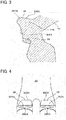
Fig. 3 is a sectional view illustrating a cutaway of a convex portion along a sectional surface of line A-A ofFig. 2 . -
Fig. 4 is a view for describing the convex portion formed in the intake port when viewed from an inside of the cylinder chamber. -
Fig. 5 is a view illustrating a cylinder chamber, an intake port, and an exhaust port in a second embodiment when viewed from the upstream side of the intake port. - Hereinafter, the embodiments of the invention will be described with reference to the drawings.
- As illustrated in
Fig. 1 , an internal combustion engine (engine) 10 includes acylinder block 14 in which a plurality ofcylinder chambers 12 are formed, acylinder head 16 which is provided on the upper side of thecylinder block 14, and apiston 18 which is arranged in thecylinder chamber 12. - A
combustion chamber 20 is configured by an innercircumferential surface 1202 of thecylinder chamber 12, alower surface 1602 of thecylinder head 16, and atop surface 1802 of thepiston 18. - The
cylinder head 16 is provided with twointake ports 22,intake valves 24 which open and close therespective intake ports 22, twoexhaust ports 26,exhaust valves 28 which open and close therespective exhaust ports 26, and anignition plug 30. - The
ignition plug 30 is provided in thelower surface 1602 of thecylinder head 16 to be positioned at the almost center of thecombustion chamber 20. - Each of the
intake ports 22 includes anupstream portion 2202 which communicates with anintake manifold 31 to extend on the upper side of thecylinder chamber 12 in the radial direction of thecylinder chamber 12, and adownstream portion 2204 which is connected to theupstream portion 2202 and is curved to thecylinder chamber 12 side. - An
intake valve seat 32 is mounted in the downstream end of thedownstream portion 2204, and theintake port 22 is closed and opened by contacting and separating theintake valve 24 on and from theintake valve seat 32. - As illustrated in
Figs. 1 and2 , aportion 34, which is adjacent to the upstream side with respect to theintake valve seat 32, of thedownstream portion 2204 includes acentral wall part 34A which extends on the central portion side of thecylinder chamber 12 in a semi-arc shape and an outercircumferential wall part 34B which extends on the outer circumferential side of thecylinder chamber 12 in a semi-arc shape. - As illustrated in
Figs. 1 and3 , in the outercircumferential wall part 34B of each of theintake ports 22, aconvex portion 36 for generating a tumble flow T1 is respectively formed to protrude to the inside of theintake port 22. Areference numeral 3610 denotes the apex of theconvex portion 36. - As illustrated in
Figs. 1 to 4 , the eachconvex portion 36 includes anupstream guide surface 3602 and adownstream guide surface 3604 respectively. - The
upstream guide surface 3602 extends from theapex 3610 to an intake upstream side. - The
downstream guide surface 3604 extends from theapex 3610 to the intake downstream side to form a curved surface recessed inside theconvex portion 36 at a middle portion. - As illustrated in
Figs. 2 and4 , theapex 3610 linearly extends in a direction orthogonal to the flow direction of the intake air of theintake port 22 when viewed from the upstream side of the intake air inside theintake port 22. - The
upstream guide surface 3602 is formed slantingly such that the intake air which flows in thecylinder chamber 12 from theintake port 22 forms the tumble flow T1. - In other words, the
upstream guide surface 3602 is formed such that the intake air which flows through theintake port 22 is directed to the center of thecylinder chamber 12. - The
upstream guide surface 3602 is continuously connected with the wall surface of theintake port 22 to form an obtuse angle. - At the time of the intake stroke of the
intake valve 24, thedownstream guide surface 3604 guides the fuel-air mixture, which is guided by the tumble flow T1 from thecylinder chamber 12 to the outercircumferential wall part 34B about to return to theintake port 22, to thecentral wall part 34A, thereby preventing that the fuel-air mixture returns to the upstream side of theintake port 22. - When the description is given in more detail, the tip of the
downstream guide surface 3604 is directed toward the portion of thecentral wall part 34A which extends on the central portion side of thecylinder chamber 12 in a semi-arc shape. - In addition, the
apex 3610 is formed in a streamline in which theupstream guide surface 3602 and thedownstream guide surface 3604 are connected in a curved line. - Incidentally, at the time of casting the
cylinder head 16, theconvex portion 36 is formed by a mold, theapex 3610 and theupstream guide surface 3602 are formed in a core (mold), and thedownstream guide surface 3604 is formed by cutting processing. - Therefore, the convex
portion 36 can be produced simply, which is advantageous for improving the productivity. - Incidentally, it is also considered that the
apex 3610 of theconvex portion 36 is formed by the cutting processing. However, in that case, the position of theapex 3610 may be deviated according to the accuracy of the cutting processing. In addition, since the cutting processing is performed by a drill or the like, it is considered that theapex 3610 cannot be formed linearly, and the timing when the intake air is directed to the center of thecylinder chamber 12 is deviated in the radial direction, so as to affect the formation of the tumble flow T1. Further, since the end surface of the cutting processing is edged, it is also considered that a turbulence is generated by the edge, and the formation of the tumble flow T1 is also affected by the turbulence. - Thus, when the
convex portion 36 is formed in the mold of the casting, theapex 3610 can be formed in a streamline which is connected in the curved line. Further, the edge made by the cutting processing is on the downstream side of theapex 3610, and thus the effect of the edge to the formation of the tumble flow can be reduced. - The following operational effects are obtained according to this embodiment.
- The
downstream guide surface 3604 guides the fuel-air mixture, which is guided by the tumble flow T1 from thecylinder chamber 12 to the outercircumferential wall part 34B about to return to theintake port 22, from the outercircumferential wall part 34B to thecentral wall part 34A. Thus, the intake air, which is about to return from thecylinder chamber 12 to the upstream side of theintake port 22 by the tumble flow T1, is blocked by the flow T2 of the guided fuel-air mixture. - Therefore, it is advantageous for preventing that the fuel-air mixture in the
cylinder chamber 12 flows back to theintake port 22, and it is advantageous for improving the charging efficiency. - In addition, the
apex 3610 extends linearly in a direction orthogonal to the flow direction of the intake air of theintake port 22. Thus, the intake air is guided into thecylinder chamber 12 by theupstream guide surface 3602 of theconvex portion 36 to form the tumble flow T1, and the intake air which is guided by theupstream guide surface 3602 of theconvex portion 36 is not deflected in the extending direction of theapex 3610. Therefore, it is possible to strengthen the tumble flow T1, it is advantageous for guiding the intake air into thecylinder chamber 12 efficiently, and it is advantageous for improving the charging efficiency. - In addition, the
upstream guide surface 3602 and the wall surface of theintake port 22 are continuously connected to form an obtuse angle. Thus, the resistance due to theupstream guide surface 3602 is controlled while the intake air is deflected by theupstream guide surface 3602 to strengthen the tumble flow T1. It is advantageous for guiding the intake air into thecylinder chamber 12 efficiently, and it is advantageous for improving the charging efficiency. - Incidentally, the
downstream guide surface 3604 may be formed such that the fuel-air mixture, which is guided by the tumble flow T1 from thecylinder chamber 12 to the outercircumferential wall part 34B about to return to theintake port 22, is directed from the outercircumferential wall part 34B to aback surface 2404 of theintake valve 24 which faces the outercircumferential wall part 34B, so that a swirl flow is formed between thedownstream guide surface 3604 and theback surface 2404 of theintake valve 24. In that case, the intake air, which is about to return from thecylinder chamber 12 to the upstream side of theintake port 22 by the tumble flow T1, is blocked by the swirl flow. Thus, it is advantageous for preventing that the fuel-air mixture in thecylinder chamber 12 flows back to theintake port 22, and it is advantageous for improving the charging efficiency. - Next, a second embodiment will be described with reference to
Fig. 5 . - Incidentally, in the following embodiment, the same portions and members as those of the first embodiment are denoted by the same reference numerals as those of the first embodiment, and the explanation thereof is not repeated.
- The second embodiment is different from the first embodiment in that the
convex portion 36 includes twoapexes upstream guide surface 3602 and thedownstream guide surface 3604 are formed in each of theconvex portions 36. - When the description is given in more detail, when viewed from the upstream side of the
intake port 22, theconvex portion 36 includes afirst portion 36A in which theapex 3610A extends linearly and asecond portion 36B in which the apex 3610B with a smaller protruding amount than the apex 3610A extends linearly. - Each of the
apexes intake port 22. - In this embodiment, two
intake ports 22 are provided side by side with respect to onecylinder chamber 12. Thus, thefirst portions 36A are formed at places, which are apart from each other, of theconvex portions 36. In other words, theapexes convex portions convex portions intake ports 22 when viewed from the upper side of thecylinder chamber 12. - In the second embodiment, the same effect as that of the first embodiment is obtained, and the
second portions 36B which have smaller protruding amount than thefirst portion 36A are formed at places, which are near the center of thecylinder chamber 12, of theconvex portions 36 in twointake ports 22. Thus, at the time of the intake stroke, it is more advantageous for strengthening the tumble flow T1 whch is directed to the center (deep portion) of thecylinder chamber 12.
Claims (4)
- An intake structure of an internal combustion engine, wherein
on an intake upstream side from a valve seat of an intake port, a convex portion is provided which protrudes to an inside of the intake port in a place near an outer circumferential portion of a cylinder chamber when viewed from an upper side of the cylinder chamber, and
the convex portion includes:an upstream guide surface extending from an apex of the convex portion to the intake upstream side, anda downstream guide surface extending from the apex to an intake downstream side and including a curved surface recessed inside the convex portion at a middle portion thereof. - The intake structure of the internal combustion engine according to claim 1, wherein the apex extends in a direction orthogonal to a flow direction of an intake air which flows through the intake port.
- The intake structure of the internal combustion engine according to claim 1 or 2, wherein two intake ports are provided side by side with respect to one cylinder chamber,
the convex portion is provided each of the two intake ports, and
an inside of the apex of each of the convex portions is formed to be lower than an outside of the apex. - The intake structure of the internal combustion engine according to claim 3, wherein a shape of the convex portion is formed to be linearly symmetrical to a virtual line drawn between the two intake ports when viewed from the upper side of the cylinder chamber.
Applications Claiming Priority (1)
| Application Number | Priority Date | Filing Date | Title |
|---|---|---|---|
| JP2017242410A JP7003626B2 (en) | 2017-12-19 | 2017-12-19 | Intake structure of internal combustion engine |
Publications (2)
| Publication Number | Publication Date |
|---|---|
| EP3502449A1 true EP3502449A1 (en) | 2019-06-26 |
| EP3502449B1 EP3502449B1 (en) | 2020-10-28 |
Family
ID=64664600
Family Applications (1)
| Application Number | Title | Priority Date | Filing Date |
|---|---|---|---|
| EP18211449.6A Active EP3502449B1 (en) | 2017-12-19 | 2018-12-10 | Intake structure of internal combustion engine |
Country Status (4)
| Country | Link |
|---|---|
| US (1) | US10648398B2 (en) |
| EP (1) | EP3502449B1 (en) |
| JP (1) | JP7003626B2 (en) |
| CN (1) | CN109989824B (en) |
Families Citing this family (2)
| Publication number | Priority date | Publication date | Assignee | Title |
|---|---|---|---|---|
| CN114776459B (en) * | 2021-06-25 | 2024-08-09 | 长城汽车股份有限公司 | Engine air intake system |
| CN119195934B (en) * | 2024-10-14 | 2025-03-18 | 常州市海润机电有限公司 | An intake high swirl cylinder head and a diesel engine |
Citations (7)
| Publication number | Priority date | Publication date | Assignee | Title |
|---|---|---|---|---|
| FR2037270A1 (en) * | 1969-03-27 | 1970-12-31 | List Hans | |
| JPH0725235U (en) | 1993-09-29 | 1995-05-12 | 富士重工業株式会社 | Engine intake system |
| JP2004316609A (en) | 2003-04-18 | 2004-11-11 | Toyota Motor Corp | Internal combustion engine with intake port for tumble flow formation |
| FR2910541A1 (en) * | 2006-12-21 | 2008-06-27 | Renault Sas | Gas intake system for e.g. direct injection petrol engine, has wheel ramp arranged in gas intake conduit at level of concave side and placed near valve seat, where wheel ramp is obtained by molding in sand core mold |
| FR2923268A1 (en) * | 2007-11-05 | 2009-05-08 | Renault Sas | Cylinder head for e.g. petrol engine of vehicle, has cylindrical wall provided with rectilinear axle part whose ramp is inclined towards center of intake duct and is located near interior side of elbow |
| EP2787208A1 (en) * | 2013-04-05 | 2014-10-08 | Fiat Group Automobiles S.p.A. | Cylinder head for an internal-combustion engine with intake ducts having an air-deflecting projection |
| DE102016003555A1 (en) * | 2015-03-24 | 2016-09-29 | Mazda Motor Corporation | INTAKE-IN DEVICE FOR A MOTOR, ENGINE AND MANUFACTURING PROCESS |
Family Cites Families (6)
| Publication number | Priority date | Publication date | Assignee | Title |
|---|---|---|---|---|
| JP2000179417A (en) * | 1998-12-16 | 2000-06-27 | Suzuki Motor Corp | Engine intake system |
| US6604424B1 (en) * | 1999-06-16 | 2003-08-12 | Denso Corporation | Pressure detecting apparatus and installation structure of same |
| JP4285235B2 (en) * | 2003-12-25 | 2009-06-24 | 日産自動車株式会社 | Intake port structure of internal combustion engine |
| JP2005337190A (en) * | 2004-05-31 | 2005-12-08 | Denso Corp | Inlet throttle device for internal combustion engine |
| GB201001562D0 (en) * | 2010-01-29 | 2010-03-17 | Ricardo Uk Ltd | Direct injection diesel |
| US8430074B2 (en) * | 2010-12-13 | 2013-04-30 | Ford Global Technologies, Llc | Rotatable valve in a cylinder intake duct |
-
2017
- 2017-12-19 JP JP2017242410A patent/JP7003626B2/en active Active
-
2018
- 2018-12-06 CN CN201811487979.4A patent/CN109989824B/en active Active
- 2018-12-10 EP EP18211449.6A patent/EP3502449B1/en active Active
- 2018-12-18 US US16/224,420 patent/US10648398B2/en active Active
Patent Citations (7)
| Publication number | Priority date | Publication date | Assignee | Title |
|---|---|---|---|---|
| FR2037270A1 (en) * | 1969-03-27 | 1970-12-31 | List Hans | |
| JPH0725235U (en) | 1993-09-29 | 1995-05-12 | 富士重工業株式会社 | Engine intake system |
| JP2004316609A (en) | 2003-04-18 | 2004-11-11 | Toyota Motor Corp | Internal combustion engine with intake port for tumble flow formation |
| FR2910541A1 (en) * | 2006-12-21 | 2008-06-27 | Renault Sas | Gas intake system for e.g. direct injection petrol engine, has wheel ramp arranged in gas intake conduit at level of concave side and placed near valve seat, where wheel ramp is obtained by molding in sand core mold |
| FR2923268A1 (en) * | 2007-11-05 | 2009-05-08 | Renault Sas | Cylinder head for e.g. petrol engine of vehicle, has cylindrical wall provided with rectilinear axle part whose ramp is inclined towards center of intake duct and is located near interior side of elbow |
| EP2787208A1 (en) * | 2013-04-05 | 2014-10-08 | Fiat Group Automobiles S.p.A. | Cylinder head for an internal-combustion engine with intake ducts having an air-deflecting projection |
| DE102016003555A1 (en) * | 2015-03-24 | 2016-09-29 | Mazda Motor Corporation | INTAKE-IN DEVICE FOR A MOTOR, ENGINE AND MANUFACTURING PROCESS |
Also Published As
| Publication number | Publication date |
|---|---|
| US10648398B2 (en) | 2020-05-12 |
| CN109989824A (en) | 2019-07-09 |
| JP7003626B2 (en) | 2022-01-20 |
| EP3502449B1 (en) | 2020-10-28 |
| CN109989824B (en) | 2022-01-28 |
| JP2019108844A (en) | 2019-07-04 |
| US20190186343A1 (en) | 2019-06-20 |
Similar Documents
| Publication | Publication Date | Title |
|---|---|---|
| KR100608182B1 (en) | Intake apparatus for internal combustion engine | |
| US6904891B2 (en) | Intake system of internal combustion engine | |
| KR100608181B1 (en) | Intake apparatus for internal combustion engine | |
| EP3502449B1 (en) | Intake structure of internal combustion engine | |
| US20190360428A1 (en) | Diesel engine | |
| US11326548B2 (en) | Engine | |
| EP2423483B1 (en) | Combustion chamber construction for engine | |
| US20200011267A1 (en) | Diesel engine | |
| EP3779141A1 (en) | Combustion chamber structure of internal combustion engine | |
| JP5702129B2 (en) | Engine combustion chamber structure and cylinder head structure | |
| US5605123A (en) | Intake port structure in internal combustion engine | |
| US10400720B2 (en) | Partition plate | |
| JP2008274788A (en) | Engine combustion chamber structure | |
| KR20220023534A (en) | Intake valve seat and cylinder structure of engine | |
| JPH077544Y2 (en) | Engine combustion chamber structure | |
| JP2005113694A (en) | Internal combustion engine | |
| JP5930676B2 (en) | Combustion chamber structure of internal combustion engine | |
| JP2026052345A (en) | Internal combustion engine | |
| JP2019132219A (en) | Internal combustion engine | |
| JP2020143607A (en) | engine | |
| JP2019044704A (en) | Combustion chamber of internal combustion engine | |
| JP2018204511A (en) | Intake passage structure for engine | |
| JP2017172410A (en) | Combustion chamber structure of direct injection engine | |
| JPH02181019A (en) | Combustion chamber with dome-shaped auxiliary combustion chamber for spark-ignited overhead valve engine |
Legal Events
| Date | Code | Title | Description |
|---|---|---|---|
| PUAI | Public reference made under article 153(3) epc to a published international application that has entered the european phase |
Free format text: ORIGINAL CODE: 0009012 |
|
| STAA | Information on the status of an ep patent application or granted ep patent |
Free format text: STATUS: REQUEST FOR EXAMINATION WAS MADE |
|
| 17P | Request for examination filed |
Effective date: 20181210 |
|
| AK | Designated contracting states |
Kind code of ref document: A1 Designated state(s): AL AT BE BG CH CY CZ DE DK EE ES FI FR GB GR HR HU IE IS IT LI LT LU LV MC MK MT NL NO PL PT RO RS SE SI SK SM TR |
|
| AX | Request for extension of the european patent |
Extension state: BA ME |
|
| RAP1 | Party data changed (applicant data changed or rights of an application transferred) |
Owner name: MITSUBISHI JIDOSHA KOGYO KABUSHIKI KAISHA |
|
| GRAP | Despatch of communication of intention to grant a patent |
Free format text: ORIGINAL CODE: EPIDOSNIGR1 |
|
| STAA | Information on the status of an ep patent application or granted ep patent |
Free format text: STATUS: GRANT OF PATENT IS INTENDED |
|
| RIC1 | Information provided on ipc code assigned before grant |
Ipc: F02B 23/10 20060101ALN20200504BHEP Ipc: F02F 1/42 20060101AFI20200504BHEP Ipc: F02B 31/04 20060101ALI20200504BHEP Ipc: F02B 75/12 20060101ALN20200504BHEP |
|
| INTG | Intention to grant announced |
Effective date: 20200609 |
|
| GRAS | Grant fee paid |
Free format text: ORIGINAL CODE: EPIDOSNIGR3 |
|
| GRAA | (expected) grant |
Free format text: ORIGINAL CODE: 0009210 |
|
| STAA | Information on the status of an ep patent application or granted ep patent |
Free format text: STATUS: THE PATENT HAS BEEN GRANTED |
|
| AK | Designated contracting states |
Kind code of ref document: B1 Designated state(s): AL AT BE BG CH CY CZ DE DK EE ES FI FR GB GR HR HU IE IS IT LI LT LU LV MC MK MT NL NO PL PT RO RS SE SI SK SM TR |
|
| REG | Reference to a national code |
Ref country code: GB Ref legal event code: FG4D |
|
| REG | Reference to a national code |
Ref country code: CH Ref legal event code: EP |
|
| REG | Reference to a national code |
Ref country code: AT Ref legal event code: REF Ref document number: 1328473 Country of ref document: AT Kind code of ref document: T Effective date: 20201115 |
|
| REG | Reference to a national code |
Ref country code: DE Ref legal event code: R096 Ref document number: 602018009129 Country of ref document: DE |
|
| REG | Reference to a national code |
Ref country code: IE Ref legal event code: FG4D |
|
| REG | Reference to a national code |
Ref country code: AT Ref legal event code: MK05 Ref document number: 1328473 Country of ref document: AT Kind code of ref document: T Effective date: 20201028 |
|
| REG | Reference to a national code |
Ref country code: NL Ref legal event code: MP Effective date: 20201028 |
|
| PG25 | Lapsed in a contracting state [announced via postgrant information from national office to epo] |
Ref country code: GR Free format text: LAPSE BECAUSE OF FAILURE TO SUBMIT A TRANSLATION OF THE DESCRIPTION OR TO PAY THE FEE WITHIN THE PRESCRIBED TIME-LIMIT Effective date: 20210129 Ref country code: NO Free format text: LAPSE BECAUSE OF FAILURE TO SUBMIT A TRANSLATION OF THE DESCRIPTION OR TO PAY THE FEE WITHIN THE PRESCRIBED TIME-LIMIT Effective date: 20210128 Ref country code: FI Free format text: LAPSE BECAUSE OF FAILURE TO SUBMIT A TRANSLATION OF THE DESCRIPTION OR TO PAY THE FEE WITHIN THE PRESCRIBED TIME-LIMIT Effective date: 20201028 Ref country code: RS Free format text: LAPSE BECAUSE OF FAILURE TO SUBMIT A TRANSLATION OF THE DESCRIPTION OR TO PAY THE FEE WITHIN THE PRESCRIBED TIME-LIMIT Effective date: 20201028 Ref country code: PT Free format text: LAPSE BECAUSE OF FAILURE TO SUBMIT A TRANSLATION OF THE DESCRIPTION OR TO PAY THE FEE WITHIN THE PRESCRIBED TIME-LIMIT Effective date: 20210301 |
|
| REG | Reference to a national code |
Ref country code: LT Ref legal event code: MG4D |
|
| PG25 | Lapsed in a contracting state [announced via postgrant information from national office to epo] |
Ref country code: BG Free format text: LAPSE BECAUSE OF FAILURE TO SUBMIT A TRANSLATION OF THE DESCRIPTION OR TO PAY THE FEE WITHIN THE PRESCRIBED TIME-LIMIT Effective date: 20210128 Ref country code: PL Free format text: LAPSE BECAUSE OF FAILURE TO SUBMIT A TRANSLATION OF THE DESCRIPTION OR TO PAY THE FEE WITHIN THE PRESCRIBED TIME-LIMIT Effective date: 20201028 Ref country code: IS Free format text: LAPSE BECAUSE OF FAILURE TO SUBMIT A TRANSLATION OF THE DESCRIPTION OR TO PAY THE FEE WITHIN THE PRESCRIBED TIME-LIMIT Effective date: 20210228 Ref country code: LV Free format text: LAPSE BECAUSE OF FAILURE TO SUBMIT A TRANSLATION OF THE DESCRIPTION OR TO PAY THE FEE WITHIN THE PRESCRIBED TIME-LIMIT Effective date: 20201028 Ref country code: SE Free format text: LAPSE BECAUSE OF FAILURE TO SUBMIT A TRANSLATION OF THE DESCRIPTION OR TO PAY THE FEE WITHIN THE PRESCRIBED TIME-LIMIT Effective date: 20201028 Ref country code: ES Free format text: LAPSE BECAUSE OF FAILURE TO SUBMIT A TRANSLATION OF THE DESCRIPTION OR TO PAY THE FEE WITHIN THE PRESCRIBED TIME-LIMIT Effective date: 20201028 Ref country code: AT Free format text: LAPSE BECAUSE OF FAILURE TO SUBMIT A TRANSLATION OF THE DESCRIPTION OR TO PAY THE FEE WITHIN THE PRESCRIBED TIME-LIMIT Effective date: 20201028 |
|
| PG25 | Lapsed in a contracting state [announced via postgrant information from national office to epo] |
Ref country code: HR Free format text: LAPSE BECAUSE OF FAILURE TO SUBMIT A TRANSLATION OF THE DESCRIPTION OR TO PAY THE FEE WITHIN THE PRESCRIBED TIME-LIMIT Effective date: 20201028 Ref country code: NL Free format text: LAPSE BECAUSE OF FAILURE TO SUBMIT A TRANSLATION OF THE DESCRIPTION OR TO PAY THE FEE WITHIN THE PRESCRIBED TIME-LIMIT Effective date: 20201028 |
|
| REG | Reference to a national code |
Ref country code: DE Ref legal event code: R097 Ref document number: 602018009129 Country of ref document: DE |
|
| PG25 | Lapsed in a contracting state [announced via postgrant information from national office to epo] |
Ref country code: LT Free format text: LAPSE BECAUSE OF FAILURE TO SUBMIT A TRANSLATION OF THE DESCRIPTION OR TO PAY THE FEE WITHIN THE PRESCRIBED TIME-LIMIT Effective date: 20201028 Ref country code: RO Free format text: LAPSE BECAUSE OF FAILURE TO SUBMIT A TRANSLATION OF THE DESCRIPTION OR TO PAY THE FEE WITHIN THE PRESCRIBED TIME-LIMIT Effective date: 20201028 Ref country code: SM Free format text: LAPSE BECAUSE OF FAILURE TO SUBMIT A TRANSLATION OF THE DESCRIPTION OR TO PAY THE FEE WITHIN THE PRESCRIBED TIME-LIMIT Effective date: 20201028 Ref country code: SK Free format text: LAPSE BECAUSE OF FAILURE TO SUBMIT A TRANSLATION OF THE DESCRIPTION OR TO PAY THE FEE WITHIN THE PRESCRIBED TIME-LIMIT Effective date: 20201028 Ref country code: CZ Free format text: LAPSE BECAUSE OF FAILURE TO SUBMIT A TRANSLATION OF THE DESCRIPTION OR TO PAY THE FEE WITHIN THE PRESCRIBED TIME-LIMIT Effective date: 20201028 Ref country code: EE Free format text: LAPSE BECAUSE OF FAILURE TO SUBMIT A TRANSLATION OF THE DESCRIPTION OR TO PAY THE FEE WITHIN THE PRESCRIBED TIME-LIMIT Effective date: 20201028 |
|
| PG25 | Lapsed in a contracting state [announced via postgrant information from national office to epo] |
Ref country code: DK Free format text: LAPSE BECAUSE OF FAILURE TO SUBMIT A TRANSLATION OF THE DESCRIPTION OR TO PAY THE FEE WITHIN THE PRESCRIBED TIME-LIMIT Effective date: 20201028 Ref country code: MC Free format text: LAPSE BECAUSE OF FAILURE TO SUBMIT A TRANSLATION OF THE DESCRIPTION OR TO PAY THE FEE WITHIN THE PRESCRIBED TIME-LIMIT Effective date: 20201028 |
|
| PLBE | No opposition filed within time limit |
Free format text: ORIGINAL CODE: 0009261 |
|
| REG | Reference to a national code |
Ref country code: BE Ref legal event code: MM Effective date: 20201231 |
|
| STAA | Information on the status of an ep patent application or granted ep patent |
Free format text: STATUS: NO OPPOSITION FILED WITHIN TIME LIMIT |
|
| 26N | No opposition filed |
Effective date: 20210729 |
|
| PG25 | Lapsed in a contracting state [announced via postgrant information from national office to epo] |
Ref country code: IT Free format text: LAPSE BECAUSE OF FAILURE TO SUBMIT A TRANSLATION OF THE DESCRIPTION OR TO PAY THE FEE WITHIN THE PRESCRIBED TIME-LIMIT Effective date: 20201028 Ref country code: LU Free format text: LAPSE BECAUSE OF NON-PAYMENT OF DUE FEES Effective date: 20201210 Ref country code: IE Free format text: LAPSE BECAUSE OF NON-PAYMENT OF DUE FEES Effective date: 20201210 Ref country code: AL Free format text: LAPSE BECAUSE OF FAILURE TO SUBMIT A TRANSLATION OF THE DESCRIPTION OR TO PAY THE FEE WITHIN THE PRESCRIBED TIME-LIMIT Effective date: 20201028 |
|
| PG25 | Lapsed in a contracting state [announced via postgrant information from national office to epo] |
Ref country code: SI Free format text: LAPSE BECAUSE OF FAILURE TO SUBMIT A TRANSLATION OF THE DESCRIPTION OR TO PAY THE FEE WITHIN THE PRESCRIBED TIME-LIMIT Effective date: 20201028 |
|
| PG25 | Lapsed in a contracting state [announced via postgrant information from national office to epo] |
Ref country code: IS Free format text: LAPSE BECAUSE OF FAILURE TO SUBMIT A TRANSLATION OF THE DESCRIPTION OR TO PAY THE FEE WITHIN THE PRESCRIBED TIME-LIMIT Effective date: 20210228 Ref country code: TR Free format text: LAPSE BECAUSE OF FAILURE TO SUBMIT A TRANSLATION OF THE DESCRIPTION OR TO PAY THE FEE WITHIN THE PRESCRIBED TIME-LIMIT Effective date: 20201028 Ref country code: MT Free format text: LAPSE BECAUSE OF FAILURE TO SUBMIT A TRANSLATION OF THE DESCRIPTION OR TO PAY THE FEE WITHIN THE PRESCRIBED TIME-LIMIT Effective date: 20201028 Ref country code: CY Free format text: LAPSE BECAUSE OF FAILURE TO SUBMIT A TRANSLATION OF THE DESCRIPTION OR TO PAY THE FEE WITHIN THE PRESCRIBED TIME-LIMIT Effective date: 20201028 |
|
| PG25 | Lapsed in a contracting state [announced via postgrant information from national office to epo] |
Ref country code: MK Free format text: LAPSE BECAUSE OF FAILURE TO SUBMIT A TRANSLATION OF THE DESCRIPTION OR TO PAY THE FEE WITHIN THE PRESCRIBED TIME-LIMIT Effective date: 20201028 |
|
| PG25 | Lapsed in a contracting state [announced via postgrant information from national office to epo] |
Ref country code: BE Free format text: LAPSE BECAUSE OF NON-PAYMENT OF DUE FEES Effective date: 20201231 |
|
| REG | Reference to a national code |
Ref country code: CH Ref legal event code: PL |
|
| PG25 | Lapsed in a contracting state [announced via postgrant information from national office to epo] |
Ref country code: LI Free format text: LAPSE BECAUSE OF NON-PAYMENT OF DUE FEES Effective date: 20211231 Ref country code: CH Free format text: LAPSE BECAUSE OF NON-PAYMENT OF DUE FEES Effective date: 20211231 |
|
| GBPC | Gb: european patent ceased through non-payment of renewal fee |
Effective date: 20221210 |
|
| PG25 | Lapsed in a contracting state [announced via postgrant information from national office to epo] |
Ref country code: GB Free format text: LAPSE BECAUSE OF NON-PAYMENT OF DUE FEES Effective date: 20221210 |
|
| PGFP | Annual fee paid to national office [announced via postgrant information from national office to epo] |
Ref country code: DE Payment date: 20251028 Year of fee payment: 8 |
|
| PGFP | Annual fee paid to national office [announced via postgrant information from national office to epo] |
Ref country code: FR Payment date: 20251110 Year of fee payment: 8 |