EP3502444A1 - Methods and apparatus for controlling electrical power supplied to a component of a vehicle - Google Patents
Methods and apparatus for controlling electrical power supplied to a component of a vehicle Download PDFInfo
- Publication number
- EP3502444A1 EP3502444A1 EP18207297.5A EP18207297A EP3502444A1 EP 3502444 A1 EP3502444 A1 EP 3502444A1 EP 18207297 A EP18207297 A EP 18207297A EP 3502444 A1 EP3502444 A1 EP 3502444A1
- Authority
- EP
- European Patent Office
- Prior art keywords
- electrical power
- component
- gas turbine
- vehicle
- turbine engine
- Prior art date
- Legal status (The legal status is an assumption and is not a legal conclusion. Google has not performed a legal analysis and makes no representation as to the accuracy of the status listed.)
- Granted
Links
Images


Classifications
-
- F—MECHANICAL ENGINEERING; LIGHTING; HEATING; WEAPONS; BLASTING
- F01—MACHINES OR ENGINES IN GENERAL; ENGINE PLANTS IN GENERAL; STEAM ENGINES
- F01D—NON-POSITIVE DISPLACEMENT MACHINES OR ENGINES, e.g. STEAM TURBINES
- F01D15/00—Adaptations of machines or engines for special use; Combinations of engines with devices driven thereby
- F01D15/10—Adaptations for driving, or combinations with, electric generators
-
- B—PERFORMING OPERATIONS; TRANSPORTING
- B64—AIRCRAFT; AVIATION; COSMONAUTICS
- B64D—EQUIPMENT FOR FITTING IN OR TO AIRCRAFT; FLIGHT SUITS; PARACHUTES; ARRANGEMENT OR MOUNTING OF POWER PLANTS OR PROPULSION TRANSMISSIONS IN AIRCRAFT
- B64D27/00—Arrangement or mounting of power plants in aircraft; Aircraft characterised by the type or position of power plants
- B64D27/02—Aircraft characterised by the type or position of power plants
- B64D27/10—Aircraft characterised by the type or position of power plants of gas-turbine type
-
- B—PERFORMING OPERATIONS; TRANSPORTING
- B64—AIRCRAFT; AVIATION; COSMONAUTICS
- B64D—EQUIPMENT FOR FITTING IN OR TO AIRCRAFT; FLIGHT SUITS; PARACHUTES; ARRANGEMENT OR MOUNTING OF POWER PLANTS OR PROPULSION TRANSMISSIONS IN AIRCRAFT
- B64D31/00—Power plant control systems; Arrangement of power plant control systems in aircraft
-
- B—PERFORMING OPERATIONS; TRANSPORTING
- B64—AIRCRAFT; AVIATION; COSMONAUTICS
- B64F—GROUND OR AIRCRAFT-CARRIER-DECK INSTALLATIONS SPECIALLY ADAPTED FOR USE IN CONNECTION WITH AIRCRAFT; DESIGNING, MANUFACTURING, ASSEMBLING, CLEANING, MAINTAINING OR REPAIRING AIRCRAFT, NOT OTHERWISE PROVIDED FOR; HANDLING, TRANSPORTING, TESTING OR INSPECTING AIRCRAFT COMPONENTS, NOT OTHERWISE PROVIDED FOR
- B64F5/00—Designing, manufacturing, assembling, cleaning, maintaining or repairing aircraft, not otherwise provided for; Handling, transporting, testing or inspecting aircraft components, not otherwise provided for
- B64F5/60—Testing or inspecting aircraft components or systems
-
- F—MECHANICAL ENGINEERING; LIGHTING; HEATING; WEAPONS; BLASTING
- F01—MACHINES OR ENGINES IN GENERAL; ENGINE PLANTS IN GENERAL; STEAM ENGINES
- F01D—NON-POSITIVE DISPLACEMENT MACHINES OR ENGINES, e.g. STEAM TURBINES
- F01D25/00—Component parts, details, or accessories, not provided for in, or of interest apart from, other groups
- F01D25/02—De-icing means for engines having icing phenomena
-
- F—MECHANICAL ENGINEERING; LIGHTING; HEATING; WEAPONS; BLASTING
- F02—COMBUSTION ENGINES; HOT-GAS OR COMBUSTION-PRODUCT ENGINE PLANTS
- F02C—GAS-TURBINE PLANTS; AIR INTAKES FOR JET-PROPULSION PLANTS; CONTROLLING FUEL SUPPLY IN AIR-BREATHING JET-PROPULSION PLANTS
- F02C6/00—Plural gas-turbine plants; Combinations of gas-turbine plants with other apparatus; Adaptations of gas-turbine plants for special use
-
- F—MECHANICAL ENGINEERING; LIGHTING; HEATING; WEAPONS; BLASTING
- F02—COMBUSTION ENGINES; HOT-GAS OR COMBUSTION-PRODUCT ENGINE PLANTS
- F02C—GAS-TURBINE PLANTS; AIR INTAKES FOR JET-PROPULSION PLANTS; CONTROLLING FUEL SUPPLY IN AIR-BREATHING JET-PROPULSION PLANTS
- F02C7/00—Features, components parts, details or accessories, not provided for in, or of interest apart form groups F02C1/00 - F02C6/00; Air intakes for jet-propulsion plants
- F02C7/04—Air intakes for gas-turbine plants or jet-propulsion plants
- F02C7/047—Heating to prevent icing
-
- F—MECHANICAL ENGINEERING; LIGHTING; HEATING; WEAPONS; BLASTING
- F02—COMBUSTION ENGINES; HOT-GAS OR COMBUSTION-PRODUCT ENGINE PLANTS
- F02C—GAS-TURBINE PLANTS; AIR INTAKES FOR JET-PROPULSION PLANTS; CONTROLLING FUEL SUPPLY IN AIR-BREATHING JET-PROPULSION PLANTS
- F02C7/00—Features, components parts, details or accessories, not provided for in, or of interest apart form groups F02C1/00 - F02C6/00; Air intakes for jet-propulsion plants
- F02C7/04—Air intakes for gas-turbine plants or jet-propulsion plants
- F02C7/057—Control or regulation
-
- F—MECHANICAL ENGINEERING; LIGHTING; HEATING; WEAPONS; BLASTING
- F02—COMBUSTION ENGINES; HOT-GAS OR COMBUSTION-PRODUCT ENGINE PLANTS
- F02C—GAS-TURBINE PLANTS; AIR INTAKES FOR JET-PROPULSION PLANTS; CONTROLLING FUEL SUPPLY IN AIR-BREATHING JET-PROPULSION PLANTS
- F02C7/00—Features, components parts, details or accessories, not provided for in, or of interest apart form groups F02C1/00 - F02C6/00; Air intakes for jet-propulsion plants
- F02C7/32—Arrangement, mounting, or driving, of auxiliaries
-
- F—MECHANICAL ENGINEERING; LIGHTING; HEATING; WEAPONS; BLASTING
- F02—COMBUSTION ENGINES; HOT-GAS OR COMBUSTION-PRODUCT ENGINE PLANTS
- F02C—GAS-TURBINE PLANTS; AIR INTAKES FOR JET-PROPULSION PLANTS; CONTROLLING FUEL SUPPLY IN AIR-BREATHING JET-PROPULSION PLANTS
- F02C9/00—Controlling gas-turbine plants; Controlling fuel supply in air- breathing jet-propulsion plants
-
- G—PHYSICS
- G06—COMPUTING OR CALCULATING; COUNTING
- G06F—ELECTRIC DIGITAL DATA PROCESSING
- G06F30/00—Computer-aided design [CAD]
- G06F30/20—Design optimisation, verification or simulation
-
- B—PERFORMING OPERATIONS; TRANSPORTING
- B64—AIRCRAFT; AVIATION; COSMONAUTICS
- B64D—EQUIPMENT FOR FITTING IN OR TO AIRCRAFT; FLIGHT SUITS; PARACHUTES; ARRANGEMENT OR MOUNTING OF POWER PLANTS OR PROPULSION TRANSMISSIONS IN AIRCRAFT
- B64D15/00—De-icing or preventing icing on exterior surfaces of aircraft
- B64D15/12—De-icing or preventing icing on exterior surfaces of aircraft by electric heating
-
- B—PERFORMING OPERATIONS; TRANSPORTING
- B64—AIRCRAFT; AVIATION; COSMONAUTICS
- B64D—EQUIPMENT FOR FITTING IN OR TO AIRCRAFT; FLIGHT SUITS; PARACHUTES; ARRANGEMENT OR MOUNTING OF POWER PLANTS OR PROPULSION TRANSMISSIONS IN AIRCRAFT
- B64D2221/00—Electric power distribution systems onboard aircraft
-
- F—MECHANICAL ENGINEERING; LIGHTING; HEATING; WEAPONS; BLASTING
- F05—INDEXING SCHEMES RELATING TO ENGINES OR PUMPS IN VARIOUS SUBCLASSES OF CLASSES F01-F04
- F05D—INDEXING SCHEME FOR ASPECTS RELATING TO NON-POSITIVE-DISPLACEMENT MACHINES OR ENGINES, GAS-TURBINES OR JET-PROPULSION PLANTS
- F05D2220/00—Application
- F05D2220/70—Application in combination with
- F05D2220/76—Application in combination with an electrical generator
-
- F—MECHANICAL ENGINEERING; LIGHTING; HEATING; WEAPONS; BLASTING
- F05—INDEXING SCHEMES RELATING TO ENGINES OR PUMPS IN VARIOUS SUBCLASSES OF CLASSES F01-F04
- F05D—INDEXING SCHEME FOR ASPECTS RELATING TO NON-POSITIVE-DISPLACEMENT MACHINES OR ENGINES, GAS-TURBINES OR JET-PROPULSION PLANTS
- F05D2270/00—Control
- F05D2270/01—Purpose of the control system
- F05D2270/10—Purpose of the control system to cope with, or avoid, compressor flow instabilities
- F05D2270/101—Compressor surge or stall
-
- F—MECHANICAL ENGINEERING; LIGHTING; HEATING; WEAPONS; BLASTING
- F05—INDEXING SCHEMES RELATING TO ENGINES OR PUMPS IN VARIOUS SUBCLASSES OF CLASSES F01-F04
- F05D—INDEXING SCHEME FOR ASPECTS RELATING TO NON-POSITIVE-DISPLACEMENT MACHINES OR ENGINES, GAS-TURBINES OR JET-PROPULSION PLANTS
- F05D2270/00—Control
- F05D2270/30—Control parameters, e.g. input parameters
- F05D2270/309—Rate of change of parameters
-
- F—MECHANICAL ENGINEERING; LIGHTING; HEATING; WEAPONS; BLASTING
- F05—INDEXING SCHEMES RELATING TO ENGINES OR PUMPS IN VARIOUS SUBCLASSES OF CLASSES F01-F04
- F05D—INDEXING SCHEME FOR ASPECTS RELATING TO NON-POSITIVE-DISPLACEMENT MACHINES OR ENGINES, GAS-TURBINES OR JET-PROPULSION PLANTS
- F05D2270/00—Control
- F05D2270/30—Control parameters, e.g. input parameters
- F05D2270/335—Output power or torque
Definitions
- the present disclosure concerns methods, computer programs, non-transitory computer readable storage mediums, signals, and apparatus for controlling electrical power supplied to a component of a vehicle.
- Gas turbine engines usually comprise an electrical generator that converts mechanical power to electrical power.
- the generated electrical power may be supplied to components of the gas turbine engine (such as the fuel pump and the oil pump) to enable them to operate.
- electrical power may be supplied to various components of a vehicle on which the gas turbine engine is mounted.
- electrical power may be supplied to aircraft systems (such as cabin lighting) by the electrical generator of a gas turbine engine.
- a method of controlling electrical power supplied to a component of a vehicle comprising: receiving a signal comprising information associated with an operating condition of a gas turbine engine; determining whether a parameter exceeds a predetermined threshold value using the information in the received signal; and controlling a reduction in electrical power supplied to a component of a vehicle from a generator of the gas turbine engine if the parameter exceeds the predetermined threshold value.
- the parameter may be a rate of change of throttle.
- the parameter may be a rate of change in rotational speed of a rotor of the gas turbine engine.
- the parameter may be a rate of change in fuel flow.
- the component of the vehicle may be a component of the gas turbine engine.
- the component of the vehicle may comprise a heater of a nacelle.
- the component of the vehicle may comprise an energy storage device.
- Controlling reduction in electrical power supplied to the component may reduce the supply of electrical power to zero Watts.
- Controlling reduction in electrical power supplied to the component may reduce the supply of electrical power from a first electrical power level to a second electrical power level.
- the second electrical power level may be greater than zero Watts.
- the method may further comprise: determining whether a parameter exceeds a predetermined threshold value; and controlling an increase in electrical power to the component of the vehicle if the parameter does not exceed the predetermined threshold value.
- the method may be performed during a transient manoeuvre of the gas turbine engine.
- a non-transitory computer readable storage medium comprising computer readable instructions that, when read by a computer, cause performance of the method as described in the preceding paragraphs.
- a signal comprising computer readable instructions that, when read by a computer, cause performance of the method as described in the preceding paragraphs.
- apparatus for controlling electrical power supplied to a component of a vehicle, the apparatus comprising a controller configured to: receive a signal comprising information associated with an operating condition of a gas turbine engine; determine whether a parameter exceeds a predetermined threshold value using the information in the received signal; and control a reduction in electrical power supplied to a component of a vehicle from a generator of the gas turbine engine if the parameter exceeds the predetermined threshold value.
- the parameter may be a rate of change of throttle.
- the parameter may be a rate of change in rotational speed of a rotor of the gas turbine engine.
- the parameter may be a rate of change in fuel flow.
- the component of the vehicle may be a component of the gas turbine engine.
- the component of the vehicle may comprise a heater of a nacelle.
- the component of the vehicle may comprise an energy storage device.
- the controller may be configured to control reduction in electrical power supplied to the component to zero Watts.
- Controlling reduction in electrical power supplied to the component may reduce the supply of electrical power from a first electrical power level to a second electrical power level.
- the second electrical power level may be greater than zero Watts.
- the controller may be configured to: determine whether a parameter exceeds a predetermined threshold value subsequent to a reduction in electrical power supplied to the component; and control an increase in electrical power to the component of the vehicle if the parameter does not exceed the predetermined threshold value.
- the controller may be configured to control the reduction in electrical power supplied to the component during a transient manoeuvre of the gas turbine engine.
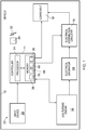
- Fig. 1 illustrates a schematic diagram of a vehicle 10 including a controller 11, a gas turbine engine 12, an electrical generator 14, electrical distribution circuitry 16, a component 18, and an input device 20.
- the vehicle 10 may be any mobile machine such as an aircraft (an airliner for example) or a watercraft (a naval vessel such as an aircraft carrier or a destroyer for example).
- the input device 20, the controller 11, and the electrical distribution circuitry 16 may form an apparatus 22 for controlling supply of electrical power to the component 18 of the vehicle 12.
- the apparatus 22 is configured to determine whether the gas turbine engine 12 has a risk of compressor surge; and where there is a risk of compressor surge, to reduce the electrical power load on the gas turbine engine.
- the apparatus 22 may be a module.
- the wording 'module' refers to a device or apparatus where one or more features are included at a later time and, possibly, by another manufacturer or by an end user.
- the apparatus 22 may only include the controller 11, and the remaining features (such as the input device 20 and the electrical distribution circuitry 16) may be added by another manufacturer, or by an end user.
- the controller 11, the input device 20, and the electrical distribution circuitry 16 may be coupled to one another via a wireless link and may consequently comprise transceiver circuitry and one or more antennas. Additionally or alternatively, the controller 11, the input device 20 and the electrical distribution circuitry 16 may be coupled to one another via a wired link and may consequently comprise interface circuitry (such as a Universal Serial Bus (USB) socket). It should be appreciated that the controller 11, the input device 20, and the electrical distribution circuitry 16 may be coupled to one another via any combination of wired and wireless links.
- USB Universal Serial Bus
- the controller 11 may comprise any suitable circuitry to cause performance of the methods described herein and as illustrated in Fig. 3 .
- the controller 11 may comprise: control circuitry; and/or processor circuitry; and/or at least one application specific integrated circuit (ASIC); and/or at least one field programmable gate array (FPGA); and/or single or multi-processor architectures; and/or sequential/parallel architectures; and/or at least one programmable logic controllers (PLCs); and/or at least one microprocessor; and/or at least one microcontroller; and/or a central processing unit (CPU); and/or a graphics processing unit (GPU), to perform the methods.
- ASIC application specific integrated circuit
- FPGA field programmable gate array
- PLCs programmable logic controllers
- microprocessor and/or at least one microcontroller
- CPU central processing unit
- GPU graphics processing unit
- the controller 11 may be mounted on the vehicle 10, or may be mounted on the gas turbine engine 12, or may be mounted at a location external to the vehicle 10 and the gas turbine engine 12 (a remote building for example). In some examples, the controller 11 may be distributed between two or more of: the vehicle 10; the gas turbine engine 12; and a location external to the vehicle 10 and the gas turbine engine 12.
- the controller 11 may comprise at least one processor 24 and at least one memory 26.
- the memory 26 stores a computer program 28 comprising computer readable instructions that, when read by the processor 24, causes performance of the methods described herein, and as illustrated in Fig. 3 .
- the computer program 28 may be software or firmware, or may be a combination of software and firmware.
- the processor 24 may be mounted on the vehicle 10, or may be mounted on the gas turbine engine 12, or may be mounted at a location external to the vehicle 10 and the gas turbine engine 12. In some examples, the processor 24 may be distributed between two or more of: the vehicle 10; the gas turbine engine 12; and a location external to the vehicle 10 and the gas turbine engine 12.
- the processor 24 may include at least one microprocessor and may comprise a single core processor, may comprise multiple processor cores (such as a dual core processor or a quad core processor), or may comprise a plurality of processors (at least one of which may comprise multiple processor cores).
- the memory 26 may be mounted on the vehicle 10, or may be mounted on the gas turbine engine 12, or may be mounted at a location external to the vehicle 10 and the gas turbine engine 12. In some examples, the memory 26 may be distributed between two or more of: the vehicle 10; the gas turbine engine 12; and a location external to the vehicle 10 and the gas turbine engine 12.
- the memory 26 may be any suitable non-transitory computer readable storage medium, data storage device or devices, and may comprise a hard disk and/or solid state memory (such as flash memory).
- the memory 26 may be permanent non-removable memory, or may be removable memory (such as a universal serial bus (USB) flash drive or a secure digital card).
- the memory 26 may include: local memory employed during actual execution of the computer program; bulk storage; and cache memories which provide temporary storage of at least some computer readable or computer usable program code to reduce the number of times code may be retrieved from bulk storage during execution of the code.
- the computer program 28 may be stored on a non-transitory computer readable storage medium 30.
- the computer program 28 may be transferred from the non-transitory computer readable storage medium 30 to the memory 26.
- the non-transitory computer readable storage medium 30 may be, for example, a USB flash drive, a secure digital (SD) card, an optical disc (such as a compact disc (CD), a digital versatile disc (DVD) or a Blu-ray disc).
- the computer program 28 may be transferred to the memory 26 via a signal 32 (such as a wireless signal or via a wired signal).
- Input/output devices may be coupled to the apparatus 22 either directly or through intervening input/output controllers.
- Various communication adaptors may also be coupled to the controller 11 to enable the apparatus 22 to become coupled to other apparatus or remote printers or storage devices through intervening private or public networks.
- Non-limiting examples include modems and network adaptors of such communication adaptors.
- the gas turbine engine 12 may be any gas turbine engine and may be, for example, a turbofan engine, a turboprop engine or a turboshaft engine. Furthermore, the gas turbine engine 12 may have any suitable internal structure.
- Fig. 2 illustrates a cross sectional side view of a gas turbine engine 12 having a principal and rotational axis 34 and comprising, in axial flow series, an air intake 36, a propulsive fan 38, an intermediate pressure compressor 40, a high-pressure compressor 42, combustion equipment 44, a high-pressure turbine 46, and intermediate pressure turbine 48, a low-pressure turbine 50, an exhaust nozzle 52 and a nacelle 54 that defines both the intake 36 and the exhaust nozzle 52.
- the gas turbine engine 12 works so that air entering the intake 36 is accelerated by the fan 38 to produce two air flows: a first air flow into the intermediate pressure compressor 40 and a second air flow which passes through a bypass duct 56 to provide propulsive thrust.
- the intermediate pressure compressor 40 compresses the air flow directed into it before delivering that air to the high pressure compressor 42 where further compression takes place.
- the compressed air exhausted from the high-pressure compressor 42 is directed into the combustion equipment 44 where it is mixed with fuel and the mixture combusted.
- the resultant hot combustion products then expand through, and thereby drive the high, intermediate and low-pressure turbines 46, 48, 50 before being exhausted through the nozzle 52 to provide additional propulsive thrust.
- the high pressure turbine 46, the intermediate pressure turbine 48 and the low pressure turbine 50 drive respectively the high pressure compressor 42, intermediate pressure compressor 40 and the fan 38, each by a suitable interconnecting shaft.
- the gas turbine engine 12 also comprises an accessory gearbox 58 that is driven by one of the interconnecting shafts (for example, the shaft interconnecting the high pressure compressor 42 and the high pressure turbine 46).
- the shafts that connect the gearbox 58 to one of the interconnecting shafts are not illustrated in Fig. 2 to maintain the clarity of the figure.
- the accessory gearbox 58 is mounted on a fan case and positioned within the nacelle 54. In other examples, the accessory gearbox 58 may be mounted on a core engine case (such as the inlet case or the intermediate case).
- gas turbine engines to which the present disclosure may be applied may have alternative configurations.
- such gas turbine engines may have an alternative number of interconnecting shafts (two for example) and/or an alternative number of compressors and/or turbines.
- the gas turbine engine 12 may not comprise a gearbox provided in the drive train from a turbine to a compressor and/or fan.
- the shaft connected to the low pressure turbine 50 does not drive the fan 38, but instead provides, or drives, an output shaft.
- the electrical generator 14 is driven by the gas turbine engine 12 and is arranged to convert mechanical power from the gas turbine engine 12 into electrical power.
- the electrical generator 14 may be driven by the accessory gearbox 58 of the gas turbine engine 12 illustrated in Fig. 2 .
- the electrical generator 14 may be driven by the output shaft of a turbofan engine.
- the electrical generator 14 may be embedded within the gas turbine engine 12 such that one of the interconnecting shafts provides, or is connected to, the rotor of the electrical generator 14.
- the electrical distribution circuitry 16 is configured to receive the electrical power output from the electrical generator 14 and to distribute the electrical power to one or more components of the vehicle 10.
- the electrical distribution circuitry 16 is configured to distribute electrical power to the component 18 of the vehicle 10.
- the electrical distribution circuitry 16 may comprise any suitable circuitry for distributing electrical power.
- the electrical distribution circuitry 16 may comprise switches, transistors, and transformers.
- the controller 11 is configured to control the operation of the electrical distribution circuitry 16.
- the controller 11 may control the electrical distribution circuitry 16 to change the electrical power distributed to the component 18 to a power between zero Watts and a maximum electrical power for that component 18.
- the component 18 may be any component (or assembly of components) of the vehicle 10 that is configured to receive electrical power from the electrical generator 14 via the electrical distribution circuitry 16.
- the component 18 may be a component of the gas turbine engine 12.
- the component 18 may comprise an electric heater 60 mounted on the inlet of the nacelle 54 for preventing ice forming on the nacelle 54.
- the electric heater 60 may be a resistive heater comprising one or more resistors.
- the component 18 may comprise a heat exchanger of the gas turbine engine 12.
- the component 18 may comprise one or more pumps of an oil system of the gas turbine engine 12.
- the component 18 may comprise an energy storage device of the gas turbine engine 12.
- the component 18 may comprise a refrigeration system of the vehicle 10 that is arranged to refrigerate or freeze food and drink for passenger consumption.
- the component 18 may comprise an energy storage device of the vehicle 10 that is arranged to store power for distributed power for propulsion systems or avionic systems (for example, refrigerant for avionic systems).
- the input device 20 may be any device that is arranged to provide a signal to the controller 11 that includes information associated with an operating condition of the gas turbine engine 12.
- the input device 20 may comprise a throttle lever for the gas turbine engine 12 that is arranged to provide a signal to the controller 11 that defines an engine throttle request.
- the input device 20 may comprise a sensor that is configured to sense the rotational speed of the high pressure compressor 42 and to provide the sensed rotational speed to the controller 11.
- the input device 20 may comprise a sensor that is configured to sense the rotational speed of the intermediate pressure compressor 40 and to provide the sensed rotational speed to the controller 11.
- the input device 20 may comprise a sensor that is configured to sense the flow of fuel supplied to the combustion equipment 44 and to provide the sensed fuel flow to the controller 11.
- the method includes receiving a signal comprising information associated with an operating condition of the gas turbine engine 12.
- the controller 11 may receive a signal from a throttle lever 20 that includes engine throttle request data.
- the controller 11 may receive a signal from a rotational speed sensor 20 that includes sensed rotational speed data of the high pressure compressor 42 or the intermediate pressure compressor 40.
- the controller 11 may receive a signal from a fuel flow sensor 20 that comprises fuel flow data.
- the method includes determining whether a parameter exceeds a predetermined threshold value using the information in the signal received at block 62. For example, the controller 11 may determine whether the requested rate of change of throttle exceeds a predetermined threshold value 66 stored in the memory 26. By way of another example, the controller 11 may determine whether a rate of change of rotational speed of the intermediate pressure compressor 40 or the high pressure compressor 42 exceeds a predetermined threshold value 68 stored in the memory 26. By way of a further example, the controller 11 may determine whether a rate of change in fuel flow exceeds a threshold value 70 stored in the memory 26. Where the parameter exceeds the predetermined threshold value, this is indicative of risk of compressor surge in the gas turbine engine 12.
- the parameter may not be a rate of change, but may be a magnitude.
- the parameter may be P30/P20, where P20 is the pressure of the air at the inlet to the compressor and P30 is the pressure of the air delivered by the compressor.
- a threshold magnitude of P30/P20 can be characterised with respect to shaft speed of the compressor.
- the method returns to block 62.
- the method moves to block 72.
- the method includes controlling a reduction in electrical power supplied to the component 18 of the vehicle 10 from the generator 14 of the gas turbine engine 12.
- the controller 11 may control the electrical distribution circuitry 16 to reduce the electrical power supplied to the component 18 (such as the heater 60 of the nacelle 54).
- the electrical power supplied to the component 18 may be reduced from P1 Watts to zero Watts (as illustrated by line 74 in Fig. 4 ).
- the electrical power supplied to the component 18 may be reduced from P1 Watts to P2 Watts (as illustrated by line 76 in Fig. 4 ).
- the method includes receiving a signal comprising information associated with an operating condition of the gas turbine engine 12.
- the controller 11 may receive a signal from the throttle lever 20 that includes engine throttle request data, or may receive a signal from a rotational speed sensor 20 that includes sensed rotational speed data of the high pressure compressor 42 or the intermediate pressure compressor 40, or may receive a signal from a fuel flow sensor 20 that comprises fuel flow data.
- the method includes determining whether a parameter exceeds a predetermined threshold value using the information in the signal received at block 78.
- the parameter at block 80 may be the same as the parameter at block 64, or may be different to the parameter at block 64.
- the controller 11 may determine whether the requested rate of change of throttle exceeds a predetermined threshold value 66 stored in the memory 26, may determine whether a rate of change of rotational speed of the intermediate pressure compressor 40 or the high pressure compressor 42 exceeds a predetermined threshold value 68 stored in the memory 26, or may determine whether a rate of change in fuel flow exceeds a threshold value 70 stored in the memory 26.
- the method moves to block 78 and the electrical power supplied to the component 18 is maintained at a low level or at zero Watts.
- the method moves to block 82.
- the method includes controlling an increase in electrical power supplied to the component 18 of the vehicle 10.
- the controller 11 may control the electrical distribution circuitry 16 to increase the electrical power supplied to the component 18 (such as the heater 60 of the nacelle 54).
- the electrical power supplied to the component 18 may be increased from zero Watts to P1 Watts (as illustrated by line 74 in Fig. 4 ).
- the electrical power supplied to the component 18 may be increased from P2 Watts to P1 Watts (as illustrated by line 76 in Fig. 4 ).
- the time between T1 and T4 may be relatively short (less than a second for example) and the latent heat in the nacelle 54 may prevent the formation of ice on the nacelle 54 between times T1 and T4.
- the apparatus 22 and the methods described in the preceding paragraphs may provide several advantages.
- the apparatus 22 and the method may reduce the risk of compressor surge in the gas turbine engine 12 during transient manoeuvres of the gas turbine engine 12. It should be appreciated that a transient manoeuvre is a desired and controlled manoeuvre of the gas turbine engine 12. A transient manoeuvre does not go beyond the limitations of the gas turbine engine 12 and therefore does not include abnormal manoeuvres such as a shaft break.
- the design of the gas turbine engine 12 may not have to take into account a high level of power off-take for adequate compressor surge margin and thus, compressor optimization may be focussed on efficiency, leading to a lower fuel burn gas turbine engine.
Landscapes
- Engineering & Computer Science (AREA)
- Chemical & Material Sciences (AREA)
- Combustion & Propulsion (AREA)
- General Engineering & Computer Science (AREA)
- Mechanical Engineering (AREA)
- Aviation & Aerospace Engineering (AREA)
- Physics & Mathematics (AREA)
- Theoretical Computer Science (AREA)
- Transportation (AREA)
- Manufacturing & Machinery (AREA)
- Computer Hardware Design (AREA)
- Evolutionary Computation (AREA)
- Geometry (AREA)
- General Physics & Mathematics (AREA)
- Engine Equipment That Uses Special Cycles (AREA)
- Supercharger (AREA)
Abstract
Description
- The present disclosure concerns methods, computer programs, non-transitory computer readable storage mediums, signals, and apparatus for controlling electrical power supplied to a component of a vehicle.
- Gas turbine engines usually comprise an electrical generator that converts mechanical power to electrical power. The generated electrical power may be supplied to components of the gas turbine engine (such as the fuel pump and the oil pump) to enable them to operate. Additionally, electrical power may be supplied to various components of a vehicle on which the gas turbine engine is mounted. For example, in an airliner, electrical power may be supplied to aircraft systems (such as cabin lighting) by the electrical generator of a gas turbine engine.
- According to a first aspect there is provided a method of controlling electrical power supplied to a component of a vehicle, the method comprising: receiving a signal comprising information associated with an operating condition of a gas turbine engine; determining whether a parameter exceeds a predetermined threshold value using the information in the received signal; and controlling a reduction in electrical power supplied to a component of a vehicle from a generator of the gas turbine engine if the parameter exceeds the predetermined threshold value.
- The parameter may be a rate of change of throttle.
- The parameter may be a rate of change in rotational speed of a rotor of the gas turbine engine.
- The parameter may be a rate of change in fuel flow.
- The component of the vehicle may be a component of the gas turbine engine.
- The component of the vehicle may comprise a heater of a nacelle.
- The component of the vehicle may comprise an energy storage device.
- Controlling reduction in electrical power supplied to the component may reduce the supply of electrical power to zero Watts.
- Controlling reduction in electrical power supplied to the component may reduce the supply of electrical power from a first electrical power level to a second electrical power level. The second electrical power level may be greater than zero Watts.
- Subsequent to a reduction in electrical power supplied to the component, the method may further comprise: determining whether a parameter exceeds a predetermined threshold value; and controlling an increase in electrical power to the component of the vehicle if the parameter does not exceed the predetermined threshold value.
- The method may be performed during a transient manoeuvre of the gas turbine engine.
- According to a second aspect there is provided a computer program that, when read by a computer, causes performance of the method as described in the preceding paragraphs.
- According to a third aspect there is provided a non-transitory computer readable storage medium comprising computer readable instructions that, when read by a computer, cause performance of the method as described in the preceding paragraphs.
- According to a fourth aspect there is provided a signal comprising computer readable instructions that, when read by a computer, cause performance of the method as described in the preceding paragraphs.
- According to a fifth aspect there is provided apparatus for controlling electrical power supplied to a component of a vehicle, the apparatus comprising a controller configured to: receive a signal comprising information associated with an operating condition of a gas turbine engine; determine whether a parameter exceeds a predetermined threshold value using the information in the received signal; and control a reduction in electrical power supplied to a component of a vehicle from a generator of the gas turbine engine if the parameter exceeds the predetermined threshold value.
- The parameter may be a rate of change of throttle.
- The parameter may be a rate of change in rotational speed of a rotor of the gas turbine engine.
- The parameter may be a rate of change in fuel flow.
- The component of the vehicle may be a component of the gas turbine engine.
- The component of the vehicle may comprise a heater of a nacelle.
- The component of the vehicle may comprise an energy storage device.
- The controller may be configured to control reduction in electrical power supplied to the component to zero Watts.
- Controlling reduction in electrical power supplied to the component may reduce the supply of electrical power from a first electrical power level to a second electrical power level. The second electrical power level may be greater than zero Watts.
- The controller may be configured to: determine whether a parameter exceeds a predetermined threshold value subsequent to a reduction in electrical power supplied to the component; and control an increase in electrical power to the component of the vehicle if the parameter does not exceed the predetermined threshold value.
- The controller may be configured to control the reduction in electrical power supplied to the component during a transient manoeuvre of the gas turbine engine.
- The skilled person will appreciate that except where mutually exclusive, a feature described in relation to any one of the above aspects may be applied mutatis mutandis to any other aspect. Furthermore except where mutually exclusive any feature described herein may be applied to any aspect and/or combined with any other feature described herein.
- Embodiments will now be described by way of example only, with reference to the Figures, in which:
-
Fig. 1 illustrates a schematic diagram of apparatus for controlling electrical power supplied to a component of a vehicle according to various examples; -
Fig. 2 illustrates a cross sectional side view of a gas turbine engine according to various examples; -
Fig. 3 illustrates a flow diagram of a method of controlling electrical power supplied to a component of a vehicle according to various examples; and -
Fig. 4 illustrates a graph of electrical power supplied to a component of a vehicle versus time according to various examples. - In the following description, the terms 'connected' and 'coupled' mean operationally connected and coupled. It should be appreciated that there may be any number of intervening components between the mentioned features, including no intervening components.
-
Fig. 1 illustrates a schematic diagram of avehicle 10 including acontroller 11, agas turbine engine 12, anelectrical generator 14,electrical distribution circuitry 16, acomponent 18, and aninput device 20. Thevehicle 10 may be any mobile machine such as an aircraft (an airliner for example) or a watercraft (a naval vessel such as an aircraft carrier or a destroyer for example). - The
input device 20, thecontroller 11, and theelectrical distribution circuitry 16 may form anapparatus 22 for controlling supply of electrical power to thecomponent 18 of thevehicle 12. In summary, theapparatus 22 is configured to determine whether thegas turbine engine 12 has a risk of compressor surge; and where there is a risk of compressor surge, to reduce the electrical power load on the gas turbine engine. - In some examples, the
apparatus 22 may be a module. As used herein, the wording 'module' refers to a device or apparatus where one or more features are included at a later time and, possibly, by another manufacturer or by an end user. For example, where theapparatus 22 is a module, theapparatus 22 may only include thecontroller 11, and the remaining features (such as theinput device 20 and the electrical distribution circuitry 16) may be added by another manufacturer, or by an end user. - The
controller 11, theinput device 20, and theelectrical distribution circuitry 16 may be coupled to one another via a wireless link and may consequently comprise transceiver circuitry and one or more antennas. Additionally or alternatively, thecontroller 11, theinput device 20 and theelectrical distribution circuitry 16 may be coupled to one another via a wired link and may consequently comprise interface circuitry (such as a Universal Serial Bus (USB) socket). It should be appreciated that thecontroller 11, theinput device 20, and theelectrical distribution circuitry 16 may be coupled to one another via any combination of wired and wireless links. - The
controller 11 may comprise any suitable circuitry to cause performance of the methods described herein and as illustrated inFig. 3 . Thecontroller 11 may comprise: control circuitry; and/or processor circuitry; and/or at least one application specific integrated circuit (ASIC); and/or at least one field programmable gate array (FPGA); and/or single or multi-processor architectures; and/or sequential/parallel architectures; and/or at least one programmable logic controllers (PLCs); and/or at least one microprocessor; and/or at least one microcontroller; and/or a central processing unit (CPU); and/or a graphics processing unit (GPU), to perform the methods. - The
controller 11 may be mounted on thevehicle 10, or may be mounted on thegas turbine engine 12, or may be mounted at a location external to thevehicle 10 and the gas turbine engine 12 (a remote building for example). In some examples, thecontroller 11 may be distributed between two or more of: thevehicle 10; thegas turbine engine 12; and a location external to thevehicle 10 and thegas turbine engine 12. - In various examples, the
controller 11 may comprise at least oneprocessor 24 and at least onememory 26. Thememory 26 stores acomputer program 28 comprising computer readable instructions that, when read by theprocessor 24, causes performance of the methods described herein, and as illustrated inFig. 3 . Thecomputer program 28 may be software or firmware, or may be a combination of software and firmware. - The
processor 24 may be mounted on thevehicle 10, or may be mounted on thegas turbine engine 12, or may be mounted at a location external to thevehicle 10 and thegas turbine engine 12. In some examples, theprocessor 24 may be distributed between two or more of: thevehicle 10; thegas turbine engine 12; and a location external to thevehicle 10 and thegas turbine engine 12. Theprocessor 24 may include at least one microprocessor and may comprise a single core processor, may comprise multiple processor cores (such as a dual core processor or a quad core processor), or may comprise a plurality of processors (at least one of which may comprise multiple processor cores). - The
memory 26 may be mounted on thevehicle 10, or may be mounted on thegas turbine engine 12, or may be mounted at a location external to thevehicle 10 and thegas turbine engine 12. In some examples, thememory 26 may be distributed between two or more of: thevehicle 10; thegas turbine engine 12; and a location external to thevehicle 10 and thegas turbine engine 12. Thememory 26 may be any suitable non-transitory computer readable storage medium, data storage device or devices, and may comprise a hard disk and/or solid state memory (such as flash memory). Thememory 26 may be permanent non-removable memory, or may be removable memory (such as a universal serial bus (USB) flash drive or a secure digital card). Thememory 26 may include: local memory employed during actual execution of the computer program; bulk storage; and cache memories which provide temporary storage of at least some computer readable or computer usable program code to reduce the number of times code may be retrieved from bulk storage during execution of the code. - The
computer program 28 may be stored on a non-transitory computerreadable storage medium 30. Thecomputer program 28 may be transferred from the non-transitory computerreadable storage medium 30 to thememory 26. The non-transitory computerreadable storage medium 30 may be, for example, a USB flash drive, a secure digital (SD) card, an optical disc (such as a compact disc (CD), a digital versatile disc (DVD) or a Blu-ray disc). In some examples, thecomputer program 28 may be transferred to thememory 26 via a signal 32 (such as a wireless signal or via a wired signal). - Input/output devices may be coupled to the
apparatus 22 either directly or through intervening input/output controllers. Various communication adaptors may also be coupled to thecontroller 11 to enable theapparatus 22 to become coupled to other apparatus or remote printers or storage devices through intervening private or public networks. Non-limiting examples include modems and network adaptors of such communication adaptors. - The
gas turbine engine 12 may be any gas turbine engine and may be, for example, a turbofan engine, a turboprop engine or a turboshaft engine. Furthermore, thegas turbine engine 12 may have any suitable internal structure. For example,Fig. 2 illustrates a cross sectional side view of agas turbine engine 12 having a principal androtational axis 34 and comprising, in axial flow series, anair intake 36, apropulsive fan 38, anintermediate pressure compressor 40, a high-pressure compressor 42,combustion equipment 44, a high-pressure turbine 46, andintermediate pressure turbine 48, a low-pressure turbine 50, anexhaust nozzle 52 and anacelle 54 that defines both theintake 36 and theexhaust nozzle 52. - The
gas turbine engine 12 works so that air entering theintake 36 is accelerated by thefan 38 to produce two air flows: a first air flow into theintermediate pressure compressor 40 and a second air flow which passes through abypass duct 56 to provide propulsive thrust. Theintermediate pressure compressor 40 compresses the air flow directed into it before delivering that air to thehigh pressure compressor 42 where further compression takes place. - The compressed air exhausted from the high-
pressure compressor 42 is directed into thecombustion equipment 44 where it is mixed with fuel and the mixture combusted. The resultant hot combustion products then expand through, and thereby drive the high, intermediate and low-pressure turbines nozzle 52 to provide additional propulsive thrust. Thehigh pressure turbine 46, theintermediate pressure turbine 48 and thelow pressure turbine 50 drive respectively thehigh pressure compressor 42,intermediate pressure compressor 40 and thefan 38, each by a suitable interconnecting shaft. - The
gas turbine engine 12 also comprises anaccessory gearbox 58 that is driven by one of the interconnecting shafts (for example, the shaft interconnecting thehigh pressure compressor 42 and the high pressure turbine 46). The shafts that connect thegearbox 58 to one of the interconnecting shafts are not illustrated inFig. 2 to maintain the clarity of the figure. Theaccessory gearbox 58 is mounted on a fan case and positioned within thenacelle 54. In other examples, theaccessory gearbox 58 may be mounted on a core engine case (such as the inlet case or the intermediate case). - Other gas turbine engines to which the present disclosure may be applied may have alternative configurations. By way of an example, such gas turbine engines may have an alternative number of interconnecting shafts (two for example) and/or an alternative number of compressors and/or turbines. Furthermore, the
gas turbine engine 12 may not comprise a gearbox provided in the drive train from a turbine to a compressor and/or fan. Additionally, where thegas turbine engine 12 is a turboshaft, the shaft connected to thelow pressure turbine 50 does not drive thefan 38, but instead provides, or drives, an output shaft. - The
electrical generator 14 is driven by thegas turbine engine 12 and is arranged to convert mechanical power from thegas turbine engine 12 into electrical power. For example, theelectrical generator 14 may be driven by theaccessory gearbox 58 of thegas turbine engine 12 illustrated inFig. 2 . In another example, theelectrical generator 14 may be driven by the output shaft of a turbofan engine. In a further example, theelectrical generator 14 may be embedded within thegas turbine engine 12 such that one of the interconnecting shafts provides, or is connected to, the rotor of theelectrical generator 14. - The
electrical distribution circuitry 16 is configured to receive the electrical power output from theelectrical generator 14 and to distribute the electrical power to one or more components of thevehicle 10. For example, theelectrical distribution circuitry 16 is configured to distribute electrical power to thecomponent 18 of thevehicle 10. Theelectrical distribution circuitry 16 may comprise any suitable circuitry for distributing electrical power. For example, theelectrical distribution circuitry 16 may comprise switches, transistors, and transformers. Thecontroller 11 is configured to control the operation of theelectrical distribution circuitry 16. For example, thecontroller 11 may control theelectrical distribution circuitry 16 to change the electrical power distributed to thecomponent 18 to a power between zero Watts and a maximum electrical power for thatcomponent 18. - The
component 18 may be any component (or assembly of components) of thevehicle 10 that is configured to receive electrical power from theelectrical generator 14 via theelectrical distribution circuitry 16. Thecomponent 18 may be a component of thegas turbine engine 12. For example, thecomponent 18 may comprise anelectric heater 60 mounted on the inlet of thenacelle 54 for preventing ice forming on thenacelle 54. Theelectric heater 60 may be a resistive heater comprising one or more resistors. By way of another example, thecomponent 18 may comprise a heat exchanger of thegas turbine engine 12. In a further example, thecomponent 18 may comprise one or more pumps of an oil system of thegas turbine engine 12. In another example, thecomponent 18 may comprise an energy storage device of thegas turbine engine 12. - In some examples, the
component 18 may comprise a refrigeration system of thevehicle 10 that is arranged to refrigerate or freeze food and drink for passenger consumption. By way of a further example, thecomponent 18 may comprise an energy storage device of thevehicle 10 that is arranged to store power for distributed power for propulsion systems or avionic systems (for example, refrigerant for avionic systems). - The
input device 20 may be any device that is arranged to provide a signal to thecontroller 11 that includes information associated with an operating condition of thegas turbine engine 12. For example, theinput device 20 may comprise a throttle lever for thegas turbine engine 12 that is arranged to provide a signal to thecontroller 11 that defines an engine throttle request. In another example, theinput device 20 may comprise a sensor that is configured to sense the rotational speed of thehigh pressure compressor 42 and to provide the sensed rotational speed to thecontroller 11. In a further example, theinput device 20 may comprise a sensor that is configured to sense the rotational speed of theintermediate pressure compressor 40 and to provide the sensed rotational speed to thecontroller 11. In another example, theinput device 20 may comprise a sensor that is configured to sense the flow of fuel supplied to thecombustion equipment 44 and to provide the sensed fuel flow to thecontroller 11. - The operation of the
apparatus 22 is described in the following paragraphs with reference toFig. 3 . - At
block 62, the method includes receiving a signal comprising information associated with an operating condition of thegas turbine engine 12. For example, thecontroller 11 may receive a signal from athrottle lever 20 that includes engine throttle request data. In another example, thecontroller 11 may receive a signal from arotational speed sensor 20 that includes sensed rotational speed data of thehigh pressure compressor 42 or theintermediate pressure compressor 40. In a further example, thecontroller 11 may receive a signal from afuel flow sensor 20 that comprises fuel flow data. - At
block 64, the method includes determining whether a parameter exceeds a predetermined threshold value using the information in the signal received atblock 62. For example, thecontroller 11 may determine whether the requested rate of change of throttle exceeds apredetermined threshold value 66 stored in thememory 26. By way of another example, thecontroller 11 may determine whether a rate of change of rotational speed of theintermediate pressure compressor 40 or thehigh pressure compressor 42 exceeds apredetermined threshold value 68 stored in thememory 26. By way of a further example, thecontroller 11 may determine whether a rate of change in fuel flow exceeds athreshold value 70 stored in thememory 26. Where the parameter exceeds the predetermined threshold value, this is indicative of risk of compressor surge in thegas turbine engine 12. - In some examples, the parameter may not be a rate of change, but may be a magnitude. For example, the parameter may be P30/P20, where P20 is the pressure of the air at the inlet to the compressor and P30 is the pressure of the air delivered by the compressor. A threshold magnitude of P30/P20 can be characterised with respect to shaft speed of the compressor.
- Where the
controller 11 determines that the parameter does not exceed thepredetermined threshold value controller 11 determines there is low risk or no risk of compressor surge), the method returns to block 62. - Where the
controller 11 determines that the parameter exceeds thepredetermined threshold value controller 11 determines there is a risk of compressor surge), the method moves to block 72. - At
block 72, the method includes controlling a reduction in electrical power supplied to thecomponent 18 of thevehicle 10 from thegenerator 14 of thegas turbine engine 12. For example (and with reference toFig. 4 ), at time T1 thecontroller 11 may control theelectrical distribution circuitry 16 to reduce the electrical power supplied to the component 18 (such as theheater 60 of the nacelle 54). In some examples, the electrical power supplied to thecomponent 18 may be reduced from P1 Watts to zero Watts (as illustrated byline 74 inFig. 4 ). In other examples, the electrical power supplied to thecomponent 18 may be reduced from P1 Watts to P2 Watts (as illustrated byline 76 inFig. 4 ). - At
block 78, the method includes receiving a signal comprising information associated with an operating condition of thegas turbine engine 12. For example, thecontroller 11 may receive a signal from thethrottle lever 20 that includes engine throttle request data, or may receive a signal from arotational speed sensor 20 that includes sensed rotational speed data of thehigh pressure compressor 42 or theintermediate pressure compressor 40, or may receive a signal from afuel flow sensor 20 that comprises fuel flow data. - At
block 80, the method includes determining whether a parameter exceeds a predetermined threshold value using the information in the signal received atblock 78. The parameter atblock 80 may be the same as the parameter atblock 64, or may be different to the parameter atblock 64. For example, thecontroller 11 may determine whether the requested rate of change of throttle exceeds apredetermined threshold value 66 stored in thememory 26, may determine whether a rate of change of rotational speed of theintermediate pressure compressor 40 or thehigh pressure compressor 42 exceeds apredetermined threshold value 68 stored in thememory 26, or may determine whether a rate of change in fuel flow exceeds athreshold value 70 stored in thememory 26. - Where the
controller 11 determines that the parameter exceeds thepredetermined threshold value controller 11 determines there is a risk of compressor surge), the method moves to block 78 and the electrical power supplied to thecomponent 18 is maintained at a low level or at zero Watts. - Where the
controller 11 determines that the parameter does not exceed thepredetermined threshold value controller 11 determines there is low risk or no risk of compressor surge), the method moves to block 82. - At
block 82, the method includes controlling an increase in electrical power supplied to thecomponent 18 of thevehicle 10. For example (and with reference toFig. 4 ), at time T3 thecontroller 11 may control theelectrical distribution circuitry 16 to increase the electrical power supplied to the component 18 (such as theheater 60 of the nacelle 54). In some examples, the electrical power supplied to thecomponent 18 may be increased from zero Watts to P1 Watts (as illustrated byline 74 inFig. 4 ). In other examples, the electrical power supplied to thecomponent 18 may be increased from P2 Watts to P1 Watts (as illustrated byline 76 inFig. 4 ). - It should be appreciated that where the
component 18 comprises theheater 60 of thenacelle 54, the time between T1 and T4 may be relatively short (less than a second for example) and the latent heat in thenacelle 54 may prevent the formation of ice on thenacelle 54 between times T1 and T4. - The
apparatus 22 and the methods described in the preceding paragraphs may provide several advantages. - First, the
apparatus 22 and the method may reduce the risk of compressor surge in thegas turbine engine 12 during transient manoeuvres of thegas turbine engine 12. It should be appreciated that a transient manoeuvre is a desired and controlled manoeuvre of thegas turbine engine 12. A transient manoeuvre does not go beyond the limitations of thegas turbine engine 12 and therefore does not include abnormal manoeuvres such as a shaft break. - Second, the design of the
gas turbine engine 12 may not have to take into account a high level of power off-take for adequate compressor surge margin and thus, compressor optimization may be focussed on efficiency, leading to a lower fuel burn gas turbine engine. - It will be understood that the invention is not limited to the embodiments above-described and various modifications and improvements can be made without departing from the concepts described herein. For example, the different embodiments may take the form of an entirely hardware embodiment, an entirely software embodiment, or an embodiment containing both hardware and software elements.
- Except where mutually exclusive, any of the features may be employed separately or in combination with any other features and the disclosure extends to and includes all combinations and sub-combinations of one or more features described herein.
Claims (13)
- A method of controlling electrical power supplied to a component of a vehicle, the method comprising:receiving a signal comprising information associated with an operating condition of a gas turbine engine;determining whether a parameter exceeds a predetermined threshold value using the information in the received signal; andcontrolling a reduction in electrical power supplied to a component of a vehicle from a generator of the gas turbine engine if the parameter exceeds the predetermined threshold value.
- A method as claimed in claim 1, wherein the parameter is a rate of change of throttle.
- A method as claimed in claim 1, wherein the parameter is a rate of change in rotational speed of a rotor of the gas turbine engine.
- A method as claimed in claim 1, wherein the parameter is a rate of change in fuel flow.
- A method as claimed in any of the preceding claims, wherein the component of the vehicle is a component of the gas turbine engine.
- A method as claimed in any of the preceding claims, wherein the component of the vehicle comprises a heater of a nacelle.
- A method as claimed in any of the preceding claims, wherein the component of the vehicle comprises an energy storage device.
- A method as claimed in any of the preceding claims, wherein controlling reduction in electrical power supplied to the component reduces the supply of electrical power to zero Watts.
- A method as claimed in any of claims 1 to 7, wherein controlling reduction in electrical power supplied to the component reduces the supply of electrical power from a first electrical power level to a second electrical power level, the second electrical power level being greater than zero Watts.
- A method as claimed in any of the preceding claims, wherein subsequent to a reduction in electrical power supplied to the component, the method further comprises: determining whether a parameter exceeds a predetermined threshold value; and controlling an increase in electrical power to the component of the vehicle if the parameter does not exceed the predetermined threshold value.
- A method as claimed in any of the preceding claims, wherein the method is performed during a transient manoeuvre of the gas turbine engine.
- A computer program that, when read by a computer, causes performance of the method as claimed in any of the preceding claims.
- Apparatus for controlling electrical power supplied to a component of a vehicle, the apparatus comprising a controller configured to perform a method as claimed in any of claims 1 to 11.
Applications Claiming Priority (1)
| Application Number | Priority Date | Filing Date | Title |
|---|---|---|---|
| GBGB1721389.3A GB201721389D0 (en) | 2017-12-20 | 2017-12-20 | Methods, computer programs, non-transitory computer readable storage mediums, signals, and apparatus for controlling electrical power supplied to a component |
Publications (2)
| Publication Number | Publication Date |
|---|---|
| EP3502444A1 true EP3502444A1 (en) | 2019-06-26 |
| EP3502444B1 EP3502444B1 (en) | 2021-04-21 |
Family
ID=61009171
Family Applications (1)
| Application Number | Title | Priority Date | Filing Date |
|---|---|---|---|
| EP18207297.5A Active EP3502444B1 (en) | 2017-12-20 | 2018-11-20 | Methods and apparatus for controlling electrical power supplied to a component of a vehicle |
Country Status (4)
| Country | Link |
|---|---|
| US (1) | US11015525B2 (en) |
| EP (1) | EP3502444B1 (en) |
| CN (1) | CN110043366B (en) |
| GB (1) | GB201721389D0 (en) |
Families Citing this family (6)
| Publication number | Priority date | Publication date | Assignee | Title |
|---|---|---|---|---|
| US10227137B2 (en) * | 2016-03-22 | 2019-03-12 | Ge Aviation Systems Llc | Hybrid power system for an aircraft |
| US20220097864A1 (en) * | 2020-09-30 | 2022-03-31 | Ge Avio S.R.L. | Aircraft performance optimization based on engine performance monitoring |
| US11530617B2 (en) | 2020-10-26 | 2022-12-20 | Antheon Research, Inc. | Gas turbine propulsion system |
| US11002146B1 (en) | 2020-10-26 | 2021-05-11 | Antheon Research, Inc. | Power generation system |
| US11975847B2 (en) | 2022-03-16 | 2024-05-07 | General Electric Company | Ice protection systems for aircraft |
| US12365466B1 (en) | 2024-01-23 | 2025-07-22 | General Electric Company | Power switching system of an anti-ice system for use with a main power supply and an auxiliary power supply |
Citations (4)
| Publication number | Priority date | Publication date | Assignee | Title |
|---|---|---|---|---|
| EP2657457A2 (en) * | 2012-04-27 | 2013-10-30 | IHI Aerospace Co., Ltd. | Electricity generation system |
| EP2881563A1 (en) * | 2013-12-06 | 2015-06-10 | Rolls-Royce Corporation | Integrated electrical power and thermal management system |
| EP2942679A2 (en) * | 2014-04-29 | 2015-11-11 | The Boeing Company | Systems and methods for the control and operation of a parallel motor controller architecture |
| EP3130783A1 (en) * | 2015-08-14 | 2017-02-15 | General Electric Company | Gas turbine engine stall margin management |
Family Cites Families (12)
| Publication number | Priority date | Publication date | Assignee | Title |
|---|---|---|---|---|
| US5499497A (en) | 1993-08-06 | 1996-03-19 | Simmonds Precision Engine Systems | Temperature detector and control for an igniter |
| US6487847B1 (en) * | 2000-11-03 | 2002-12-03 | General Electric Company | Gas turbine engine fuel control system |
| EP1787019A1 (en) * | 2004-08-27 | 2007-05-23 | Optimum Power Technology, L.P. | Predictive engine combustion management |
| DE102007035927A1 (en) * | 2007-07-31 | 2009-02-05 | Mtu Aero Engines Gmbh | Control for a gas turbine with actively stabilized compressor |
| JP2009145219A (en) | 2007-12-14 | 2009-07-02 | Denso Corp | NOx sensor diagnostic device for internal combustion engine |
| FR2941439B1 (en) * | 2009-01-28 | 2011-01-14 | Aircelle Sa | ELECTRIC DEFROSTING DEVICE AND CONTROL SYSTEM THEREFOR |
| US8355854B2 (en) * | 2009-05-08 | 2013-01-15 | General Electric Company | Methods relating to gas turbine control and operation |
| JP5799642B2 (en) | 2011-08-01 | 2015-10-28 | 株式会社Ihi | Fuel supply system for gas turbine engines |
| US9217412B2 (en) | 2012-04-29 | 2015-12-22 | LGT Advanced Technology Limited | Wind energy system and method for using same |
| US9255525B2 (en) * | 2012-11-30 | 2016-02-09 | General Electric Company | System and method for gas turbine operation |
| JP6173367B2 (en) * | 2015-02-03 | 2017-08-02 | 三菱日立パワーシステムズ株式会社 | State determination device, operation control device, gas turbine, and state determination method |
| US9810113B2 (en) * | 2015-03-09 | 2017-11-07 | The Boeing Company | Engine lubrication heating system |
-
2017
- 2017-12-20 GB GBGB1721389.3A patent/GB201721389D0/en not_active Ceased
-
2018
- 2018-11-20 EP EP18207297.5A patent/EP3502444B1/en active Active
- 2018-12-06 US US16/211,360 patent/US11015525B2/en active Active
- 2018-12-20 CN CN201811563694.4A patent/CN110043366B/en not_active Expired - Fee Related
Patent Citations (4)
| Publication number | Priority date | Publication date | Assignee | Title |
|---|---|---|---|---|
| EP2657457A2 (en) * | 2012-04-27 | 2013-10-30 | IHI Aerospace Co., Ltd. | Electricity generation system |
| EP2881563A1 (en) * | 2013-12-06 | 2015-06-10 | Rolls-Royce Corporation | Integrated electrical power and thermal management system |
| EP2942679A2 (en) * | 2014-04-29 | 2015-11-11 | The Boeing Company | Systems and methods for the control and operation of a parallel motor controller architecture |
| EP3130783A1 (en) * | 2015-08-14 | 2017-02-15 | General Electric Company | Gas turbine engine stall margin management |
Also Published As
| Publication number | Publication date |
|---|---|
| US20190186360A1 (en) | 2019-06-20 |
| CN110043366B (en) | 2023-04-07 |
| CN110043366A (en) | 2019-07-23 |
| GB201721389D0 (en) | 2018-01-31 |
| EP3502444B1 (en) | 2021-04-21 |
| US11015525B2 (en) | 2021-05-25 |
Similar Documents
| Publication | Publication Date | Title |
|---|---|---|
| US11015525B2 (en) | Methods, computer programs, non transitory computer readable storage mediums, signals, and apparatus for controlling electrical power supplied to a component of a vehicle | |
| CN111894740B (en) | System and method for transmitting mechanical power in a turbine engine | |
| JP6313756B2 (en) | Optimized power transmission method and structure between helicopter auxiliary power motor and main engine | |
| EP2987961B1 (en) | Gas turbine engine system and corresponding method | |
| US10337409B2 (en) | Method for assisting a turboshaft engine in standby of a multiple-engine helicopter, and architecture of a propulsion system of a helicopter comprising at least one turboshaft engine that can be in standby | |
| US11549464B2 (en) | Hybrid gas turbine engine starting control | |
| US9091216B2 (en) | Systems and methods for changing a speed of a compressor boost stage in a gas turbine | |
| US10100744B2 (en) | Aircraft bleed air and engine starter systems and related methods | |
| CN106574574A (en) | Hybrid compressors for turbojet engines | |
| CN103195582A (en) | Engine systems with enhanced start control schedules | |
| US20160319745A1 (en) | Controller modulated oil system for a gas turbine propulsion system | |
| EP2949876B1 (en) | System and method to manage engine transients for rapid power demand changes | |
| EP4345268A1 (en) | A thermoelectric generator system and method | |
| EP4345267B1 (en) | A gas turbine engine | |
| US20230138476A1 (en) | Hybrid electric single engine descent restart |
Legal Events
| Date | Code | Title | Description |
|---|---|---|---|
| PUAI | Public reference made under article 153(3) epc to a published international application that has entered the european phase |
Free format text: ORIGINAL CODE: 0009012 |
|
| STAA | Information on the status of an ep patent application or granted ep patent |
Free format text: STATUS: THE APPLICATION HAS BEEN PUBLISHED |
|
| AK | Designated contracting states |
Kind code of ref document: A1 Designated state(s): AL AT BE BG CH CY CZ DE DK EE ES FI FR GB GR HR HU IE IS IT LI LT LU LV MC MK MT NL NO PL PT RO RS SE SI SK SM TR |
|
| AX | Request for extension of the european patent |
Extension state: BA ME |
|
| STAA | Information on the status of an ep patent application or granted ep patent |
Free format text: STATUS: REQUEST FOR EXAMINATION WAS MADE |
|
| 17P | Request for examination filed |
Effective date: 20191218 |
|
| RBV | Designated contracting states (corrected) |
Designated state(s): AL AT BE BG CH CY CZ DE DK EE ES FI FR GB GR HR HU IE IS IT LI LT LU LV MC MK MT NL NO PL PT RO RS SE SI SK SM TR |
|
| RAP1 | Party data changed (applicant data changed or rights of an application transferred) |
Owner name: ROLLS-ROYCE PLC |
|
| STAA | Information on the status of an ep patent application or granted ep patent |
Free format text: STATUS: EXAMINATION IS IN PROGRESS |
|
| 17Q | First examination report despatched |
Effective date: 20200421 |
|
| GRAP | Despatch of communication of intention to grant a patent |
Free format text: ORIGINAL CODE: EPIDOSNIGR1 |
|
| STAA | Information on the status of an ep patent application or granted ep patent |
Free format text: STATUS: GRANT OF PATENT IS INTENDED |
|
| INTG | Intention to grant announced |
Effective date: 20210120 |
|
| GRAS | Grant fee paid |
Free format text: ORIGINAL CODE: EPIDOSNIGR3 |
|
| GRAA | (expected) grant |
Free format text: ORIGINAL CODE: 0009210 |
|
| STAA | Information on the status of an ep patent application or granted ep patent |
Free format text: STATUS: THE PATENT HAS BEEN GRANTED |
|
| AK | Designated contracting states |
Kind code of ref document: B1 Designated state(s): AL AT BE BG CH CY CZ DE DK EE ES FI FR GB GR HR HU IE IS IT LI LT LU LV MC MK MT NL NO PL PT RO RS SE SI SK SM TR |
|
| REG | Reference to a national code |
Ref country code: GB Ref legal event code: FG4D |
|
| REG | Reference to a national code |
Ref country code: CH Ref legal event code: EP |
|
| REG | Reference to a national code |
Ref country code: DE Ref legal event code: R096 Ref document number: 602018015791 Country of ref document: DE Ref country code: IE Ref legal event code: FG4D |
|
| REG | Reference to a national code |
Ref country code: AT Ref legal event code: REF Ref document number: 1384864 Country of ref document: AT Kind code of ref document: T Effective date: 20210515 |
|
| REG | Reference to a national code |
Ref country code: LT Ref legal event code: MG9D |
|
| REG | Reference to a national code |
Ref country code: AT Ref legal event code: MK05 Ref document number: 1384864 Country of ref document: AT Kind code of ref document: T Effective date: 20210421 |
|
| REG | Reference to a national code |
Ref country code: NL Ref legal event code: MP Effective date: 20210421 |
|
| PG25 | Lapsed in a contracting state [announced via postgrant information from national office to epo] |
Ref country code: HR Free format text: LAPSE BECAUSE OF FAILURE TO SUBMIT A TRANSLATION OF THE DESCRIPTION OR TO PAY THE FEE WITHIN THE PRESCRIBED TIME-LIMIT Effective date: 20210421 Ref country code: LT Free format text: LAPSE BECAUSE OF FAILURE TO SUBMIT A TRANSLATION OF THE DESCRIPTION OR TO PAY THE FEE WITHIN THE PRESCRIBED TIME-LIMIT Effective date: 20210421 Ref country code: FI Free format text: LAPSE BECAUSE OF FAILURE TO SUBMIT A TRANSLATION OF THE DESCRIPTION OR TO PAY THE FEE WITHIN THE PRESCRIBED TIME-LIMIT Effective date: 20210421 Ref country code: NL Free format text: LAPSE BECAUSE OF FAILURE TO SUBMIT A TRANSLATION OF THE DESCRIPTION OR TO PAY THE FEE WITHIN THE PRESCRIBED TIME-LIMIT Effective date: 20210421 Ref country code: AT Free format text: LAPSE BECAUSE OF FAILURE TO SUBMIT A TRANSLATION OF THE DESCRIPTION OR TO PAY THE FEE WITHIN THE PRESCRIBED TIME-LIMIT Effective date: 20210421 Ref country code: BG Free format text: LAPSE BECAUSE OF FAILURE TO SUBMIT A TRANSLATION OF THE DESCRIPTION OR TO PAY THE FEE WITHIN THE PRESCRIBED TIME-LIMIT Effective date: 20210721 |
|
| PG25 | Lapsed in a contracting state [announced via postgrant information from national office to epo] |
Ref country code: SE Free format text: LAPSE BECAUSE OF FAILURE TO SUBMIT A TRANSLATION OF THE DESCRIPTION OR TO PAY THE FEE WITHIN THE PRESCRIBED TIME-LIMIT Effective date: 20210421 Ref country code: RS Free format text: LAPSE BECAUSE OF FAILURE TO SUBMIT A TRANSLATION OF THE DESCRIPTION OR TO PAY THE FEE WITHIN THE PRESCRIBED TIME-LIMIT Effective date: 20210421 Ref country code: NO Free format text: LAPSE BECAUSE OF FAILURE TO SUBMIT A TRANSLATION OF THE DESCRIPTION OR TO PAY THE FEE WITHIN THE PRESCRIBED TIME-LIMIT Effective date: 20210721 Ref country code: PT Free format text: LAPSE BECAUSE OF FAILURE TO SUBMIT A TRANSLATION OF THE DESCRIPTION OR TO PAY THE FEE WITHIN THE PRESCRIBED TIME-LIMIT Effective date: 20210823 Ref country code: PL Free format text: LAPSE BECAUSE OF FAILURE TO SUBMIT A TRANSLATION OF THE DESCRIPTION OR TO PAY THE FEE WITHIN THE PRESCRIBED TIME-LIMIT Effective date: 20210421 Ref country code: LV Free format text: LAPSE BECAUSE OF FAILURE TO SUBMIT A TRANSLATION OF THE DESCRIPTION OR TO PAY THE FEE WITHIN THE PRESCRIBED TIME-LIMIT Effective date: 20210421 Ref country code: IS Free format text: LAPSE BECAUSE OF FAILURE TO SUBMIT A TRANSLATION OF THE DESCRIPTION OR TO PAY THE FEE WITHIN THE PRESCRIBED TIME-LIMIT Effective date: 20210821 Ref country code: GR Free format text: LAPSE BECAUSE OF FAILURE TO SUBMIT A TRANSLATION OF THE DESCRIPTION OR TO PAY THE FEE WITHIN THE PRESCRIBED TIME-LIMIT Effective date: 20210722 |
|
| REG | Reference to a national code |
Ref country code: DE Ref legal event code: R097 Ref document number: 602018015791 Country of ref document: DE |
|
| PG25 | Lapsed in a contracting state [announced via postgrant information from national office to epo] |
Ref country code: SM Free format text: LAPSE BECAUSE OF FAILURE TO SUBMIT A TRANSLATION OF THE DESCRIPTION OR TO PAY THE FEE WITHIN THE PRESCRIBED TIME-LIMIT Effective date: 20210421 Ref country code: SK Free format text: LAPSE BECAUSE OF FAILURE TO SUBMIT A TRANSLATION OF THE DESCRIPTION OR TO PAY THE FEE WITHIN THE PRESCRIBED TIME-LIMIT Effective date: 20210421 Ref country code: ES Free format text: LAPSE BECAUSE OF FAILURE TO SUBMIT A TRANSLATION OF THE DESCRIPTION OR TO PAY THE FEE WITHIN THE PRESCRIBED TIME-LIMIT Effective date: 20210421 Ref country code: EE Free format text: LAPSE BECAUSE OF FAILURE TO SUBMIT A TRANSLATION OF THE DESCRIPTION OR TO PAY THE FEE WITHIN THE PRESCRIBED TIME-LIMIT Effective date: 20210421 Ref country code: RO Free format text: LAPSE BECAUSE OF FAILURE TO SUBMIT A TRANSLATION OF THE DESCRIPTION OR TO PAY THE FEE WITHIN THE PRESCRIBED TIME-LIMIT Effective date: 20210421 Ref country code: CZ Free format text: LAPSE BECAUSE OF FAILURE TO SUBMIT A TRANSLATION OF THE DESCRIPTION OR TO PAY THE FEE WITHIN THE PRESCRIBED TIME-LIMIT Effective date: 20210421 Ref country code: DK Free format text: LAPSE BECAUSE OF FAILURE TO SUBMIT A TRANSLATION OF THE DESCRIPTION OR TO PAY THE FEE WITHIN THE PRESCRIBED TIME-LIMIT Effective date: 20210421 |
|
| PLBE | No opposition filed within time limit |
Free format text: ORIGINAL CODE: 0009261 |
|
| STAA | Information on the status of an ep patent application or granted ep patent |
Free format text: STATUS: NO OPPOSITION FILED WITHIN TIME LIMIT |
|
| 26N | No opposition filed |
Effective date: 20220124 |
|
| PG25 | Lapsed in a contracting state [announced via postgrant information from national office to epo] |
Ref country code: IS Free format text: LAPSE BECAUSE OF FAILURE TO SUBMIT A TRANSLATION OF THE DESCRIPTION OR TO PAY THE FEE WITHIN THE PRESCRIBED TIME-LIMIT Effective date: 20210821 Ref country code: AL Free format text: LAPSE BECAUSE OF FAILURE TO SUBMIT A TRANSLATION OF THE DESCRIPTION OR TO PAY THE FEE WITHIN THE PRESCRIBED TIME-LIMIT Effective date: 20210421 |
|
| PG25 | Lapsed in a contracting state [announced via postgrant information from national office to epo] |
Ref country code: MC Free format text: LAPSE BECAUSE OF FAILURE TO SUBMIT A TRANSLATION OF THE DESCRIPTION OR TO PAY THE FEE WITHIN THE PRESCRIBED TIME-LIMIT Effective date: 20210421 |
|
| REG | Reference to a national code |
Ref country code: CH Ref legal event code: PL |
|
| PG25 | Lapsed in a contracting state [announced via postgrant information from national office to epo] |
Ref country code: LU Free format text: LAPSE BECAUSE OF NON-PAYMENT OF DUE FEES Effective date: 20211120 Ref country code: IT Free format text: LAPSE BECAUSE OF FAILURE TO SUBMIT A TRANSLATION OF THE DESCRIPTION OR TO PAY THE FEE WITHIN THE PRESCRIBED TIME-LIMIT Effective date: 20210421 Ref country code: BE Free format text: LAPSE BECAUSE OF NON-PAYMENT OF DUE FEES Effective date: 20211130 |
|
| REG | Reference to a national code |
Ref country code: BE Ref legal event code: MM Effective date: 20211130 |
|
| PG25 | Lapsed in a contracting state [announced via postgrant information from national office to epo] |
Ref country code: LI Free format text: LAPSE BECAUSE OF NON-PAYMENT OF DUE FEES Effective date: 20211130 Ref country code: CH Free format text: LAPSE BECAUSE OF NON-PAYMENT OF DUE FEES Effective date: 20211130 |
|
| PG25 | Lapsed in a contracting state [announced via postgrant information from national office to epo] |
Ref country code: IE Free format text: LAPSE BECAUSE OF NON-PAYMENT OF DUE FEES Effective date: 20211120 |
|
| PG25 | Lapsed in a contracting state [announced via postgrant information from national office to epo] |
Ref country code: CY Free format text: LAPSE BECAUSE OF FAILURE TO SUBMIT A TRANSLATION OF THE DESCRIPTION OR TO PAY THE FEE WITHIN THE PRESCRIBED TIME-LIMIT Effective date: 20210421 |
|
| P01 | Opt-out of the competence of the unified patent court (upc) registered |
Effective date: 20230528 |
|
| PG25 | Lapsed in a contracting state [announced via postgrant information from national office to epo] |
Ref country code: HU Free format text: LAPSE BECAUSE OF FAILURE TO SUBMIT A TRANSLATION OF THE DESCRIPTION OR TO PAY THE FEE WITHIN THE PRESCRIBED TIME-LIMIT; INVALID AB INITIO Effective date: 20181120 |
|
| PGFP | Annual fee paid to national office [announced via postgrant information from national office to epo] |
Ref country code: GB Payment date: 20231121 Year of fee payment: 6 |
|
| PGFP | Annual fee paid to national office [announced via postgrant information from national office to epo] |
Ref country code: FR Payment date: 20231123 Year of fee payment: 6 Ref country code: DE Payment date: 20231127 Year of fee payment: 6 |
|
| PG25 | Lapsed in a contracting state [announced via postgrant information from national office to epo] |
Ref country code: MK Free format text: LAPSE BECAUSE OF FAILURE TO SUBMIT A TRANSLATION OF THE DESCRIPTION OR TO PAY THE FEE WITHIN THE PRESCRIBED TIME-LIMIT Effective date: 20210421 |
|
| PG25 | Lapsed in a contracting state [announced via postgrant information from national office to epo] |
Ref country code: MT Free format text: LAPSE BECAUSE OF FAILURE TO SUBMIT A TRANSLATION OF THE DESCRIPTION OR TO PAY THE FEE WITHIN THE PRESCRIBED TIME-LIMIT Effective date: 20210421 |
|
| REG | Reference to a national code |
Ref country code: DE Ref legal event code: R119 Ref document number: 602018015791 Country of ref document: DE |
|
| GBPC | Gb: european patent ceased through non-payment of renewal fee |
Effective date: 20241120 |
|
| PG25 | Lapsed in a contracting state [announced via postgrant information from national office to epo] |
Ref country code: DE Free format text: LAPSE BECAUSE OF NON-PAYMENT OF DUE FEES Effective date: 20250603 |
|
| PG25 | Lapsed in a contracting state [announced via postgrant information from national office to epo] |
Ref country code: GB Free format text: LAPSE BECAUSE OF NON-PAYMENT OF DUE FEES Effective date: 20241120 |
|
| PG25 | Lapsed in a contracting state [announced via postgrant information from national office to epo] |
Ref country code: FR Free format text: LAPSE BECAUSE OF NON-PAYMENT OF DUE FEES Effective date: 20241130 |
|
| PG25 | Lapsed in a contracting state [announced via postgrant information from national office to epo] |
Ref country code: TR Free format text: LAPSE BECAUSE OF FAILURE TO SUBMIT A TRANSLATION OF THE DESCRIPTION OR TO PAY THE FEE WITHIN THE PRESCRIBED TIME-LIMIT Effective date: 20210421 |