EP3502440B1 - Gas turbine engine component assembly - Google Patents
Gas turbine engine component assembly Download PDFInfo
- Publication number
- EP3502440B1 EP3502440B1 EP18215269.4A EP18215269A EP3502440B1 EP 3502440 B1 EP3502440 B1 EP 3502440B1 EP 18215269 A EP18215269 A EP 18215269A EP 3502440 B1 EP3502440 B1 EP 3502440B1
- Authority
- EP
- European Patent Office
- Prior art keywords
- component
- gas turbine
- airflow
- combustor
- passageway
- Prior art date
- Legal status (The legal status is an assumption and is not a legal conclusion. Google has not performed a legal analysis and makes no representation as to the accuracy of the status listed.)
- Active
Links
Images



Classifications
-
- F—MECHANICAL ENGINEERING; LIGHTING; HEATING; WEAPONS; BLASTING
- F23—COMBUSTION APPARATUS; COMBUSTION PROCESSES
- F23R—GENERATING COMBUSTION PRODUCTS OF HIGH PRESSURE OR HIGH VELOCITY, e.g. GAS-TURBINE COMBUSTION CHAMBERS
- F23R3/00—Continuous combustion chambers using liquid or gaseous fuel
- F23R3/002—Wall structures
-
- F—MECHANICAL ENGINEERING; LIGHTING; HEATING; WEAPONS; BLASTING
- F02—COMBUSTION ENGINES; HOT-GAS OR COMBUSTION-PRODUCT ENGINE PLANTS
- F02C—GAS-TURBINE PLANTS; AIR INTAKES FOR JET-PROPULSION PLANTS; CONTROLLING FUEL SUPPLY IN AIR-BREATHING JET-PROPULSION PLANTS
- F02C7/00—Features, components parts, details or accessories, not provided for in, or of interest apart form groups F02C1/00 - F02C6/00; Air intakes for jet-propulsion plants
- F02C7/12—Cooling of plants
- F02C7/16—Cooling of plants characterised by cooling medium
- F02C7/18—Cooling of plants characterised by cooling medium the medium being gaseous, e.g. air
- F02C7/185—Cooling means for reducing the temperature of the cooling air or gas
-
- F—MECHANICAL ENGINEERING; LIGHTING; HEATING; WEAPONS; BLASTING
- F23—COMBUSTION APPARATUS; COMBUSTION PROCESSES
- F23M—CASINGS, LININGS, WALLS OR DOORS SPECIALLY ADAPTED FOR COMBUSTION CHAMBERS, e.g. FIREBRIDGES; DEVICES FOR DEFLECTING AIR, FLAMES OR COMBUSTION PRODUCTS IN COMBUSTION CHAMBERS; SAFETY ARRANGEMENTS SPECIALLY ADAPTED FOR COMBUSTION APPARATUS; DETAILS OF COMBUSTION CHAMBERS, NOT OTHERWISE PROVIDED FOR
- F23M5/00—Casings; Linings; Walls
- F23M5/08—Cooling thereof; Tube walls
-
- F—MECHANICAL ENGINEERING; LIGHTING; HEATING; WEAPONS; BLASTING
- F23—COMBUSTION APPARATUS; COMBUSTION PROCESSES
- F23R—GENERATING COMBUSTION PRODUCTS OF HIGH PRESSURE OR HIGH VELOCITY, e.g. GAS-TURBINE COMBUSTION CHAMBERS
- F23R3/00—Continuous combustion chambers using liquid or gaseous fuel
-
- F—MECHANICAL ENGINEERING; LIGHTING; HEATING; WEAPONS; BLASTING
- F23—COMBUSTION APPARATUS; COMBUSTION PROCESSES
- F23R—GENERATING COMBUSTION PRODUCTS OF HIGH PRESSURE OR HIGH VELOCITY, e.g. GAS-TURBINE COMBUSTION CHAMBERS
- F23R3/00—Continuous combustion chambers using liquid or gaseous fuel
- F23R3/02—Continuous combustion chambers using liquid or gaseous fuel characterised by the air-flow or gas-flow configuration
- F23R3/04—Air inlet arrangements
- F23R3/045—Air inlet arrangements using pipes
-
- F—MECHANICAL ENGINEERING; LIGHTING; HEATING; WEAPONS; BLASTING
- F23—COMBUSTION APPARATUS; COMBUSTION PROCESSES
- F23R—GENERATING COMBUSTION PRODUCTS OF HIGH PRESSURE OR HIGH VELOCITY, e.g. GAS-TURBINE COMBUSTION CHAMBERS
- F23R3/00—Continuous combustion chambers using liquid or gaseous fuel
- F23R3/02—Continuous combustion chambers using liquid or gaseous fuel characterised by the air-flow or gas-flow configuration
- F23R3/04—Air inlet arrangements
- F23R3/06—Arrangement of apertures along the flame tube
-
- F—MECHANICAL ENGINEERING; LIGHTING; HEATING; WEAPONS; BLASTING
- F05—INDEXING SCHEMES RELATING TO ENGINES OR PUMPS IN VARIOUS SUBCLASSES OF CLASSES F01-F04
- F05D—INDEXING SCHEME FOR ASPECTS RELATING TO NON-POSITIVE-DISPLACEMENT MACHINES OR ENGINES, GAS-TURBINES OR JET-PROPULSION PLANTS
- F05D2240/00—Components
- F05D2240/35—Combustors or associated equipment
-
- F—MECHANICAL ENGINEERING; LIGHTING; HEATING; WEAPONS; BLASTING
- F05—INDEXING SCHEMES RELATING TO ENGINES OR PUMPS IN VARIOUS SUBCLASSES OF CLASSES F01-F04
- F05D—INDEXING SCHEME FOR ASPECTS RELATING TO NON-POSITIVE-DISPLACEMENT MACHINES OR ENGINES, GAS-TURBINES OR JET-PROPULSION PLANTS
- F05D2260/00—Function
- F05D2260/20—Heat transfer, e.g. cooling
- F05D2260/201—Heat transfer, e.g. cooling by impingement of a fluid
-
- F—MECHANICAL ENGINEERING; LIGHTING; HEATING; WEAPONS; BLASTING
- F05—INDEXING SCHEMES RELATING TO ENGINES OR PUMPS IN VARIOUS SUBCLASSES OF CLASSES F01-F04
- F05D—INDEXING SCHEME FOR ASPECTS RELATING TO NON-POSITIVE-DISPLACEMENT MACHINES OR ENGINES, GAS-TURBINES OR JET-PROPULSION PLANTS
- F05D2260/00—Function
- F05D2260/60—Fluid transfer
- F05D2260/607—Preventing clogging or obstruction of flow paths by dirt, dust, or foreign particles
-
- F—MECHANICAL ENGINEERING; LIGHTING; HEATING; WEAPONS; BLASTING
- F23—COMBUSTION APPARATUS; COMBUSTION PROCESSES
- F23R—GENERATING COMBUSTION PRODUCTS OF HIGH PRESSURE OR HIGH VELOCITY, e.g. GAS-TURBINE COMBUSTION CHAMBERS
- F23R2900/00—Special features of, or arrangements for continuous combustion chambers; Combustion processes therefor
- F23R2900/00004—Preventing formation of deposits on surfaces of gas turbine components, e.g. coke deposits
-
- F—MECHANICAL ENGINEERING; LIGHTING; HEATING; WEAPONS; BLASTING
- F23—COMBUSTION APPARATUS; COMBUSTION PROCESSES
- F23R—GENERATING COMBUSTION PRODUCTS OF HIGH PRESSURE OR HIGH VELOCITY, e.g. GAS-TURBINE COMBUSTION CHAMBERS
- F23R2900/00—Special features of, or arrangements for continuous combustion chambers; Combustion processes therefor
- F23R2900/03044—Impingement cooled combustion chamber walls or subassemblies
-
- Y—GENERAL TAGGING OF NEW TECHNOLOGICAL DEVELOPMENTS; GENERAL TAGGING OF CROSS-SECTIONAL TECHNOLOGIES SPANNING OVER SEVERAL SECTIONS OF THE IPC; TECHNICAL SUBJECTS COVERED BY FORMER USPC CROSS-REFERENCE ART COLLECTIONS [XRACs] AND DIGESTS
- Y02—TECHNOLOGIES OR APPLICATIONS FOR MITIGATION OR ADAPTATION AGAINST CLIMATE CHANGE
- Y02T—CLIMATE CHANGE MITIGATION TECHNOLOGIES RELATED TO TRANSPORTATION
- Y02T50/00—Aeronautics or air transport
- Y02T50/60—Efficient propulsion technologies, e.g. for aircraft
Definitions
- the size of the gap 760 may varied to produce a desired pressure drop to obtain a desired amount of airflow 590 through the gap 760 in order to generate a desired lateral airflow 590a in the impingement cavity.
- the size of the gap 760 may be increased and/or decreased.
- a combustor of a gas turbine engine is used for illustrative purposes and the embodiments disclosed herein may be applicable to additional components of other than a combustor of a gas turbine engine, such as, for example, a first component and a second component defining a cooling channel therebetween.
- the first component may have cooling holes similar to the primary orifices. The cooling holes may direct air through the cooling channel to impinge upon the second component.
Landscapes
- Engineering & Computer Science (AREA)
- Chemical & Material Sciences (AREA)
- Combustion & Propulsion (AREA)
- Mechanical Engineering (AREA)
- General Engineering & Computer Science (AREA)
- Turbine Rotor Nozzle Sealing (AREA)
Description
- The subject matter disclosed herein generally relates to gas turbine engines and, more particularly, to a method and apparatus for mitigating particulate accumulation on cooling surfaces of components of gas turbine engines.
- In one example, a combustor of a gas turbine engine may be configured and required to burn fuel in a minimum volume. Such configurations may place substantial heat load on the structure of the combustor (e.g., panels, shell, etc.). Such heat loads may dictate that special consideration is given to structures, which may be configured as heat shields or panels, and to the cooling of such structures to protect these structures. Excess temperatures at these structures may lead to oxidation, cracking, and high thermal stresses of the heat shields or panels. Particulates in the air used to cool these structures may inhibit cooling of the heat shield and reduce durability. Particulates, in particular atmospheric particulates, include solid or liquid matter suspended in the atmosphere such as dust, ice, ash, sand and dirt.
-
WO 2015085080 discloses a turbine engine assembly with a combustor wall which includes a shell, a heat shield and an annular body, wherein an igniter aperture is defined in the combustor wall and the shell defines a cooling aperture. - A gas turbine engine component assembly according to the preamble of claim 1 is known from
US 2016/0238253 A1 . - According to the invention a gas turbine engine component assembly is provided.
- The gas turbine engine component comprises: a first component having a first surface, a second surface opposite the first surface, a cooling hole extending from the second surface to the first surface through the first component, and a receiving aperture extending from the second surface to the first surface through the first component; a second component having a first surface and a second surface, the first surface of the first component and the second surface of the second component defining cooling channel therebetween in fluid communication with the cooling hole for cooling the second surface of the second component; and a passageway portion including a first end, a second end opposite the first end, and an outer surface extending from the second end to the first end, the passageway portion extending from the second surface of the second component through the cooling channel and through the receiving aperture of the first component, wherein the outer surface of the passageway portion and the receiving aperture of the first component define a gap therebetween, the gap fluidly connecting airflow in an airflow path proximate the second surface of the first component to the cooling channel, wherein the gap is configured to direct the airflow along the outer surface of the passageway portion and the outer surface of the passageway portion is shaped to redirect the airflow in a lateral direction parallel to the second surface of the second component such that a lateral airflow is generated in the cooling channel. The gas turbine engine component further comprises an intermittent circumferential ring located in the cooling channel and partially circumferentially surrounding the outer surface of the passageway portion, wherein the intermittent circumferential ring is configured to direct the lateral airflow in a selected lateral direction.
- Further embodiments may include that the passageway portion is tubular in shape.
- Further embodiments may include that the passageway portion includes a passageway enclosed with the passageway portion, the passageway fluidly connecting the airflow in the flow path proximate the second surface of the first component to a chamber located proximate the first surface of the second component.
- Further embodiments may include that the intermittent circumferential ring extends from the second surface of the second component to proximate the first surface of the first component.
- Further embodiments may include that the second component further includes cooling holes fluidly connecting the cooling channel to a chamber located proximate the first surface of the second component.
- Further embodiments may include: a flat portion of the outer surface of the passageway portion, the flat portion oriented parallel with the second surface of the second component within the cooling channel.
- Further embodiments may include that the flat portion is oriented perpendicular to the gap.
- Further embodiments may include: a flat portion of the outer surface is oriented parallel with the second surface of the second component within the cooling channel, wherein the flat portion is located radially inward of the intermittent circumferential ring.
- Further embodiments may include that the flat portion is oriented perpendicular to the gap.
- Further embodiments may include that the first component is a combustion liner of a combustor for use in a gas turbine engine; the first surface of the first component is an inner surface of the combustion liner; the second surface of the first component is an outer surface of the combustion liner; the cooling hole of the first component is a primary aperture; the second component is a heat shield panel of the combustor; and the cooling channel is an impingement cavity of the combustor.
- According to another embodiment, a combustor for use in a gas turbine engine is provided. The combustor encloses a combustion chamber having a combustion area, wherein the combustor comprises the gas turbine engine component assembly according to the invention, wherein the first component is a combustion liner of the combustor; the first surface of the first component is an inner surface of the combustion liner; the second surface of the first component is an outer surface of the combustion liner; the cooling hole of the first component is a primary aperture; the second component is a heat shield panel of the combustor; and the cooling channel is an impingement cavity of the combustor.
- Further embodiments may include that the passageway portion is tubular in shape.
- Further embodiments may include that the passageway portion includes a passageway enclosed with the passageway portion, the passageway fluidly connecting the airflow in the flow path proximate the outer surface of the combustion liner to the combustion area.
- Further embodiments may include that the intermittent circumferential ring extends from the second surface of the heat shield panel to proximate the inner surface of the combustion liner.
- Further embodiments may include that the heat shield panel further includes secondary apertures fluidly connecting the impingement cavity to the combustion area.
- Further embodiments may include: a flat portion of the outer surface of the passageway portion, the flat portion oriented parallel with the outer surface of the heat shield panel within the impingement cavity.
- Further embodiments may include that the flat portion is oriented perpendicular to the gap.
- Further embodiments may include: a flat portion of the outer surface of the passageway portion is oriented parallel with the second surface of the heat shield panel within the impingement cavity, wherein the flat portion is located radially inward of the intermittent circumferential ring.
- The foregoing features and elements may be combined in various combinations without exclusivity, unless expressly indicated otherwise. These features and elements as well as the operation thereof will become more apparent in light of the following description and the accompanying drawings. It should be understood, however, that the following description and drawings are intended to be illustrative and explanatory in nature and non-limiting.
- The following descriptions should not be considered limiting in any way. With reference to the accompanying drawings, like elements are numbered alike:
-
FIG. 1 is a partial cross-sectional illustration of a gas turbine engine, in accordance with an embodiment of the disclosure; -
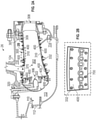
FIG. 2A is a cross-sectional illustration of a combustor, in accordance with an embodiment of the disclosure; -
FIG. 2B is an enlarged illustration of quench holes of a combustor, in accordance with an embodiment of the disclosure; -
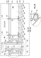
FIG. 3A is an enlarged cross-sectional illustration of a heat shield panel, combustion liner, and a quench hole of a combustor, in accordance with an embodiment of the disclosure; -
FIG. 3B is an enlarged three-dimensional view illustration of a heat shield panel and a quench hole of a combustor, in accordance with an embodiment of the disclosure; -
FIG. 4A is an enlarged cross-sectional illustration of a heat shield panel, combustion liner, and a quench hole of a combustor, in accordance with an embodiment of the disclosure; -
FIG. 4B is an enlarged three-dimensional view illustration of a heat shield panel and a quench hole of a combustor, in accordance with an embodiment of the disclosure; -
FIG. 5A is an enlarged three-dimensional view illustration of a heat shield panel and multiple cooling holes of a combustor, in accordance with an embodiment of the disclosure; -
FIG. 5B is an enlarged cross-sectional illustration of a heat shield panel, combustion liner, and a quench hole of a combustor, in accordance with an embodiment of the disclosure; and -
FIG. 5C is an enlarged cross-sectional illustration of a heat shield panel, combustion liner, and a quench hole of a combustor, in accordance with an embodiment of the disclosure. - The detailed description explains embodiments of the present disclosure, together with advantages and features, by way of example with reference to the drawings.
- A detailed description of one or more embodiments of the disclosed apparatus and method are presented herein by way of exemplification and not limitation with reference to the Figures.
- Combustors of gas turbine engines, as well as other components, experience elevated heat levels during operation. Impingement and convective cooling of panels of the combustor wall may be used to help cool the combustor. Convective cooling may be achieved by air that is channeled between the panels and a liner of the combustor. Impingement cooling may be a process of directing relatively cool air from a location exterior to the combustor toward a back or underside of the panels.
- Thus, combustion liners and heat shield panels are utilized to face the hot products of combustion within a combustion chamber and protect the overall combustor shell. The combustion liners may be supplied with cooling air including dilution passages which deliver a high volume of cooling air into a hot flow path. The cooling air may be air from the compressor of the gas turbine engine. The cooling air may impinge upon a back side of a heat shield panel that faces a combustion liner inside the combustor. The cooling air may contain particulates, which may build up on the heat shield panels overtime, thus reducing the cooling ability of the cooling air. Embodiments disclosed herein seek to address particulate adherence to the heat shield panels in order to maintain the cooling ability of the cooling air.
-
FIG. 1 schematically illustrates agas turbine engine 20. Thegas turbine engine 20 is disclosed herein as a two-spool turbofan that generally incorporates afan section 22, acompressor section 24, acombustor section 26 and aturbine section 28. Alternative engines might include an augmentor section (not shown) among other systems or features. Thefan section 22 drives air along a bypass flow path B in a bypass duct, while thecompressor section 24 drives air along a core flow path C for compression and communication into thecombustor section 26 then expansion through theturbine section 28. Although depicted as a two-spool turbofan gas turbine engine in the disclosed non-limiting embodiment, it should be understood that the concepts described herein are not limited to use with two-spool turbofans as the teachings may be applied to other types of turbine engines including three-spool architectures. - The
exemplary engine 20 generally includes alow speed spool 30 and ahigh speed spool 32 mounted for rotation about an engine central longitudinal axis A relative to an enginestatic structure 36 viaseveral bearing systems 38. It should be understood that various bearingsystems 38 at various locations may alternatively or additionally be provided, and the location of bearingsystems 38 may be varied as appropriate to the application. - The
low speed spool 30 generally includes aninner shaft 40 that interconnects afan 42, alow pressure compressor 44 and alow pressure turbine 46. Theinner shaft 40 is connected to thefan 42 through a speed change mechanism, which in exemplarygas turbine engine 20 is illustrated as a gearedarchitecture 48 to drive thefan 42 at a lower speed than thelow speed spool 30. Thehigh speed spool 32 includes anouter shaft 50 that interconnects ahigh pressure compressor 52 andhigh pressure turbine 54. Acombustor 300 is arranged inexemplary gas turbine 20 between thehigh pressure compressor 52 and thehigh pressure turbine 54. An enginestatic structure 36 is arranged generally between thehigh pressure turbine 54 and thelow pressure turbine 46. The enginestatic structure 36 furthersupports bearing systems 38 in theturbine section 28. Theinner shaft 40 and theouter shaft 50 are concentric and rotate via bearingsystems 38 about the engine central longitudinal axis A which is collinear with their longitudinal axes. - The core airflow is compressed by the
low pressure compressor 44 then thehigh pressure compressor 52, mixed and burned with fuel in thecombustor 300, then expanded over thehigh pressure turbine 54 andlow pressure turbine 46. Theturbines low speed spool 30 andhigh speed spool 32 in response to the expansion. It will be appreciated that each of the positions of thefan section 22,compressor section 24,combustor section 26,turbine section 28, and fandrive gear system 48 may be varied. For example,gear system 48 may be located aft ofcombustor section 26 or even aft ofturbine section 28, andfan section 22 may be positioned forward or aft of the location ofgear system 48. - The
engine 20 in one example is a high-bypass geared aircraft engine. In a further example, theengine 20 bypass ratio is greater than about six (6), with an example embodiment being greater than about ten (10), the gearedarchitecture 48 is an epicyclic gear train, such as a planetary gear system or other gear system, with a gear reduction ratio of greater than about 2.3 and thelow pressure turbine 46 has a pressure ratio that is greater than about five. In one disclosed embodiment, theengine 20 bypass ratio is greater than about ten (10:1), the fan diameter is significantly larger than that of thelow pressure compressor 44, and thelow pressure turbine 46 has a pressure ratio that is greater than about five 5:1.Low pressure turbine 46 pressure ratio is pressure measured prior to inlet oflow pressure turbine 46 as related to the pressure at the outlet of thelow pressure turbine 46 prior to an exhaust nozzle. The gearedarchitecture 48 may be an epicycle gear train, such as a planetary gear system or other gear system, with a gear reduction ratio of greater than about 2.3:1. It should be understood, however, that the above parameters are only exemplary of one embodiment of a geared architecture engine and that the present disclosure is applicable to other gas turbine engines including direct drive turbofans. - A significant amount of thrust is provided by the bypass flow B due to the high bypass ratio. The
fan section 22 of theengine 20 is designed for a particular flight condition--typically cruise at about 0.8Mach and about 35,000 feet (10,688 meters). The flight condition of 0.8 Mach and 35,000 ft (10,688 meters), with the engine at its best fuel consumption--also known as "bucket cruise Thrust Specific Fuel Consumption ('TSFC')"--is the industry standard parameter of lbm of fuel being burned divided by lbf of thrust the engine produces at that minimum point. "Low fan pressure ratio" is the pressure ratio across the fan blade alone, without a Fan Exit Guide Vane ("FEGV") system. The low fan pressure ratio as disclosed herein according to one non-limiting embodiment is less than about 1.45. "Low corrected fan tip speed" is the actual fan tip speed in ft/sec divided by an industry standard temperature correction of [(Tram °R)/(518.7 °R)]0.5. The "Low corrected fan tip speed" as disclosed herein according to one non-limiting embodiment is less than about 1150 ft/second (350.5 m/sec). - Referring now to
FIGs. 2A-B and with continued reference toFIG. 1 , thecombustor section 26 of thegas turbine engine 20 is shown. As illustrated, acombustor 300 defines acombustion chamber 302. Thecombustion chamber 302 includes acombustion area 370 within thecombustion chamber 302. Thecombustor 300 includes aninlet 306 and anoutlet 308 through which air may pass. The air may be supplied to thecombustor 300 by a pre-diffuser 110. Air may also enter thecombustion chamber 302 through other holes in thecombustor 300 including but not limited to quenchholes 700, as seen inFIGs. 2A-B . - Compressor air is supplied from the
compressor section 24 into apre-diffuser strut 112. As will be appreciated by those of skill in the art, thepre-diffuser strut 112 is configured to direct the airflow into the pre-diffuser 110, which then directs the airflow toward thecombustor 300. Thecombustor 300 and the pre-diffuser 110 are separated by ashroud chamber 113 that contains thecombustor 300 and includes aninner diameter branch 114 and anouter diameter branch 116. As air enters theshroud chamber 113, a portion of the air may flow into thecombustor inlet 306, a portion may flow into theinner diameter branch 114, and a portion may flow into theouter diameter branch 116. - The air from the
inner diameter branch 114 and theouter diameter branch 116 may then enter thecombustion chamber 302 by means of one or moreprimary apertures 307 in thecombustion liner 600 and one or moresecondary apertures 309 in theheat shield panels 400. Theprimary apertures 307 andsecondary apertures 309 may include nozzles, holes, etc. The air may then exit thecombustion chamber 302 through thecombustor outlet 308. At the same time, fuel may be supplied into thecombustion chamber 302 from afuel injector 320 and apilot nozzle 322, which may be ignited within thecombustion chamber 302. Thecombustor 300 of theengine combustion section 26 may be housed within ashroud case 124 which may define theshroud chamber 113. - The
combustor 300, as shown inFIG. 2A , includes multipleheat shield panels 400 that are attached to the combustion liner 600 (SeeFIG. 3A ). Theheat shield panels 400 may be arranged parallel to thecombustion liner 600. Thecombustion liner 600 can define circular or annular structures with theheat shield panels 400 being mounted on a radially inward liner and a radially outward liner, as will be appreciated by those of skill in the art. Theheat shield panels 400 can be removably mounted to thecombustion liner 600 by one ormore attachment mechanisms 332. In some embodiments, theattachment mechanism 332 may be integrally formed with a respectiveheat shield panel 400, although other configurations are possible. In some embodiments, theattachment mechanism 332 may be a bolt or other structure that may extend from the respectiveheat shield panel 400 through the interior surface to a receiving portion or aperture of thecombustion liner 600 such that theheat shield panel 400 may be attached to thecombustion liner 600 and held in place. Theheat shield panels 400 partially enclose acombustion area 370 within thecombustion chamber 302 of thecombustor 300. - Referring now to
FIGs. 3A-B and4A-B , with continued reference toFIGs. 1 and2A-B .FIG. 3A illustrates aheat shield panel 400,combustion liner 600 of a combustor 300 (seeFIG. 1 ) of a gas turbine engine 20 (seeFIG. 1 ), and a quenchhole 700 to attached theheat shield panel 400 to thecombustion liner 600. Theheat shield panel 400 and thecombustion liner 600 are in a facing spaced relationship. The quenchhole 700 is a cooling hole to provide cooled air to thecombustion area 370 of thecombustion chamber 302. Theheat shield panel 400 includes afirst surface 410 oriented towards thecombustion area 370 of thecombustion chamber 302 and asecond surface 420 first surface opposite thefirst surface 410 oriented towards thecombustion liner 600. Thecombustion liner 600 is having aninner surface 610 and anouter surface 620 opposite theinner surface 610. Theinner surface 610 is oriented toward theheat shield panel 400. Theouter surface 620 is oriented outward from thecombustor 300 proximate theinner diameter branch 114 and theouter diameter branch 116. - The
combustion liner 600 includes a plurality ofprimary apertures 307 configured to allowairflow 590 from theinner diameter branch 114 and theouter diameter branch 116 to enter animpingement cavity 390 in between thecombustion liner 600 and theheat shield panel 400. Each of theprimary apertures 307 extend from theouter surface 620 to theinner surface 610 through thecombustion liner 600. - Each of the
primary apertures 307 fluidly connects theimpingement cavity 390 to at least one of theinner diameter branch 114 and theouter diameter branch 116. Theheat shield panel 400 may include one or moresecondary apertures 309 configured to allowairflow 590 from theimpingement cavity 390 to thecombustion area 370combustion chamber 302. - Each of the
secondary apertures 309 extend from thesecond surface 420 to thefirst surface 410 through theheat shield panel 400.Airflow 590 flowing into theimpingement cavity 390 impinges on thesecond surface 420 of theheat shield panel 400 and absorbs heat from theheat shield panel 400 as it impinges on thesecond surface 420. As seen inFIG. 3A , particulate 592 may accompany theairflow 590 flowing into theimpingement cavity 390.Particulate 592 may include but is not limited to dirt, smoke, soot, volcanic ash, or similar airborne particulate known to one of skill in the art. As theairflow 590 and particulate 592 impinge upon thesecond surface 420 of theheat shield panel 400, the particulate 592 may begin to collect on thesecond surface 420, as seen inFIG. 3A .Particulate 592 collecting upon thesecond surface 420 of theheat shield panel 400 reduces the cooling efficiency ofairflow 590 impinging upon thesecond surface 420 and thus may increase local temperatures of theheat shield panel 400 and thecombustion liner 600.Particulate 592 collection upon thesecond surface 420 of theheat shield panel 400 may potentially create ablockage 593 to thesecondary apertures 309 in theheat shield panels 400, thus reducingairflow 590 into thecombustion area 370 of thecombustion chamber 302. Theblockage 593 may be a partial blockage or a full blockage. - A conventional quench
hole 700 is also illustrated inFIGs. 3A-B . The quenchhole 700 includes apassageway portion 720 and achannel portion 740. Thepassageway portion 720 and thechannel portion 740 may be referred to together as a grommet. - Although illustrated as a separate attachment to the
heat shield panel 400 inFIGs. 3A-B and4A-B , thepassageway portion 720 and thechannel portion 740 may be integrally formed from theheat shield panel 400. InFIG. 3A , thepassageway portion 720 extends from thefirst surface 410 of theheat shield panel 400 through theimpingement cavity 390 through a receivingaperture 725 of thecombustion liner 600. Agap 760 exists between anouter surface 734 of thepassageway portion 720 and the receivingaperture 725. Thepassageway portion 720 includes afirst end 724 and asecond end 726 opposite thefirst end 724. Thefirst end 724 is located proximateheat shield panel 400. Anoutlet 728 is located at thefirst end 724. Theouter surface 734 extends from thesecond end 726 to thefirst end 724 proximate theheat shield panel 400. Theouter surface 734 stretches across thepassageway portion 720 and the channel portion 710. Apassageway 722 of thepassageway portion 720 fluidly connects thecombustion area 370 to theshroud chamber 113, theinner diameter branch 114, and/or theouter diameter branch 116. Thepassageway 722 is fluidly connected to thecombustions chamber 302 through theoutlet 728. - The
passageway portion 720 of the quenchhole 700 conveysairflow 590 in an airflow path D proximate theouter surface 620 of thecombustion liner 600 directly to thecombustion area 370. Thesecond end 726 includes anoutlet 732 and the outlet is located in the airflow path D. Theoutlet 732 fluidly connects thepassageway 722 toairflow 590 in the airflowpath D. Airflow 590 in the airflow path D may originate from theshroud chamber 113, theinner diameter branch 114, and/or theouter diameter branch 116, as described above. Thepassageway portion 720 passes through theimpingement cavity 390 but does not fluidly connect to theimpingement cavity 390. As illustrated inFIG. 3A , thepassageway portion 720 may be tubal in shape. - The
channel portion 740 fluidly connects theimpingement cavity 390 to theshroud chamber 113, theinner diameter branch 114, and/or theouter diameter branch 116. Thechannel portion 740 of the quenchhole 700 conveysairflow 590 in an airflow path D proximate theouter surface 620 of thecombustion liner 600 into thechannel 744 and then through a dedicatedsecondary aperture 309a into thecombustion area 370. Thededicated aperture 309a fluidly connects thechannel 744 to thecombustion area 370.Airflow 590 in the airflow path D may originate from theshroud chamber 113, theinner diameter branch 114, and/or theouter diameter branch 116, as described above. Thechannel portion 740 includes an outercircumferential ring 746 configured to seal against the inward surface of thecombustion liner 600 in order to prevent air leakage from thechannel 744 to theimpingement cavity 390. As illustrated inFIG. 3A , thechannel portion 740 may be tubal in shape and located radially outward from thepassageway portion 720. The outercircumferential ring 746 is located radially outward from thepassageway portion 720 and thechannel 744 is created therebetween.Airflow 590 is conveyed to thechannel 744 through agap 760 that exists between theouter surface 734 of thepassageway portion 720 and thecombustion liner 600 at the receivingaperture 725. The size of thegap 760 may varied to produce a desired pressure drop to obtain a desired amount ofairflow 590 through thegap 760 in order to generate a desiredlateral airflow 590a in the impingement cavity. The size of thegap 760 may be increased and/or decreased. - A different configuration of a quench
hole 700 is illustrated inFIGs. 4A-B , in accordance with an embodiment of the present disclosure. The quenchhole 700 includes apassageway portion 720 and achannel portion 740 but thecircumferential ring 746 is partially removed in selected locations, thus creating an intermittentcircumferential ring 746a. The intermittentcircumferential ring 746a only partially circumferentially surrounds the passageway portion 720 (i.e. there are cut-outs in the intermittentcircumferential ring 746a), thus creating an incomplete seal with theinner surface 610 of thecombustion liner 600, which allowsairflow 590 from thechannel 744 to be flow into theimpingement cavity 390. Advantageously, since thecircumferential ring 746 only partially circumferentially surrounds thepassageway portion 720, when the air leaves thechannel 744 and flows into theimpingement cavity 390 alateral airflow 590a is generated thus promoting lateral movement ofparticulate 592 through theimpingement cavity 390, thus reducing the amount ofparticulate 592 collecting on thesecond surface 420 of theheat shield panel 400, as seen inFIG. 4A . Also advantageously, if theimpingement cavity 390 includes anexit 390a, since thecircumferential ring 746 only partially circumferentially surrounds thepassageway portion 720, when the air leaves thechannel 744 and flows into theimpingement cavity 390 alateral airflow 590a is generated thus promoting lateral movement ofparticulate 592 through theimpingement cavity 390 and towards theexit 390a of theimpingement cavity 390. - In
FIG. 4A , thepassageway portion 720 extends from thefirst surface 410 of theheat shield panel 400 through theimpingement cavity 390 through a receivingaperture 725 of thecombustion liner 600. Agap 760 exists between anouter surface 734 of thepassageway portion 720 and the receivingaperture 725. Thepassageway portion 720 includes afirst end 724 and asecond end 726 opposite thefirst end 724. Thefirst end 724 is located proximateheat shield panel 400. Anoutlet 728 is located at thefirst end 724. Theouter surface 734 extends from thesecond end 726 tofirst end 724 proximate theheat shield panel 400. Theouter surface 734 stretches across thepassageway portion 720 and the channel portion 710. Apassageway 722 of thepassageway portion 720 fluidly connects thecombustion area 370 to theshroud chamber 113, theinner diameter branch 114, and/or theouter diameter branch 116. Thepassageway portion 720 of the quenchhole 700 conveysairflow 590 in an airflow path D proximate theouter surface 620 of thecombustion liner 600 directly to thecombustion area 370. Thesecond end 726 includes anoutlet 732 and the outlet is located in the airflow path D. Theoutlet 732 fluidly connects thepassageway 722 toairflow 590 in the airflowpath D. Airflow 590 in the airflow path D may originate from theshroud chamber 113, theinner diameter branch 114, and/or theouter diameter branch 116, as described above. Thepassageway portion 720 passes through theimpingement cavity 390 but does not fluidly connect to theimpingement cavity 390. As illustrated inFIG. 3B , thepassageway portion 720 may be tubal in shape. - In
FIG. 4A , thechannel portion 740 fluidly connects theimpingement cavity 390 to theshroud chamber 113, theinner diameter branch 114, and/or theouter diameter branch 116. Thechannel portion 740 of the quenchhole 700 conveysairflow 590 in an airflow path D proximate theouter surface 620 of thecombustion liner 600 into thechannel 744 and then through a dedicatedsecondary aperture 309a into thecombustion area 370. Thededicated aperture 309a fluidly connects thechannel 744 to thecombustion area 370.Airflow 590 in the airflow path D may originate from theshroud chamber 113, theinner diameter branch 114, and/or theouter diameter branch 116, as described above. Thechannel portion 740 includes an intermittent outercircumferential ring 746a configured to partially seal against the inward surface of thecombustion liner 600 in order to prevent air leakage from thechannel 744 to theimpingement cavity 390 in particular directions. Advantageously, through utilization of an intermittent outercircumferential ring 726, theairflow 590 leakage into theimpingement cavity 390 may be directed in a selected direction. As illustrated inFIG. 4A , thechannel portion 740 may be tubal in shape and located radially outward from thepassageway portion 720. The outer intermittentcircumferential ring 746a is located radially outward from thepassageway portion 720 and thechannel 744 is created therebetween.Airflow 590 is conveyed to thechannel 744 through agap 760 that exists between theouter surface 734 of thepassageway portion 720 and thecombustion liner 600 at the receivingaperture 725. The size of thegap 760 may varied to produce a desired pressure drop to obtain a desired amount ofairflow 590 through thegap 760 in order to generate a desiredlateral airflow 590a in the impingement cavity. The size of thegap 760 may be increased and/or decreased. Thegap 760 is configured to direct theairflow 590 along theouter surface 734 of thepassageway portion 720 and theouter surface 734 is shaped to redirect theairflow 590 in about a lateral direction XI such that across flow 590a is generated in theimpingement cavity 390. As shown inFIG. 4A , theouter surface 734 may include aflat portion 736 oriented about parallel with thesecond surface 420 of theheat shield panel 400 within theimpingement cavity 390. Theflat portion 736 is configured to redirect theairflow 590 in about a lateral direction XI such that across flow 590a is generated in theimpingement cavity 390. Theflat portion 736 is located radially inward of the intermittentcircumferential ring 746a. - As illustrated in
FIG. 5A-C ,additional cooling holes heat shield panel 400. These cooling holes 800, 900 include apassageway portion channel portion 740 as described above in reference toFIGs. 3A-B and4A-B . Thepassageway portion first surface 410 of theheat shield panel 400 through theimpingement cavity 390 through a receivingaperture 725 of thecombustion liner 600. Agap 760 exists between anouter surface passageway portion aperture 725. Thepassageway portion first end second end first end first end heat shield panel 400. Anoutlet 828, 928 is located at thefirst end outer surface second end first end heat shield panel 400. Apassageway passageway portion combustion area 370 to theshroud chamber 113, theinner diameter branch 114, and/or theouter diameter branch 116. Thepassageway portion airflow 590 in an airflow path D proximate theouter surface 620 of thecombustion liner 600 directly to thecombustion area 370. - The
second end outlet outlet outlet passageway airflow 590 in the airflowpath D. Airflow 590 in the airflow path D may originate from theshroud chamber 113, theinner diameter branch 114, and/or theouter diameter branch 116, as described above. Thepassageway portion impingement cavity 390 but does not fluidly connect to theimpingement cavity 390. As illustrated inFIG. 5B , thepassageway portion Airflow 590 is conveyed to theimpingement cavity 390 through agap 760 that exists between theouter surface passageway portion combustion liner 600 at the receivingaperture 725. The size of thegap 760 may varied to produce a desired pressure drop to obtain a desired amount ofairflow 590 through thegap 760 in order to generate a desiredlateral airflow 590a in the impingement cavity. The size of thegap 760 may be increased and/or decreased. Thegap 760 is configured to direct theairflow 590 along theouter surface passageway portion outer surface airflow 590 in about a lateral direction X1 such that across flow 590a is generated in theimpingement cavity 390. As shown inFIG. 5A-B , theouter surface flat portion second surface 420 of theheat shield panel 400 within theimpingement cavity 390. Theflat portion airflow 590 in about a lateral direction XI such that across flow 590a is generated in theimpingement cavity 390. - It is understood that a combustor of a gas turbine engine is used for illustrative purposes and the embodiments disclosed herein may be applicable to additional components of other than a combustor of a gas turbine engine, such as, for example, a first component and a second component defining a cooling channel therebetween. The first component may have cooling holes similar to the primary orifices. The cooling holes may direct air through the cooling channel to impinge upon the second component.
- Technical effects of embodiments of the present disclosure include incorporating directing airflow along a passageway portion of a cooling hole and redirecting the airflow laterally to introduce lateral airflow across a heat shield panel surrounding a combustion area of a combustion chamber to help reduce collection of particulates on the heat shield panel and also help to reduce entry of the particulate into the combustion area of a combustion chamber.
- The term "about" is intended to include the degree of error associated with measurement of the particular quantity based upon the equipment available at the time of filing the application. For example, "about" can include a non-limiting range of ± 8% or 5%, or 2% of a given value.
- The terminology used herein is for the purpose of describing particular embodiments only and is not intended to be limiting of the present disclosure. As used herein, the singular forms "a", "an" and "the" are intended to include the plural forms as well, unless the context clearly indicates otherwise. It will be further understood that the terms "comprises" and/or "comprising," when used in this specification, specify the presence of stated features, integers, steps, operations, elements, and/or components, but do not preclude the presence or addition of one or more other features, integers, steps, operations, element components, and/or groups thereof.
- While the present disclosure has been described with reference to an exemplary embodiment or embodiments, it will be understood by those skilled in the art that various changes may be made and equivalents may be substituted for elements thereof without departing from the scope of the present disclosure. In addition, many modifications may be made to adapt a particular situation or material to the teachings of the present disclosure without departing from the essential scope thereof. Therefore, it is intended that the present disclosure not be limited to the particular embodiment disclosed as the best mode contemplated for carrying out this present disclosure, but that the present disclosure will include all embodiments falling within the scope of the claims.
Claims (11)
- A gas turbine engine component assembly, comprising:a first component (600) having a first surface (610), a second surface (620) opposite the first surface, a cooling hole (307) extending from the second surface to the first surface through the first component, and a receiving aperture (725) extending from the second surface to the first surface through the first component;a second component (400) having a first surface (410) and a second surface (420), the first surface of the first component and the second surface of the second component defining a cooling channel therebetween in fluid communication with the cooling hole for cooling the second surface of the second component; anda passageway portion (720) including a first end (724), a second end (726) opposite the first end, and an outer surface (734) extending from the second end to the first end, the passageway portion extending from the second surface of the second component through the cooling channel and through the receiving aperture of the first component,whereinthe outer surface of the passageway portion and the receiving aperture of the first component define a gap (760) therebetween, the gap fluidly connecting airflow (590) in an airflow path (D) proximate the second surface of the first component to the cooling channel, wherein the gap is configured to direct the airflow along the outer surface of the passageway portion and the outer surface of the passageway portion is shaped to redirect the airflow in a lateral direction (XI) parallel to the second surface of the second component such that a lateral airflow (590a) is generated in the coolingchannel,characterized in thatthe gas turbine engine component assembly further comprises an intermittent circumferential ring (746a) located in the cooling channel and partially circumferentially surrounding the outer surface (734) of the passageway portion (720), wherein the intermittent circumferential ring is configured to direct the lateral airflow in a selected lateral direction.
- The gas turbine engine component assembly of claim 1, wherein the passageway portion (720) is tubular in shape.
- The gas turbine engine component assembly of claim 1 or claim 2, wherein the passageway portion (720) includes a passageway enclosed with the passageway portion, the passageway fluidly connecting the airflow in the flow path proximate the second surface (620) of the first component (600) to a chamber located proximate the first surface (410) of the second component (400).
- The gas turbine engine component assembly of any preceding claim, wherein:
the intermittent circumferential ring (746a) extends from the second surface (420) of the second component (400) to proximate the first surface (610) of the first component (600). - The gas turbine engine component assembly of any preceding claim, wherein:
the second component (400) further includes cooling holes (800; 900) fluidly connecting the cooling channel to a chamber located proximate the first surface (410) of the second component (400). - The gas turbine engine component assembly of claim 1, further comprising:
a flat portion (736) of the outer surface (734) of the passageway portion (720), the flat portion oriented parallel with the second surface (420) of the second component (400) within the cooling channel. - The gas turbine component assembly according to claim 6, wherein the flat portion (736) is oriented perpendicular to the gap (760).
- The gas turbine component assembly according to any of claims 4 to 6, further comprising:
a flat portion (736) of the outer surface (734) is oriented parallel with the second surface (420) of the second component (400) within the cooling channel, wherein the flat portion is located radially inward of the intermittent circumferential ring (746a). - The gas turbine component assembly according to claim 8, wherein the flat portion (736) is oriented perpendicular to the gap (760).
- A combustor (300) for use in a gas turbine engine (20), the combustor enclosing a combustion chamber (302) having a combustion area (370), wherein the combustor comprises:the gas turbine engine component assembly of any preceding claim, whereinthe first component (600) is a combustion liner of the combustor;the first surface (610) of the first component is an inner surface of the combustion liner;the second surface (620) of the first component is an outer surface of the combustion liner;the cooling hole (700) of the first component is a primary aperture;the second component (400) is a heat shield panel of the combustor; andthe cooling channel is an impingement cavity (390) of the combustor.
- The combustor of claim 10, further comprising a grommet, the grommet comprising:the passageway portion (720); anda channel portion (740) surrounding the passageway portion and adapted to receive the combustion liner (600),wherein the channel portion has at least one cut-out to introduce a cross flow into the impingement cavity (390) defined between the combustion liner and the heat shield panel (400).
Applications Claiming Priority (1)
| Application Number | Priority Date | Filing Date | Title |
|---|---|---|---|
| US201762609574P | 2017-12-22 | 2017-12-22 |
Publications (2)
| Publication Number | Publication Date |
|---|---|
| EP3502440A1 EP3502440A1 (en) | 2019-06-26 |
| EP3502440B1 true EP3502440B1 (en) | 2022-03-16 |
Family
ID=64901870
Family Applications (1)
| Application Number | Title | Priority Date | Filing Date |
|---|---|---|---|
| EP18215269.4A Active EP3502440B1 (en) | 2017-12-22 | 2018-12-21 | Gas turbine engine component assembly |
Country Status (2)
| Country | Link |
|---|---|
| US (1) | US11143401B2 (en) |
| EP (1) | EP3502440B1 (en) |
Families Citing this family (9)
| Publication number | Priority date | Publication date | Assignee | Title |
|---|---|---|---|---|
| US10739001B2 (en) | 2017-02-14 | 2020-08-11 | Raytheon Technologies Corporation | Combustor liner panel shell interface for a gas turbine engine combustor |
| US10830434B2 (en) | 2017-02-23 | 2020-11-10 | Raytheon Technologies Corporation | Combustor liner panel end rail with curved interface passage for a gas turbine engine combustor |
| US10823411B2 (en) | 2017-02-23 | 2020-11-03 | Raytheon Technologies Corporation | Combustor liner panel end rail cooling enhancement features for a gas turbine engine combustor |
| US10718521B2 (en) | 2017-02-23 | 2020-07-21 | Raytheon Technologies Corporation | Combustor liner panel end rail cooling interface passage for a gas turbine engine combustor |
| US10941937B2 (en) * | 2017-03-20 | 2021-03-09 | Raytheon Technologies Corporation | Combustor liner with gasket for gas turbine engine |
| CN117109030B (en) | 2022-05-16 | 2025-09-19 | 通用电气公司 | Thermal acoustic damper in combustor liner |
| CN115127125A (en) * | 2022-06-29 | 2022-09-30 | 中国航发湖南动力机械研究所 | Sand-dust-resistant combustion chamber flame tube, combustion chamber comprising same and engine |
| CN115930259B (en) * | 2023-01-31 | 2025-07-11 | 上海电气燃气轮机有限公司 | A heat insulation tile and heat shield for a gas turbine combustion chamber |
| US12259133B2 (en) * | 2023-02-15 | 2025-03-25 | Rtx Corporation | Cooling combustor wall boss |
Citations (1)
| Publication number | Priority date | Publication date | Assignee | Title |
|---|---|---|---|---|
| US20160238253A1 (en) * | 2013-10-24 | 2016-08-18 | United Technologies Corporation | Passage geometry for gas turbine engine combustor |
Family Cites Families (8)
| Publication number | Priority date | Publication date | Assignee | Title |
|---|---|---|---|---|
| US4700544A (en) | 1985-01-07 | 1987-10-20 | United Technologies Corporation | Combustors |
| GB9919981D0 (en) | 1999-08-24 | 1999-10-27 | Rolls Royce Plc | Combustion apparatus |
| US20100212324A1 (en) * | 2009-02-26 | 2010-08-26 | Honeywell International Inc. | Dual walled combustors with impingement cooled igniters |
| US9989254B2 (en) * | 2013-06-03 | 2018-06-05 | General Electric Company | Combustor leakage control system |
| WO2015039074A1 (en) | 2013-09-16 | 2015-03-19 | United Technologies Corporation | Controlled variation of pressure drop through effusion cooling in a double walled combustor of a gas turbine engine |
| WO2015085080A1 (en) | 2013-12-06 | 2015-06-11 | United Technologies Corporation | Cooling an igniter aperture body of a combustor wall |
| US10077903B2 (en) | 2014-10-20 | 2018-09-18 | United Technologies Corporation | Hybrid through holes and angled holes for combustor grommet cooling |
| US10094564B2 (en) | 2015-04-17 | 2018-10-09 | Pratt & Whitney Canada Corp. | Combustor dilution hole cooling system |
-
2018
- 2018-12-20 US US16/226,874 patent/US11143401B2/en active Active
- 2018-12-21 EP EP18215269.4A patent/EP3502440B1/en active Active
Patent Citations (1)
| Publication number | Priority date | Publication date | Assignee | Title |
|---|---|---|---|---|
| US20160238253A1 (en) * | 2013-10-24 | 2016-08-18 | United Technologies Corporation | Passage geometry for gas turbine engine combustor |
Also Published As
| Publication number | Publication date |
|---|---|
| EP3502440A1 (en) | 2019-06-26 |
| US20190195495A1 (en) | 2019-06-27 |
| US11143401B2 (en) | 2021-10-12 |
Similar Documents
| Publication | Publication Date | Title |
|---|---|---|
| EP3502440B1 (en) | Gas turbine engine component assembly | |
| EP3502562B1 (en) | Apparatus and method for mitigating particulate accumulation on a component of a gas turbine engine | |
| US20220381434A1 (en) | Apparatus and method for mitigating particulate accumulation on a component of a gas turbine | |
| US20240247613A1 (en) | Apparatus and method for mitigating airflow separation around engine combustor | |
| US11092339B2 (en) | Apparatus and method for mitigating particulate accumulation on a component of a gas turbine | |
| EP3734161A1 (en) | Combustor liner panel with micro-circuit core cooling | |
| US20220316705A1 (en) | Apparatus and method for mitigating particulate accumulation on a component of a gas turbine | |
| EP3492813B1 (en) | Apparatus for mitigating particulate accumulation on a shell of a combustor of a gas turbine engine | |
| US11371703B2 (en) | Apparatus and method for mitigating particulate accumulation on a component of a gas turbine | |
| EP3502564B1 (en) | Combustor shell mitigating particulate accumulation on the bulkhead of a gas turbine engine | |
| EP3511624B1 (en) | Combustor for a gas turbine engine mitigating particulate accumulation | |
| US11098653B2 (en) | Apparatus and method for mitigating particulate accumulation on a component of a gas turbine | |
| EP3859212A1 (en) | Combustor shell with shaped impingement holes | |
| EP3575688A1 (en) | Design and manufacturing process for directed impingement punched plates | |
| EP3543477B1 (en) | Hooded entrance to effusion holes |
Legal Events
| Date | Code | Title | Description |
|---|---|---|---|
| PUAI | Public reference made under article 153(3) epc to a published international application that has entered the european phase |
Free format text: ORIGINAL CODE: 0009012 |
|
| STAA | Information on the status of an ep patent application or granted ep patent |
Free format text: STATUS: THE APPLICATION HAS BEEN PUBLISHED |
|
| AK | Designated contracting states |
Kind code of ref document: A1 Designated state(s): AL AT BE BG CH CY CZ DE DK EE ES FI FR GB GR HR HU IE IS IT LI LT LU LV MC MK MT NL NO PL PT RO RS SE SI SK SM TR |
|
| AX | Request for extension of the european patent |
Extension state: BA ME |
|
| STAA | Information on the status of an ep patent application or granted ep patent |
Free format text: STATUS: REQUEST FOR EXAMINATION WAS MADE |
|
| 17P | Request for examination filed |
Effective date: 20191216 |
|
| RBV | Designated contracting states (corrected) |
Designated state(s): AL AT BE BG CH CY CZ DE DK EE ES FI FR GB GR HR HU IE IS IT LI LT LU LV MC MK MT NL NO PL PT RO RS SE SI SK SM TR |
|
| RAP1 | Party data changed (applicant data changed or rights of an application transferred) |
Owner name: RAYTHEON TECHNOLOGIES CORPORATION |
|
| GRAP | Despatch of communication of intention to grant a patent |
Free format text: ORIGINAL CODE: EPIDOSNIGR1 |
|
| STAA | Information on the status of an ep patent application or granted ep patent |
Free format text: STATUS: GRANT OF PATENT IS INTENDED |
|
| INTG | Intention to grant announced |
Effective date: 20211011 |
|
| GRAS | Grant fee paid |
Free format text: ORIGINAL CODE: EPIDOSNIGR3 |
|
| GRAA | (expected) grant |
Free format text: ORIGINAL CODE: 0009210 |
|
| STAA | Information on the status of an ep patent application or granted ep patent |
Free format text: STATUS: THE PATENT HAS BEEN GRANTED |
|
| AK | Designated contracting states |
Kind code of ref document: B1 Designated state(s): AL AT BE BG CH CY CZ DE DK EE ES FI FR GB GR HR HU IE IS IT LI LT LU LV MC MK MT NL NO PL PT RO RS SE SI SK SM TR |
|
| REG | Reference to a national code |
Ref country code: GB Ref legal event code: FG4D |
|
| REG | Reference to a national code |
Ref country code: CH Ref legal event code: EP |
|
| REG | Reference to a national code |
Ref country code: DE Ref legal event code: R096 Ref document number: 602018032269 Country of ref document: DE |
|
| REG | Reference to a national code |
Ref country code: IE Ref legal event code: FG4D |
|
| REG | Reference to a national code |
Ref country code: AT Ref legal event code: REF Ref document number: 1476030 Country of ref document: AT Kind code of ref document: T Effective date: 20220415 |
|
| REG | Reference to a national code |
Ref country code: LT Ref legal event code: MG9D |
|
| REG | Reference to a national code |
Ref country code: NL Ref legal event code: MP Effective date: 20220316 |
|
| PG25 | Lapsed in a contracting state [announced via postgrant information from national office to epo] |
Ref country code: SE Free format text: LAPSE BECAUSE OF FAILURE TO SUBMIT A TRANSLATION OF THE DESCRIPTION OR TO PAY THE FEE WITHIN THE PRESCRIBED TIME-LIMIT Effective date: 20220316 Ref country code: RS Free format text: LAPSE BECAUSE OF FAILURE TO SUBMIT A TRANSLATION OF THE DESCRIPTION OR TO PAY THE FEE WITHIN THE PRESCRIBED TIME-LIMIT Effective date: 20220316 Ref country code: NO Free format text: LAPSE BECAUSE OF FAILURE TO SUBMIT A TRANSLATION OF THE DESCRIPTION OR TO PAY THE FEE WITHIN THE PRESCRIBED TIME-LIMIT Effective date: 20220616 Ref country code: LT Free format text: LAPSE BECAUSE OF FAILURE TO SUBMIT A TRANSLATION OF THE DESCRIPTION OR TO PAY THE FEE WITHIN THE PRESCRIBED TIME-LIMIT Effective date: 20220316 Ref country code: HR Free format text: LAPSE BECAUSE OF FAILURE TO SUBMIT A TRANSLATION OF THE DESCRIPTION OR TO PAY THE FEE WITHIN THE PRESCRIBED TIME-LIMIT Effective date: 20220316 Ref country code: BG Free format text: LAPSE BECAUSE OF FAILURE TO SUBMIT A TRANSLATION OF THE DESCRIPTION OR TO PAY THE FEE WITHIN THE PRESCRIBED TIME-LIMIT Effective date: 20220616 |
|
| REG | Reference to a national code |
Ref country code: AT Ref legal event code: MK05 Ref document number: 1476030 Country of ref document: AT Kind code of ref document: T Effective date: 20220316 |
|
| PG25 | Lapsed in a contracting state [announced via postgrant information from national office to epo] |
Ref country code: LV Free format text: LAPSE BECAUSE OF FAILURE TO SUBMIT A TRANSLATION OF THE DESCRIPTION OR TO PAY THE FEE WITHIN THE PRESCRIBED TIME-LIMIT Effective date: 20220316 Ref country code: GR Free format text: LAPSE BECAUSE OF FAILURE TO SUBMIT A TRANSLATION OF THE DESCRIPTION OR TO PAY THE FEE WITHIN THE PRESCRIBED TIME-LIMIT Effective date: 20220617 Ref country code: FI Free format text: LAPSE BECAUSE OF FAILURE TO SUBMIT A TRANSLATION OF THE DESCRIPTION OR TO PAY THE FEE WITHIN THE PRESCRIBED TIME-LIMIT Effective date: 20220316 |
|
| PG25 | Lapsed in a contracting state [announced via postgrant information from national office to epo] |
Ref country code: NL Free format text: LAPSE BECAUSE OF FAILURE TO SUBMIT A TRANSLATION OF THE DESCRIPTION OR TO PAY THE FEE WITHIN THE PRESCRIBED TIME-LIMIT Effective date: 20220316 |
|
| PG25 | Lapsed in a contracting state [announced via postgrant information from national office to epo] |
Ref country code: SM Free format text: LAPSE BECAUSE OF FAILURE TO SUBMIT A TRANSLATION OF THE DESCRIPTION OR TO PAY THE FEE WITHIN THE PRESCRIBED TIME-LIMIT Effective date: 20220316 Ref country code: SK Free format text: LAPSE BECAUSE OF FAILURE TO SUBMIT A TRANSLATION OF THE DESCRIPTION OR TO PAY THE FEE WITHIN THE PRESCRIBED TIME-LIMIT Effective date: 20220316 Ref country code: RO Free format text: LAPSE BECAUSE OF FAILURE TO SUBMIT A TRANSLATION OF THE DESCRIPTION OR TO PAY THE FEE WITHIN THE PRESCRIBED TIME-LIMIT Effective date: 20220316 Ref country code: PT Free format text: LAPSE BECAUSE OF FAILURE TO SUBMIT A TRANSLATION OF THE DESCRIPTION OR TO PAY THE FEE WITHIN THE PRESCRIBED TIME-LIMIT Effective date: 20220718 Ref country code: ES Free format text: LAPSE BECAUSE OF FAILURE TO SUBMIT A TRANSLATION OF THE DESCRIPTION OR TO PAY THE FEE WITHIN THE PRESCRIBED TIME-LIMIT Effective date: 20220316 Ref country code: EE Free format text: LAPSE BECAUSE OF FAILURE TO SUBMIT A TRANSLATION OF THE DESCRIPTION OR TO PAY THE FEE WITHIN THE PRESCRIBED TIME-LIMIT Effective date: 20220316 Ref country code: CZ Free format text: LAPSE BECAUSE OF FAILURE TO SUBMIT A TRANSLATION OF THE DESCRIPTION OR TO PAY THE FEE WITHIN THE PRESCRIBED TIME-LIMIT Effective date: 20220316 Ref country code: AT Free format text: LAPSE BECAUSE OF FAILURE TO SUBMIT A TRANSLATION OF THE DESCRIPTION OR TO PAY THE FEE WITHIN THE PRESCRIBED TIME-LIMIT Effective date: 20220316 |
|
| PG25 | Lapsed in a contracting state [announced via postgrant information from national office to epo] |
Ref country code: PL Free format text: LAPSE BECAUSE OF FAILURE TO SUBMIT A TRANSLATION OF THE DESCRIPTION OR TO PAY THE FEE WITHIN THE PRESCRIBED TIME-LIMIT Effective date: 20220316 Ref country code: IS Free format text: LAPSE BECAUSE OF FAILURE TO SUBMIT A TRANSLATION OF THE DESCRIPTION OR TO PAY THE FEE WITHIN THE PRESCRIBED TIME-LIMIT Effective date: 20220716 Ref country code: AL Free format text: LAPSE BECAUSE OF FAILURE TO SUBMIT A TRANSLATION OF THE DESCRIPTION OR TO PAY THE FEE WITHIN THE PRESCRIBED TIME-LIMIT Effective date: 20220316 |
|
| REG | Reference to a national code |
Ref country code: DE Ref legal event code: R097 Ref document number: 602018032269 Country of ref document: DE |
|
| PLBE | No opposition filed within time limit |
Free format text: ORIGINAL CODE: 0009261 |
|
| STAA | Information on the status of an ep patent application or granted ep patent |
Free format text: STATUS: NO OPPOSITION FILED WITHIN TIME LIMIT |
|
| PG25 | Lapsed in a contracting state [announced via postgrant information from national office to epo] |
Ref country code: DK Free format text: LAPSE BECAUSE OF FAILURE TO SUBMIT A TRANSLATION OF THE DESCRIPTION OR TO PAY THE FEE WITHIN THE PRESCRIBED TIME-LIMIT Effective date: 20220316 |
|
| 26N | No opposition filed |
Effective date: 20221219 |
|
| PG25 | Lapsed in a contracting state [announced via postgrant information from national office to epo] |
Ref country code: SI Free format text: LAPSE BECAUSE OF FAILURE TO SUBMIT A TRANSLATION OF THE DESCRIPTION OR TO PAY THE FEE WITHIN THE PRESCRIBED TIME-LIMIT Effective date: 20220316 |
|
| P01 | Opt-out of the competence of the unified patent court (upc) registered |
Effective date: 20230521 |
|
| PG25 | Lapsed in a contracting state [announced via postgrant information from national office to epo] |
Ref country code: IT Free format text: LAPSE BECAUSE OF FAILURE TO SUBMIT A TRANSLATION OF THE DESCRIPTION OR TO PAY THE FEE WITHIN THE PRESCRIBED TIME-LIMIT Effective date: 20220316 |
|
| REG | Reference to a national code |
Ref country code: CH Ref legal event code: PL |
|
| REG | Reference to a national code |
Ref country code: BE Ref legal event code: MM Effective date: 20221231 |
|
| PG25 | Lapsed in a contracting state [announced via postgrant information from national office to epo] |
Ref country code: LU Free format text: LAPSE BECAUSE OF NON-PAYMENT OF DUE FEES Effective date: 20221221 |
|
| PG25 | Lapsed in a contracting state [announced via postgrant information from national office to epo] |
Ref country code: LI Free format text: LAPSE BECAUSE OF NON-PAYMENT OF DUE FEES Effective date: 20221231 Ref country code: IE Free format text: LAPSE BECAUSE OF NON-PAYMENT OF DUE FEES Effective date: 20221221 Ref country code: CH Free format text: LAPSE BECAUSE OF NON-PAYMENT OF DUE FEES Effective date: 20221231 |
|
| PG25 | Lapsed in a contracting state [announced via postgrant information from national office to epo] |
Ref country code: FR Free format text: LAPSE BECAUSE OF NON-PAYMENT OF DUE FEES Effective date: 20221231 Ref country code: BE Free format text: LAPSE BECAUSE OF NON-PAYMENT OF DUE FEES Effective date: 20221231 |
|
| PG25 | Lapsed in a contracting state [announced via postgrant information from national office to epo] |
Ref country code: HU Free format text: LAPSE BECAUSE OF FAILURE TO SUBMIT A TRANSLATION OF THE DESCRIPTION OR TO PAY THE FEE WITHIN THE PRESCRIBED TIME-LIMIT; INVALID AB INITIO Effective date: 20181221 |
|
| PG25 | Lapsed in a contracting state [announced via postgrant information from national office to epo] |
Ref country code: CY Free format text: LAPSE BECAUSE OF FAILURE TO SUBMIT A TRANSLATION OF THE DESCRIPTION OR TO PAY THE FEE WITHIN THE PRESCRIBED TIME-LIMIT Effective date: 20220316 |
|
| PG25 | Lapsed in a contracting state [announced via postgrant information from national office to epo] |
Ref country code: MK Free format text: LAPSE BECAUSE OF FAILURE TO SUBMIT A TRANSLATION OF THE DESCRIPTION OR TO PAY THE FEE WITHIN THE PRESCRIBED TIME-LIMIT Effective date: 20220316 |
|
| PG25 | Lapsed in a contracting state [announced via postgrant information from national office to epo] |
Ref country code: MC Free format text: LAPSE BECAUSE OF FAILURE TO SUBMIT A TRANSLATION OF THE DESCRIPTION OR TO PAY THE FEE WITHIN THE PRESCRIBED TIME-LIMIT Effective date: 20220316 |
|
| PG25 | Lapsed in a contracting state [announced via postgrant information from national office to epo] |
Ref country code: TR Free format text: LAPSE BECAUSE OF FAILURE TO SUBMIT A TRANSLATION OF THE DESCRIPTION OR TO PAY THE FEE WITHIN THE PRESCRIBED TIME-LIMIT Effective date: 20220316 Ref country code: MC Free format text: LAPSE BECAUSE OF FAILURE TO SUBMIT A TRANSLATION OF THE DESCRIPTION OR TO PAY THE FEE WITHIN THE PRESCRIBED TIME-LIMIT Effective date: 20220316 |
|
| PG25 | Lapsed in a contracting state [announced via postgrant information from national office to epo] |
Ref country code: MT Free format text: LAPSE BECAUSE OF FAILURE TO SUBMIT A TRANSLATION OF THE DESCRIPTION OR TO PAY THE FEE WITHIN THE PRESCRIBED TIME-LIMIT Effective date: 20220316 |
|
| REG | Reference to a national code |
Ref country code: DE Ref legal event code: R081 Ref document number: 602018032269 Country of ref document: DE Owner name: RTX CORPORATION (N.D.GES.D. STAATES DELAWARE),, US Free format text: FORMER OWNER: RAYTHEON TECHNOLOGIES CORPORATION, FARMINGTON, CT, US |
|
| PGFP | Annual fee paid to national office [announced via postgrant information from national office to epo] |
Ref country code: DE Payment date: 20251126 Year of fee payment: 8 |
|
| PGFP | Annual fee paid to national office [announced via postgrant information from national office to epo] |
Ref country code: GB Payment date: 20251119 Year of fee payment: 8 |