EP3502419A1 - Aerofoil with cooling arrangement - Google Patents
Aerofoil with cooling arrangement Download PDFInfo
- Publication number
- EP3502419A1 EP3502419A1 EP18207552.3A EP18207552A EP3502419A1 EP 3502419 A1 EP3502419 A1 EP 3502419A1 EP 18207552 A EP18207552 A EP 18207552A EP 3502419 A1 EP3502419 A1 EP 3502419A1
- Authority
- EP
- European Patent Office
- Prior art keywords
- passageway
- trench
- aerofoil
- location
- external surface
- Prior art date
- Legal status (The legal status is an assumption and is not a legal conclusion. Google has not performed a legal analysis and makes no representation as to the accuracy of the status listed.)
- Granted
Links
Images




Classifications
-
- F—MECHANICAL ENGINEERING; LIGHTING; HEATING; WEAPONS; BLASTING
- F01—MACHINES OR ENGINES IN GENERAL; ENGINE PLANTS IN GENERAL; STEAM ENGINES
- F01D—NON-POSITIVE DISPLACEMENT MACHINES OR ENGINES, e.g. STEAM TURBINES
- F01D5/00—Blades; Blade-carrying members; Heating, heat-insulating, cooling or antivibration means on the blades or the members
- F01D5/12—Blades
- F01D5/14—Form or construction
- F01D5/18—Hollow blades, i.e. blades with cooling or heating channels or cavities; Heating, heat-insulating or cooling means on blades
- F01D5/187—Convection cooling
-
- F—MECHANICAL ENGINEERING; LIGHTING; HEATING; WEAPONS; BLASTING
- F01—MACHINES OR ENGINES IN GENERAL; ENGINE PLANTS IN GENERAL; STEAM ENGINES
- F01D—NON-POSITIVE DISPLACEMENT MACHINES OR ENGINES, e.g. STEAM TURBINES
- F01D5/00—Blades; Blade-carrying members; Heating, heat-insulating, cooling or antivibration means on the blades or the members
- F01D5/12—Blades
- F01D5/14—Form or construction
- F01D5/18—Hollow blades, i.e. blades with cooling or heating channels or cavities; Heating, heat-insulating or cooling means on blades
-
- F—MECHANICAL ENGINEERING; LIGHTING; HEATING; WEAPONS; BLASTING
- F01—MACHINES OR ENGINES IN GENERAL; ENGINE PLANTS IN GENERAL; STEAM ENGINES
- F01D—NON-POSITIVE DISPLACEMENT MACHINES OR ENGINES, e.g. STEAM TURBINES
- F01D5/00—Blades; Blade-carrying members; Heating, heat-insulating, cooling or antivibration means on the blades or the members
- F01D5/12—Blades
- F01D5/14—Form or construction
- F01D5/18—Hollow blades, i.e. blades with cooling or heating channels or cavities; Heating, heat-insulating or cooling means on blades
- F01D5/186—Film cooling
-
- F—MECHANICAL ENGINEERING; LIGHTING; HEATING; WEAPONS; BLASTING
- F05—INDEXING SCHEMES RELATING TO ENGINES OR PUMPS IN VARIOUS SUBCLASSES OF CLASSES F01-F04
- F05D—INDEXING SCHEME FOR ASPECTS RELATING TO NON-POSITIVE-DISPLACEMENT MACHINES OR ENGINES, GAS-TURBINES OR JET-PROPULSION PLANTS
- F05D2240/00—Components
- F05D2240/20—Rotors
- F05D2240/30—Characteristics of rotor blades, i.e. of any element transforming dynamic fluid energy to or from rotational energy and being attached to a rotor
- F05D2240/303—Characteristics of rotor blades, i.e. of any element transforming dynamic fluid energy to or from rotational energy and being attached to a rotor related to the leading edge of a rotor blade
-
- F—MECHANICAL ENGINEERING; LIGHTING; HEATING; WEAPONS; BLASTING
- F05—INDEXING SCHEMES RELATING TO ENGINES OR PUMPS IN VARIOUS SUBCLASSES OF CLASSES F01-F04
- F05D—INDEXING SCHEME FOR ASPECTS RELATING TO NON-POSITIVE-DISPLACEMENT MACHINES OR ENGINES, GAS-TURBINES OR JET-PROPULSION PLANTS
- F05D2260/00—Function
- F05D2260/20—Heat transfer, e.g. cooling
- F05D2260/202—Heat transfer, e.g. cooling by film cooling
-
- F—MECHANICAL ENGINEERING; LIGHTING; HEATING; WEAPONS; BLASTING
- F05—INDEXING SCHEMES RELATING TO ENGINES OR PUMPS IN VARIOUS SUBCLASSES OF CLASSES F01-F04
- F05D—INDEXING SCHEME FOR ASPECTS RELATING TO NON-POSITIVE-DISPLACEMENT MACHINES OR ENGINES, GAS-TURBINES OR JET-PROPULSION PLANTS
- F05D2260/00—Function
- F05D2260/20—Heat transfer, e.g. cooling
- F05D2260/221—Improvement of heat transfer
- F05D2260/2212—Improvement of heat transfer by creating turbulence
Definitions
- the present disclosure relates to an aerofoil.
- the present disclosure relates to an aerofoil comprising an aerofoil cooling arrangement, for use in a gas turbine engine.
- this air is used, in internal passages, to convectively cool the body of the blade, before being ejected on to the aerofoil surface to form a film of cool air.
- Such films prevent the hot main stream gas flow from overheating the aerofoil surface.
- it is known to shape, and orientate cooling holes in a particularly advantageous cooling direction.
- cooling hole technology there are issues which limit the effectiveness of cooling holes in environments containing high levels of inorganic debris, which subsequently enters the main gas flow.
- environments may include, for example, a sandy- or desert-like region, or a volcanically active region, where inorganic material may be retained within the local atmosphere.
- shaped hole exits are prone to either restriction or blockage due to the build-up of main stream gas debris on the aerofoil surface and cooling hole exit. This reduces film performance and component life due to ineffective cooling of the turbine blade.
- This problem may be exacerbated by coatings, such as Thermal Barrier Coating (TBC), congregating around or within the hole during manufacture. This may reduce coolant flow rate, or a separate the film, further reducing film cooling effectiveness.
- TBC Thermal Barrier Coating
- an aerofoil comprising a wall comprising an external surface, and an internal surface defining a cavity for receiving a cooling fluid in use.
- the aerofoil further comprises a first trench formed in the external surface, and a second trench formed in the external surface; a first passageway extending from a first passageway inlet in the cavity to a first passageway outlet in the first trench, and a second passageway extending from a second passageway inlet in the cavity to a second passageway outlet in the second trench.
- the first passageway and second passageway intersect within the wall.
- the arrangement may allow respective passageways to break out into the bottom of a trench rather than the surface of the aerofoil. This may also allow the first passageway to be provided at a first angle, and the second passageway to be provided at a second angle. Such angling of the respective first and second passageways may provide the respective passageways with a downstream trajectory of a cooling fluid. Such a downstream trajectory may allow the flow vectors of the cooling fluid to at least partially match the flow vectors of the gas stream. This may aid in minimising losses and provide additional stabilisation of the resultant cooling film. Thus, the cooling film may be additionally stable and effective. Additionally, the arrangement may provide improved tolerance to either or both of restriction and blockage of the respective passageways due to debris accumulating in, or adjacent to, the respective passageway outlets. This may be achieved through the specific orientation of either or both of the passageways and configuration of the trench.
- the configuration of the first and second passageways may provide additional internal surface area within the passageways over which to transfer heat between the walls of the respective passageways and the cooling fluid.
- the first passageway and second passageway intersect at an intersection point within the wall. The intersection point may be located between the first passageway inlet and the first passageway outlet, and between the second passageway inlet and second first passageway outlet.
- the arrangement may provide additional turbulation, in use, of the cooling fluid downstream of the intersection point. Such additional turbulation may provide the effect of resetting the thermal boundary layer within the respective first and second passageways at the point of intersection.
- Such resetting may provide an additional cooling effect by removing stagnant or slow moving flow close to the wall, so providing an increased thermal gradient in this location. This may drive higher heat transfer following the point of intersection.
- Such intersection of the cooling passageways may also provide additional turbulation of cooling fluid flowing into the first and second trenches if the length of the passageway following the intersection is not sufficient to fully re-establish the boundary layer. Such turbulation may also cause an increase in thermal gradient at the passageway outlet in a similar manner to that described above.
- the first trench may be formed in the external surface at a first trench location.
- the second trench may be formed in the external surface at a second trench location.
- the first trench location and the second trench location may be located either side of a stagnation point.
- the stagnation point may be the leading edge of the aerofoil.
- the first trench may be configured to provide a cooling film over a first gas washed surface.
- the second trench may be configured to provide a cooling film over a second gas washed surface, which is distinct from the second gas washed surface.
- the first gas washed surface may be separated from the second gas washed surface by one or more of the stagnation point, stagnation point region, leading edge, or leading edge region.
- first and second trenches may comprise either or both of two or more first, and two or more second passageways.
- Each of the respective first and second passageways may be spaced in the spanwise direction.
- each of the first and second passageways spaced in the spanwise direction may form discrete pairs of passageways. The spanwise spacing between each pair may be equal. The spanwise spacing between each pair may be disparate.
- the first trench location and the second trench location may be located adjacent the stagnation point.
- the portion of the aerofoil cooled by conductive heat transfer between walls of the respective passageways and the cooling fluid may be minimised.
- the external surface area of the aerofoil cooled by heat transfer between the external surface and the cooling film may be maximised.
- the respective first and second trench locations may be located either side of, and adjacent to, an intended stagnation point.
- the first and second trench location may extend in a spanwise direction.
- the first and second trench location may be located at a respective first and second chordwise location in the external surface.
- the wall may comprise a thickened region, adjacent the first and second location, comprising a wall thickness which is greater than the wall thickness at a pressure or suction surface of the aerofoil.
- the single thickened region may comprise the first trench location and the second trench location.
- the single thickened region may comprise the first passageway and second passageway.
- a first and second thickened region of the respective first and second locations may be distinct.
- each thickened region may comprise a first trench location or a second trench location.
- the first passageway may comprise a first longitudinal axis.
- the second passageway may comprise a second longitudinal axis.
- the first and second longitudinal axes may extend over a substantial portion of the respective first and second passageways.
- the first and second passageway may be substantially straight over an entire axial length of the passageways.
- first and second longitudinal axes may extend through both the passageway inlets in the cavity and the passageway outlets in the trench.
- the passageways may comprise one or more curved or angled portions, wherein the longitudinal axes extends over only a portion of the passageways, and through the passageway outlets only.
- the first and second passageways may be at least substantially straight.
- the first and second passageways may be at least substantially curved.
- the first longitudinal axis and the second longitudinal axis may define a dihedral angle.
- the dihedral angle may be the internal angle between the first longitudinal axis and the second longitudinal axis, downstream of the intersection point, the dihedral angle may be between about 5 to about 170 degrees.
- the dihedral angle may be between about 10 to about 140 degrees.
- the dihedral angle may be between about 15 to about 110 degrees.
- the dihedral angle may be between about 20 to about 90 degrees.
- the dihedral angle may be between about 25 to about 70 degrees.
- the first longitudinal axis and the second longitudinal axis may extend in a chordwise direction.
- the first longitudinal axis and the second longitudinal axis may be located at a first and second spanwise location in the external surface.
- the first longitudinal axis and the second longitudinal axis may extend in a chordwise direction at or from the respective first and second spanwise locations.
- the first longitudinal axis and the second longitudinal axis may extend along a single plane.
- the plane may be a chordwise plane substantially perpendicular to the spanwise direction of the first trench and the second trench.
- the first longitudinal axis may intersect a first tangent of the external surface at the first location at a first angle.
- the second longitudinal axis may intersect a second tangent of the external surface at the second location at a first angle.
- the respective first angles provide the first passageway with a downstream trajectory relative to the first tangent, and the second passageway with a downstream trajectory relative to the second tangent.
- the respective first angles may be equal.
- the respective first angles may be disparate.
- the first angle may define an angle between the respective first and second longitudinal axes of the first and second passageways, and a portion of the respective first and second tangents at the first and second locations.
- the first angle may be an interior angle at the intersection between the respective longitudinal axes of the first and second passageways, and the respective tangents of the external surface. Thus, the first angles may extend downstream of, and between the respective longitudinal axes and the tangents of the external surface.
- the first angle may be an open angle, i.e. where the first angle is at least 90 degrees. In some examples, the first angles may be between about 90 and about 165 degrees. The first angles may be between about 93 and about 150 degrees. The first angles may be between about 95 and about 140 degrees.
- the first and second trenches may comprise respective laidback second sidewalls downstream of the respective passageway outlets.
- laidback means that the respective second sidewalls are at a greater angle, relative to the respective tangents, than the respective longitudinal axes.
- the laidback second sidewalls may reduce either or both of mixing losses and turbulent flow downstream of the respective trenches, by expanding or diffusing the flow before it enters the gas stream.
- the laidback sidewalls may provide improved mixing of the cooling fluid with the main stream fluid flow.
- Improved flow, or mixing, of the cooling fluid on the surface of the aerofoil, via the laidback sidewalls may provide both an increasingly stable and effective cooling film.
- the arrangement may provide a reduction in the amount of cooling fluid used, and hence improved component efficiency, and increased component life. Such improvements may result in enhanced engine performance, reduced operating costs, and increased efficiency.
- a tangent of the second sidewall of the first trench may intersect the first tangent of the external surface at the first location at a second angle.
- a tangent of the second sidewall of the second trench may intersect the second tangent of the external surface at the second location at a second angle.
- the respective second sidewalls provide the second sidewalls with a downstream trajectory relative to the respective first and second tangents.
- the respective second angles may greater than the respective first angles, relative to the respective first and second tangents.
- the second angles may define an angle between the tangents of the respective second sidewalls, and a portion of the respective tangents of the external surface at the first and second locations.
- the second angles may be an interior angle at the intersection between respective tangents of the respective second sidewalls, and the respective tangents of the external surface. Thus, the second angles may extend downstream of, and between the respective tangents of the second sidewalls, and the tangents of the external surface.
- the second angle may be an open angle, i.e. where the second angle is at least 90 degrees. In some examples, the second angles may be between about 90 and about 175 degrees.
- the second angles may be between about 94 and about 160 degrees.
- the second angles may be between about 96 and about 150 degrees.
- the first angles and second angles may be measured relative any one or more of a different reference plane, tangent, axis or feature. However, in all examples, the second angles provide the laidback sidewall with an increasingly downstream trajectory relative to the respective first angles. In some examples, the second angles may be greater than the first angles by between about 0 and about 60 degrees. In some examples, the second angles may be greater than the first angles by between about 0.5 and about 60 degrees. In some examples, the second angles may be greater than the first angles by between about 1 and about 40 degrees [narrow]. The second angles may be greater than the first angles by between about 5 and about 20 degrees.
- the laidback sidewalls may be aft of the passageway exits. Furthermore, at least a portion of the laidback sidewalls may be aft of the respective longitudinal axes of the respective passageways.
- the first and second passageways may comprise both a first major axis and a first minor axis adjacent the respective passageway inlets, and both a second major axis and a second minor axis adjacent the respective passageway outlets.
- the second major axes adjacent the respective passageway outlets may be greater than the first major axes adjacent the respective passageway inlets.
- the respective passageways may terminate in a divergent profile adjacent the respective passageway outlets.
- Each of the first minor axis, second major axis, first major axis and second minor axis may comprise a respective length.
- the respective first and second passageways may diverge, or increase from a first major axis either or both of adjacent the respective passageway inlets and downstream of the intersection point, to a second major axis adjacent the respective passageway outlets.
- the divergence may occur over the entire length of the first and second passageways. Alternatively, the divergence may occur over only a portion of the first and second passageways.
- the first and second passageways may diverge immediately adjacent the respective passageway outlets.
- the reduced velocity of the cooling fluid may act to provide enhanced film cooling onto the external surface of the aerofoil.
- the first major axes may be between about 0.1mm and about 3mm.
- the first major axes may be between about 0.2mm and about 2mm.
- the first major axes may be between about 0.2mm and about 1mm.
- the second major axes may be between about 0.1mm and about 3mm.
- the second major axes may be between about 0.2mm and about 2mm.
- the second major axes may be between about 0.2mm and about 1 mm.
- the respective passageways may diverge, or increase from a first minor axis either or both of adjacent the respective passageway inlets and downstream of the intersection point, to a second minor axis adjacent the respective passageway outlets.
- the second minor axes may be greater than the first minor axes. Such divergence may occur over the entire length of the passageways. Alternatively, the passageways may not diverge, or increase from the first minor axis.
- the respective second minor axes may be equal to the respective first minor axes.
- the first minor axes may be between about 0.1mm and about 3mm.
- the first minor axes may be between about 0.2mm and about 2mm.
- the first minor axes may be between about 0.2mm and about 1mm.
- the second minor axes may be between about 0.1mm and about 3mm.
- the second minor axes may be between about 0.2mm and about 2mm.
- the second minor axes may be between about 0.2mm and about 1mm.
- the passageways may terminate in a two dimensional divergent profile adjacent the respective passageway outlets.
- the two dimensional divergent profiles may diverge along the first and second longitudinal axes.
- the passageways may diverge along the first and second longitudinal axes in a further dimension.
- the further dimension may be the x axis.
- the further dimension may be the y axis.
- the further dimension may be the z axis.
- the second major axis of the passageway outlets may be greater than the first major axes of the passageway inlets.
- the respective second minor axes of the passageway outlets may be approximately equal to the respective first minor axes of the passageway inlets.
- the respective second minor axes of the passageway outlets may be greater than the respective first minor axes of the passageway inlets.
- the respective second major axes of the passageway outlets may be approximately equal to the respective first major axes of the passageway inlets.
- the respective second minor axes of the passageway outlets may be less than the respective first minor axes of the passageway inlets.
- the respective second major axes of the passageway outlets may be less than the respective first major axes of the passageway inlets.
- the two dimensional divergent profiles may be in the form of a fan.
- the two dimensional divergent profiles may be in the form of a slot.
- the cross-sectional profiles may be perpendicular to the respective longitudinal axes.
- the passageways may terminate in a three dimensional divergent profile adjacent the first and second passageway outlets.
- the three dimensional divergent profiles may diverge along the respective first and second longitudinal axes.
- the passageways may diverge along the respective longitudinal axes in two or more further dimensions.
- the two further dimensions may be two or more of the x, y and z axes.
- the respective second major axes of the passageway outlets may be greater than the respective first major axes of the passageway inlets.
- the respective second minor axes of the passageways outlets may be greater than the respective first minor axes of the passageway inlets.
- the three dimensional divergent profiles may be in the form of a cone.
- the three dimensional divergent profiles may be in the form of a fan.
- the cross-sectional profiles may be perpendicular to the respective longitudinal axes.
- the passageway outlets may terminate in the cross-sectional profile of an ellipse. In further examples, the passageway outlets may terminate in the cross-sectional profile of a circle. In further examples, the passageway outlets may terminate in the cross-sectional profile of a slot. In further examples, the passageway outlets may terminate in the cross-sectional profile of a regular polygon. The passageway outlets may terminate in the cross-sectional profile of an irregular polygon. The passageway outlets may terminate in the cross-sectional profile of a rectangle. The passageway outlets may terminate in the cross-sectional profile of an oval. The oval may comprise two parallel sides.
- the first and second trenches may comprise a trench depth which may be equal to or less than the respective second major axes.
- the respective trench depths may be equal to or less than the respective first major axes.
- the trench depths may be between about 0.1 and about 3 times the respective first major axes.
- the trench depths may be between about 0.3 and about 2 times respective first major axes.
- the trench depths may be between about 0.5 and about 1.5 times the respective first major axes.
- the respective trench depths may represent a distance between the first tangent of the external surface at the respective first or second locations, and parallel tangents of the bottom of the first and second respective trenches.
- the bottom of the trenches may represent the deepest point within the respective trenches, relative to the external surface.
- the bottom of the trench may be a single location within a curved bottom surface, or may be a planar portion as part of a bottom wall.
- One or more of the respective first side walls and the respective second side walls may comprise a planar portion.
- one or more of the first side wall, and the second side wall may comprise a least a portion which is linear, or flat.
- one or more of the respective first side walls, and the respective second side walls may comprise a curved portion.
- one or more of the first side wall, and the second side may be curvilinear, or curved.
- the respective first side wall and second side walls may merge to form an arcuate profile.
- Trenches may comprise three or more sides.
- one or more of the first trench and the second trench may comprise three or more faces within the trench.
- One or more of the faces may be the planar portion as part of the bottom wall.
- the trench may further comprise two or more bottom walls.
- one or more of the first side wall, second side wall, and bottom wall may merge to form an arcuate profile.
- respective trenches may comprise two or more sides.
- one or more of the first trench and the second trench may comprise two or more distinct faces within the trench.
- the first and second trenches may comprise a trench width which is equal to or greater than the respective second major axes.
- the first and second trenches may comprise a trench width which is equal to or greater than the respective first major axes.
- the trench width may be between about 0.3 and about 3 times the first major axis.
- the trench width may be between about 0.5 and about 2 times the first major axis.
- the trench width may be between about 0.8 and about 1.5 times the first major axis.
- a gas turbine engine comprising, except where mutually exclusive, an aerofoil comprising any one or more features previously described.
- a geared turbo fan comprising, except where mutually exclusive, an aerofoil comprising any one or more features previously described.
- the aerofoil may be a turbine blade.
- the aerofoil may be a vane.
- Fig.1 illustrates a gas turbine engine 110 having a principal rotational axis 109.
- the engine 10 comprises an air intake 112 and a propulsive fan 123 that generates two airflows A and B.
- the gas turbine engine 100 comprises a core engine 111 having, in axial flow A, a low pressure compressor 14, a high-pressure compressor 115, combustion equipment 116, a high-pressure turbine 117, a low pressure turbine 119 and a core exhaust nozzle 120.
- a nacelle 121 surrounds the gas turbine engine 110 and defines, in axial flow B, a bypass duct 122 and a bypass exhaust nozzle 118.
- the fan 123 is attached to and driven by the low pressure turbine 119 via shaft 126 and epicyclic gearbox 130.
- the gas turbine engine 110 works in a conventional manner with air in the core airflow A being accelerated and compressed by the low pressure compressor 14 and directed into the high pressure compressor 115 where further compression takes place.
- the compressed air exhausted from the high pressure compressor 115 is directed into the combustion equipment 116 where it is mixed with fuel and the mixture is combusted.
- the resultant hot combustion products then expand through, and thereby drive the high pressure and low pressure turbines 117, 119 before being exhausted through the nozzle 120 to provide some propulsive thrust.
- the high pressure turbine 117 drives the high pressure compressor 115 by a suitable interconnecting shaft.
- the fan 123 generally provides the majority of the propulsive thrust.
- the epicyclic gearbox 130 is a reduction gearbox.
- FIG.2 A known mechanical arrangement for a geared fan gas turbine engine 110 is shown in Fig.2 .
- the low pressure turbine 119 drives the shaft 126, which is coupled to a sun wheel, or sun gear, 128 of the epicyclic gear arrangement 130.
- the planet carrier134 constrains the planet gears 132 to precess around the sun gear 128 in synchronicity whilst enabling each planet gear 132 to rotate about its own axis.
- the planet carrier 134 is coupled via linkages 136 to the fan 123 in order to drive its rotation about the engine axis 19.
- Radially outwardly of the planet gears 132 and intermeshing therewith is an annulus or ring gear 138 that is coupled, via linkages 140, to a stationary supporting structure 124.
- the epicyclic gearbox 130 is of the planetary type, in that the planet carrier 134 rotates about the sun gear 128 and is coupled to an output shaft via linkages 136. In other applications the gearbox 130 may be a differential gearbox in which the ring gear 138 also rotates in the opposite sense and is coupled to a different output shaft via linkages 140.
- An epicyclic gearbox 130 must be lubricated, by oil or another fluid. However, the oil becomes heated by being worked during operation of the epicyclic gearbox 130. Furthermore, the oil may accumulate particulate debris from the components of the epicyclic gearbox 130 which may cause seizing or other problems. It is therefore necessary to eject the oil efficiently from the epicyclic gearbox 130 to allow its replacement by spraying in fresh, cool oil. Ejection of the oil, particularly when it is collected for cleaning before being returned to the reservoir from which fresh oil is supplied, is referred to as oil scavenge.
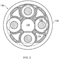
- FIG.3 A typical arrangement of the epicyclic gearbox is shown in Fig.3 .
- Each of the sun gear 128, planet gears 132 and ring gear 138 comprise teeth about their periphery to intermesh with the other gears. However, for clarity only exemplary portions of the teeth are illustrated in Fig.3 .
- Practical applications of a planetary epicyclic gearbox 130 generally comprise at least three planet gears 132.
- gearbox may drive additional and/or alternative components (e.g. the intermediate pressure compressor and/or a booster compressor, propeller (aero or hydro), or electrical generator). Additionally or alternatively such engines may have an alternative number of compressors and/or turbines and/or an alternative number of interconnecting shafts.
- the terms “axial” or “axially” refer to the principal and rotational axis 109, describing a dimension along a longitudinal axis of the gas turbine engine 10.
- the terms “radial” or “radially” refer to a dimension extending between the principal and rotational axis 109 and an outwardly displaced circumference therefrom.
- proximal refers to a direction towards the principal and rotational axis 109, or a component being relatively closer to the principal and rotational axis 109 as compared to a further component.
- distal refers to a direction towards the outwardly displaced circumference, or a component being relatively closer to the outwardly displaced circumference as compared to a further component.
- Directional references i.e., radial, axial, proximal, distal, upper, lower, upward, downward, left, right, lateral, front, back, top, bottom, above, below, vertical, horizontal, clockwise, counterclockwise, upstream, downstream, aft, etc.
- Connection references i.e., attached, coupled, connected, and joined
- Connection references are to be construed broadly and can include intermediate members and relative movement between elements unless otherwise stated.
- Connection references are, unless otherwise stated, not intended to infer that two elements are directly connected to, or in fixed relation to each other.
- the exemplary drawings are for purposes of illustration only and the dimensions, positions, order and relative sizes reflected in the drawings may vary.
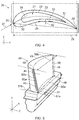
- Fig.4 illustrates a cross-sectional plan perspective of a known aerofoil 20.
- the known aerofoil 20 is a high pressure turbine blade forming part of the high pressure turbine 117 assembly.
- the aerofoil 20 comprises a cavity 21 defined by one or more internal surfaces 22.
- the aerofoil 20 comprises a suction surface 23 and a pressure surface 24.
- the suction surface 23, pressure surface 24, leading edge 25 and the trailing edge 26 extend between a root and a tip.
- the aerofoil 20 also comprises a camber line 31, which represents the mean camber extending between the leading edge 25 and the trailing edge 26.
- the external surface of the aerofoil 20, being that of one or more of the suction surface 23, pressure surface 24, and leading edge 25, is also shown to comprise a normal axis 32 extending in a direction perpendicular to a tangent 33 of the external surface.
- the normal direction 32 is shown, for example, to extend perpendicularly relative to the pressure surface 24, but may extend perpendicularly relative to any such further external surface.
- the aerofoil 20 comprises a leading edge 25, and a trailing edge 26 which is aft, or downstream, of leading edge 25.
- the leading edge is defined, in use, by a stagnation point, the stagnation point being a region of the aerofoil 20 when incident flow splits in order to flow over either the pressure surface or the suction surface of the aerofoil 20.
- the leading edge 25 is the portion of the aerofoil which first meets the gas flow 27.
- the leading edge 25 may represent a region of the external surface which is substantially perpendicular to the gas flow direction 27.
- the leading edge 25 may represent a region of the external surface which is immediately adjacent to the area substantially perpendicular to the gas flow direction 27.
- the trailing edge 26 may represent a region of the external surface where the pressure surface 24 meets the suction surface 23. In some examples, the trailing edge 26 may represent a region of the external surface, aft of the leading edge 25, where the fluid flow separated by the leading edge 25 rejoins. The trailing edge 26 is aft of the leading edge 25, so being spaced from the leading edge 25 in a chordwise direction 29. The distance between the leading edge 25 and the trailing edge 26 may be expressed as a chord length which extends along a chord line 30 between the leading edge 25 and the trailing edge 26. The chord length is the distance between the trailing edge 26 and the point on the leading edge 25 where the chord intersects the leading edge 25.
- the distance between the leading edge 25 and the trailing edge 26 may be expressed as a length which extends in a chordwise direction 29.
- the aerofoil 20 is shown to be at angled at a particular angle of attack 28, which extends parallel to the gas flow direction 27, and which may vary according to requirements. In some examples, the angle of attack may be measured relative to the chord line 30. In further examples, the angle of attack may be measured relative to the chordwise direction 29.
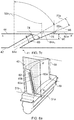
- Fig.5 shows an example of an aerofoil 40 comprising a cooling arrangement.
- the aerofoil 40 shown is a high pressure turbine blade, forming part of the high 17 pressure turbine assembly.
- the aerofoil 40 may be a turbine, vane, or compressor blade for use in a defined stage of the aforementioned sub-assemblies, or a further aerofoil for use in a gas turbine engine 10.
- the aerofoil 40 comprises a wall comprising an external surface.
- the wall may be any one of a suction surface 43, a pressure surface 44, a leading edge 45 and a trailing edge 46 spaced from the leading edge 45, in a chordwise direction 49 along a chord line 50.
- the aerofoil 40 comprises a cavity 41 defined by an internal surface 42.
- the cavity 41 is configured to receive a cooling fluid, in use.
- the suction surface 43, pressure surface 44, leading edge 45 and the trailing edge 46 extend between a root 57 and a tip 58.
- the tip 58 is spaced from the root 57 in a spanwise direction 59.
- the spanwise direction 59 extends from the root 57 towards the tip 58. In some examples, the spanwise direction 59 extends perpendicularly from the root 57 towards the tip 58.
- a first trench 60a and a second trench 60b are formed in the external surface, comprising a longitudinal length.
- the first trench 60a is formed in the pressure surface 44 of the aerofoil 40 at a first location 51a, measured along the chord line 50a relative to the leading edge 45.
- the second trench 60b is formed in the suction surface 43 of the aerofoil 40 at a second location 51b, measured along the chord line 50a relative to the leading edge 45.
- the chord length is traditionally measured over a chord line at a specific spanwise location, and can vary in length with radius.
- the chord length is defined as minimum distance from the leading edge to the trailing edge at a specified spanwise height. In Fig.5 , the chord length is measured over a chord line 50a at the root 57 of the aerofoil.
- chord length may be measured over a chord line 50b at the tip 58 of the aerofoil.
- the aerofoil 40 may comprise a number of further chord lines at various distances in the spanwise direction 59 measured relative to the root 57, on either or both of the suction surface 43 and the pressure surface 44.
- Such chord lines may include a chord line measured at, for example, the median location of the aerofoil 40.
- the chord lengths of the further chord lines may vary according to the degree of curvature and the particular shape of the respective aerofoil 40.
- the chordwise location of the first and second trenches 60a,60b may be expressed as a percentage value of the chord length.
- first and second trenches 60a,60b are shown to extend in the spanwise direction 59 at respective first and second chordwise locations 51a,51b.
- the respective first and second trenches 60a,60b may extend from and to particular percentages of the chord length over a range of spanwise distances measured relative to the root 57.
- the first and second trenches 60a,60b are separated by the leading edge 45, defined, in use, by the designed stagnation point.
- the respective first and second trenches 60a,60b extend between an area spaced from the root 57 and an area spaced from the tip 58.
- the trench 60 is orientated in a spanwise direction 59 and follows the curvature of the external surface within which it is formed.
- the trench 60 is of a constant depth over the longitudinal length of the trench 60.
- the trench 60 may be of variable depth over the longitudinal length of the trench 60.
- Fig.6a illustrates a cross-section of the aerofoil 40 shown in Fig.5 .
- Fig.6a shows the first trench 60a, and a first passageway 62a extending from a first passageway inlet 64a in the cavity 41, to a first passageway outlet 66a in the first trench 60a.
- Fig.6a also shows the second trench 60b, and a second passageway 62b extending from a second passageway inlet 64b in the cavity 41, to a second passageway outlet 66b in the second trench 60b.
- the first trench 60a and second trench 60b are formed in the leading edge region, i.e. the respective regions immediately adjacent the leading edge.
- the first trench 60a may be formed in the pressure surface 44, downstream of the leading edge 45.
- the second trench 60b may be formed in the suction surface 43 downstream of the leading edge 45.
- the wall of the aerofoil in the region surrounding the trenches is thickened, providing a thickened region 65.
- the thickened region 65 is shown adjacent the first trench 60a at the first location 51a, and the second trench 60b at the second location 51b.
- the thickened region 65 comprises a wall thickness which is greater than the wall thickness at a pressure or suction surface of the aerofoil.
- the aerofoil 40 may comprise a single thickened region 65 accommodating the first passageway 62a, first trench 60a, second passageway 62b, and second trench 60b.
- the aerofoil 40 may comprise may comprise two or more thickened regions, each located at a respective trench location 51a,51b.
- the first passageway 62a and the second passageway 62b intersect at an intersection point 67 within the wall of the aerofoil 40.
- the intersection point 67 is located in line with, and aft of the leading edge 45 per se.
- the first passageway 62a and the second passageway 62b are configured within the wall in the same plane, which is at an equivalent offset in the spanwise direction 59 from the root 57.
- the first passageway 62a and the second passageway 62b may be orientated towards the tip 58.
- the first passageway 62a and the second passageway 62b may be orientated towards the root 57.
- first passageway 62a and the second passageway 62b may be configured within the wall in dissimilar planes, relative to the spanwise direction 59.
- first passageway 62a may be orientated towards the tip 58
- second passageway 62b may be orientated towards the root 57, or vice-versa.
- first passageway 62a and the second passageway 62b are configured to intersect at the intersection point 67.
- the intersection point 67 may be in line with a camber line, or a gas flow direction.
- the intersection point may be adjacent to, or laterally displaced from the camber line, or the gas flow direction.
- first passageways 62a and a plurality of second passageways 62b there may be a plurality of intersection points 67 in each intersecting trench arrangement.
- Fig.6b shows an exploded view of the first trench 60a shown in Fig.5 .
- the first passageway 62a extends downstream from the intersection point 67 to a first passageway outlet 66a in the first trench 60a.
- the aerofoil 40 is shown to comprise a plurality of such first passageways 62a.
- the first passageways 62a are shown to be spaced in the spanwise direction 59 along the first trench 60a.
- the first trench 60a may comprise either a single or a plurality of first passageways 62a, according to requirements.
- Fig.6c shows an exploded view of the second trench 60b shown in Fig.5 and 6a .
- the second passageway 62b extends downstream from the intersection point 67 to a second pasageway outlet 66b in the second trench 60b.
- the aerofoil 40 is shown to comprise a plurality of such second passageways 62b.
- Each second passageway 62b is shown to be spaced in the spanwise direction 59 along the second trench 60b.
- the second trench 60b may comprise either a single or a plurality of second passageways 62b, according to requirements.
- Fig.6d shows an enlarged view of the first trench 60a, previously shown in Fig.6b . It will be appreciated that the features described herewith, in relation to Fig.6d , apply equally to the second passageway 62b, second trench 60b, second passageway inlet 64b, second passageway outlet 66b, and their respectively associated features, shown in Figs.6a and 6c , mutatis mutandis.
- Fig.6d shows the direction of flow of an incident working fluid 73, flowing over pressure surface 44 of the aerofoil 40 in a direction of flow.
- Fig.6d also shows a flow of cooling fluid 70, from the cavity 41, flowing along a first longitudinal passageway axis 72a before exiting the first passageway 62a into the first trench 60a.
- first and second sidewalls 74,76 merge to form an arcuate, or curvilinear profile.
- the first and second sidewalls 74,76 may be parallel or angled relative to one another.
- the second sidewall 76 is downstream of the first passageway outlet 66a, and laidback relative to the first passageway axis 72a.
- the first passageway axis 72a extends along the first passageway 62a from the first passageway inlet 64a, past the intersection point 67, and to the first passageway outlet 66a.
- Fig.6d also shows that, downstream of the intersection point 67, the first passageway 62a comprises both a first major axis 78a and a first minor axis 80a adjacent the intersection point 67, and both a second major axis 78b and a second minor axis 80b adjacent the first passageway outlet 66a.
- first major axis 78a and a first minor axis 80a immediately downstream of the intersection point 67 is equal to the first major axis 78a and a first minor axis 80a at the first passageway inlet 64a.
- the respective major axes 78a,78b represent the largest diameter across a cross-section of the respective passageways 62a,62b at a given position along the respective passageway axes 72a,72b.
- the major axes may be perpendicular to the longitudinal passageway axes 72a,72b.
- the largest diameter across the passageways 62a,62b are provided across the divergent profile at the location of the respective passageway outlets 66a,66b into the respective first and second trenches 60a,60b.
- the second major axis 78b may be indicative of the direction of divergence.
- the first major axis 78a represents a diameter across the respective passageways 62a,62b in a direction parallel to the second major axis 78b.
- the first major axis 78a represents a diameter across the respective passageways 62a,62b, prior to divergence.
- the first major axis 78a represents a diameter across the respective passageways 62a,62b at the respective passageway inlets 64a,64b.
- the major axes 78a,78b are shown to extend in a longitudinal direction relative to the first trench 60a.
- the major axes 78a,78b may extend in a spanwise direction.
- the major axes 78a,78b may extend in a chordwise direction.
- the respective minor axes 80a,80b represent the smallest diameter across a cross-section of the respective passageways 62a,62b at a given position along the respective passageway axes 72a,72b.
- the minor axis may be perpendicular to the longitudinal passageway axes 72a,72b.
- the smallest diameter across the passageways 62a,62b is perpendicular to the largest diameter across the divergent profile at the location of the respective passageway outlets 66a,66b into the respective first and second trenches 60a,60b.
- the second minor axis 80b may be perpendicular to either or both of the second major axis 78b, or the direction of divergence.
- the first minor axis 80a represents a diameter across the respective passageways 62a,62b, in a direction parallel to the second major axis 80b. According to examples, the first minor axis 80a represents a diameter across the respective passageways 62a,62b, prior to divergence. Additionally or alternatively, the first minor axis 80a represents a diameter across the respective passageways 62a,62b at the respective passageway inlets 64a,64b. In the example shown in Fig.6d , the minor axes 80a,80b are shown to extend in a transverse direction relative to the first trench 60a. In some examples, the minor axes 80a,80b may extend in a chordwise direction. In further examples, the minor axes 80a,80b may extend in a spanwise direction.
- first major axis 78a and second major axis 78b extend along a chordwise plane. In further examples, the first major axis 78a and second major axis 78b extend along different planes. In either example, either or both of the respective passageways 62a,62b and respective passageway axes 72a,72b may twist or vary. Such twisting may promote a vortical flow of cooling fluid flowing within either or both of the respective passageways 62a,62b. Referring again to Fig.6d , the second major axis 78b adjacent the respective passageway outlets 66a,66b, is greater than the first major axis 78a, shown downstream of the intersection point 67.
- the respective passageways 62a,62b diverge along the longitudinal passageway axes 72a,72b from the first major axis 78a towards the second major axis 78b.
- the respective passageways 62a,62b terminate in a divergent profile adjacent the respective passageway outlets 66a,66b.
- the divergent profile may diverge in at least two dimensions.
- the respective passageway outlets 66a,66b may have a cross-sectional shape of, for example, any one of an elongate slot, oval, regular polygon, irregular polygon, or any further shape according to requirements.
- the second minor axis 80b may be substantially equal to the first minor axis 80a.
- the first major axis 80a may equal the first minor axis 78a.
- the respective passageways 62a,62b may not diverge along the longitudinal passageway axes 72a,72b.
- the divergent profile may diverge in three dimensions.
- the first minor axis 78a may be greater than the second minor axis 78b.
- Figs.7a-7c show projections of the aerofoil 40 shown in Fig.5 .
- Fig.7a shows a cross section through both the aerofoil 40 and the first trench 60a between points A-A'.
- Cross-section A-A' provides a chordwise cross-section of the aerofoil 40 taken at the midpoint of the span.
- Fig.7b shows a cross-sectional perspective of the aerofoil 40 and an example of the first trench 60a, of the type described in Figs.5-6d , between points A-A'.
- Figs.7b and 7c show the first passageway 62a extending along the first longitudinal passageway axis 72a, to the first passageway outlet 66a in the first trench 60.
- Normal axes 52a 1 ,52a 2 (not shown) extend perpendicularly relative to the external surface at a first and second location 51a,51b.
- the first passageway axis 72a is shown to be canted, at a first angle 84a 1 , from the normal axis 52a 1 , which extends in a direction perpendicular to a first chordwise tangent 82a of the external surface, so that the first passageway axis 72a is directed downstream, in a chordwise direction.
- the first chordwise tangent 82a at the first location 51a intersects the first passageway axis 72a at the first angle 84a 1 , which provides the first passageway 62a with a downstream trajectory relative to the normal axis 52a 1 .
- the first angle 84a 1 ,84a 2 (not shown) defines an angle between the respective first and second passageway axes 72a,72b, and a portion of respective first chordwise tangent 82a of the external surface, at the first and second locations 51 a,51 b.
- the first angle 84a 1 ,84a 2 is ordinarily taken to be an interior angle at the intersection between the respective longitudinal axes 72a,72b of the first and second passageways 62a,62b, and the respective first chordwise tangent 82a.
- the first angle 84a 1 ,84a 2 ordinarily extends downstream of, and between the respective longitudinal axes 72a,72b and respective first chordwise tangents 82a.
- the first angle 84a 1 ,84a 2 is at least 90 degrees.
- the first angle 84a 1 ,84a 2 provides the respective passageway axes 72a,72b with a downstream trajectory relative to the respective normal axes 52a 1 ,52a 2 .
- the first angle 84a 1 ,84a 2 is a first chordwise angle. It will be appreciated that further constructions of the first angle 84a 1 ,84a 2 are possible and within the scope of the current disclosure.
- the first trench 60a is shown to comprise a first sidewall 74, a second sidewall 76, and a trench bottom surface 75.
- trench 60 may contain one or more first sidewalls 74, one or more second sidewalls 76, and optionally one or more bottom surfaces 75.
- the bottom of the trench describes a location of the trench having the greatest depth relative to the external surface at the first location 51a.
- the bottom surface 75 may be a planar section of constant depth.
- the bottom surface 75 may be a planar section of varying depth.
- the bottom surface 75 may be a non-planar section of varying depth relative to the external surface at the first location 51a.
- the bottom of the trench 60 may comprise a linear surface.
- the bottom of the trench 60 may not comprise a bottom surface, i.e., the first sidewall 74 may abut, or merge, into the second sidewall 76.
- the first trench 60a comprises a trench depth 91 which is equal to or less than the second major axis 78b.
- the trench depth 91 represents a distance between the tangent of the external surface at the first location 51a, and a parallel tangent of the bottom of the trench 60.
- the trench depth 91 may be equal to or less than the second major axis 78b.
- the trench depth 91 may be equal to or less than the first major axis 78a.
- the first trench 60a further comprises a trench width 93 which is equal to or greater than the second major axis 78b.
- the trench width 93 represents a distance between the first sidewall 74 and the second sidewall 76.
- the trench width 93 may be equal to or greater than the second major axis 78b, or alternatively, equal to or greater than the first major axis 78a.
- the first passageway axis 72a of the first trench 60a is angled, relative to the first chordwise tangent 82a at the first location 51a, at a greater angle than in the example of Fig.7b .
- the first passageway axis 72a is increasingly angled in the chordwise direction 49 (i.e. towards the trailing edge 46) relative to the trench shown in Fig.7b .
- the first angle 84a 1 ,84a 2 may vary according to, for example, one or more of the spanwise or chordwise position of the first trench 60a, the position of the first passageway 62a in the first trench 60a, or cooling requirements, according to predetermined conditions.
- the second sidewall 76 is laidback from the first longitudinal passageway axis 72 at an increased second angle 88a 1 relative to the first chordwise tangent 82a.
- the second angle 88a 1 , 88a 2 (not shown) defines an angle between the tangent 86 of the respective second sidewalls 76, and a portion of the first chordwise tangent 82a of the external surfaces at the respective first and second locations 51 a,51 b.
- the second angle 88a 1 ,88a 2 is ordinarily taken to be an interior angle at the intersection between respective tangents of the respective laidback second sidewalls 76, and the respective tangents 82a,82b of the external surface.
- the second angles 88a 1 ,88a 2 ordinarily extend downstream of, and between the respective tangents of the respective second sidewalls 76, and the tangents 82a,82b of the external surface.
- the respective second sidewalls 76 are both downstream of the passageway outlets 66a,66b, and at a second angle 88a 1 ,88a 2 relative to the respective first chordwise tangents 82a,82b, which are greater than the first angle 84a 1 ,84a 2 .
- the second angle 88a 1 ,88a 2 provides the respective second sidewalls 76 with an increased downstream trajectory relative to both the first chordwise tangent 82a,82b and the first and second passageway axes 72a,72b.
- the second angle may be an open angle. By an open angle, it is meant that the second angle is at least 90 degrees.
- Fig.8a-c show projections of the aerofoil 40 previously shown in Figs.5 and 7a-7c .
- Fig.8a shows a cross section through both the aerofoil 40 and the first trench 60a between points B-B'.
- Cross-section B-B' provides a spanwise cross-section B-B' of the aerofoil 40 at the first position 51a.
- Fig.8b shows a cross-sectional perspective of the aerofoil 40 and an example of the first trench 60a, of the type described in Figs.5a-7c , between points B-B'.
- Figs.8b and 8c show the first passageway 62a extending along the first longitudinal passageway axis 72a to the first passageway outlet 66a in the first trench 60a.
- Normal axes 52b 1 ,52b 2 (not shown) extend perpendicularly relative to the external surface 44 at the first and second locations 51a,51 b.
- the first passageway axis 72a is shown to be canted, at a first spanwise angle 84b 1 , from the normal axis 52b 1 , which extends in a direction perpendicular to a first spanwise tangent 83a of the external surface, such that the first passageway axis 72a is directed towards the tip 58.
- the first passageway axis 72a is directed towards the root 57.
- the first spanwise tangent 83a at the first location 51a intersects the first passageway axis 72a at the first spanwise angle 84b 1 , which provides the first passageway 62a with a spanwise trajectory relative to the normal axis 52b 1 .
- the first passageway axis 72a of the first trench 60a is angled, relative to the first spanwise tangent 83a at the first location 51a, at a greater angle than in the example of Fig.8b .
- the first passageway axis 72a is increasingly angled in the spanwise direction 59 (i.e. towards the tip 58), relative to the trench shown in Fig.8b .
- the first spanwise angle 84b 1 may vary according to, for example, one or more of the spanwise or chordwise position of the first trench 60a, the position of the first passageway 62a in the first trench 60a, or cooling requirements, according to predetermined conditions.
- the first spanwise angle 84b 1 ,84b 2 (not shown) defines an angle between the respective first and second passageway axes 72a,72b, and a portion of respective first and second spanwise tangents 83a,83b of the external surface, at the first and second location 51a,51 b.
- the first spanwise angle 84b 1 , 84b 2 is ordinarily taken to be an interior angle at the intersection between the respective longitudinal axes of the first and second passageways 72a,72b, and the respective spanwise tangents 83a,83b.
- the first spanwise angle 84b 1 ,84b 2 ordinarily extends downstream of, and between the respective longitudinal axes 72a,72b and spanwise tangents 83a,83b.
- the first angle 84a 1 , 84a 2 is at least 90 degrees.
- the first angle 84a 1 , 84a 2 provides the respective passageway axes 72a,72b with a spanwise trajectory relative to the respective normal axes 51a,51 b.
- the first spanwise angle 84b 1 , 84b 2 is a first spanwise angle. It will be appreciated that further constructions of the first spanwise angle 84b 1 ,84b 2 are possible and within the scope of the current disclosure.
- the second sidewall 76 is laidback from the longitudinal passageway axis 72 at an increased second spanwise angle 88b 1 relative to the second spanwise tangent 83.
- the second spanwise angle 88b 1 , 88b 2 (not shown) defines an angle between the tangent of the respective second sidewalls 76, and a portion of the respective second spanwise tangents 83 of the external surfaces at the respective first and second locations 51a,51 b.
- the second spanwise angle 88b 1 ,88b 2 is ordinarily taken to be an interior angle at the intersection between respective tangents of the respective second sidewalls 76, and the respective tangents 83 of the external surface.
- the second spanwise angles 88b 1 ,88b 2 ordinarily extend spanwise of, and between the respective tangents of the second sidewalls, and the second spanwise tangents 83.
- the respective second sidewalls 76 are downstream of, and displaced in the spanwise direction from the passageway outlets 66a,66b, at second angles 88a 1 ,88a 2 relative to the second spanwise tangents 83, which are greater than the first angles 84a 1 ,84a 2 .
- the second spanwise angle 88b 1 ,88b 2 provides the respective second sidewall 76 with an increased downstream trajectory relative to both the spanwise tangent 83 and the first and second passageway axes 72a,72b.
- the second spanwise angle may be an open angle. By an open angle, it is meant that the second angle is at least 90 degrees.
- the trench arrangements described in Figs.5-8c may be located at further chordwise locations on the surface of the aerofoil 40.
- the first trench 60a, the second trench 60b, and the respective passageways 62a,62b may be located on the pressure surface 44.
- the first trench 60a and the second trench, and the respective passageways 62a,62b, 60b may be located on the suction surface 43.
- the first trench 60a and the second trench 60b may not be separated by the stagnation point, or adjacent the leading edge 45.
- the remaining features described in relation to Figs.5-8c may be employed separately or in combination with the features relating to the presently described example.
- two or more trenches 60a,60b are provided within an aerofoil 40.
- the aerofoil is suitable for use in a gas turbine engine 10.
- the aerofoil 40 may be a turbine blade.
- the aerofoil 40 may be a vane.
- the aerofoil 40 may be a cast article.
- the aerofoil 40 may be an investment cast article.
- the aerofoil 40 may be of single-piece construction.
- the aerofoil 40 may be a unitary body and the respective trenches 60a,60b may be formed into a surface of the unitary body.
- One or more of respective passageways 62a,62b, divergent profiles, or trenches 60a,60b may be formed in the aerofoil 40 via a mechanical machining process.
- one or more of respective passageways 62a,62b, divergent profiles, or trenches 60a,60b may be formed in the aerofoil 40 via a non-traditional machining process.
- the non-traditional machining process may be one or more of a chemical machining process, an electro-discharge machining process, a laser-based machining process, or an electron beam machining process.
- one or more of respective passageways 62a,62b, divergent profiles, or trenches 60a,60b may be formed in the aerofoil 40 during manufacture of the aerofoil 40.
- the aerofoil 40 may be constructed by an additive manufacturing method such as, for example, 3-D printing, direct laser deposition, or selective laser sintering.
- any further machining or manufacturing process capable of repeatable, high-accuracy material addition or removal may be employed in either or both of the machining or manufacture of each respective trench 60a,60b or respective passageway 62a,62b.
- the cooling fluid is air. In some examples, the cooling fluid is an air mixture. In some examples, the cooling fluid may comprise a liquid. In further examples, the aerofoil 40 may comprise nickel. The aerofoil 40 may be a nickel alloy. The aerofoil 40 may be a nickel-based superalloy. The aerofoil 40 may be a cobalt-based superalloy. The aerofoil 40 may be an iron-based superalloy. In further examples, the aerofoil 40 may comprise titanium. The aerofoil 40 may be a titanium alloy. The aerofoil 40 may be a titanium-alumnide. The aerofoil 40 may be a ceramic matrix composite. The aerofoil 40 may be a metal matrix composite.
Landscapes
- Engineering & Computer Science (AREA)
- Mechanical Engineering (AREA)
- General Engineering & Computer Science (AREA)
- Turbine Rotor Nozzle Sealing (AREA)
Abstract
Description
- The present disclosure relates to an aerofoil. In particular, the present disclosure relates to an aerofoil comprising an aerofoil cooling arrangement, for use in a gas turbine engine.
- In the field of gas turbine engines, there is a drive for enhanced efficiency and performance. It is common to introduce steps to increase internal combustion temperatures, due to combustion being increasingly efficient at higher temperatures. However, safe operating temperatures of materials used in the hottest regions, such as the combustor and the turbine sections, place temperature constraints on uppermost operating temperatures. Thus, blades are commonly cooled to allow operation in environments above yield or melting temperatures of their constituent materials, whilst ensuring blade metal temperatures themselves remain below such temperature limits. In particular, high pressure turbine blades are commonly cooled using cooling air, bled from the compressor, that is significantly cooler then the main stream gas flow. Typically this air is used, in internal passages, to convectively cool the body of the blade, before being ejected on to the aerofoil surface to form a film of cool air. Such films prevent the hot main stream gas flow from overheating the aerofoil surface. To improve film cooling performance, particularly in the presences of a pressure gradient, it is known to shape, and orientate cooling holes in a particularly advantageous cooling direction.
- With developing cooling hole technology, there are issues which limit the effectiveness of cooling holes in environments containing high levels of inorganic debris, which subsequently enters the main gas flow. Such environments may include, for example, a sandy- or desert-like region, or a volcanically active region, where inorganic material may be retained within the local atmosphere. In particular, shaped hole exits are prone to either restriction or blockage due to the build-up of main stream gas debris on the aerofoil surface and cooling hole exit. This reduces film performance and component life due to ineffective cooling of the turbine blade. This problem may be exacerbated by coatings, such as Thermal Barrier Coating (TBC), congregating around or within the hole during manufacture. This may reduce coolant flow rate, or a separate the film, further reducing film cooling effectiveness.
- To provide restriction or blockage resistance, it is known to provide a cooling trench in a surface of the turbine blade. Thus, the cooling holes exit into the trench, so that main stream gas debris washes over the trench without interacting with the cooling hole exits. However, the application of such trenches results in the need for local wall thickening to incorporate cooling holes into the blade. This may create a local temperature increase within the thickened region for a given configuration of cooling holes, which may limit component life due to ineffective cooling. Thus, it is an object of the invention to provide an aerofoil comprising a cooling arrangement which provides either or both of a reduced susceptibility to blockage and improved cooling.
- According to a first aspect there is provided an aerofoil, the aerofoil comprising a wall comprising an external surface, and an internal surface defining a cavity for receiving a cooling fluid in use. The aerofoil further comprises a first trench formed in the external surface, and a second trench formed in the external surface; a first passageway extending from a first passageway inlet in the cavity to a first passageway outlet in the first trench, and a second passageway extending from a second passageway inlet in the cavity to a second passageway outlet in the second trench. The first passageway and second passageway intersect within the wall.
- The arrangement may allow respective passageways to break out into the bottom of a trench rather than the surface of the aerofoil. This may also allow the first passageway to be provided at a first angle, and the second passageway to be provided at a second angle. Such angling of the respective first and second passageways may provide the respective passageways with a downstream trajectory of a cooling fluid. Such a downstream trajectory may allow the flow vectors of the cooling fluid to at least partially match the flow vectors of the gas stream. This may aid in minimising losses and provide additional stabilisation of the resultant cooling film. Thus, the cooling film may be additionally stable and effective. Additionally, the arrangement may provide improved tolerance to either or both of restriction and blockage of the respective passageways due to debris accumulating in, or adjacent to, the respective passageway outlets. This may be achieved through the specific orientation of either or both of the passageways and configuration of the trench.
- In conjunction with the first and second trenches, the configuration of the first and second passageways may provide additional internal surface area within the passageways over which to transfer heat between the walls of the respective passageways and the cooling fluid. The first passageway and second passageway intersect at an intersection point within the wall. The intersection point may be located between the first passageway inlet and the first passageway outlet, and between the second passageway inlet and second first passageway outlet. Through intersection of the first and second passageways, the arrangement may provide additional turbulation, in use, of the cooling fluid downstream of the intersection point. Such additional turbulation may provide the effect of resetting the thermal boundary layer within the respective first and second passageways at the point of intersection. Such resetting may provide an additional cooling effect by removing stagnant or slow moving flow close to the wall, so providing an increased thermal gradient in this location. This may drive higher heat transfer following the point of intersection. Such intersection of the cooling passageways may also provide additional turbulation of cooling fluid flowing into the first and second trenches if the length of the passageway following the intersection is not sufficient to fully re-establish the boundary layer. Such turbulation may also cause an increase in thermal gradient at the passageway outlet in a similar manner to that described above. By providing the first and second passageway with additional surface area for a given wall thickness and a means to restart the thermal boundary layer, the cooling effect may be improved without altering respective flow rates of cooling fluid flowing through the respective passages.
- The first trench may be formed in the external surface at a first trench location. The second trench may be formed in the external surface at a second trench location. Thus, the first trench location and the second trench location may be located either side of a stagnation point. The stagnation point may be the leading edge of the aerofoil. The first trench may be configured to provide a cooling film over a first gas washed surface. The second trench may be configured to provide a cooling film over a second gas washed surface, which is distinct from the second gas washed surface. The first gas washed surface may be separated from the second gas washed surface by one or more of the stagnation point, stagnation point region, leading edge, or leading edge region. The leading edge may be cooled by conductive heat transfer between walls of the internal cavity or the respective passageways and the cooling fluid. In some examples, the first and second trenches may comprise either or both of two or more first, and two or more second passageways. Each of the respective first and second passageways may be spaced in the spanwise direction. In some examples, each of the first and second passageways spaced in the spanwise direction may form discrete pairs of passageways. The spanwise spacing between each pair may be equal. The spanwise spacing between each pair may be disparate.
- The first trench location and the second trench location may be located adjacent the stagnation point. Thus, the portion of the aerofoil cooled by conductive heat transfer between walls of the respective passageways and the cooling fluid may be minimised. The external surface area of the aerofoil cooled by heat transfer between the external surface and the cooling film may be maximised. In locating the first and second trench adjacent the leading edge, the respective first and second trench locations may be located either side of, and adjacent to, an intended stagnation point. Thus, the first and second trench location may extend in a spanwise direction. The first and second trench location may be located at a respective first and second chordwise location in the external surface.
- The wall may comprise a thickened region, adjacent the first and second location, comprising a wall thickness which is greater than the wall thickness at a pressure or suction surface of the aerofoil. Thus, the single thickened region may comprise the first trench location and the second trench location. Furthermore, the single thickened region may comprise the first passageway and second passageway. In further examples, a first and second thickened region of the respective first and second locations may be distinct. Thus, each thickened region may comprise a first trench location or a second trench location.
- The first passageway may comprise a first longitudinal axis. The second passageway may comprise a second longitudinal axis. The first and second longitudinal axes may extend over a substantial portion of the respective first and second passageways. The first and second passageway may be substantially straight over an entire axial length of the passageways. Thus, first and second longitudinal axes may extend through both the passageway inlets in the cavity and the passageway outlets in the trench. Alternatively, the passageways may comprise one or more curved or angled portions, wherein the longitudinal axes extends over only a portion of the passageways, and through the passageway outlets only. Thus, the first and second passageways may be at least substantially straight. Alternatively, the first and second passageways may be at least substantially curved.
- The first longitudinal axis and the second longitudinal axis may define a dihedral angle. The dihedral angle may be the internal angle between the first longitudinal axis and the second longitudinal axis, downstream of the intersection point, the dihedral angle may be between about 5 to about 170 degrees. The dihedral angle may be between about 10 to about 140 degrees. The dihedral angle may be between about 15 to about 110 degrees. The dihedral angle may be between about 20 to about 90 degrees. The dihedral angle may be between about 25 to about 70 degrees.
- The first longitudinal axis and the second longitudinal axis may extend in a chordwise direction. The first longitudinal axis and the second longitudinal axis may be located at a first and second spanwise location in the external surface. The first longitudinal axis and the second longitudinal axis may extend in a chordwise direction at or from the respective first and second spanwise locations. The first longitudinal axis and the second longitudinal axis may extend along a single plane. The plane may be a chordwise plane substantially perpendicular to the spanwise direction of the first trench and the second trench.
- The first longitudinal axis may intersect a first tangent of the external surface at the first location at a first angle. The second longitudinal axis may intersect a second tangent of the external surface at the second location at a first angle. Thus, the respective first angles provide the first passageway with a downstream trajectory relative to the first tangent, and the second passageway with a downstream trajectory relative to the second tangent. In some examples, the respective first angles may be equal. In further examples, the respective first angles may be disparate. The first angle may define an angle between the respective first and second longitudinal axes of the first and second passageways, and a portion of the respective first and second tangents at the first and second locations. The first angle may be an interior angle at the intersection between the respective longitudinal axes of the first and second passageways, and the respective tangents of the external surface. Thus, the first angles may extend downstream of, and between the respective longitudinal axes and the tangents of the external surface. The first angle may be an open angle, i.e. where the first angle is at least 90 degrees. In some examples, the first angles may be between about 90 and about 165 degrees. The first angles may be between about 93 and about 150 degrees. The first angles may be between about 95 and about 140 degrees.
- The first and second trenches may comprise respective laidback second sidewalls downstream of the respective passageway outlets. Thus, the term laidback means that the respective second sidewalls are at a greater angle, relative to the respective tangents, than the respective longitudinal axes. The laidback second sidewalls may reduce either or both of mixing losses and turbulent flow downstream of the respective trenches, by expanding or diffusing the flow before it enters the gas stream. Thus, the laidback sidewalls may provide improved mixing of the cooling fluid with the main stream fluid flow. Improved flow, or mixing, of the cooling fluid on the surface of the aerofoil, via the laidback sidewalls, may provide both an increasingly stable and effective cooling film. Thus, the arrangement may provide a reduction in the amount of cooling fluid used, and hence improved component efficiency, and increased component life. Such improvements may result in enhanced engine performance, reduced operating costs, and increased efficiency.
- A tangent of the second sidewall of the first trench may intersect the first tangent of the external surface at the first location at a second angle. A tangent of the second sidewall of the second trench may intersect the second tangent of the external surface at the second location at a second angle. Thus, the respective second sidewalls provide the second sidewalls with a downstream trajectory relative to the respective first and second tangents. The respective second angles may greater than the respective first angles, relative to the respective first and second tangents. The second angles may define an angle between the tangents of the respective second sidewalls, and a portion of the respective tangents of the external surface at the first and second locations. The second angles may be an interior angle at the intersection between respective tangents of the respective second sidewalls, and the respective tangents of the external surface. Thus, the second angles may extend downstream of, and between the respective tangents of the second sidewalls, and the tangents of the external surface. The second angle may be an open angle, i.e. where the second angle is at least 90 degrees. In some examples, the second angles may be between about 90 and about 175 degrees. The second angles may be between about 94 and about 160 degrees. The second angles may be between about 96 and about 150 degrees.
- In further examples, the first angles and second angles may be measured relative any one or more of a different reference plane, tangent, axis or feature. However, in all examples, the second angles provide the laidback sidewall with an increasingly downstream trajectory relative to the respective first angles. In some examples, the second angles may be greater than the first angles by between about 0 and about 60 degrees. In some examples, the second angles may be greater than the first angles by between about 0.5 and about 60 degrees. In some examples, the second angles may be greater than the first angles by between about 1 and about 40 degrees [narrow]. The second angles may be greater than the first angles by between about 5 and about 20 degrees. The laidback sidewalls may be aft of the passageway exits. Furthermore, at least a portion of the laidback sidewalls may be aft of the respective longitudinal axes of the respective passageways.
- The first and second passageways may comprise both a first major axis and a first minor axis adjacent the respective passageway inlets, and both a second major axis and a second minor axis adjacent the respective passageway outlets. The second major axes adjacent the respective passageway outlets may be greater than the first major axes adjacent the respective passageway inlets. The respective passageways may terminate in a divergent profile adjacent the respective passageway outlets. Each of the first minor axis, second major axis, first major axis and second minor axis may comprise a respective length. Thus, the respective first and second passageways may diverge, or increase from a first major axis either or both of adjacent the respective passageway inlets and downstream of the intersection point, to a second major axis adjacent the respective passageway outlets. The divergence may occur over the entire length of the first and second passageways. Alternatively, the divergence may occur over only a portion of the first and second passageways. Thus, the first and second passageways may diverge immediately adjacent the respective passageway outlets. Thus, the reduced velocity of the cooling fluid may act to provide enhanced film cooling onto the external surface of the aerofoil. In some examples, the first major axes may be between about 0.1mm and about 3mm. The first major axes may be between about 0.2mm and about 2mm. The first major axes may be between about 0.2mm and about 1mm. In some examples, the second major axes may be between about 0.1mm and about 3mm. The second major axes may be between about 0.2mm and about 2mm. The second major axes may be between about 0.2mm and about 1 mm.
- Additionally or alternatively, the respective passageways may diverge, or increase from a first minor axis either or both of adjacent the respective passageway inlets and downstream of the intersection point, to a second minor axis adjacent the respective passageway outlets. The second minor axes may be greater than the first minor axes. Such divergence may occur over the entire length of the passageways. Alternatively, the passageways may not diverge, or increase from the first minor axis. The respective second minor axes may be equal to the respective first minor axes. In some examples, the first minor axes may be between about 0.1mm and about 3mm. The first minor axes may be between about 0.2mm and about 2mm. The first minor axes may be between about 0.2mm and about 1mm. In some examples, the second minor axes may be between about 0.1mm and about 3mm. The second minor axes may be between about 0.2mm and about 2mm. The second minor axes may be between about 0.2mm and about 1mm.
- The passageways may terminate in a two dimensional divergent profile adjacent the respective passageway outlets. The two dimensional divergent profiles may diverge along the first and second longitudinal axes. Thus, the passageways may diverge along the first and second longitudinal axes in a further dimension. The further dimension may be the x axis. The further dimension may be the y axis. The further dimension may be the z axis. In some examples, the second major axis of the passageway outlets may be greater than the first major axes of the passageway inlets. Thus, the respective second minor axes of the passageway outlets may be approximately equal to the respective first minor axes of the passageway inlets. Alternatively, the respective second minor axes of the passageway outlets may be greater than the respective first minor axes of the passageway inlets. Thus, the respective second major axes of the passageway outlets may be approximately equal to the respective first major axes of the passageway inlets. The respective second minor axes of the passageway outlets may be less than the respective first minor axes of the passageway inlets. Alternatively, the respective second major axes of the passageway outlets may be less than the respective first major axes of the passageway inlets. The two dimensional divergent profiles may be in the form of a fan. The two dimensional divergent profiles may be in the form of a slot. The cross-sectional profiles may be perpendicular to the respective longitudinal axes.
- The passageways may terminate in a three dimensional divergent profile adjacent the first and second passageway outlets. The three dimensional divergent profiles may diverge along the respective first and second longitudinal axes. Thus, the passageways may diverge along the respective longitudinal axes in two or more further dimensions. The two further dimensions may be two or more of the x, y and z axes. In this way, the respective second major axes of the passageway outlets may be greater than the respective first major axes of the passageway inlets. The respective second minor axes of the passageways outlets may be greater than the respective first minor axes of the passageway inlets. The three dimensional divergent profiles may be in the form of a cone. The three dimensional divergent profiles may be in the form of a fan. The cross-sectional profiles may be perpendicular to the respective longitudinal axes.
- The passageway outlets may terminate in the cross-sectional profile of an ellipse. In further examples, the passageway outlets may terminate in the cross-sectional profile of a circle. In further examples, the passageway outlets may terminate in the cross-sectional profile of a slot. In further examples, the passageway outlets may terminate in the cross-sectional profile of a regular polygon. The passageway outlets may terminate in the cross-sectional profile of an irregular polygon. The passageway outlets may terminate in the cross-sectional profile of a rectangle. The passageway outlets may terminate in the cross-sectional profile of an oval. The oval may comprise two parallel sides.
- The first and second trenches may comprise a trench depth which may be equal to or less than the respective second major axes. The respective trench depths may be equal to or less than the respective first major axes. The trench depths may be between about 0.1 and about 3 times the respective first major axes. The trench depths may be between about 0.3 and about 2 times respective first major axes. The trench depths may be between about 0.5 and about 1.5 times the respective first major axes. The respective trench depths may represent a distance between the first tangent of the external surface at the respective first or second locations, and parallel tangents of the bottom of the first and second respective trenches. Thus, the bottom of the trenches may represent the deepest point within the respective trenches, relative to the external surface. The bottom of the trench may be a single location within a curved bottom surface, or may be a planar portion as part of a bottom wall.
- One or more of the respective first side walls and the respective second side walls may comprise a planar portion. Thus, one or more of the first side wall, and the second side wall may comprise a least a portion which is linear, or flat. Additionally or alternatively, one or more of the respective first side walls, and the respective second side walls may comprise a curved portion. Thus, one or more of the first side wall, and the second side may be curvilinear, or curved. Thus, the respective first side wall and second side walls may merge to form an arcuate profile. Trenches may comprise three or more sides. Thus, one or more of the first trench and the second trench may comprise three or more faces within the trench. One or more of the faces may be the planar portion as part of the bottom wall. According to further examples, the trench may further comprise two or more bottom walls. Thus, in further examples, one or more of the first side wall, second side wall, and bottom wall may merge to form an arcuate profile. Additionally or alternatively, respective trenches may comprise two or more sides. Thus, one or more of the first trench and the second trench may comprise two or more distinct faces within the trench.
- The first and second trenches may comprise a trench width which is equal to or greater than the respective second major axes. The first and second trenches may comprise a trench width which is equal to or greater than the respective first major axes. The trench width may be between about 0.3 and about 3 times the first major axis. The trench width may be between about 0.5 and about 2 times the first major axis. The trench width may be between about 0.8 and about 1.5 times the first major axis.
- According to a second aspect, there is provided a gas turbine engine comprising, except where mutually exclusive, an aerofoil comprising any one or more features previously described. According to a third aspect, there is provided a geared turbo fan comprising, except where mutually exclusive, an aerofoil comprising any one or more features previously described. In some examples, the aerofoil may be a turbine blade. In further examples, the aerofoil may be a vane.
- The skilled person will appreciate that except where mutually exclusive, a feature described in relation to any one of the above aspects may be applied mutatis mutandis to any other aspect. Furthermore except where mutually exclusive any feature described herein may be applied to any aspect and/or combined with any other feature described herein.
- Embodiments will now be described by way of example only, with reference to the Figures, in which:
-
Fig.1 is a sectional side view of a gas turbine engine; -
Fig.2 is an expanded sectional view of a gearbox and compression section; -
Fig.3 is a sectional frontal view of the gearbox; -
Fig.4 is a plan view of an aerofoil known within the art; -
Fig.5 is a plan perspective view of an aerofoil comprising a cooling arrangement; -
Fig.6a is a wire frame perspective of the cooling hole arrangement ofFig.5 ; -
Fig.6b is a wire frame perspective of the cooling hole arrangement ofFig.6a ; -
Fig.6c is a wire frame perspective of the cooling hole arrangement ofFig.6a ; -
Fig.6d is an exploded perspective of the cooling hole arrangement shown inFig.6a ; -
Fig.7a is a perspective view of the aerofoil ofFig.5 , along with section A-A'; -
Fig.7b is a first sectional view of section A-A'; -
Fig.7c is a second sectional view of section A-A'; -
Fig.8a is a perspective view of the aerofoil ofFig.5 , along with section B-B"; -
Fig.8b is a first sectional view of section B-B"; and, -
Fig.8c is a second sectional view of section B-B", according to examples of the present disclosure. -
Fig.1 illustrates a gas turbine engine 110 having a principalrotational axis 109. Theengine 10 comprises anair intake 112 and apropulsive fan 123 that generates two airflows A and B. The gas turbine engine 100 comprises acore engine 111 having, in axial flow A, a low pressure compressor 14, a high-pressure compressor 115,combustion equipment 116, a high-pressure turbine 117, alow pressure turbine 119 and acore exhaust nozzle 120. Anacelle 121 surrounds the gas turbine engine 110 and defines, in axial flow B, abypass duct 122 and abypass exhaust nozzle 118. Thefan 123 is attached to and driven by thelow pressure turbine 119 viashaft 126 andepicyclic gearbox 130. - The gas turbine engine 110 works in a conventional manner with air in the core airflow A being accelerated and compressed by the low pressure compressor 14 and directed into the
high pressure compressor 115 where further compression takes place. The compressed air exhausted from thehigh pressure compressor 115 is directed into thecombustion equipment 116 where it is mixed with fuel and the mixture is combusted. The resultant hot combustion products then expand through, and thereby drive the high pressure andlow pressure turbines nozzle 120 to provide some propulsive thrust. Thehigh pressure turbine 117 drives thehigh pressure compressor 115 by a suitable interconnecting shaft. Thefan 123 generally provides the majority of the propulsive thrust. Theepicyclic gearbox 130 is a reduction gearbox. - A known mechanical arrangement for a geared fan gas turbine engine 110 is shown in
Fig.2 . Thelow pressure turbine 119 drives theshaft 126, which is coupled to a sun wheel, or sun gear, 128 of theepicyclic gear arrangement 130. Radially outwardly of thesun gear 128 and intermeshing therewith, in a conventional manner, is a plurality of planet gears 132 that are coupled together by aplanet carrier 134. The planet carrier134 constrains the planet gears 132 to precess around thesun gear 128 in synchronicity whilst enabling eachplanet gear 132 to rotate about its own axis. Theplanet carrier 134 is coupled vialinkages 136 to thefan 123 in order to drive its rotation about the engine axis 19. Radially outwardly of the planet gears 132 and intermeshing therewith is an annulus orring gear 138 that is coupled, vialinkages 140, to astationary supporting structure 124. - The
epicyclic gearbox 130 is of the planetary type, in that theplanet carrier 134 rotates about thesun gear 128 and is coupled to an output shaft vialinkages 136. In other applications thegearbox 130 may be a differential gearbox in which thering gear 138 also rotates in the opposite sense and is coupled to a different output shaft vialinkages 140. Anepicyclic gearbox 130 must be lubricated, by oil or another fluid. However, the oil becomes heated by being worked during operation of theepicyclic gearbox 130. Furthermore, the oil may accumulate particulate debris from the components of theepicyclic gearbox 130 which may cause seizing or other problems. It is therefore necessary to eject the oil efficiently from theepicyclic gearbox 130 to allow its replacement by spraying in fresh, cool oil. Ejection of the oil, particularly when it is collected for cleaning before being returned to the reservoir from which fresh oil is supplied, is referred to as oil scavenge. - A typical arrangement of the epicyclic gearbox is shown in
Fig.3 . Each of thesun gear 128, planet gears 132 andring gear 138 comprise teeth about their periphery to intermesh with the other gears. However, for clarity only exemplary portions of the teeth are illustrated inFig.3 . There are fourplanet gears 132 illustrated, although it will be apparent to the skilled reader that more or fewer planet gears 132 may be provided within the scope of the claimed invention. Practical applications of a planetaryepicyclic gearbox 130 generally comprise at least three planet gears 132. - Additionally or alternatively the gearbox may drive additional and/or alternative components (e.g. the intermediate pressure compressor and/or a booster compressor, propeller (aero or hydro), or electrical generator). Additionally or alternatively such engines may have an alternative number of compressors and/or turbines and/or an alternative number of interconnecting shafts.
- Unless otherwise stated, the terms "axial" or "axially" refer to the principal and
rotational axis 109, describing a dimension along a longitudinal axis of thegas turbine engine 10. The terms "aft" or "downstream", unless otherwise stated, refers to a direction towards either or both of the rear and outlet of thegas turbine engine 10 relative to the principal androtational axis 109. The terms "forward" or "upstream", unless otherwise stated, refers to a direction towards either or both of the front and inlet of thegas turbine engine 10 relative to the principal androtational axis 109, or refer to a component being relatively closer to the inlet of thegas turbine engine 10 as compared to a further component. - Unless otherwise stated, the terms "radial" or "radially" refer to a dimension extending between the principal and
rotational axis 109 and an outwardly displaced circumference therefrom. The terms "proximal" or "proximally," unless otherwise stated, refers to a direction towards the principal androtational axis 109, or a component being relatively closer to the principal androtational axis 109 as compared to a further component. The use of the terms "distal" or "distally," unless otherwise stated, refers to a direction towards the outwardly displaced circumference, or a component being relatively closer to the outwardly displaced circumference as compared to a further component. Directional references (i.e., radial, axial, proximal, distal, upper, lower, upward, downward, left, right, lateral, front, back, top, bottom, above, below, vertical, horizontal, clockwise, counterclockwise, upstream, downstream, aft, etc.) are to aid the reader's understanding of the arrangement and are, unless otherwise stated, not intended to limit the position, orientation, or use. Connection references (i.e., attached, coupled, connected, and joined) are to be construed broadly and can include intermediate members and relative movement between elements unless otherwise stated. Connection references are, unless otherwise stated, not intended to infer that two elements are directly connected to, or in fixed relation to each other. Furthermore, the exemplary drawings are for purposes of illustration only and the dimensions, positions, order and relative sizes reflected in the drawings may vary. -
Fig.4 illustrates a cross-sectional plan perspective of a knownaerofoil 20. The knownaerofoil 20 is a high pressure turbine blade forming part of thehigh pressure turbine 117 assembly. Theaerofoil 20 comprises acavity 21 defined by one or moreinternal surfaces 22. Theaerofoil 20 comprises asuction surface 23 and apressure surface 24. Thesuction surface 23,pressure surface 24, leadingedge 25 and the trailingedge 26 extend between a root and a tip. Theaerofoil 20 also comprises acamber line 31, which represents the mean camber extending between theleading edge 25 and the trailingedge 26. The external surface of theaerofoil 20, being that of one or more of thesuction surface 23,pressure surface 24, and leadingedge 25, is also shown to comprise anormal axis 32 extending in a direction perpendicular to a tangent 33 of the external surface. Thenormal direction 32 is shown, for example, to extend perpendicularly relative to thepressure surface 24, but may extend perpendicularly relative to any such further external surface. - The
aerofoil 20 comprises aleading edge 25, and a trailingedge 26 which is aft, or downstream, of leadingedge 25. The leading edge is defined, in use, by a stagnation point, the stagnation point being a region of theaerofoil 20 when incident flow splits in order to flow over either the pressure surface or the suction surface of theaerofoil 20. Thus, the leadingedge 25 is the portion of the aerofoil which first meets thegas flow 27. In some examples, the leadingedge 25 may represent a region of the external surface which is substantially perpendicular to thegas flow direction 27. In some examples, the leadingedge 25 may represent a region of the external surface which is immediately adjacent to the area substantially perpendicular to thegas flow direction 27. In some examples, the trailingedge 26 may represent a region of the external surface where thepressure surface 24 meets thesuction surface 23. In some examples, the trailingedge 26 may represent a region of the external surface, aft of the leadingedge 25, where the fluid flow separated by the leadingedge 25 rejoins. The trailingedge 26 is aft of the leadingedge 25, so being spaced from the leadingedge 25 in achordwise direction 29. The distance between theleading edge 25 and the trailingedge 26 may be expressed as a chord length which extends along achord line 30 between theleading edge 25 and the trailingedge 26. The chord length is the distance between the trailingedge 26 and the point on the leadingedge 25 where the chord intersects the leadingedge 25. The distance between theleading edge 25 and the trailingedge 26 may be expressed as a length which extends in achordwise direction 29. Theaerofoil 20 is shown to be at angled at a particular angle ofattack 28, which extends parallel to thegas flow direction 27, and which may vary according to requirements. In some examples, the angle of attack may be measured relative to thechord line 30. In further examples, the angle of attack may be measured relative to thechordwise direction 29. -
Fig.5 shows an example of anaerofoil 40 comprising a cooling arrangement. Theaerofoil 40 shown is a high pressure turbine blade, forming part of the high 17 pressure turbine assembly. In further examples, theaerofoil 40 may be a turbine, vane, or compressor blade for use in a defined stage of the aforementioned sub-assemblies, or a further aerofoil for use in agas turbine engine 10. Theaerofoil 40 comprises a wall comprising an external surface. The wall may be any one of asuction surface 43, apressure surface 44, a leadingedge 45 and a trailingedge 46 spaced from the leadingedge 45, in achordwise direction 49 along a chord line 50. Theaerofoil 40 comprises acavity 41 defined by aninternal surface 42. Thecavity 41 is configured to receive a cooling fluid, in use. Thesuction surface 43,pressure surface 44, leadingedge 45 and the trailingedge 46 extend between aroot 57 and atip 58. Thetip 58 is spaced from theroot 57 in aspanwise direction 59. Thespanwise direction 59 extends from theroot 57 towards thetip 58. In some examples, thespanwise direction 59 extends perpendicularly from theroot 57 towards thetip 58. - A
first trench 60a and asecond trench 60b are formed in the external surface, comprising a longitudinal length. Thefirst trench 60a is formed in thepressure surface 44 of theaerofoil 40 at afirst location 51a, measured along thechord line 50a relative to the leadingedge 45. Thesecond trench 60b is formed in thesuction surface 43 of theaerofoil 40 at asecond location 51b, measured along thechord line 50a relative to the leadingedge 45. The chord length is traditionally measured over a chord line at a specific spanwise location, and can vary in length with radius. The chord length is defined as minimum distance from the leading edge to the trailing edge at a specified spanwise height. InFig.5 , the chord length is measured over achord line 50a at theroot 57 of the aerofoil. Additionally or alternatively, the chord length may be measured over achord line 50b at thetip 58 of the aerofoil. In further examples, theaerofoil 40 may comprise a number of further chord lines at various distances in thespanwise direction 59 measured relative to theroot 57, on either or both of thesuction surface 43 and thepressure surface 44. Such chord lines may include a chord line measured at, for example, the median location of theaerofoil 40. The chord lengths of the further chord lines may vary according to the degree of curvature and the particular shape of therespective aerofoil 40. Thus, the chordwise location of the first andsecond trenches second trenches spanwise direction 59 at respective first and secondchordwise locations second trenches root 57. - The first and
second trenches edge 45, defined, in use, by the designed stagnation point. The respective first andsecond trenches root 57 and an area spaced from thetip 58. The trench 60 is orientated in aspanwise direction 59 and follows the curvature of the external surface within which it is formed. In some examples, the trench 60 is of a constant depth over the longitudinal length of the trench 60. In further examples, the trench 60 may be of variable depth over the longitudinal length of the trench 60. -
Fig.6a illustrates a cross-section of theaerofoil 40 shown inFig.5 . In particular,Fig.6a shows thefirst trench 60a, and afirst passageway 62a extending from afirst passageway inlet 64a in thecavity 41, to afirst passageway outlet 66a in thefirst trench 60a.Fig.6a also shows thesecond trench 60b, and asecond passageway 62b extending from asecond passageway inlet 64b in thecavity 41, to asecond passageway outlet 66b in thesecond trench 60b. Thefirst trench 60a andsecond trench 60b are formed in the leading edge region, i.e. the respective regions immediately adjacent the leading edge. In further examples, thefirst trench 60a may be formed in thepressure surface 44, downstream of the leadingedge 45. Thesecond trench 60b may be formed in thesuction surface 43 downstream of the leadingedge 45. In order to accommodate both the first andsecond trenches respective passageways region 65. The thickenedregion 65 is shown adjacent thefirst trench 60a at thefirst location 51a, and thesecond trench 60b at thesecond location 51b. The thickenedregion 65 comprises a wall thickness which is greater than the wall thickness at a pressure or suction surface of the aerofoil. Theaerofoil 40 may comprise a single thickenedregion 65 accommodating thefirst passageway 62a,first trench 60a,second passageway 62b, andsecond trench 60b. In further examples, theaerofoil 40 may comprise may comprise two or more thickened regions, each located at arespective trench location - The
first passageway 62a and thesecond passageway 62b intersect at anintersection point 67 within the wall of theaerofoil 40. In the example shown, theintersection point 67 is located in line with, and aft of the leadingedge 45 per se. Hence, thefirst passageway 62a and thesecond passageway 62b are configured within the wall in the same plane, which is at an equivalent offset in thespanwise direction 59 from theroot 57. In some examples, thefirst passageway 62a and thesecond passageway 62b may be orientated towards thetip 58. In some examples, thefirst passageway 62a and thesecond passageway 62b may be orientated towards theroot 57. In alternative examples, thefirst passageway 62a and thesecond passageway 62b may be configured within the wall in dissimilar planes, relative to thespanwise direction 59. For example, thefirst passageway 62a may be orientated towards thetip 58, and thesecond passageway 62b may be orientated towards theroot 57, or vice-versa. In all examples however, thefirst passageway 62a and thesecond passageway 62b are configured to intersect at theintersection point 67. In further examples, theintersection point 67 may be in line with a camber line, or a gas flow direction. In further examples, the intersection point may be adjacent to, or laterally displaced from the camber line, or the gas flow direction. It will also be appreciated that in further examples, there may be a plurality offirst passageways 62a and a plurality ofsecond passageways 62b. Thus, there may be a plurality of intersection points 67 in each intersecting trench arrangement. Thus, it will also be appreciated that there may be a plurality of intersecting trench arrangements spaced in thespanwise direction 59. -
Fig.6b shows an exploded view of thefirst trench 60a shown inFig.5 . Thefirst passageway 62a extends downstream from theintersection point 67 to afirst passageway outlet 66a in thefirst trench 60a. Theaerofoil 40 is shown to comprise a plurality of suchfirst passageways 62a. Thefirst passageways 62a are shown to be spaced in thespanwise direction 59 along thefirst trench 60a. Furthermore, thefirst trench 60a may comprise either a single or a plurality offirst passageways 62a, according to requirements. -
Fig.6c shows an exploded view of thesecond trench 60b shown inFig.5 and6a . Thesecond passageway 62b extends downstream from theintersection point 67 to asecond pasageway outlet 66b in thesecond trench 60b. Theaerofoil 40 is shown to comprise a plurality of suchsecond passageways 62b. Eachsecond passageway 62b is shown to be spaced in thespanwise direction 59 along thesecond trench 60b. Furthermore, thesecond trench 60b may comprise either a single or a plurality ofsecond passageways 62b, according to requirements. -
Fig.6d shows an enlarged view of thefirst trench 60a, previously shown inFig.6b . It will be appreciated that the features described herewith, in relation toFig.6d , apply equally to thesecond passageway 62b,second trench 60b,second passageway inlet 64b,second passageway outlet 66b, and their respectively associated features, shown inFigs.6a and6c , mutatis mutandis.Fig.6d shows the direction of flow of anincident working fluid 73, flowing overpressure surface 44 of theaerofoil 40 in a direction of flow.Fig.6d also shows a flow of coolingfluid 70, from thecavity 41, flowing along a firstlongitudinal passageway axis 72a before exiting thefirst passageway 62a into thefirst trench 60a. It will however be appreciated that, regarding thesecond trench 60b, the flow of coolingfluid 70 flows along a second longitudinal passageway axis 72b before exiting thefirst passageway 62a into thesecond trench 60b. In the example shown, first andsecond sidewalls second sidewalls Fig.6d , thesecond sidewall 76 is downstream of thefirst passageway outlet 66a, and laidback relative to thefirst passageway axis 72a. - The
first passageway axis 72a extends along thefirst passageway 62a from thefirst passageway inlet 64a, past theintersection point 67, and to thefirst passageway outlet 66a.Fig.6d also shows that, downstream of theintersection point 67, thefirst passageway 62a comprises both a firstmajor axis 78a and a firstminor axis 80a adjacent theintersection point 67, and both a secondmajor axis 78b and a secondminor axis 80b adjacent thefirst passageway outlet 66a. Thus, it will be appreciated that the firstmajor axis 78a and a firstminor axis 80a immediately downstream of the intersection point 67is equal to the firstmajor axis 78a and a firstminor axis 80a at thefirst passageway inlet 64a. - The respective
major axes respective passageways respective passageway axes 72a,72b. The major axes may be perpendicular to thelongitudinal passageway axes 72a,72b. In some examples, the largest diameter across thepassageways respective passageway outlets second trenches major axis 78b may be indicative of the direction of divergence. The firstmajor axis 78a represents a diameter across therespective passageways major axis 78b. Thus, the firstmajor axis 78a represents a diameter across therespective passageways major axis 78a represents a diameter across therespective passageways respective passageway inlets Fig.6d , themajor axes first trench 60a. In some examples, themajor axes major axes - The respective
minor axes respective passageways respective passageway axes 72a,72b. The minor axis may be perpendicular to thelongitudinal passageway axes 72a,72b. In some examples, the smallest diameter across thepassageways respective passageway outlets second trenches minor axis 80b may be perpendicular to either or both of the secondmajor axis 78b, or the direction of divergence. According to examples, the firstminor axis 80a represents a diameter across therespective passageways major axis 80b. According to examples, the firstminor axis 80a represents a diameter across therespective passageways minor axis 80a represents a diameter across therespective passageways respective passageway inlets Fig.6d , theminor axes first trench 60a. In some examples, theminor axes minor axes - In some examples, the first
major axis 78a and secondmajor axis 78b extend along a chordwise plane. In further examples, the firstmajor axis 78a and secondmajor axis 78b extend along different planes. In either example, either or both of therespective passageways respective passageway axes 72a,72b may twist or vary. Such twisting may promote a vortical flow of cooling fluid flowing within either or both of therespective passageways Fig.6d , the secondmajor axis 78b adjacent therespective passageway outlets major axis 78a, shown downstream of theintersection point 67. Thus, therespective passageways longitudinal passageway axes 72a,72b from the firstmajor axis 78a towards the secondmajor axis 78b. Therespective passageways respective passageway outlets respective passageway outlets - In some examples, the second
minor axis 80b may be substantially equal to the firstminor axis 80a. In some examples, the firstmajor axis 80a may equal the firstminor axis 78a. Thus, therespective passageways longitudinal passageway axes 72a,72b. In further examples, the divergent profile may diverge in three dimensions. In yet further examples, the firstminor axis 78a may be greater than the secondminor axis 78b. -
Figs.7a-7c show projections of theaerofoil 40 shown inFig.5 . In addition,Fig.7a shows a cross section through both theaerofoil 40 and thefirst trench 60a between points A-A'. Cross-section A-A' provides a chordwise cross-section of theaerofoil 40 taken at the midpoint of the span.Fig.7b shows a cross-sectional perspective of theaerofoil 40 and an example of thefirst trench 60a, of the type described inFigs.5-6d , between points A-A'. It will be appreciated that the features described herewith, in relation toFigs.7a-8c , apply equally to thesecond passageway 62b,second trench 60b,second passageway inlet 64b,second passageway outlet 66b, and their respectively associated features, shown and described in relation toFigs.6a and6c , mutatis mutandis. -
Figs.7b and7c show thefirst passageway 62a extending along the firstlongitudinal passageway axis 72a, to thefirst passageway outlet 66a in the first trench 60. Normal axes 52a1,52a2 (not shown) extend perpendicularly relative to the external surface at a first andsecond location first passageway axis 72a is shown to be canted, at a first angle 84a1, from the normal axis 52a1, which extends in a direction perpendicular to a first chordwise tangent 82a of the external surface, so that thefirst passageway axis 72a is directed downstream, in a chordwise direction. The first chordwise tangent 82a at thefirst location 51a intersects thefirst passageway axis 72a at the first angle 84a1, which provides thefirst passageway 62a with a downstream trajectory relative to the normal axis 52a1. - The first angle 84a1,84a2 (not shown) defines an angle between the respective first and
second passageway axes 72a,72b, and a portion of respective first chordwise tangent 82a of the external surface, at the first andsecond locations longitudinal axes 72a,72b of the first andsecond passageways longitudinal axes 72a,72b and respective firstchordwise tangents 82a. The first angle 84a1,84a2 is at least 90 degrees. Thus, the first angle 84a1,84a2 provides therespective passageway axes 72a,72b with a downstream trajectory relative to the respective normal axes 52a1,52a2. The first angle 84a1,84a2 is a first chordwise angle. It will be appreciated that further constructions of the first angle 84a1,84a2 are possible and within the scope of the current disclosure. - The
first trench 60a is shown to comprise afirst sidewall 74, asecond sidewall 76, and atrench bottom surface 75. In some examples, trench 60 may contain one or morefirst sidewalls 74, one or moresecond sidewalls 76, and optionally one or more bottom surfaces 75. The bottom of the trench describes a location of the trench having the greatest depth relative to the external surface at thefirst location 51a. Thebottom surface 75 may be a planar section of constant depth. Alternatively, thebottom surface 75 may be a planar section of varying depth. Thebottom surface 75 may be a non-planar section of varying depth relative to the external surface at thefirst location 51a. The bottom of the trench 60 may comprise a linear surface. Alternatively, the bottom of the trench 60 may not comprise a bottom surface, i.e., thefirst sidewall 74 may abut, or merge, into thesecond sidewall 76. - The
first trench 60a comprises atrench depth 91 which is equal to or less than the secondmajor axis 78b. Thetrench depth 91 represents a distance between the tangent of the external surface at thefirst location 51a, and a parallel tangent of the bottom of the trench 60. In some examples, thetrench depth 91 may be equal to or less than the secondmajor axis 78b. In further examples, thetrench depth 91 may be equal to or less than the firstmajor axis 78a. Thefirst trench 60a further comprises atrench width 93 which is equal to or greater than the secondmajor axis 78b. In some examples, thetrench width 93 represents a distance between thefirst sidewall 74 and thesecond sidewall 76. In some examples, thetrench width 93 may be equal to or greater than the secondmajor axis 78b, or alternatively, equal to or greater than the firstmajor axis 78a. - In
Fig.7c , thefirst passageway axis 72a of thefirst trench 60a is angled, relative to the first chordwise tangent 82a at thefirst location 51a, at a greater angle than in the example ofFig.7b . Thus, thefirst passageway axis 72a is increasingly angled in the chordwise direction 49 (i.e. towards the trailing edge 46) relative to the trench shown inFig.7b . The first angle 84a1,84a2 may vary according to, for example, one or more of the spanwise or chordwise position of thefirst trench 60a, the position of thefirst passageway 62a in thefirst trench 60a, or cooling requirements, according to predetermined conditions. - In
Figs.7b and7c , thesecond sidewall 76 is laidback from the firstlongitudinal passageway axis 72 at an increased second angle 88a1 relative to the first chordwise tangent 82a. The second angle 88a1, 88a2 (not shown) defines an angle between the tangent 86 of the respectivesecond sidewalls 76, and a portion of the first chordwise tangent 82a of the external surfaces at the respective first andsecond locations second sidewalls 76, and therespective tangents 82a,82b of the external surface. Thus, the second angles 88a1,88a2 ordinarily extend downstream of, and between the respective tangents of the respectivesecond sidewalls 76, and thetangents 82a,82b of the external surface. Thus, the respectivesecond sidewalls 76 are both downstream of thepassageway outlets chordwise tangents 82a,82b, which are greater than the first angle 84a1,84a2. Thus, the second angle 88a1,88a2 provides the respectivesecond sidewalls 76 with an increased downstream trajectory relative to both the first chordwise tangent 82a,82b and the first andsecond passageway axes 72a,72b. It will be appreciated that further constructions of the second angle are possible and may be considered within the scope of the current disclosure. Thus, the second angle may be an open angle. By an open angle, it is meant that the second angle is at least 90 degrees. -
Fig.8a-c show projections of theaerofoil 40 previously shown inFigs.5 and7a-7c . In addition,Fig.8a shows a cross section through both theaerofoil 40 and thefirst trench 60a between points B-B'. Cross-section B-B' provides a spanwise cross-section B-B' of theaerofoil 40 at thefirst position 51a.Fig.8b shows a cross-sectional perspective of theaerofoil 40 and an example of thefirst trench 60a, of the type described inFigs.5a-7c , between points B-B'. It will be appreciated that the features described herewith, in relation toFigs.8a-8c , apply equally to thesecond passageway 62b,second trench 60b,second passageway inlet 64b,second passageway outlet 66b, and their respectively associated features, shown and described in relation toFigs.6a and6c , mutatis mutandis. -
Figs.8b and 8c show thefirst passageway 62a extending along the firstlongitudinal passageway axis 72a to thefirst passageway outlet 66a in thefirst trench 60a. Normal axes 52b1,52b2 (not shown) extend perpendicularly relative to theexternal surface 44 at the first andsecond locations first passageway axis 72a is shown to be canted, at a first spanwise angle 84b1, from the normal axis 52b1, which extends in a direction perpendicular to a first spanwise tangent 83a of the external surface, such that thefirst passageway axis 72a is directed towards thetip 58. In alternative examples, thefirst passageway axis 72a is directed towards theroot 57. The first spanwise tangent 83a at thefirst location 51a intersects thefirst passageway axis 72a at the first spanwise angle 84b1, which provides thefirst passageway 62a with a spanwise trajectory relative to the normal axis 52b1. - In
Fig.8c , thefirst passageway axis 72a of thefirst trench 60a is angled, relative to the first spanwise tangent 83a at thefirst location 51a, at a greater angle than in the example ofFig.8b . Thus, thefirst passageway axis 72a is increasingly angled in the spanwise direction 59 (i.e. towards the tip 58), relative to the trench shown inFig.8b . The first spanwise angle 84b1 may vary according to, for example, one or more of the spanwise or chordwise position of thefirst trench 60a, the position of thefirst passageway 62a in thefirst trench 60a, or cooling requirements, according to predetermined conditions. - The first spanwise angle 84b1,84b2 (not shown) defines an angle between the respective first and
second passageway axes 72a,72b, and a portion of respective first and secondspanwise tangents 83a,83b of the external surface, at the first andsecond location second passageways 72a,72b, and the respectivespanwise tangents 83a,83b. Thus, the first spanwise angle 84b1,84b2 ordinarily extends downstream of, and between the respectivelongitudinal axes 72a,72b andspanwise tangents 83a,83b. The first angle 84a1, 84a2 is at least 90 degrees. Thus, the first angle 84a1, 84a2 provides therespective passageway axes 72a,72b with a spanwise trajectory relative to the respectivenormal axes - In
Fig.8b and Fig.8c , thesecond sidewall 76 is laidback from thelongitudinal passageway axis 72 at an increased second spanwise angle 88b1 relative to the second spanwise tangent 83. The second spanwise angle 88b1, 88b2 (not shown) defines an angle between the tangent of the respectivesecond sidewalls 76, and a portion of the respective second spanwise tangents 83 of the external surfaces at the respective first andsecond locations second sidewalls 76, and the respective tangents 83 of the external surface. Thus, the second spanwise angles 88b1,88b2 ordinarily extend spanwise of, and between the respective tangents of the second sidewalls, and the second spanwise tangents 83. Thus, the respectivesecond sidewalls 76 are downstream of, and displaced in the spanwise direction from thepassageway outlets second sidewall 76 with an increased downstream trajectory relative to both the spanwise tangent 83 and the first andsecond passageway axes 72a,72b. It will be appreciated that further constructions of the second spanwise angle are possible and may be considered within the scope of the current disclosure. Thus, the second spanwise angle may be an open angle. By an open angle, it is meant that the second angle is at least 90 degrees. - In further examples, the trench arrangements described in
Figs.5-8c may be located at further chordwise locations on the surface of theaerofoil 40. For examples, thefirst trench 60a, thesecond trench 60b, and therespective passageways pressure surface 44. Additionally or alternatively, thefirst trench 60a and the second trench, and therespective passageways suction surface 43. Thus, in some examples, it will be appreciated that thefirst trench 60a and thesecond trench 60b may not be separated by the stagnation point, or adjacent the leadingedge 45. However, the remaining features described in relation toFigs.5-8c may be employed separately or in combination with the features relating to the presently described example. - As shown in
Figs.5-8c , two ormore trenches aerofoil 40. The aerofoil is suitable for use in agas turbine engine 10. In some examples, theaerofoil 40 may be a turbine blade. In further examples, theaerofoil 40 may be a vane. Theaerofoil 40 may be a cast article. Theaerofoil 40 may be an investment cast article. Theaerofoil 40 may be of single-piece construction. Thus, theaerofoil 40 may be a unitary body and therespective trenches respective passageways trenches aerofoil 40 via a mechanical machining process. Alternatively, one or more ofrespective passageways trenches aerofoil 40 via a non-traditional machining process. The non-traditional machining process may be one or more of a chemical machining process, an electro-discharge machining process, a laser-based machining process, or an electron beam machining process. Additionally or alternatively, one or more ofrespective passageways trenches aerofoil 40 during manufacture of theaerofoil 40. Thus, theaerofoil 40 may be constructed by an additive manufacturing method such as, for example, 3-D printing, direct laser deposition, or selective laser sintering. Alternatively, any further machining or manufacturing process capable of repeatable, high-accuracy material addition or removal may be employed in either or both of the machining or manufacture of eachrespective trench respective passageway - In some examples, the cooling fluid is air. In some examples, the cooling fluid is an air mixture. In some examples, the cooling fluid may comprise a liquid. In further examples, the
aerofoil 40 may comprise nickel. Theaerofoil 40 may be a nickel alloy. Theaerofoil 40 may be a nickel-based superalloy. Theaerofoil 40 may be a cobalt-based superalloy. Theaerofoil 40 may be an iron-based superalloy. In further examples, theaerofoil 40 may comprise titanium. Theaerofoil 40 may be a titanium alloy. Theaerofoil 40 may be a titanium-alumnide. Theaerofoil 40 may be a ceramic matrix composite. Theaerofoil 40 may be a metal matrix composite. - It will be understood that the invention is not limited to the embodiments above-described and various modifications can be made without departing from the concepts described herein. Except where mutually exclusive, any of the features may be employed separately or in combination with any other features and the disclosure extends to and includes all combinations and sub-combinations of one or more features described herein.
Claims (15)
- An aerofoil (40), comprising:a wall (43,44,45,46) comprising an external surface, and an internal surface (42) defining a cavity (41) for receiving a cooling fluid in use;a first trench (60a) formed in the external surface, and a second trench (60b) formed in the external surface;a first passageway (62a) extending from a first passageway inlet (64a) in the cavity to a first passageway outlet (66a) in the first trench, anda second passageway (62b) extending from a second passageway inlet (64b) in the cavity to a second passageway outlet (66b) in the second trench;wherein the first passageway and second passageway intersect within the wall.
- The aerofoil as claimed in Claim 1, wherein the first trench is formed in the external surface at a first trench location (51a), and the second trench is formed in the external surface at a second trench location (51b), wherein the first trench location and the second trench location are located either side of a stagnation point.
- The aerofoil as claimed in Claim 2, wherein the first trench location and the second trench location are located adjacent the stagnation point.
- The aerofoil as claimed in Claim 2 or Claim 3, wherein the wall comprises a thickened region (65) adjacent the first and second location, comprising a wall thickness which is greater than the wall thickness at a pressure or suction surface (44,43) of the aerofoil.
- The aerofoil as claimed in any preceding Claim, wherein the first passageway comprises a first longitudinal axis (72a), and the second passageway comprises a second longitudinal axis (72b).
- The aerofoil as claimed in Claim 5, wherein the first longitudinal axis and the second longitudinal axis extend in a chordwise direction.
- The aerofoil as claimed in Claim 5 or Claim 6, wherein the first longitudinal axis intersects a first tangent (82a) of the external surface at the first location, and the second longitudinal axis intersects a second tangent (82b) of the external surface at the second location at respective first angles (84a1,84a2), to provide the first passageway with a downstream trajectory relative to the first tangent, and the second passageway with a downstream trajectory relative to the second tangent.
- The aerofoil as claimed in any preceding Claim, wherein the first and second trenches comprise respective laidback second sidewalls (76) downstream of the respective passageway outlets.
- The aerofoil as claimed in Claim 8, wherein a tangent (86) of the second sidewall of the first trench intersects the first tangent of the external surface at the first location, and a tangent of the second sidewall of the second trench intersects the second tangent of the external surface at the second location at respective second angles (88a1,88a2), to provide the respective second sidewalls with a downstream trajectory relative to the respective first and second tangents.
- The aerofoil as claimed in any one of Claims 7 to 9, wherein the respective second angles are greater than the respective first angles, relative to the respective first and second tangents.
- The aerofoil as claimed in any preceding Claim, wherein the first and second passageways comprise both a first major axis (78a) and a first minor axis (80a) adjacent the respective passageway inlets, and both a second major axis (78b) and a second minor axis (80b) adjacent the respective passageway outlets, wherein the second major axes adjacent the respective passageway outlets are greater than the first major axes adjacent the respective passageway inlets.
- The aerofoil as claimed in Claim 11, wherein the first and second passageways terminate in a divergent profile adjacent the respective passageway outlets.
- The aerofoil as claimed in any preceding Claim, wherein the first and second trenches comprise a trench depth (91) which is equal to or less than the respective second major axes.
- The aerofoil as claimed in any preceding Claim, wherein the first and second trenches comprise a trench width (93) which is equal to or greater than the respective second major axes.
- A gas turbine engine comprising an aerofoil as claimed in any preceding claim.
Applications Claiming Priority (1)
| Application Number | Priority Date | Filing Date | Title |
|---|---|---|---|
| GBGB1721533.6A GB201721533D0 (en) | 2017-12-21 | 2017-12-21 | Aerofoil cooling arrangement |
Publications (2)
| Publication Number | Publication Date |
|---|---|
| EP3502419A1 true EP3502419A1 (en) | 2019-06-26 |
| EP3502419B1 EP3502419B1 (en) | 2020-10-14 |
Family
ID=61131405
Family Applications (1)
| Application Number | Title | Priority Date | Filing Date |
|---|---|---|---|
| EP18207552.3A Active EP3502419B1 (en) | 2017-12-21 | 2018-11-21 | Gas turbine engine wih an aerofoil having cooling arrangement |
Country Status (4)
| Country | Link |
|---|---|
| US (1) | US20200024961A1 (en) |
| EP (1) | EP3502419B1 (en) |
| CN (1) | CN109944644A (en) |
| GB (1) | GB201721533D0 (en) |
Families Citing this family (1)
| Publication number | Priority date | Publication date | Assignee | Title |
|---|---|---|---|---|
| JP2025117176A (en) * | 2024-01-30 | 2025-08-12 | 本田技研工業株式会社 | Wall member and manufacturing method thereof |
Citations (5)
| Publication number | Priority date | Publication date | Assignee | Title |
|---|---|---|---|---|
| US5419681A (en) * | 1993-01-25 | 1995-05-30 | General Electric Company | Film cooled wall |
| EP0924384A2 (en) * | 1997-12-17 | 1999-06-23 | United Technologies Corporation | Airfoil with leading edge cooling |
| US20050135932A1 (en) * | 2003-05-23 | 2005-06-23 | Dodd Alec G. | Turbine blade |
| EP1655453A1 (en) * | 2004-11-06 | 2006-05-10 | Rolls-Royce Plc | A component having a film cooling arrangement |
| EP2154333A2 (en) * | 2008-08-14 | 2010-02-17 | United Technologies Corporation | Cooled airfoil and corresponding turbine assembly |
Family Cites Families (2)
| Publication number | Priority date | Publication date | Assignee | Title |
|---|---|---|---|---|
| US20060073015A1 (en) * | 2004-10-01 | 2006-04-06 | Alstom Technology Ltd. | Gas turbine airfoil film cooling hole |
| US9022737B2 (en) * | 2011-08-08 | 2015-05-05 | United Technologies Corporation | Airfoil including trench with contoured surface |
-
2017
- 2017-12-21 GB GBGB1721533.6A patent/GB201721533D0/en not_active Ceased
-
2018
- 2018-11-21 EP EP18207552.3A patent/EP3502419B1/en active Active
- 2018-12-06 US US16/211,840 patent/US20200024961A1/en not_active Abandoned
- 2018-12-21 CN CN201811571816.4A patent/CN109944644A/en active Pending
Patent Citations (5)
| Publication number | Priority date | Publication date | Assignee | Title |
|---|---|---|---|---|
| US5419681A (en) * | 1993-01-25 | 1995-05-30 | General Electric Company | Film cooled wall |
| EP0924384A2 (en) * | 1997-12-17 | 1999-06-23 | United Technologies Corporation | Airfoil with leading edge cooling |
| US20050135932A1 (en) * | 2003-05-23 | 2005-06-23 | Dodd Alec G. | Turbine blade |
| EP1655453A1 (en) * | 2004-11-06 | 2006-05-10 | Rolls-Royce Plc | A component having a film cooling arrangement |
| EP2154333A2 (en) * | 2008-08-14 | 2010-02-17 | United Technologies Corporation | Cooled airfoil and corresponding turbine assembly |
Also Published As
| Publication number | Publication date |
|---|---|
| GB201721533D0 (en) | 2018-02-07 |
| EP3502419B1 (en) | 2020-10-14 |
| US20200024961A1 (en) | 2020-01-23 |
| CN109944644A (en) | 2019-06-28 |
Similar Documents
| Publication | Publication Date | Title |
|---|---|---|
| EP2815102B1 (en) | Gas turbine engine component | |
| US10487666B2 (en) | Cooling hole with enhanced flow attachment | |
| EP2815106B1 (en) | Multi-lobed cooling hole array | |
| EP2815097B1 (en) | Component for a gas turbine engine and corresponding method for producing a cooling hole in a gas turbine engine wall | |
| EP2815098B1 (en) | Gas turbine engine component | |
| EP2815099B1 (en) | Gas turbine engine component | |
| EP3269930A1 (en) | Gas turbine engine component and corresponding methods of forming | |
| EP3556999B1 (en) | Double wall airfoil cooling configuration for gas turbine engine | |
| EP2828485B1 (en) | Component for a gas turbine engine | |
| EP2204538A2 (en) | Turbine blade cooling circuits | |
| US20140193246A1 (en) | Cooling hole with crenellation features | |
| EP3325774B1 (en) | Turbine airfoil with internal impingement cooling feature | |
| EP3399145B1 (en) | Airfoil comprising a leading edge hybrid skin core cavity | |
| EP2527597A2 (en) | Turbine blade with curved film cooling passages | |
| US10422230B2 (en) | Cooling hole with curved metering section | |
| GB2466791A (en) | Aerofoil for gas turbine engine | |
| EP3181822B1 (en) | Internally-cooled engine part having an impingement cavity with an undulating internal surface, and corresponding gas turbine engine | |
| US20160024937A1 (en) | Multi-lobed cooling hole | |
| EP3502419B1 (en) | Gas turbine engine wih an aerofoil having cooling arrangement | |
| EP3564486B1 (en) | Airfoil having improved cooling scheme | |
| EP3467265B1 (en) | Airfoil for a gas turbine engine and corresponding core structure for manufacturing an airfoil | |
| JP7812012B2 (en) | Turbine blades | |
| WO2024117014A1 (en) | Turbine blade and method for manufacturing turbine blade |
Legal Events
| Date | Code | Title | Description |
|---|---|---|---|
| PUAI | Public reference made under article 153(3) epc to a published international application that has entered the european phase |
Free format text: ORIGINAL CODE: 0009012 |
|
| STAA | Information on the status of an ep patent application or granted ep patent |
Free format text: STATUS: THE APPLICATION HAS BEEN PUBLISHED |
|
| AK | Designated contracting states |
Kind code of ref document: A1 Designated state(s): AL AT BE BG CH CY CZ DE DK EE ES FI FR GB GR HR HU IE IS IT LI LT LU LV MC MK MT NL NO PL PT RO RS SE SI SK SM TR |
|
| AX | Request for extension of the european patent |
Extension state: BA ME |
|
| STAA | Information on the status of an ep patent application or granted ep patent |
Free format text: STATUS: REQUEST FOR EXAMINATION WAS MADE |
|
| 17P | Request for examination filed |
Effective date: 20191223 |
|
| RBV | Designated contracting states (corrected) |
Designated state(s): AL AT BE BG CH CY CZ DE DK EE ES FI FR GB GR HR HU IE IS IT LI LT LU LV MC MK MT NL NO PL PT RO RS SE SI SK SM TR |
|
| RAP1 | Party data changed (applicant data changed or rights of an application transferred) |
Owner name: ROLLS-ROYCE PLC |
|
| GRAP | Despatch of communication of intention to grant a patent |
Free format text: ORIGINAL CODE: EPIDOSNIGR1 |
|
| STAA | Information on the status of an ep patent application or granted ep patent |
Free format text: STATUS: GRANT OF PATENT IS INTENDED |
|
| GRAJ | Information related to disapproval of communication of intention to grant by the applicant or resumption of examination proceedings by the epo deleted |
Free format text: ORIGINAL CODE: EPIDOSDIGR1 |
|
| STAA | Information on the status of an ep patent application or granted ep patent |
Free format text: STATUS: REQUEST FOR EXAMINATION WAS MADE |
|
| INTG | Intention to grant announced |
Effective date: 20200507 |
|
| INTC | Intention to grant announced (deleted) | ||
| GRAP | Despatch of communication of intention to grant a patent |
Free format text: ORIGINAL CODE: EPIDOSNIGR1 |
|
| STAA | Information on the status of an ep patent application or granted ep patent |
Free format text: STATUS: GRANT OF PATENT IS INTENDED |
|
| INTG | Intention to grant announced |
Effective date: 20200624 |
|
| GRAS | Grant fee paid |
Free format text: ORIGINAL CODE: EPIDOSNIGR3 |
|
| GRAA | (expected) grant |
Free format text: ORIGINAL CODE: 0009210 |
|
| STAA | Information on the status of an ep patent application or granted ep patent |
Free format text: STATUS: THE PATENT HAS BEEN GRANTED |
|
| AK | Designated contracting states |
Kind code of ref document: B1 Designated state(s): AL AT BE BG CH CY CZ DE DK EE ES FI FR GB GR HR HU IE IS IT LI LT LU LV MC MK MT NL NO PL PT RO RS SE SI SK SM TR |
|
| REG | Reference to a national code |
Ref country code: GB Ref legal event code: FG4D |
|
| REG | Reference to a national code |
Ref country code: AT Ref legal event code: REF Ref document number: 1323789 Country of ref document: AT Kind code of ref document: T Effective date: 20201015 Ref country code: CH Ref legal event code: EP |
|
| REG | Reference to a national code |
Ref country code: DE Ref legal event code: R096 Ref document number: 602018008690 Country of ref document: DE |
|
| REG | Reference to a national code |
Ref country code: IE Ref legal event code: FG4D |
|
| REG | Reference to a national code |
Ref country code: AT Ref legal event code: MK05 Ref document number: 1323789 Country of ref document: AT Kind code of ref document: T Effective date: 20201014 |
|
| REG | Reference to a national code |
Ref country code: NL Ref legal event code: MP Effective date: 20201014 |
|
| PG25 | Lapsed in a contracting state [announced via postgrant information from national office to epo] |
Ref country code: FI Free format text: LAPSE BECAUSE OF FAILURE TO SUBMIT A TRANSLATION OF THE DESCRIPTION OR TO PAY THE FEE WITHIN THE PRESCRIBED TIME-LIMIT Effective date: 20201014 Ref country code: PT Free format text: LAPSE BECAUSE OF FAILURE TO SUBMIT A TRANSLATION OF THE DESCRIPTION OR TO PAY THE FEE WITHIN THE PRESCRIBED TIME-LIMIT Effective date: 20210215 Ref country code: RS Free format text: LAPSE BECAUSE OF FAILURE TO SUBMIT A TRANSLATION OF THE DESCRIPTION OR TO PAY THE FEE WITHIN THE PRESCRIBED TIME-LIMIT Effective date: 20201014 Ref country code: GR Free format text: LAPSE BECAUSE OF FAILURE TO SUBMIT A TRANSLATION OF THE DESCRIPTION OR TO PAY THE FEE WITHIN THE PRESCRIBED TIME-LIMIT Effective date: 20210115 Ref country code: NO Free format text: LAPSE BECAUSE OF FAILURE TO SUBMIT A TRANSLATION OF THE DESCRIPTION OR TO PAY THE FEE WITHIN THE PRESCRIBED TIME-LIMIT Effective date: 20210114 |
|
| REG | Reference to a national code |
Ref country code: LT Ref legal event code: MG4D |
|
| PG25 | Lapsed in a contracting state [announced via postgrant information from national office to epo] |
Ref country code: AT Free format text: LAPSE BECAUSE OF FAILURE TO SUBMIT A TRANSLATION OF THE DESCRIPTION OR TO PAY THE FEE WITHIN THE PRESCRIBED TIME-LIMIT Effective date: 20201014 Ref country code: ES Free format text: LAPSE BECAUSE OF FAILURE TO SUBMIT A TRANSLATION OF THE DESCRIPTION OR TO PAY THE FEE WITHIN THE PRESCRIBED TIME-LIMIT Effective date: 20201014 Ref country code: BG Free format text: LAPSE BECAUSE OF FAILURE TO SUBMIT A TRANSLATION OF THE DESCRIPTION OR TO PAY THE FEE WITHIN THE PRESCRIBED TIME-LIMIT Effective date: 20210114 Ref country code: SE Free format text: LAPSE BECAUSE OF FAILURE TO SUBMIT A TRANSLATION OF THE DESCRIPTION OR TO PAY THE FEE WITHIN THE PRESCRIBED TIME-LIMIT Effective date: 20201014 Ref country code: LV Free format text: LAPSE BECAUSE OF FAILURE TO SUBMIT A TRANSLATION OF THE DESCRIPTION OR TO PAY THE FEE WITHIN THE PRESCRIBED TIME-LIMIT Effective date: 20201014 Ref country code: PL Free format text: LAPSE BECAUSE OF FAILURE TO SUBMIT A TRANSLATION OF THE DESCRIPTION OR TO PAY THE FEE WITHIN THE PRESCRIBED TIME-LIMIT Effective date: 20201014 Ref country code: IS Free format text: LAPSE BECAUSE OF FAILURE TO SUBMIT A TRANSLATION OF THE DESCRIPTION OR TO PAY THE FEE WITHIN THE PRESCRIBED TIME-LIMIT Effective date: 20210214 |
|
| PG25 | Lapsed in a contracting state [announced via postgrant information from national office to epo] |
Ref country code: NL Free format text: LAPSE BECAUSE OF FAILURE TO SUBMIT A TRANSLATION OF THE DESCRIPTION OR TO PAY THE FEE WITHIN THE PRESCRIBED TIME-LIMIT Effective date: 20201014 Ref country code: HR Free format text: LAPSE BECAUSE OF FAILURE TO SUBMIT A TRANSLATION OF THE DESCRIPTION OR TO PAY THE FEE WITHIN THE PRESCRIBED TIME-LIMIT Effective date: 20201014 |
|
| REG | Reference to a national code |
Ref country code: DE Ref legal event code: R097 Ref document number: 602018008690 Country of ref document: DE |
|
| PG25 | Lapsed in a contracting state [announced via postgrant information from national office to epo] |
Ref country code: SM Free format text: LAPSE BECAUSE OF FAILURE TO SUBMIT A TRANSLATION OF THE DESCRIPTION OR TO PAY THE FEE WITHIN THE PRESCRIBED TIME-LIMIT Effective date: 20201014 Ref country code: SK Free format text: LAPSE BECAUSE OF FAILURE TO SUBMIT A TRANSLATION OF THE DESCRIPTION OR TO PAY THE FEE WITHIN THE PRESCRIBED TIME-LIMIT Effective date: 20201014 Ref country code: CZ Free format text: LAPSE BECAUSE OF FAILURE TO SUBMIT A TRANSLATION OF THE DESCRIPTION OR TO PAY THE FEE WITHIN THE PRESCRIBED TIME-LIMIT Effective date: 20201014 Ref country code: EE Free format text: LAPSE BECAUSE OF FAILURE TO SUBMIT A TRANSLATION OF THE DESCRIPTION OR TO PAY THE FEE WITHIN THE PRESCRIBED TIME-LIMIT Effective date: 20201014 Ref country code: RO Free format text: LAPSE BECAUSE OF FAILURE TO SUBMIT A TRANSLATION OF THE DESCRIPTION OR TO PAY THE FEE WITHIN THE PRESCRIBED TIME-LIMIT Effective date: 20201014 Ref country code: MC Free format text: LAPSE BECAUSE OF FAILURE TO SUBMIT A TRANSLATION OF THE DESCRIPTION OR TO PAY THE FEE WITHIN THE PRESCRIBED TIME-LIMIT Effective date: 20201014 Ref country code: LT Free format text: LAPSE BECAUSE OF FAILURE TO SUBMIT A TRANSLATION OF THE DESCRIPTION OR TO PAY THE FEE WITHIN THE PRESCRIBED TIME-LIMIT Effective date: 20201014 Ref country code: LU Free format text: LAPSE BECAUSE OF NON-PAYMENT OF DUE FEES Effective date: 20201121 |
|
| REG | Reference to a national code |
Ref country code: BE Ref legal event code: MM Effective date: 20201130 |
|
| PLBE | No opposition filed within time limit |
Free format text: ORIGINAL CODE: 0009261 |
|
| STAA | Information on the status of an ep patent application or granted ep patent |
Free format text: STATUS: NO OPPOSITION FILED WITHIN TIME LIMIT |
|
| PG25 | Lapsed in a contracting state [announced via postgrant information from national office to epo] |
Ref country code: DK Free format text: LAPSE BECAUSE OF FAILURE TO SUBMIT A TRANSLATION OF THE DESCRIPTION OR TO PAY THE FEE WITHIN THE PRESCRIBED TIME-LIMIT Effective date: 20201014 |
|
| 26N | No opposition filed |
Effective date: 20210715 |
|
| PG25 | Lapsed in a contracting state [announced via postgrant information from national office to epo] |
Ref country code: IT Free format text: LAPSE BECAUSE OF FAILURE TO SUBMIT A TRANSLATION OF THE DESCRIPTION OR TO PAY THE FEE WITHIN THE PRESCRIBED TIME-LIMIT Effective date: 20201014 Ref country code: IE Free format text: LAPSE BECAUSE OF NON-PAYMENT OF DUE FEES Effective date: 20201121 Ref country code: AL Free format text: LAPSE BECAUSE OF FAILURE TO SUBMIT A TRANSLATION OF THE DESCRIPTION OR TO PAY THE FEE WITHIN THE PRESCRIBED TIME-LIMIT Effective date: 20201014 |
|
| PG25 | Lapsed in a contracting state [announced via postgrant information from national office to epo] |
Ref country code: SI Free format text: LAPSE BECAUSE OF FAILURE TO SUBMIT A TRANSLATION OF THE DESCRIPTION OR TO PAY THE FEE WITHIN THE PRESCRIBED TIME-LIMIT Effective date: 20201014 |
|
| PG25 | Lapsed in a contracting state [announced via postgrant information from national office to epo] |
Ref country code: IS Free format text: LAPSE BECAUSE OF FAILURE TO SUBMIT A TRANSLATION OF THE DESCRIPTION OR TO PAY THE FEE WITHIN THE PRESCRIBED TIME-LIMIT Effective date: 20210214 Ref country code: TR Free format text: LAPSE BECAUSE OF FAILURE TO SUBMIT A TRANSLATION OF THE DESCRIPTION OR TO PAY THE FEE WITHIN THE PRESCRIBED TIME-LIMIT Effective date: 20201014 Ref country code: MT Free format text: LAPSE BECAUSE OF FAILURE TO SUBMIT A TRANSLATION OF THE DESCRIPTION OR TO PAY THE FEE WITHIN THE PRESCRIBED TIME-LIMIT Effective date: 20201014 Ref country code: CY Free format text: LAPSE BECAUSE OF FAILURE TO SUBMIT A TRANSLATION OF THE DESCRIPTION OR TO PAY THE FEE WITHIN THE PRESCRIBED TIME-LIMIT Effective date: 20201014 |
|
| PG25 | Lapsed in a contracting state [announced via postgrant information from national office to epo] |
Ref country code: MK Free format text: LAPSE BECAUSE OF FAILURE TO SUBMIT A TRANSLATION OF THE DESCRIPTION OR TO PAY THE FEE WITHIN THE PRESCRIBED TIME-LIMIT Effective date: 20201014 |
|
| REG | Reference to a national code |
Ref country code: CH Ref legal event code: PL |
|
| PG25 | Lapsed in a contracting state [announced via postgrant information from national office to epo] |
Ref country code: BE Free format text: LAPSE BECAUSE OF NON-PAYMENT OF DUE FEES Effective date: 20201130 |
|
| P01 | Opt-out of the competence of the unified patent court (upc) registered |
Effective date: 20230528 |
|
| PG25 | Lapsed in a contracting state [announced via postgrant information from national office to epo] |
Ref country code: LI Free format text: LAPSE BECAUSE OF NON-PAYMENT OF DUE FEES Effective date: 20220630 Ref country code: CH Free format text: LAPSE BECAUSE OF NON-PAYMENT OF DUE FEES Effective date: 20220630 |
|
| PGFP | Annual fee paid to national office [announced via postgrant information from national office to epo] |
Ref country code: DE Payment date: 20251126 Year of fee payment: 8 |
|
| PGFP | Annual fee paid to national office [announced via postgrant information from national office to epo] |
Ref country code: GB Payment date: 20251125 Year of fee payment: 8 |
|
| PGFP | Annual fee paid to national office [announced via postgrant information from national office to epo] |
Ref country code: FR Payment date: 20251124 Year of fee payment: 8 |