EP3502409A1 - Tong assembly - Google Patents
Tong assembly Download PDFInfo
- Publication number
- EP3502409A1 EP3502409A1 EP18204251.5A EP18204251A EP3502409A1 EP 3502409 A1 EP3502409 A1 EP 3502409A1 EP 18204251 A EP18204251 A EP 18204251A EP 3502409 A1 EP3502409 A1 EP 3502409A1
- Authority
- EP
- European Patent Office
- Prior art keywords
- tubular
- torque
- load cell
- tong
- link
- Prior art date
- Legal status (The legal status is an assumption and is not a legal conclusion. Google has not performed a legal analysis and makes no representation as to the accuracy of the status listed.)
- Granted
Links
Images


Classifications
-
- E—FIXED CONSTRUCTIONS
- E21—EARTH OR ROCK DRILLING; MINING
- E21B—EARTH OR ROCK DRILLING; OBTAINING OIL, GAS, WATER, SOLUBLE OR MELTABLE MATERIALS OR A SLURRY OF MINERALS FROM WELLS
- E21B19/00—Handling rods, casings, tubes or the like outside the borehole, e.g. in the derrick; Apparatus for feeding the rods or cables
- E21B19/16—Connecting or disconnecting pipe couplings or joints
- E21B19/161—Connecting or disconnecting pipe couplings or joints using a wrench or a spinner adapted to engage a circular section of pipe
-
- E—FIXED CONSTRUCTIONS
- E21—EARTH OR ROCK DRILLING; MINING
- E21B—EARTH OR ROCK DRILLING; OBTAINING OIL, GAS, WATER, SOLUBLE OR MELTABLE MATERIALS OR A SLURRY OF MINERALS FROM WELLS
- E21B19/00—Handling rods, casings, tubes or the like outside the borehole, e.g. in the derrick; Apparatus for feeding the rods or cables
- E21B19/16—Connecting or disconnecting pipe couplings or joints
- E21B19/161—Connecting or disconnecting pipe couplings or joints using a wrench or a spinner adapted to engage a circular section of pipe
- E21B19/164—Connecting or disconnecting pipe couplings or joints using a wrench or a spinner adapted to engage a circular section of pipe motor actuated
-
- E—FIXED CONSTRUCTIONS
- E21—EARTH OR ROCK DRILLING; MINING
- E21B—EARTH OR ROCK DRILLING; OBTAINING OIL, GAS, WATER, SOLUBLE OR MELTABLE MATERIALS OR A SLURRY OF MINERALS FROM WELLS
- E21B19/00—Handling rods, casings, tubes or the like outside the borehole, e.g. in the derrick; Apparatus for feeding the rods or cables
- E21B19/16—Connecting or disconnecting pipe couplings or joints
- E21B19/165—Control or monitoring arrangements therefor
- E21B19/166—Arrangements of torque limiters or torque indicators
-
- G—PHYSICS
- G01—MEASURING; TESTING
- G01L—MEASURING FORCE, STRESS, TORQUE, WORK, MECHANICAL POWER, MECHANICAL EFFICIENCY, OR FLUID PRESSURE
- G01L5/00—Apparatus for, or methods of, measuring force, work, mechanical power, or torque, specially adapted for specific purposes
- G01L5/0028—Force sensors associated with force applying means
- G01L5/0042—Force sensors associated with force applying means applying a torque
-
- G—PHYSICS
- G01—MEASURING; TESTING
- G01L—MEASURING FORCE, STRESS, TORQUE, WORK, MECHANICAL POWER, MECHANICAL EFFICIENCY, OR FLUID PRESSURE
- G01L5/00—Apparatus for, or methods of, measuring force, work, mechanical power, or torque, specially adapted for specific purposes
- G01L5/24—Apparatus for, or methods of, measuring force, work, mechanical power, or torque, specially adapted for specific purposes for determining value of torque or twisting moment for tightening a nut or other member which is similarly stressed
Definitions
- the power tong 102 may include a frame 108 with a central opening 110 for receiving a tubular.
- the frame 108 may include two or more sections movable relative to each other to open and close the central opening 110.
- the frame 108 may include two front sections 108a, 108b and one back section 108c.
- the front sections 108a, 108b are connected to the back section 108 by hinges and pivotable about the back section 108c.
- the front sections 108a, 108b may be pivoted by pistons 109.
- a delta turns value may be entered instead of the dump torque 226.
- the target detector 254 may then calculate a target turns value using the shoulder turns and the delta turns value (target turns equals shoulder turns plus delta turns).
Landscapes
- Engineering & Computer Science (AREA)
- Geology (AREA)
- Mining & Mineral Resources (AREA)
- Life Sciences & Earth Sciences (AREA)
- Physics & Mathematics (AREA)
- General Life Sciences & Earth Sciences (AREA)
- Mechanical Engineering (AREA)
- Fluid Mechanics (AREA)
- Environmental & Geological Engineering (AREA)
- Geochemistry & Mineralogy (AREA)
- General Physics & Mathematics (AREA)
- Chemical & Material Sciences (AREA)
- Analytical Chemistry (AREA)
- Force Measurement Appropriate To Specific Purposes (AREA)
- Manipulator (AREA)
Abstract
Description
- The present disclosure generally relates to methods and apparatus for making up and breaking out tubular connections. More particularly, embodiments of the present disclosure relate to a tong assembly having two load cells for use in making up or breaking out tubular connections.
- Construction of oil or gas wells usually requires making long tubular strings that makeup casing, risers, drill pipe or other tubing. Due to the length of these strings, sections or stands of tubulars are progressively added to or removed from the tubular strings as they are lowered or raised from a drilling platform. A tong assembly is commonly used to makeup or breakout joints in the tubular strings.
- It is desirable that the tong assembly applies a predetermined torque to the joint to prevent the joint from being too loose or too tight. Torque applied to the tubular has been monitored by measuring a force of compression or tension exerted on a component of a tong assembly and converting the measured force to torque. However, movements of the tong assembly during makeup may cause misalignment of the force measuring sensors, thus, compromising accuracy of the force measurement. Additionally, accuracy of the torque measurement converted from a force measurement is also susceptible to size variations of the tubulars.
- Therefore, there is a need for a tong assembly with improved torque measurement.
- The present disclosure generally relates to a tong assembly for making up and breaking out a tubular connection such as a connection between two tubulars in a tubular string.
- In one embodiment, a tubular handling apparatus includes a power tong; a backup tong; and a load transfer assembly connected between the power tong and the backup tong. The load transfer assembly includes a first link having a first load cell positioned to measure a first force exerted on the first link; and a second link having a second load cell positioned to measure a second force exerted on the second link. The tubular handling apparatus may also include a tong control assembly configured to select the first load cell for use in a tubular makeup operation and to select the second load cell for use in a tubular breakout operation.
- In another embodiment, a method of measuring a torque applied between a first tubular and a second tubular includes gripping the first tubular using a power tong; gripping the second tubular using a backup tong; applying a torque to the first tubular using a power tong; measuring the torque using a first load cell if the first tubular is being connected to the second tubular; and measuring the torque using a second load cell if the first tubular is being disconnected from the second tubular.
- In another embodiment, a method of measuring a torque applied between a first tubular and a second tubular includes gripping the first tubular using a power tong; gripping the second tubular using a backup tong; applying a torque to the first tubular using a power tong; measuring a tension force using a first load cell; determining the torque applied using the measured tension force; measuring a compressive force using a second load cell; and verifying the torque applied using the compressive force.
- In another embodiment, a method of measuring a torque applied by a tong assembly includes applying a clockwise torque using a power tong of the tong assembly; measuring a first tension force using a first load cell; determining the clockwise torque using the first tension force; applying a counterclockwise torque using the power tong; measuring a second tension force using a first load cell; and determining the counterclockwise torque using the second tension force.
- So that the manner in which the above recited features of the present disclosure can be understood in detail, a more particular description of the disclosure, briefly summarized above, may be had by reference to embodiments, some of which are illustrated in the appended drawings. It is to be noted, however, that the appended drawings illustrate only typical embodiments of this disclosure and are therefore not to be considered limiting of its scope, for the disclosure may admit to other equally effective embodiments.
-
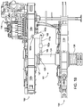
Figure 1A is a schematic perspective view of a tong assembly according to one embodiment of the present disclosure. -
Figure 1B is a schematic side view of the tong assembly ofFigure 1A . -
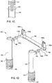
Figure 1C is a schematic partial sectional view of a support leg of the tong assembly ofFigure 1A . -
Figure 1D schematically illustrates a load transfer assembly of the tong assembly ofFigure 1A . -
Figure 2 is a block diagram illustrating a tubular makeup system according to embodiments disclosed herein. - The present disclosure generally relates to a tong assembly for making up and breaking out a tubular connection such as a connection between two tubulars in a tubular string. The tubular strings may be made of tubulars that form risers, casings, drill pipes or other tubulars in oil and gas wells. Embodiment of the present disclosures relates to a tong assembly having a power tong, a backup tong and a load transfer assembly connected between the power tong and the backup tong. The load transfer assembly includes a torque bar and sensors, such as load cells, to monitor the torque exerted on the tubular string by the tong assembly.
-
Figure 1A illustrates an embodiment of atong assembly 100 according to one embodiment of the present disclosure.Figure 1B is a schematic side view of thetong assembly 100. Thetong assembly 100 includes apower tong 102 and abackup tong 104. In operation, thepower tong 102 may be suspended from a handling tool or supported by a stand. Thepower tong 102 and thebackup tong 104 may be connected by aload transfer assembly 161. - The
power tong 102 may include aframe 108 with acentral opening 110 for receiving a tubular. Theframe 108 may include two or more sections movable relative to each other to open and close thecentral opening 110. In one embodiment, theframe 108 may include twofront sections back section 108c. Thefront sections back section 108 by hinges and pivotable about theback section 108c. In one embodiment, thefront sections pistons 109. - The
power tong 102 may further include arotor 112 disposed in theframe 108. Therotor 112 may be a segmented rotor. Therotor 112 may be coupled to amotor assembly 114.Jaws 116 may be attached to an inner diameter of therotor 112. Thejaws 116 may rotate with therotor 112 to rotate a tubular about acentral axis 101 during makeup and breakout of a tubular connection. Thejaws 116 may move radially relative to theframe 108 to secure and release a tubular or to accommodate tubulars of various diameters. In one embodiment, thejaws 116 may be driven using a hydraulic circuit. - The
backup tong 104 may be disposed underneath thepower tong 102. Thebackup tong 104 may include aframe 118 with acentral opening 120 for receiving a tubular. Theframe 118 may include two or more sections movable relative to each other to open and close thecentral opening 120. In one embodiment, theframe 118 may include twofront sections back section 118c. Thefront sections back section 118 by hinges and pivotable about theback section 118c. In one embodiment, thefront sections pistons 119. Thebackup tong 104 may includejaws 122 attached to theframe 118. Thejaws 122 may move radially relative to theframe 118 to secure and release a tubular or to accommodate tubular of various diameters. In one embodiment, thejaws 122 may be driven using a hydraulic circuit. - The
frame 118 of thebackup tong 104 may be movably coupled to supportlegs 124.Lower ends 125 of thesupport legs 124 are configured to stand a platform or other stationary planes. Thesupport legs 124 support thebackup tong 104 and prevent thebackup tong 104 from rotating during operation. In one embodiment, theframe 118 has through openings for receiving thesupport legs 124 therein. In one embodiment, theframe 118 may includesleeves 128 for receiving thesupport legs 124. In one embodiment, theframe 118 may be coupled to twosupport legs 124 that are symmetrically positioned about acentral axis 103 of thebackup tong 104. In one embodiment, thecentral axis 103 and central axis of the twosupport legs 124 may be within the same plane. Eachsupport leg 124 may include aspring member 126 disposed at lower ends 125. Weight and vertical load of thebackup tong 104 may rest on thespring members 126. Thespring members 126 allow thebackup tong 104 to be movable along thesupport legs 124 thus providing structure flexibility. - In one embodiment, the
power tong 102 may includealignment posts 127 extending from a lower side of theframe 108. When thetong assembly 100 is assembled, the alignment posts 127 may be inserted into thesupport legs 124 so that thecentral axis 101 of thepower tong 102 and thecentral axis 103 of thebackup tong 104 may be substantially aligned (seeFigure 1C ). The inner diameter of thesupport legs 124 is substantially larger than the outer diameter of the alignment posts 127 so that thepower tong 102 may move relative to thebackup tong 104 within a limited range without the alignment posts 127 contacting thesupport legs 124. When the alignment posts 127 do not contact thesupport legs 124, torsion and force are not transmitted between thesupport legs 124 and the alignment posts 127. In one embodiment, during assembly or transportation, pins 129 may be used to couple the alignment posts 127 to thesupport leg 124. However, during operation, thepins 129 are removed to allow relative movements between thepower tong 102 and thebackup tong 104 and avoid transmission of load between the alignment posts 127 and thesupport legs 124. - The
power tong 102 and thebackup tong 104 are connected through theload transfer assembly 161. Theload transfer assembly 161 may include twoarms links Fig. 1D ). The twoarms power tong 102 and extend downward from thepower tong 102. Thearms power tong 102 bypivot connections pivot connections central axis 101. Thetorque bar 164 couples the lower portion of the twoarms links support legs 124 and thearms link corresponding support leg 124 by apivot connection 166. Eachlink corresponding arm pivot connection 168. - When
power tong 102 applies a torque to rotate a first tubular causing a joint between the first tubular and a second tubular held by thebackup tong 104 to tighten or loosen, theload transfer assembly 161, coupled to thepower tong 102 and thebackup tong 104, provides reaction torques to prevent thepower tong 102 from moving relative to thebackup tong 104 along a horizontal plane. For example, during makeup, the torque applied by thepower tong 102 creates a reaction force which, because of thetorque bar 164 and thearms backup tong 104 via thelinks - According to embodiments of the present disclosure, each
arm load cell load cells respective arm load cells respective arm load cells load cell load cell first load cell 182a is configured to measure the applied force in tension during makeup, while thesecond load cell 182b is configured to measure the applied force in compression during makeup. During breakout, thesecond load cell 182b is configured to measure the applied force in tension, while thefirst load cell 182a is configured to measure the applied force in compression. -
Figure 2 is a block diagram illustrating atubular makeup system 200, according to one embodiment of the present disclosure. Thetubular makeup system 200 may include thetong assembly 100, a tong remote unit (TRU) 204, aturns counter 208,load cells control system 206. Thecontrol system 206 may communicate with theTRU 204 via an interface. Depending on sophistication of theTRU 204, the interface may be analog or digital. Alternatively, thecontrol system 206 may also serve as the TRU. - A programmable logic controller (PLC) 216 of the
control system 206 may monitor the turns countsignals 210 andtorque signals respective sensors PLC 216 may be any type of embedded computer device, for example, thePLC 216 may be replaced by a microcontroller unit (MCU), field programmable gate array (FPGA), application specific integrated circuit (ASIC), application specific instruction set processor (ASIP), digital signal processor (DSP), etc. The predetermined values 223-230 may be input by an technician for a particular connection. The predetermined values 223-230 may be input to thePLC 216 via aninput device 218, such as a keypad or any touch sensitive display. - Illustrative predetermined values 223-230 which may be input, by a technician or otherwise, include minimum and maximum delta gradient values 223, a
shoulder threshold gradient 224, adump torque value 226, minimum and maximum delta turnsvalues 228, minimum andmaximum torque values 230, andreference curve data 242. During makeup of the connection 1, various output may be observed by an technician on an output device, such as a video monitor, which may be one of a plurality ofoutput devices 220. The plurality ofoutput devices 220 may also include a printer, a plotter, an alarm, or other audio equipment. - Upon the occurrence of a predefined event(s), the
PLC 216 may output adump signal 222 to theTRU 204 to automatically shut down or reduce the torque exerted by thetong assembly 100. For example,dump signal 222 may be issued in response to the measured torque value reaching thedump torque 226 and/or a bad connection. - The comparison of measured turn count values and torque values with respect to predetermined values is performed by one or more functional units of the
PLC 216. The functional units may generally be implemented as hardware, software or a combination thereof. The functional units may include one or more of a torque-turnsplotter algorithm 232, aprocess monitor 234, atorque gradient calculator 236, asmoothing algorithm 238, asampler 240, adatabase 242 of reference curves, aconnection evaluator 252, and atarget detector 254. The process monitor 234 may include one or more of a threadengagement detection algorithm 244, aseal detection algorithm 246, ashoulder detection algorithm 248, and agraphical evaluator algorithm 250. Alternatively, the functional units may be performed by a single unit. As such, the functional units may be considered logical representations, rather than well-defined and individually distinguishable components of software or hardware. - In operation, one of the threaded members (e.g., tubular 2 and coupling 6) is rotated by the
power tong 102 while the other tubular 4 is held by thebackup tong 104. The applied torque and rotation are measured at regular intervals throughout the makeup. Depending on whether it is makeup or breakout operation, the tongremote unit 204 will select theappropriate load cell load cell link remote unit 204 will select thefirst load cell 170a, which will experience a tension force since the makeup torque is applied clockwise. In turn, the measured force may be used to calculate the applied torque by thecontrol system 206 orTRU 204. If it is a breakout process, then the tongremote unit 204 will select thesecond load cell 182b, which will experience a tension force since the breakout torque is applied counterclockwise. In one embodiment, theTRU 204 will select theload cell TRU 204. In another embodiment, theTRU 204 may select theload cell TRU 204 will select thefirst load cell 182a. A negative turns value will indicate a breakout process, in which case theTRU 204 will select thesecond load cell 182b. - The frequency with which torque and rotation are measured may be specified by the
sampler 240. Thesampler 240 may be configurable, so that a technician may input a desired sampling frequency. The torque and rotation values may be stored as a paired set in a buffer area of memory. Further, the rate of change of torque with respect to rotation (hereinafter "torque gradient") may be calculated for each paired set of measurements by thetorque gradient calculator 236. Optionally, the compression force experienced by thelink 170b may be measured by thesecond load cell 182b and stored with the pair set of measurements. The smoothingalgorithm 238 may operate to smooth the torque-turns curve 50 and/or torque gradient curve 50a (e.g., by way of a running average). These values (torque, rotation, and torque gradient) may then be plotted by theplotter 232 for display on theoutput device 220. - The values (torque, rotation, and torque gradient) may then be compared by the
connection evaluator 252, either continuously or at selected events, with predetermined values, such as the values 223-230. Based on the comparison of the measured and/or calculated values with the predefined values 223-230, the process monitor 234 may determine the occurrence of various events and theconnection evaluator 252 may determine whether to continue rotation or abort the makeup. The threadengagement detection algorithm 244 may monitor for thread engagement of thetubulars 2, 4. Upon detection of thread engagement a first marker is stored. The marker may be quantified, for example, by time, rotation, torque, the torque gradient, or a combination of any such quantifications. During continued rotation, theseal detection algorithm 246 monitors for the seal condition. This may be accomplished by comparing the calculated torque gradient with a predetermined threshold seal condition value. A second marker indicating the seal condition may be stored if/when the seal condition is detected. At this point, the torque value at the seal condition may be evaluated by theconnection evaluator 252. - For example, a determination may be made as to whether the turns value and/or torque value are within specified limits. The specified limits may be predetermined, or based off of a value measured during makeup. If the
connection evaluator 252 determines a bad connection, rotation may be terminated. Otherwise, rotation continues and theshoulder detection algorithm 248 monitors for the shoulder position. This may be accomplished by comparing the calculated torque gradient with theshoulder threshold gradient 224. When the shoulder position is detected, a third marker indicating the shoulder position is stored. Theconnection evaluator 252 may then determine whether the torque value at the shoulder position is acceptable by comparing to the respective input torque values 230. - Alternatively, a delta turns value may be entered instead of the
dump torque 226. Thetarget detector 254 may then calculate a target turns value using the shoulder turns and the delta turns value (target turns equals shoulder turns plus delta turns). - During one or more steps of the torque monitoring process, the
connection evaluator 252 may verify the torque measured by thefirst load cell 182a. For example, during makeup, thelink 170b experiences a compressive force, which may be measured by thesecond load cell 182b. The torque value derived from the compression measurement at thesecond load cell 182b may be compared to the torque value of the first load cell 182. If the torque value measured by thesecond load cell 182b is determined to be within 20% of the torque value measured by thefirst load cell 182a, then theconnection evaluator 252 will allow the makeup to continue. Otherwise, the makeup process may be stopped. In another example, the makeup process may continue if the torque value of thesecond load cell 182b is within 15%, within 10%, or within 5% of the torque value measured by thefirst load cell 182a. If a breakout operation is being performed, then the torque value from thefirst load cell 182a may be used to verify the torque value from thesecond load cell 182b. - In another embodiment, during an operation, the
tong assembly 100 is first moved to the location of the tubular string to be operated. Thetong assembly 100 may be moved using an overhead handling tool or a track on the platform. Theframes power tong 102 and thebackup tong 104 may be in the open position to receive the tubular string in theopenings front sections front sections tong assembly 100 is being moved. Once thetong assembly 100 is in position, i.e. thecentral axis 101 of thetong assembly 100 aligns with longitudinal axis of the tubular string. Thefront sections front sections jaws 116 and thejaws 122 may secure the tubular string. When thetong assembly 100 is in the position for making up or breaking out a connection, the tubular string is secured by thejaws 122 of thebackup tong 104 and the tubular section to be joined or removed is secured by thejaws 116 of thepower tong 102. - To makeup the joint, the first tubular is generally grounded to the work floor, for example by the slips for the work floor. The
jaws 122 of thebackup tong 104 clamp to the first tubular so that thebackup tong 104 would not rotate while thejaws 116 of thepower tong 102 clamp to the second tubular and rotate the second tubular relative to the first tubular. - The
power tong 102 rotates the second tubular clockwise during makeup. The torque generated by the clockwise rotation of thejaws 116 of thepower tong 102 is transferred to thearms pivot connections arms pivot connections 180a. 180b and thecentral axis 101. The forces are transferred along the paths of thearms links support legs 124 to thebackup tong 104. Thestationary backup tong 104 exerts reactions forces along the same paths to thepower tong 102 to prevent thepower tong 102 from rotating. The force acting onlink 170a is a tension force, and the force acting onlink 170b is a compression force. - For makeup, the
first load cell 182a is selected to measure the torque value applied by thepower tong 102. The force measurements by theload cell 182a are used to monitor the torque applied to the tubular connection during operation. For example, the force measurements are correlated to torque values by the tong control system. Monitoring the torque measurements of theload cell 182a may prevent the tubular joints from being too loose or too tight. For example, an upper torque and a lower torque may be used to control the tightness of the joints. For example, during makeup, the torque measurement of theload cell 182a may be monitored to continuously rotate thepower tong 102 when the measurement is lower than the lower torque and stop the rotation of thepower tong 102 or reverse the rotation of thepower tong 102 when the torque measurement by theload cell 182a reaches or exceeds the upper torque. Additionally, the torque measurement of theload cell 182a may also be used to achieve uniform tightness among the joints in a tubular string. - The torque measurement of the
second load cell 182b may be used to verify the torque measured by thefirst load cell 182a. For example, if the torque measurement of thesecond load cell 182b is within 15% of thefirst load cell 182a, then the makeup operation may continue. - To breakout the joint, the first tubular is generally grounded to the work floor, for example by the slips for the work floor. The
jaws 122 of thebackup tong 104 clamp to the first tubular so that thebackup tong 104 would not rotate while thejaws 116 of thepower tong 102 clamp to the second tubular and rotate the second tubular relative to the first tubular. - The
power tong 102 rotates the second tubular counterclockwise during makeup. The torque generated by the counterclockwise rotation of thejaws 116 of thepower tong 102 is transferred to thearms pivot connections arms pivot connections 180a. 180b and thecentral axis 101. The forces are transferred along the paths of thearms links support legs 124 to thebackup tong 104. Thestationary backup tong 104 exerts reactions forces along the same paths to thepower tong 102 to prevent thepower tong 102 from rotating. The force acting onlink 170b is a tension force, and the force acting onlink 170a is a compression force. - For breakout, the
second load cell 182b is selected to measure the torque value applied by thepower tong 102. The force measurements by thesecond load cell 182b are used to monitor the torque applied to the tubular connection during operation. For example, the force measurements are correlated to torque values by the tong control system. Monitoring the torque measurements of thesecond load cell 182b may prevent the tubular joints from being too loose or too tight. For example, an upper torque and a lower torque may be used to control the tightness of the joints. For example, during makeup, the torque measurement of thesecond load cell 182b may be monitored to continuously rotate thepower tong 102 when the measurement is lower than the lower torque and stop the rotation of thepower tong 102 or reverse the rotation of thepower tong 102 when the torque measurement by thesecond load cell 182b reach or exceed the upper torque. Additionally, the torque measurement of thesecond load cell 182b may also be used to achieve uniform tightness among the joints in a tubular string. - The torque measurement of the
first load cell 182a may be used to verify the torque measured by thesecond load cell 182b. For example, if the torque measurement of thefirst load cell 182a is within 15% of thesecond load cell 182b, then the makeup operation may continue. - In one embodiment, a tubular handling apparatus includes a power tong; a backup tong; and a load transfer assembly connected between the power tong and the backup tong. The load transfer assembly includes a first link having a first load cell positioned to measure a first force exerted on the first link; and a second link having a second load cell positioned to measure a second force exerted on the second link. The tubular handling apparatus may also include a tong control assembly configured to select the first load cell for use in a tubular makeup operation and to select the second load cell for use in a tubular breakout operation.
- In one or more embodiments described herein, the first force exerted on the first link during the tubular makeup process is a tension force.
- In one or more embodiments described herein, the second force exerted on the second link during the tubular breakout process is a tension force.
- In one or more embodiments described herein, the load transfer assembly further includes a first arm coupled to the first link and the power tong; and a second arm coupled to the second link and the power tong.
- In one or more embodiments described herein, the apparatus includes a torque bar coupled to the first arm and the second arm.
- In one or more embodiments described herein, the first load cell is disposed along the longitudinal axis of the first link.
- In one or more embodiments described herein, the first force and the second force are in opposite directions.
- In another embodiment, a method of measuring a torque applied between a first tubular and a second tubular includes gripping the first tubular using a power tong; gripping the second tubular using a backup tong; applying a torque to the first tubular using a power tong; measuring the torque using a first load cell if the first tubular is being connected to the second tubular; and measuring the torque using a second load cell if the first tubular is being disconnected from the second tubular.
- In another embodiment, a method of measuring a torque applied between a first tubular and a second tubular includes gripping the first tubular using a power tong; gripping the second tubular using a backup tong; applying a torque to the first tubular using a power tong; measuring a tension force using a first load cell; determining the torque applied using the measured tension force; measuring a compressive force using a second load cell; and verifying the torque applied using the compressive force.
- In another embodiment, a method of measuring a torque applied by a tong assembly includes applying a clockwise torque using a power tong of the tong assembly; measuring a first tension force using a first load cell; determining the clockwise torque using the first tension force; applying a counterclockwise torque using the power tong; measuring a second tension force using a first load cell; and determining the counterclockwise torque using the second tension force.
- In one or more embodiments described herein, the first load cell is configured to measure a tension force while the first tubular is being connected to the second tubular, and measuring the torque comprises calculating the torque based on the tension force measured.
- In one or more embodiments described herein, the second load cell is configured to measure a tension force while the first tubular is being disconnected from the second tubular, and measuring the torque comprises calculating the torque based on the tension force measured.
- In one or more embodiments described herein, the method includes verifying the torque using the second load cell.
- In one or more embodiments described herein, the second load cell is configured to measure a compression force while the first tubular is being connected to the second tubular, and the method includes calculating a second torque based on the compression force measured; and comparing the torque measured to the second torque.
- In one or more embodiments described herein, the method includes determining whether the first tubular is being connected to the second tubular.
- In one or more embodiments described herein, the method includes selecting the first load cell or the second load cell based on the determination.
- In one or more embodiments described herein, the method includes measuring a turns value to determine whether the first tubular is being connected to the second tubular.
- While the foregoing is directed to embodiments of the present disclosure, other and further embodiments may be devised without departing from the basic scope thereof, and the scope of the present disclosure is determined by the claims that follow.
Claims (15)
- A tubular handling apparatus, comprising:a power tong;a backup tong;a load transfer assembly connected between the power tong and the backup tong, wherein the load transfer assembly includes:a first link having a first load cell positioned to measure a first force exerted on the first link; and.a second link having a second load cell positioned to measure a second force exerted on the second link; anda tong control assembly configured to select the first load cell for use in a tubular makeup operation and to select the second load cell for use in a tubular breakout operation.
- The apparatus of claim 1, wherein the first force exerted on the first link during the tubular makeup process is a tension force.
- The apparatus of claim 1 or 2, wherein the second force exerted on the second link during the tubular breakout process is a tension force.
- The apparatus of any preceding claim, wherein the load transfer assembly further comprises:a first arm coupled to the first link and the power tong; anda second arm coupled to the second link and the power tong.
- The apparatus of claim 4, further comprising a torque bar coupled to the first arm and the second arm.
- The apparatus of any preceding claim, wherein the first load cell is disposed along the longitudinal axis of the first link.
- The apparatus of any preceding claim, wherein the first force and the second force are in opposite directions.
- A method of measuring a torque applied between a first tubular and a second tubular, comprising:gripping the first tubular using a power tong;gripping the second tubular using a backup tong;applying a torque to the first tubular using a power tong;measuring the torque using a first load cell if the first tubular is being connected to the second tubular; andmeasuring the torque using a second load cell if the first tubular is being disconnected from the second tubular.
- The method of claim 8, wherein the first load cell is configured to measure a tension force while the first tubular is being connected to the second tubular, and measuring the torque comprises calculating the torque based on the tension force measured.
- The method of claim 8 or 9, wherein the second load cell is configured to measure a tension force while the first tubular is being disconnected from the second tubular, and measuring the torque comprises calculating the torque based on the tension force measured.
- The method of claim 8, 9 or 10, further comprising verifying the torque using the second load cell.
- The method of claim 11, wherein the second load cell is configured to measure a compression force while the first tubular is being connected to the second tubular, and the method includes:calculating a second torque based on the compression force measured; andcomparing the torque measured to the second torque.
- The method of any one of claims 8 to 12, further comprising determining whether the first tubular is being connected to the second tubular, and optionally selecting the first load cell or the second load cell based on the determination.
- The method of any one of claims 8 to 12, further comprising measuring a turns value to determine whether the first tubular is being connected to the second tubular.
- A method of measuring a torque applied by a tong assembly, comprising:applying a clockwise torque using a power tong of the tong assembly;measuring a first tension force using a first load cell;determining the clockwise torque using the first tension force;applying a counterclockwise torque using the power tong;measuring a second tension force using a first load cell; anddetermining the counterclockwise torque using the second tension force.
Applications Claiming Priority (1)
| Application Number | Priority Date | Filing Date | Title |
|---|---|---|---|
| US15/815,590 US10605016B2 (en) | 2017-11-16 | 2017-11-16 | Tong assembly |
Publications (2)
| Publication Number | Publication Date |
|---|---|
| EP3502409A1 true EP3502409A1 (en) | 2019-06-26 |
| EP3502409B1 EP3502409B1 (en) | 2020-10-07 |
Family
ID=64172328
Family Applications (1)
| Application Number | Title | Priority Date | Filing Date |
|---|---|---|---|
| EP18204251.5A Active EP3502409B1 (en) | 2017-11-16 | 2018-11-05 | Tong assembly |
Country Status (5)
| Country | Link |
|---|---|
| US (1) | US10605016B2 (en) |
| EP (1) | EP3502409B1 (en) |
| AU (1) | AU2018256644B2 (en) |
| CA (1) | CA3022999C (en) |
| MX (1) | MX2018013977A (en) |
Families Citing this family (6)
| Publication number | Priority date | Publication date | Assignee | Title |
|---|---|---|---|---|
| US11613942B2 (en) | 2018-03-12 | 2023-03-28 | The Charles Machine Works, Inc. | Torque-dependent oscillation of a dual-pipe inner section |
| US11053756B2 (en) * | 2018-03-12 | 2021-07-06 | The Charles Machine Works, Inc. | Torque-dependent oscillation of a dual-pipe inner pipe section |
| US11592346B2 (en) | 2020-02-26 | 2023-02-28 | Weatherford Technology Holdings, Llc | Multi-range load cell |
| US11136838B1 (en) | 2020-04-22 | 2021-10-05 | Weatherford Technology Holdings, Llc | Load cell for a tong assembly |
| US12134942B2 (en) | 2023-03-10 | 2024-11-05 | Baker Hughes Oilfield Operations Llc | Control of tubular connections based on estimation of turns remaining |
| CN118686559B (en) * | 2024-08-28 | 2024-12-24 | 胜利油田胜机石油装备有限公司 | Automatic hydraulic clamp clamping and slipping protection device for intelligent well workover operation of oil field and control method |
Citations (4)
| Publication number | Priority date | Publication date | Assignee | Title |
|---|---|---|---|---|
| US4649777A (en) * | 1984-06-21 | 1987-03-17 | David Buck | Back-up power tongs |
| WO2004079148A2 (en) * | 2003-03-05 | 2004-09-16 | Weatherford/Lamb, Inc. | Tong |
| US20110030512A1 (en) * | 2009-08-06 | 2011-02-10 | Frank's Casing Crew And Rental Tools, Inc. | Tubular Joining Apparatus |
| WO2016191067A1 (en) * | 2015-05-28 | 2016-12-01 | Weatherford Technology Holdings, Llc | Tong assembly with torque measurement |
Family Cites Families (12)
| Publication number | Priority date | Publication date | Assignee | Title |
|---|---|---|---|---|
| US5245877A (en) | 1991-03-12 | 1993-09-21 | Weatherford U.S., Inc. | Tong load cell assembly |
| US5542318A (en) | 1994-04-28 | 1996-08-06 | Wesch, Jr.; William E. | Bi-directional gripping apparatus |
| US5845549A (en) * | 1995-12-20 | 1998-12-08 | Frank's Casing Crew And Rental Tools, Inc. | Power tong gripping ring mechanism |
| US6082224A (en) * | 1997-01-29 | 2000-07-04 | Weatherford/Lamb, Inc. | Power tong |
| CA2269393C (en) * | 1999-04-21 | 2008-02-12 | Universe Machine Corporation | Power tong and backup tong system |
| US7413398B2 (en) | 2003-04-01 | 2008-08-19 | Mccoy Corporation | Power tong positioner |
| US7188547B1 (en) * | 2005-12-23 | 2007-03-13 | Varco I/P, Inc. | Tubular connect/disconnect apparatus |
| CA2741532C (en) | 2008-10-22 | 2014-01-28 | Frank's International, Inc. | External grip tubular running tool |
| US20120323500A1 (en) | 2011-06-20 | 2012-12-20 | Alberta Custom Technologies Ltd. | Apparatuses for monitoring power tong operation |
| WO2015050931A1 (en) * | 2013-10-01 | 2015-04-09 | Nabors Corporate Services | Automated roughneck |
| EP3337945B1 (en) | 2015-08-20 | 2023-05-10 | Weatherford Technology Holdings, LLC | Top drive torque measurement device |
| US10337264B2 (en) * | 2016-11-21 | 2019-07-02 | Weatherford Technology Holdings, Llc | Movable tong assembly |
-
2017
- 2017-11-16 US US15/815,590 patent/US10605016B2/en active Active
-
2018
- 2018-11-01 CA CA3022999A patent/CA3022999C/en active Active
- 2018-11-02 AU AU2018256644A patent/AU2018256644B2/en active Active
- 2018-11-05 EP EP18204251.5A patent/EP3502409B1/en active Active
- 2018-11-14 MX MX2018013977A patent/MX2018013977A/en unknown
Patent Citations (4)
| Publication number | Priority date | Publication date | Assignee | Title |
|---|---|---|---|---|
| US4649777A (en) * | 1984-06-21 | 1987-03-17 | David Buck | Back-up power tongs |
| WO2004079148A2 (en) * | 2003-03-05 | 2004-09-16 | Weatherford/Lamb, Inc. | Tong |
| US20110030512A1 (en) * | 2009-08-06 | 2011-02-10 | Frank's Casing Crew And Rental Tools, Inc. | Tubular Joining Apparatus |
| WO2016191067A1 (en) * | 2015-05-28 | 2016-12-01 | Weatherford Technology Holdings, Llc | Tong assembly with torque measurement |
Also Published As
| Publication number | Publication date |
|---|---|
| EP3502409B1 (en) | 2020-10-07 |
| US10605016B2 (en) | 2020-03-31 |
| CA3022999A1 (en) | 2019-05-16 |
| BR102018073614A2 (en) | 2019-10-01 |
| CA3022999C (en) | 2023-03-21 |
| US20190145195A1 (en) | 2019-05-16 |
| AU2018256644B2 (en) | 2020-07-02 |
| AU2018256644A1 (en) | 2019-05-30 |
| MX2018013977A (en) | 2019-05-27 |
Similar Documents
| Publication | Publication Date | Title |
|---|---|---|
| EP3502409B1 (en) | Tong assembly | |
| US10808472B2 (en) | Method and system for evaluating tubular makeup | |
| US7296623B2 (en) | Methods and apparatus for applying torque and rotation to connections | |
| AU2017351066B2 (en) | Automated load cell identification | |
| CA2451263C (en) | Methods and apparatus for applying torque and rotation to connections | |
| US20200199952A1 (en) | Autonomous connection makeup and evaluation | |
| AU2016266753B2 (en) | Tong assembly with torque measurement | |
| EP4139557B1 (en) | Load cell for a tong assembly | |
| KR20190121308A (en) | Joint recognition system | |
| US10808474B2 (en) | Method and system for evaluating tubular makeup | |
| BR102018073614B1 (en) | TUBULAR HANDLING APPLIANCE AND METHOD OF MEASURING A TORQUE APPLIED BETWEEN A FIRST TUBULAR AND A SECOND TUBULAR |
Legal Events
| Date | Code | Title | Description |
|---|---|---|---|
| PUAI | Public reference made under article 153(3) epc to a published international application that has entered the european phase |
Free format text: ORIGINAL CODE: 0009012 |
|
| STAA | Information on the status of an ep patent application or granted ep patent |
Free format text: STATUS: THE APPLICATION HAS BEEN PUBLISHED |
|
| AK | Designated contracting states |
Kind code of ref document: A1 Designated state(s): AL AT BE BG CH CY CZ DE DK EE ES FI FR GB GR HR HU IE IS IT LI LT LU LV MC MK MT NL NO PL PT RO RS SE SI SK SM TR |
|
| AX | Request for extension of the european patent |
Extension state: BA ME |
|
| STAA | Information on the status of an ep patent application or granted ep patent |
Free format text: STATUS: REQUEST FOR EXAMINATION WAS MADE |
|
| 17P | Request for examination filed |
Effective date: 20191205 |
|
| RBV | Designated contracting states (corrected) |
Designated state(s): AL AT BE BG CH CY CZ DE DK EE ES FI FR GB GR HR HU IE IS IT LI LT LU LV MC MK MT NL NO PL PT RO RS SE SI SK SM TR |
|
| GRAP | Despatch of communication of intention to grant a patent |
Free format text: ORIGINAL CODE: EPIDOSNIGR1 |
|
| STAA | Information on the status of an ep patent application or granted ep patent |
Free format text: STATUS: GRANT OF PATENT IS INTENDED |
|
| INTG | Intention to grant announced |
Effective date: 20200512 |
|
| 111Z | Information provided on other rights and legal means of execution |
Free format text: AL AT BE BG CH CY CZ DE DK EE ES FI FR GB GR HR HU IE IS IT LT LU LV MC MK MT NL NO PL PT RO RS SE SI SK SM TR AL AT BE BG CH CY CZ DE DK EE ES FI FR GB GR HR HU IE IS IT LT LU LV MC MK MT NL NO PL PT RO RS SE SI SK SM TR Effective date: 20200511 |
|
| GRAS | Grant fee paid |
Free format text: ORIGINAL CODE: EPIDOSNIGR3 |
|
| GRAA | (expected) grant |
Free format text: ORIGINAL CODE: 0009210 |
|
| STAA | Information on the status of an ep patent application or granted ep patent |
Free format text: STATUS: THE PATENT HAS BEEN GRANTED |
|
| AK | Designated contracting states |
Kind code of ref document: B1 Designated state(s): AL AT BE BG CH CY CZ DE DK EE ES FI FR GB GR HR HU IE IS IT LI LT LU LV MC MK MT NL NO PL PT RO RS SE SI SK SM TR |
|
| REG | Reference to a national code |
Ref country code: GB Ref legal event code: FG4D |
|
| REG | Reference to a national code |
Ref country code: CH Ref legal event code: EP Ref country code: AT Ref legal event code: REF Ref document number: 1321328 Country of ref document: AT Kind code of ref document: T Effective date: 20201015 |
|
| REG | Reference to a national code |
Ref country code: IE Ref legal event code: FG4D |
|
| REG | Reference to a national code |
Ref country code: DE Ref legal event code: R096 Ref document number: 602018008480 Country of ref document: DE |
|
| R11X | Information provided on other rights and legal means of execution (corrected) |
Free format text: AL AT BE BG CH CY CZ DE DK EE ES FI FR GB GR HR HU IE IS IT LT LU LV MC MK MT NL NO PL PT RO RS SE SI SK SM TR Effective date: 20200511 |
|
| REG | Reference to a national code |
Ref country code: GB Ref legal event code: 732E Free format text: REGISTERED BETWEEN 20201126 AND 20201202 |
|
| REG | Reference to a national code |
Ref country code: NL Ref legal event code: FP |
|
| REG | Reference to a national code |
Ref country code: NO Ref legal event code: T2 Effective date: 20201007 |
|
| REG | Reference to a national code |
Ref country code: AT Ref legal event code: MK05 Ref document number: 1321328 Country of ref document: AT Kind code of ref document: T Effective date: 20201007 |
|
| REG | Reference to a national code |
Ref country code: GB Ref legal event code: 732E Free format text: REGISTERED BETWEEN 20210225 AND 20210303 |
|
| PG25 | Lapsed in a contracting state [announced via postgrant information from national office to epo] |
Ref country code: PT Free format text: LAPSE BECAUSE OF FAILURE TO SUBMIT A TRANSLATION OF THE DESCRIPTION OR TO PAY THE FEE WITHIN THE PRESCRIBED TIME-LIMIT Effective date: 20210208 Ref country code: RS Free format text: LAPSE BECAUSE OF FAILURE TO SUBMIT A TRANSLATION OF THE DESCRIPTION OR TO PAY THE FEE WITHIN THE PRESCRIBED TIME-LIMIT Effective date: 20201007 Ref country code: FI Free format text: LAPSE BECAUSE OF FAILURE TO SUBMIT A TRANSLATION OF THE DESCRIPTION OR TO PAY THE FEE WITHIN THE PRESCRIBED TIME-LIMIT Effective date: 20201007 Ref country code: GR Free format text: LAPSE BECAUSE OF FAILURE TO SUBMIT A TRANSLATION OF THE DESCRIPTION OR TO PAY THE FEE WITHIN THE PRESCRIBED TIME-LIMIT Effective date: 20210108 |
|
| REG | Reference to a national code |
Ref country code: LT Ref legal event code: MG4D |
|
| PG25 | Lapsed in a contracting state [announced via postgrant information from national office to epo] |
Ref country code: AT Free format text: LAPSE BECAUSE OF FAILURE TO SUBMIT A TRANSLATION OF THE DESCRIPTION OR TO PAY THE FEE WITHIN THE PRESCRIBED TIME-LIMIT Effective date: 20201007 Ref country code: ES Free format text: LAPSE BECAUSE OF FAILURE TO SUBMIT A TRANSLATION OF THE DESCRIPTION OR TO PAY THE FEE WITHIN THE PRESCRIBED TIME-LIMIT Effective date: 20201007 Ref country code: SE Free format text: LAPSE BECAUSE OF FAILURE TO SUBMIT A TRANSLATION OF THE DESCRIPTION OR TO PAY THE FEE WITHIN THE PRESCRIBED TIME-LIMIT Effective date: 20201007 Ref country code: PL Free format text: LAPSE BECAUSE OF FAILURE TO SUBMIT A TRANSLATION OF THE DESCRIPTION OR TO PAY THE FEE WITHIN THE PRESCRIBED TIME-LIMIT Effective date: 20201007 Ref country code: IS Free format text: LAPSE BECAUSE OF FAILURE TO SUBMIT A TRANSLATION OF THE DESCRIPTION OR TO PAY THE FEE WITHIN THE PRESCRIBED TIME-LIMIT Effective date: 20210207 Ref country code: LV Free format text: LAPSE BECAUSE OF FAILURE TO SUBMIT A TRANSLATION OF THE DESCRIPTION OR TO PAY THE FEE WITHIN THE PRESCRIBED TIME-LIMIT Effective date: 20201007 Ref country code: BG Free format text: LAPSE BECAUSE OF FAILURE TO SUBMIT A TRANSLATION OF THE DESCRIPTION OR TO PAY THE FEE WITHIN THE PRESCRIBED TIME-LIMIT Effective date: 20210107 |
|
| PG25 | Lapsed in a contracting state [announced via postgrant information from national office to epo] |
Ref country code: HR Free format text: LAPSE BECAUSE OF FAILURE TO SUBMIT A TRANSLATION OF THE DESCRIPTION OR TO PAY THE FEE WITHIN THE PRESCRIBED TIME-LIMIT Effective date: 20201007 |
|
| REG | Reference to a national code |
Ref country code: DE Ref legal event code: R097 Ref document number: 602018008480 Country of ref document: DE |
|
| PG25 | Lapsed in a contracting state [announced via postgrant information from national office to epo] |
Ref country code: LT Free format text: LAPSE BECAUSE OF FAILURE TO SUBMIT A TRANSLATION OF THE DESCRIPTION OR TO PAY THE FEE WITHIN THE PRESCRIBED TIME-LIMIT Effective date: 20201007 Ref country code: MC Free format text: LAPSE BECAUSE OF FAILURE TO SUBMIT A TRANSLATION OF THE DESCRIPTION OR TO PAY THE FEE WITHIN THE PRESCRIBED TIME-LIMIT Effective date: 20201007 Ref country code: LU Free format text: LAPSE BECAUSE OF NON-PAYMENT OF DUE FEES Effective date: 20201105 Ref country code: RO Free format text: LAPSE BECAUSE OF FAILURE TO SUBMIT A TRANSLATION OF THE DESCRIPTION OR TO PAY THE FEE WITHIN THE PRESCRIBED TIME-LIMIT Effective date: 20201007 Ref country code: CZ Free format text: LAPSE BECAUSE OF FAILURE TO SUBMIT A TRANSLATION OF THE DESCRIPTION OR TO PAY THE FEE WITHIN THE PRESCRIBED TIME-LIMIT Effective date: 20201007 Ref country code: EE Free format text: LAPSE BECAUSE OF FAILURE TO SUBMIT A TRANSLATION OF THE DESCRIPTION OR TO PAY THE FEE WITHIN THE PRESCRIBED TIME-LIMIT Effective date: 20201007 Ref country code: SK Free format text: LAPSE BECAUSE OF FAILURE TO SUBMIT A TRANSLATION OF THE DESCRIPTION OR TO PAY THE FEE WITHIN THE PRESCRIBED TIME-LIMIT Effective date: 20201007 Ref country code: SM Free format text: LAPSE BECAUSE OF FAILURE TO SUBMIT A TRANSLATION OF THE DESCRIPTION OR TO PAY THE FEE WITHIN THE PRESCRIBED TIME-LIMIT Effective date: 20201007 |
|
| REG | Reference to a national code |
Ref country code: BE Ref legal event code: MM Effective date: 20201130 |
|
| PLBE | No opposition filed within time limit |
Free format text: ORIGINAL CODE: 0009261 |
|
| STAA | Information on the status of an ep patent application or granted ep patent |
Free format text: STATUS: NO OPPOSITION FILED WITHIN TIME LIMIT |
|
| PG25 | Lapsed in a contracting state [announced via postgrant information from national office to epo] |
Ref country code: DK Free format text: LAPSE BECAUSE OF FAILURE TO SUBMIT A TRANSLATION OF THE DESCRIPTION OR TO PAY THE FEE WITHIN THE PRESCRIBED TIME-LIMIT Effective date: 20201007 |
|
| REG | Reference to a national code |
Ref country code: GB Ref legal event code: 732E Free format text: REGISTERED BETWEEN 20210812 AND 20210818 |
|
| 26N | No opposition filed |
Effective date: 20210708 |
|
| PG25 | Lapsed in a contracting state [announced via postgrant information from national office to epo] |
Ref country code: AL Free format text: LAPSE BECAUSE OF FAILURE TO SUBMIT A TRANSLATION OF THE DESCRIPTION OR TO PAY THE FEE WITHIN THE PRESCRIBED TIME-LIMIT Effective date: 20201007 Ref country code: FR Free format text: LAPSE BECAUSE OF NON-PAYMENT OF DUE FEES Effective date: 20201207 Ref country code: IE Free format text: LAPSE BECAUSE OF NON-PAYMENT OF DUE FEES Effective date: 20201105 Ref country code: IT Free format text: LAPSE BECAUSE OF FAILURE TO SUBMIT A TRANSLATION OF THE DESCRIPTION OR TO PAY THE FEE WITHIN THE PRESCRIBED TIME-LIMIT Effective date: 20201007 |
|
| PG25 | Lapsed in a contracting state [announced via postgrant information from national office to epo] |
Ref country code: SI Free format text: LAPSE BECAUSE OF FAILURE TO SUBMIT A TRANSLATION OF THE DESCRIPTION OR TO PAY THE FEE WITHIN THE PRESCRIBED TIME-LIMIT Effective date: 20201007 |
|
| PG25 | Lapsed in a contracting state [announced via postgrant information from national office to epo] |
Ref country code: IS Free format text: LAPSE BECAUSE OF FAILURE TO SUBMIT A TRANSLATION OF THE DESCRIPTION OR TO PAY THE FEE WITHIN THE PRESCRIBED TIME-LIMIT Effective date: 20210207 Ref country code: TR Free format text: LAPSE BECAUSE OF FAILURE TO SUBMIT A TRANSLATION OF THE DESCRIPTION OR TO PAY THE FEE WITHIN THE PRESCRIBED TIME-LIMIT Effective date: 20201007 Ref country code: MT Free format text: LAPSE BECAUSE OF FAILURE TO SUBMIT A TRANSLATION OF THE DESCRIPTION OR TO PAY THE FEE WITHIN THE PRESCRIBED TIME-LIMIT Effective date: 20201007 Ref country code: CY Free format text: LAPSE BECAUSE OF FAILURE TO SUBMIT A TRANSLATION OF THE DESCRIPTION OR TO PAY THE FEE WITHIN THE PRESCRIBED TIME-LIMIT Effective date: 20201007 |
|
| PG25 | Lapsed in a contracting state [announced via postgrant information from national office to epo] |
Ref country code: MK Free format text: LAPSE BECAUSE OF FAILURE TO SUBMIT A TRANSLATION OF THE DESCRIPTION OR TO PAY THE FEE WITHIN THE PRESCRIBED TIME-LIMIT Effective date: 20201007 |
|
| REG | Reference to a national code |
Ref country code: CH Ref legal event code: PL |
|
| PG25 | Lapsed in a contracting state [announced via postgrant information from national office to epo] |
Ref country code: BE Free format text: LAPSE BECAUSE OF NON-PAYMENT OF DUE FEES Effective date: 20201130 |
|
| PG25 | Lapsed in a contracting state [announced via postgrant information from national office to epo] |
Ref country code: LI Free format text: LAPSE BECAUSE OF NON-PAYMENT OF DUE FEES Effective date: 20220701 Ref country code: CH Free format text: LAPSE BECAUSE OF NON-PAYMENT OF DUE FEES Effective date: 20220701 |
|
| P01 | Opt-out of the competence of the unified patent court (upc) registered |
Effective date: 20230922 |
|
| PGFP | Annual fee paid to national office [announced via postgrant information from national office to epo] |
Ref country code: NL Payment date: 20250912 Year of fee payment: 8 |
|
| PGFP | Annual fee paid to national office [announced via postgrant information from national office to epo] |
Ref country code: GB Payment date: 20250911 Year of fee payment: 8 |
|
| PGFP | Annual fee paid to national office [announced via postgrant information from national office to epo] |
Ref country code: DE Payment date: 20250910 Year of fee payment: 8 |
|
| PGFP | Annual fee paid to national office [announced via postgrant information from national office to epo] |
Ref country code: NO Payment date: 20251113 Year of fee payment: 8 |