EP3502305A1 - Line-of-sight coating fixture and apparatus - Google Patents
Line-of-sight coating fixture and apparatus Download PDFInfo
- Publication number
- EP3502305A1 EP3502305A1 EP18214948.4A EP18214948A EP3502305A1 EP 3502305 A1 EP3502305 A1 EP 3502305A1 EP 18214948 A EP18214948 A EP 18214948A EP 3502305 A1 EP3502305 A1 EP 3502305A1
- Authority
- EP
- European Patent Office
- Prior art keywords
- workpiece
- support structure
- platter
- disposed
- periphery
- Prior art date
- Legal status (The legal status is an assumption and is not a legal conclusion. Google has not performed a legal analysis and makes no representation as to the accuracy of the status listed.)
- Granted
Links
Images



Classifications
-
- C—CHEMISTRY; METALLURGY
- C23—COATING METALLIC MATERIAL; COATING MATERIAL WITH METALLIC MATERIAL; CHEMICAL SURFACE TREATMENT; DIFFUSION TREATMENT OF METALLIC MATERIAL; COATING BY VACUUM EVAPORATION, BY SPUTTERING, BY ION IMPLANTATION OR BY CHEMICAL VAPOUR DEPOSITION, IN GENERAL; INHIBITING CORROSION OF METALLIC MATERIAL OR INCRUSTATION IN GENERAL
- C23C—COATING METALLIC MATERIAL; COATING MATERIAL WITH METALLIC MATERIAL; SURFACE TREATMENT OF METALLIC MATERIAL BY DIFFUSION INTO THE SURFACE, BY CHEMICAL CONVERSION OR SUBSTITUTION; COATING BY VACUUM EVAPORATION, BY SPUTTERING, BY ION IMPLANTATION OR BY CHEMICAL VAPOUR DEPOSITION, IN GENERAL
- C23C14/00—Coating by vacuum evaporation, by sputtering or by ion implantation of the coating forming material
- C23C14/22—Coating by vacuum evaporation, by sputtering or by ion implantation of the coating forming material characterised by the process of coating
- C23C14/50—Substrate holders
- C23C14/505—Substrate holders for rotation of the substrates
-
- B—PERFORMING OPERATIONS; TRANSPORTING
- B05—SPRAYING OR ATOMISING IN GENERAL; APPLYING FLUENT MATERIALS TO SURFACES, IN GENERAL
- B05C—APPARATUS FOR APPLYING FLUENT MATERIALS TO SURFACES, IN GENERAL
- B05C13/00—Means for manipulating or holding work, e.g. for separate articles
- B05C13/02—Means for manipulating or holding work, e.g. for separate articles for particular articles
-
- B—PERFORMING OPERATIONS; TRANSPORTING
- B05—SPRAYING OR ATOMISING IN GENERAL; APPLYING FLUENT MATERIALS TO SURFACES, IN GENERAL
- B05C—APPARATUS FOR APPLYING FLUENT MATERIALS TO SURFACES, IN GENERAL
- B05C21/00—Accessories or implements for use in connection with applying liquids or other fluent materials to surfaces, not provided for in groups B05C1/00 - B05C19/00
- B05C21/005—Masking devices
-
- C—CHEMISTRY; METALLURGY
- C23—COATING METALLIC MATERIAL; COATING MATERIAL WITH METALLIC MATERIAL; CHEMICAL SURFACE TREATMENT; DIFFUSION TREATMENT OF METALLIC MATERIAL; COATING BY VACUUM EVAPORATION, BY SPUTTERING, BY ION IMPLANTATION OR BY CHEMICAL VAPOUR DEPOSITION, IN GENERAL; INHIBITING CORROSION OF METALLIC MATERIAL OR INCRUSTATION IN GENERAL
- C23C—COATING METALLIC MATERIAL; COATING MATERIAL WITH METALLIC MATERIAL; SURFACE TREATMENT OF METALLIC MATERIAL BY DIFFUSION INTO THE SURFACE, BY CHEMICAL CONVERSION OR SUBSTITUTION; COATING BY VACUUM EVAPORATION, BY SPUTTERING, BY ION IMPLANTATION OR BY CHEMICAL VAPOUR DEPOSITION, IN GENERAL
- C23C10/00—Solid state diffusion of only metal elements or silicon into metallic material surfaces
- C23C10/04—Diffusion into selected surface areas, e.g. using masks
-
- C—CHEMISTRY; METALLURGY
- C23—COATING METALLIC MATERIAL; COATING MATERIAL WITH METALLIC MATERIAL; CHEMICAL SURFACE TREATMENT; DIFFUSION TREATMENT OF METALLIC MATERIAL; COATING BY VACUUM EVAPORATION, BY SPUTTERING, BY ION IMPLANTATION OR BY CHEMICAL VAPOUR DEPOSITION, IN GENERAL; INHIBITING CORROSION OF METALLIC MATERIAL OR INCRUSTATION IN GENERAL
- C23C—COATING METALLIC MATERIAL; COATING MATERIAL WITH METALLIC MATERIAL; SURFACE TREATMENT OF METALLIC MATERIAL BY DIFFUSION INTO THE SURFACE, BY CHEMICAL CONVERSION OR SUBSTITUTION; COATING BY VACUUM EVAPORATION, BY SPUTTERING, BY ION IMPLANTATION OR BY CHEMICAL VAPOUR DEPOSITION, IN GENERAL
- C23C14/00—Coating by vacuum evaporation, by sputtering or by ion implantation of the coating forming material
- C23C14/04—Coating on selected surface areas, e.g. using masks
-
- C—CHEMISTRY; METALLURGY
- C23—COATING METALLIC MATERIAL; COATING MATERIAL WITH METALLIC MATERIAL; CHEMICAL SURFACE TREATMENT; DIFFUSION TREATMENT OF METALLIC MATERIAL; COATING BY VACUUM EVAPORATION, BY SPUTTERING, BY ION IMPLANTATION OR BY CHEMICAL VAPOUR DEPOSITION, IN GENERAL; INHIBITING CORROSION OF METALLIC MATERIAL OR INCRUSTATION IN GENERAL
- C23C—COATING METALLIC MATERIAL; COATING MATERIAL WITH METALLIC MATERIAL; SURFACE TREATMENT OF METALLIC MATERIAL BY DIFFUSION INTO THE SURFACE, BY CHEMICAL CONVERSION OR SUBSTITUTION; COATING BY VACUUM EVAPORATION, BY SPUTTERING, BY ION IMPLANTATION OR BY CHEMICAL VAPOUR DEPOSITION, IN GENERAL
- C23C14/00—Coating by vacuum evaporation, by sputtering or by ion implantation of the coating forming material
- C23C14/04—Coating on selected surface areas, e.g. using masks
- C23C14/042—Coating on selected surface areas, e.g. using masks using masks
-
- C—CHEMISTRY; METALLURGY
- C23—COATING METALLIC MATERIAL; COATING MATERIAL WITH METALLIC MATERIAL; CHEMICAL SURFACE TREATMENT; DIFFUSION TREATMENT OF METALLIC MATERIAL; COATING BY VACUUM EVAPORATION, BY SPUTTERING, BY ION IMPLANTATION OR BY CHEMICAL VAPOUR DEPOSITION, IN GENERAL; INHIBITING CORROSION OF METALLIC MATERIAL OR INCRUSTATION IN GENERAL
- C23C—COATING METALLIC MATERIAL; COATING MATERIAL WITH METALLIC MATERIAL; SURFACE TREATMENT OF METALLIC MATERIAL BY DIFFUSION INTO THE SURFACE, BY CHEMICAL CONVERSION OR SUBSTITUTION; COATING BY VACUUM EVAPORATION, BY SPUTTERING, BY ION IMPLANTATION OR BY CHEMICAL VAPOUR DEPOSITION, IN GENERAL
- C23C14/00—Coating by vacuum evaporation, by sputtering or by ion implantation of the coating forming material
- C23C14/22—Coating by vacuum evaporation, by sputtering or by ion implantation of the coating forming material characterised by the process of coating
- C23C14/24—Vacuum evaporation
- C23C14/246—Replenishment of source material
-
- C—CHEMISTRY; METALLURGY
- C23—COATING METALLIC MATERIAL; COATING MATERIAL WITH METALLIC MATERIAL; CHEMICAL SURFACE TREATMENT; DIFFUSION TREATMENT OF METALLIC MATERIAL; COATING BY VACUUM EVAPORATION, BY SPUTTERING, BY ION IMPLANTATION OR BY CHEMICAL VAPOUR DEPOSITION, IN GENERAL; INHIBITING CORROSION OF METALLIC MATERIAL OR INCRUSTATION IN GENERAL
- C23C—COATING METALLIC MATERIAL; COATING MATERIAL WITH METALLIC MATERIAL; SURFACE TREATMENT OF METALLIC MATERIAL BY DIFFUSION INTO THE SURFACE, BY CHEMICAL CONVERSION OR SUBSTITUTION; COATING BY VACUUM EVAPORATION, BY SPUTTERING, BY ION IMPLANTATION OR BY CHEMICAL VAPOUR DEPOSITION, IN GENERAL
- C23C14/00—Coating by vacuum evaporation, by sputtering or by ion implantation of the coating forming material
- C23C14/22—Coating by vacuum evaporation, by sputtering or by ion implantation of the coating forming material characterised by the process of coating
- C23C14/56—Apparatus specially adapted for continuous coating; Arrangements for maintaining the vacuum, e.g. vacuum locks
-
- F—MECHANICAL ENGINEERING; LIGHTING; HEATING; WEAPONS; BLASTING
- F01—MACHINES OR ENGINES IN GENERAL; ENGINE PLANTS IN GENERAL; STEAM ENGINES
- F01D—NON-POSITIVE DISPLACEMENT MACHINES OR ENGINES, e.g. STEAM TURBINES
- F01D5/00—Blades; Blade-carrying members; Heating, heat-insulating, cooling or antivibration means on the blades or the members
- F01D5/005—Repairing methods or devices
-
- H—ELECTRICITY
- H01—ELECTRIC ELEMENTS
- H01J—ELECTRIC DISCHARGE TUBES OR DISCHARGE LAMPS
- H01J37/00—Discharge tubes with provision for introducing objects or material to be exposed to the discharge, e.g. for the purpose of examination or processing thereof
- H01J37/02—Details
- H01J37/20—Means for supporting or positioning the object or the material; Means for adjusting diaphragms or lenses associated with the support
-
- B—PERFORMING OPERATIONS; TRANSPORTING
- B05—SPRAYING OR ATOMISING IN GENERAL; APPLYING FLUENT MATERIALS TO SURFACES, IN GENERAL
- B05B—SPRAYING APPARATUS; ATOMISING APPARATUS; NOZZLES
- B05B13/00—Machines or plants for applying liquids or other fluent materials to surfaces of objects or other work by spraying, not covered by groups B05B1/00 - B05B11/00
- B05B13/02—Means for supporting work; Arrangement or mounting of spray heads; Adaptation or arrangement of means for feeding work
- B05B13/0221—Means for supporting work; Arrangement or mounting of spray heads; Adaptation or arrangement of means for feeding work characterised by the means for moving or conveying the objects or other work, e.g. conveyor belts
- B05B13/0228—Means for supporting work; Arrangement or mounting of spray heads; Adaptation or arrangement of means for feeding work characterised by the means for moving or conveying the objects or other work, e.g. conveyor belts the movement of the objects being rotative
-
- B—PERFORMING OPERATIONS; TRANSPORTING
- B05—SPRAYING OR ATOMISING IN GENERAL; APPLYING FLUENT MATERIALS TO SURFACES, IN GENERAL
- B05C—APPARATUS FOR APPLYING FLUENT MATERIALS TO SURFACES, IN GENERAL
- B05C1/00—Apparatus in which liquid or other fluent material is applied to the surface of the work by contact with a member carrying the liquid or other fluent material, e.g. a porous member loaded with a liquid to be applied as a coating
- B05C1/003—Apparatus in which liquid or other fluent material is applied to the surface of the work by contact with a member carrying the liquid or other fluent material, e.g. a porous member loaded with a liquid to be applied as a coating incorporating means for heating or cooling the liquid or other fluent material
-
- B—PERFORMING OPERATIONS; TRANSPORTING
- B05—SPRAYING OR ATOMISING IN GENERAL; APPLYING FLUENT MATERIALS TO SURFACES, IN GENERAL
- B05C—APPARATUS FOR APPLYING FLUENT MATERIALS TO SURFACES, IN GENERAL
- B05C15/00—Enclosures for apparatus; Booths
-
- B—PERFORMING OPERATIONS; TRANSPORTING
- B05—SPRAYING OR ATOMISING IN GENERAL; APPLYING FLUENT MATERIALS TO SURFACES, IN GENERAL
- B05C—APPARATUS FOR APPLYING FLUENT MATERIALS TO SURFACES, IN GENERAL
- B05C17/00—Hand tools or apparatus using hand held tools, for applying liquids or other fluent materials to, for spreading applied liquids or other fluent materials on, or for partially removing applied liquids or other fluent materials from, surfaces
- B05C17/002—Hand tools or apparatus using hand held tools, for applying liquids or other fluent materials to, for spreading applied liquids or other fluent materials on, or for partially removing applied liquids or other fluent materials from, surfaces with feed system for supplying material from an external source; Supply controls therefor
-
- F—MECHANICAL ENGINEERING; LIGHTING; HEATING; WEAPONS; BLASTING
- F05—INDEXING SCHEMES RELATING TO ENGINES OR PUMPS IN VARIOUS SUBCLASSES OF CLASSES F01-F04
- F05D—INDEXING SCHEME FOR ASPECTS RELATING TO NON-POSITIVE-DISPLACEMENT MACHINES OR ENGINES, GAS-TURBINES OR JET-PROPULSION PLANTS
- F05D2230/00—Manufacture
- F05D2230/30—Manufacture with deposition of material
- F05D2230/31—Layer deposition
- F05D2230/313—Layer deposition by physical vapour deposition
-
- H—ELECTRICITY
- H01—ELECTRIC ELEMENTS
- H01J—ELECTRIC DISCHARGE TUBES OR DISCHARGE LAMPS
- H01J2237/00—Discharge tubes exposing object to beam, e.g. for analysis treatment, etching, imaging
- H01J2237/20—Positioning, supporting, modifying or maintaining the physical state of objects being observed or treated
- H01J2237/202—Movement
-
- H—ELECTRICITY
- H01—ELECTRIC ELEMENTS
- H01J—ELECTRIC DISCHARGE TUBES OR DISCHARGE LAMPS
- H01J37/00—Discharge tubes with provision for introducing objects or material to be exposed to the discharge, e.g. for the purpose of examination or processing thereof
- H01J37/32—Gas-filled discharge tubes
- H01J37/32431—Constructional details of the reactor
- H01J37/32733—Means for moving the material to be treated
- H01J37/32752—Means for moving the material to be treated for moving the material across the discharge
- H01J37/32761—Continuous moving
- H01J37/32779—Continuous moving of batches of workpieces
Definitions
- the disclosure is related generally to fixtures for line-of-sight coating apparatus, and more specifically to fixtures for optimizing throughput of line-of-sight coating apparatus.
- An embodiment of a line-of-sight coating fixture includes a support structure, a spindle, and a shadow structure.
- the support structure includes a plurality of compartments disposed below a platter, each compartment having an opening on a periphery of the support structure. Each compartment is adapted to receive and secure a base of a workpiece such that a body of each workpiece to be coated is disposed about a periphery of the support structure and extends above the platter.
- the spindle is disposed through a center of the platter or support structure for rotating the workpieces thereabout.
- the shadow structure is disposed about the spindle, inside of the periphery, the shadow structure sized and adapted to shield a portion of each workpiece from line-of-sight coating material.
- a method of line-of-sight coating includes securing a base of a workpiece to a support structure including a plurality of compartments disposed below a platter. Each compartment has an opening on a periphery of the support structure for receiving each workpiece base, such that a body of each workpiece to be coated is disposed about a periphery of the support structure and extends above the platter.
- the workpieces are rotated about a spindle disposed through a center of the platter or support structure. A portion of each workpiece is shielded from a stream of line-of-sight coating material via a shadow structure disposed about the spindle, inside of the periphery.
- FIG. 1 is a top view
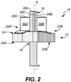
- FIG. 2 is a side view of a non-limiting example embodiment of a line-of-sight coating fixture 10.
- fixture 10 includes support structure 12, platter 14, spindle 16, shadow structure 18, compartments 20A, 20B, 20C, and workpieces 50A, 50B, 50C (example workpiece shown in FIG. 3 ).
- Spindle 16 retains support structure 12 and includes hole 24 disposed through a center of support structure 12 for rotating workpieces 50A, 50B, 50C thereabout.
- shadow structure 18 disposed about spindle 16, inward of the periphery.
- shadow structure 18 includes three respective shadow bars 26A, 26B, and 26C, each adapted to shield a portion of workpieces 50A, 50B, 50C from a line-of-sight coating or other stream (shown in FIG. 4 ).
- Each compartment 20A, 20B, 20C has a respective opening 30A, 30B, 30C on the periphery of support structure 12 below platter 14.
- compartments 20A, 20B, 20C are each adapted to receive and secure a base of respective workpieces 50A, 50B, 50C such that a body of each workpiece to be coated extends above platter 14 and is disposed about periphery of support structure 12.
- One or more of compartments 20A, 20B, 20C can optionally be an enclosure having one or more hinged doors 32A, 32B, 32C to fully shield the base of each workpiece.
- one or more of workpieces 50A, 50B, 50C can include a plurality of rotor blades, an example of which is seen in FIG. 3 .
- example rotor blade 50 includes, inter alia , airfoil 52, root 54, and platform 56.
- Other elements of blade 50 will be described with respect to FIGS. 3 and 4 as they relate to the coating apparatus and method.
- each compartment 20A, 20B, 20C is adapted to receive and secure root 54 such that airfoil portion 52, to be coated, is disposed about the periphery of support structure 12 and extends above platter 14.
- upper surface of platter 14 can be shaped to conform to platform(s) 56 of each of the rotor blades 50, such that upper surface 60 of platform 56 is exposed in the same manner of airfoil 52, while a lower surface 62 of platform 56 is shielded in the manner of root 52.
- compartments 20A, 20B, 20C can be shaped and adapted to conform to the base or root of each workpiece.
- root 54 is of a dovetail type with multiple lobes 66 of decreasing dimension.
- inside surfaces of e.g., compartment 20A can be provided with corresponding lobes (examples shown in FIGS. 5 and 6 ) to closely receive and securely retain the blade.
- a workpiece may have a single lobe, and as such these surfaces can conform accordingly.
- This optional adjustment to compartments 20A, 20B, 20C can be done on either a temporary or permanent basis.
- this disclosure illustrates (in FIGS. 5 and 6 ) two example pairs of removable inserts adapted to conform to the compartment and to two common types of roots for such workpieces. It will be appreciated that shrouds or other mounting structures can be made.
- the plurality of shadow bars 26A, 26B, 26C include walls defining a recess for receiving parts of the airfoil that are not to be coated.
- these recesses separately cover each trailing edge 68 of the plurality of airfoils 52.
- the recesses defined by the plurality of shadow bars also cover a portion of the pressure surface 76 adjacent to the trailing edge 68. This may be, for example, to cover windows, outlets, and or cooling slots 80 in trailing edge 68 and prevent coating material from infiltrating the interior of airfoil 52.
- FIG. 4 shows a line-of-sight coating apparatus 100 in which multiple fixtures can be used.
- apparatus 100 includes coating chamber 102 defined by chamber walls 104, vacuum / environmental port(s) 106, and at least one line-of-sight coating source 108 disposed along at least one wall 104.
- Source 108 which can include an EB-PVD coating source, is directed toward a plurality of fixtures 110A, 110B, 110C, at least one of which includes an embodiment of the above described fixture 10.
- fixtures 110A, 110B, 110C are arranged linearly and/or longitudinally opposed to coating source 108, selectively exposing surfaces of workpieces 150 to be coated.
- compartments 120 are operative to shield at least the base of each workpiece 150 from the line-of-sight coating material.
- workpieces 150 can include a plurality of rotor blades, so that compartments 120 each include a wall or walls adapted to receive and secure a root portion of a rotor blade such that a platform portion and an airfoil portion extend above the platform in a first orientation.
- An upper surface of the blade platform is exposed to the line-of-sight coating source and a lower surface of the platform is shielded from the line-of-sight coating source, and the plurality of shadow bars 126 cover each trailing edge and a portion (e.g., windows, outlets, and/or slots) of the pressure surface adjacent to the trailing edge of the plurality of airfoils.
- the arrangement shown in FIG. 4 is but one example of increasing coating throughput using the disclosed subject matter. Since the multi-piece fixtures shown herein are larger than a single-piece fixture known in the art, fewer multi-piece fixtures can fit into a coating chamber of a given size. However, the example shown still results in increased throughput, as three of the example three-piece fixtures can fit into a chamber previously known to hold five single-piece fixtures. This is a throughput increase of about 80%.
- FIG. 5 shows a removable insert 200 for one or more compartments 20, and includes a first insert piece 202 and a second insert piece 204 adapted to conform to first and second sides of a dovetail (multi-lobe) root.
- outer side walls 206, 208 of respective insert pieces 202, 204 are generally straight, while inner side walls 210, 212 define multiple lobes 214 corresponding to the negative surfaces of root 54 in blade 50.
- These inserts 202, 204 are inserted into compartment 20 as shown (in FIGS. 1 and 2 ) so that the blade is held upright for airfoil coating.
- FIG. 6 shows a removable insert 250 for one or more compartments 20, and includes a first insert piece 252 and a second insert piece 254 adapted to conform to first and second sides of a single-lobe root.
- outer side walls 256, 258 are generally straight to conform to compartment 20, and inner side walls have a single lobe 260 corresponding to the neck of blade 50 (between airfoil 52 and root lobe 56).
- these are inserted into compartment 20 as shown so that the blade is held upright for airfoil coating.
- these example inserts can be adapted for blades having roots arranged transverse to the blade chord, rather than collinear.
- a base of a workpiece is secured to a support structure including a plurality of compartments disposed below a platter.
- Each compartment has an opening on a periphery of the support structure for receiving each workpiece base, such that a body of each workpiece to be coated is disposed about a periphery of the support structure and extends above the platter.
- the workpieces are rotated about a spindle disposed through a center of the platter / support structure. A portion of each workpiece is shielded from one or more streams of line-of-sight coating material via a shadow structure disposed about the spindle.
- the plurality of workpieces can include one or more rotor blades, and as such, each compartment can be adapted to receive and secure a root of each rotor blade workpiece such that an airfoil portion of each rotor blade workpiece to be coated is disposed about a periphery of the support structure and extends above the platter.
- the platter can be shaped to conform to a platform of each of the plurality of rotor blades, such that an upper surface of the platform is exposed and a lower surface of the platform is shielded.
- An embodiment of a line-of-sight coating fixture includes a support structure, a spindle, and a shadow structure.
- the support structure includes a plurality of compartments disposed below a platter, each compartment having an opening on a periphery of the support structure. Each compartment is adapted to receive and secure a base of a workpiece such that a body of each workpiece to be coated is disposed about a periphery of the support structure and extends above the platter.
- the spindle is disposed through a center of the platter or support structure for rotating the workpieces thereabout.
- the shadow structure is disposed about the spindle, inside of the periphery, the shadow structure sized and adapted to shield a portion of each workpiece from line-of-sight coating material.
- a line-of-sight coating fixture includes a support structure including a plurality of compartments disposed below a platter, each compartment having an opening on a periphery of the support structure, and each compartment adapted to receive and secure a base of a workpiece such that a body of each workpiece to be coated is disposed about a periphery of the support structure and extends above the platter; a spindle disposed through a center of the platter or support structure for rotating the workpieces thereabout; and a shadow structure disposed about the spindle, inside of the periphery, the shadow structure sized and adapted to shield a portion of each workpiece from line-of-sight coating material.
- compartment is defined by an enclosure including at least one hinged door.
- each compartment is adapted to receive and secure a root of a workpiece such that an airfoil portion of each workpiece to be coated is disposed about a periphery of the support structure and extends above the platter.
- a further embodiment of any of the foregoing fixtures wherein the platter is shaped to conform to a platform of each of the plurality of rotor blades, such that an upper surface of the platform is exposed and a lower surface of the platform is shielded.
- a further embodiment of any of the foregoing fixtures further comprising at least one removable insert adapted to conform to the root of each workpiece.
- the at least one removable insert includes a first insert and a second insert adapted to conform to first and second sides of a dovetail root.
- a further embodiment of any of the foregoing fixtures wherein a span of the plurality of airfoils are aligned with a rotational axis of the fixture / spindle.
- the shadow structure includes a plurality of shadow bars including a plurality of shadow walls defining a recess for separately covering each trailing edge of the plurality of airfoils.
- a line-of-sight coating apparatus including a coating chamber defined by at least one wall and a line-of-sight coating source disposed along the at least one wall and directed toward a plurality of fixtures according to an embodiment of any of the foregoing fixtures.
- compartments are operative to shield at least the base of each workpiece from the line-of-sight coating material.
- the coating source includes an EB-PVD coating source.
- the plurality of workpieces include a plurality of rotor blades
- the plurality of compartments each include at least one removable insert adapted to receive and secure a root portion of a rotor blade such that a platform portion and an airfoil portion extend above the platform in a first orientation.
- a further embodiment of any of the foregoing apparatus wherein the platter is shaped to conform to a platform contour of each of the plurality of rotor blades, such that an upper surface of the platform is exposed to the line-of-sight coating source and a lower surface of the platform is shielded from the line-of-sight coating source.
- the shadow structure includes a plurality of shadow bars including at least one wall defining a recess for separately covering each trailing edge and a window or outlet portion of the pressure surface adjacent to the trailing edge of the plurality of airfoils.
- a method of line-of-sight coating includes securing a base of a workpiece to a support structure including a plurality of compartments disposed below a platter. Each compartment has an opening on a periphery of the support structure for receiving each workpiece base, such that a body of each workpiece to be coated is disposed about a periphery of the support structure and extends above the platter.
- the workpieces are rotated about a spindle disposed through a center of the platter or support structure. A portion of each workpiece is shielded from a stream of line-of-sight coating material via a shadow structure disposed about the spindle, inside of the periphery.
- a method includes securing a base of a workpiece to a support structure including a plurality of compartments disposed below a platter, each compartment having an opening on a periphery of the support structure for receiving each workpiece base, such that a body of each workpiece to be coated is disposed about a periphery of the support structure and extends above the platter; rotating the workpieces about a spindle disposed through a center of the platter or support structure; and shielding a portion of each workpiece from a stream of line-of-sight coating material via a shadow structure disposed about the spindle, inside of the periphery.
- the plurality of workpieces include a plurality of rotor blades; and wherein each compartment is adapted to receive and secure a root of each rotor blade workpiece such that an airfoil portion of each rotor blade workpiece to be coated is disposed about a periphery of the support structure and extends above the platter.
- the platter is shaped to conform to a platform of each of the plurality of rotor blades, such that an upper surface of the platform is exposed and a lower surface of the platform is shielded.
Landscapes
- Chemical & Material Sciences (AREA)
- Engineering & Computer Science (AREA)
- Mechanical Engineering (AREA)
- Chemical Kinetics & Catalysis (AREA)
- Materials Engineering (AREA)
- Metallurgy (AREA)
- Organic Chemistry (AREA)
- Analytical Chemistry (AREA)
- General Engineering & Computer Science (AREA)
- Physical Vapour Deposition (AREA)
- Application Of Or Painting With Fluid Materials (AREA)
- Coating Apparatus (AREA)
Abstract
Description
- The disclosure is related generally to fixtures for line-of-sight coating apparatus, and more specifically to fixtures for optimizing throughput of line-of-sight coating apparatus.
- Many vapor coating, and other line-of-sight coating fixtures, in particular for airfoils, are limited to hold a single part per fixture. Attempts to increase the number of workpieces on a single fixture often lead to uneven coating application, either due to inadvertent blocking of the coating stream by portions of the fixture, or by uneven heating throughout the chamber, leading to differences in adhesion and microstructure of the coating.
- As such, conventional approaches utilize multiple fixtures, each with a single workpiece, fixed to a rake or other device disposed at the base of the chamber in order to somewhat increase efficiency and throughput for a batch coating process. However, each coating machine is limited in how many fixtures it can hold, and the cost of additional machines can be cost-prohibitive when trying to ramp up production from a product introduction to sustained long-term operation.
- An embodiment of a line-of-sight coating fixture includes a support structure, a spindle, and a shadow structure. The support structure includes a plurality of compartments disposed below a platter, each compartment having an opening on a periphery of the support structure. Each compartment is adapted to receive and secure a base of a workpiece such that a body of each workpiece to be coated is disposed about a periphery of the support structure and extends above the platter. The spindle is disposed through a center of the platter or support structure for rotating the workpieces thereabout. The shadow structure is disposed about the spindle, inside of the periphery, the shadow structure sized and adapted to shield a portion of each workpiece from line-of-sight coating material.
- A method of line-of-sight coating includes securing a base of a workpiece to a support structure including a plurality of compartments disposed below a platter. Each compartment has an opening on a periphery of the support structure for receiving each workpiece base, such that a body of each workpiece to be coated is disposed about a periphery of the support structure and extends above the platter. The workpieces are rotated about a spindle disposed through a center of the platter or support structure. A portion of each workpiece is shielded from a stream of line-of-sight coating material via a shadow structure disposed about the spindle, inside of the periphery.
-
-
FIG. 1 is a top view of a non-limiting example embodiment of a line-of-sight coating fixture according to the disclosure. -
FIG. 2 is a side view of the example coating fixture ofFIG. 1 and the example workpiece ofFIG. 3 . -
FIG. 3 is a non-limiting example workpiece for which the example coating fixture ofFIGS. 1 and2 is adapted. -
FIG. 4 is an example line-of-sight coating apparatus with multiple instances of the example embodiment disposed therein. -
FIG. 5 is an example insert for a dovetail root. -
FIG. 6 is an example insert for a single-lobe root. -
FIG. 1 is a top view, andFIG. 2 is a side view of a non-limiting example embodiment of a line-of-sight coating fixture 10. Referring first toFIG. 1 ,fixture 10 includessupport structure 12,platter 14,spindle 16,shadow structure 18,compartments workpieces FIG. 3 ).Support structure 12, in this example, includes threecoating positions workpieces support structure 12 and includeshole 24 disposed through a center ofsupport structure 12 for rotatingworkpieces - Also visible in
FIG. 1 isshadow structure 18 disposed aboutspindle 16, inward of the periphery. In this example having threecoating positions shadow structure 18 includes threerespective shadow bars workpieces FIG. 4 ). Eachcompartment support structure 12 belowplatter 14. - Moving to
FIG. 2 (but still partially visible inFIG. 1 ),compartments respective workpieces platter 14 and is disposed about periphery ofsupport structure 12. One or more ofcompartments doors - As already seen from
FIGS. 1 and2 , one or more ofworkpieces FIG. 3 . Referring momentarily toFIG. 3 ,example rotor blade 50 includes, inter alia,airfoil 52,root 54, andplatform 56. Other elements ofblade 50 will be described with respect toFIGS. 3 and4 as they relate to the coating apparatus and method. - Returning to
FIGS. 1 and2 , for purposes of coating a rotor blade, eachcompartment root 54 such thatairfoil portion 52, to be coated, is disposed about the periphery ofsupport structure 12 and extends aboveplatter 14. In certain embodiments, upper surface ofplatter 14 can be shaped to conform to platform(s) 56 of each of therotor blades 50, such thatupper surface 60 ofplatform 56 is exposed in the same manner ofairfoil 52, while alower surface 62 ofplatform 56 is shielded in the manner ofroot 52. - For flexibility in coating different types of workpieces on the same equipment, the inside surfaces of one or more of
compartments FIG. 3 ,root 54 is of a dovetail type with multiple lobes 66 of decreasing dimension. As such, inside surfaces of e.g.,compartment 20A can be provided with corresponding lobes (examples shown inFIGS. 5 and 6 ) to closely receive and securely retain the blade. Alternately, a workpiece may have a single lobe, and as such these surfaces can conform accordingly. This optional adjustment tocompartments FIGS. 5 and 6 ) two example pairs of removable inserts adapted to conform to the compartment and to two common types of roots for such workpieces. It will be appreciated that shrouds or other mounting structures can be made. - This arrangement also allows a span of each of the plurality of
airfoils 52 to be aligned with a rotational axis A of the fixture / spindle. Further, in this example, the plurality ofshadow bars FIGS. 1 and2 , these recesses separately cover eachtrailing edge 68 of the plurality ofairfoils 52. The recesses defined by the plurality of shadow bars also cover a portion of thepressure surface 76 adjacent to thetrailing edge 68. This may be, for example, to cover windows, outlets, and orcooling slots 80 intrailing edge 68 and prevent coating material from infiltrating the interior ofairfoil 52. -
FIG. 4 shows a line-of-sight coating apparatus 100 in which multiple fixtures can be used. Generally,apparatus 100 includescoating chamber 102 defined bychamber walls 104, vacuum / environmental port(s) 106, and at least one line-of-sight coating source 108 disposed along at least onewall 104.Source 108, which can include an EB-PVD coating source, is directed toward a plurality offixtures fixture 10. - As shown in
FIG. 4 ,fixtures coating source 108, selectively exposing surfaces ofworkpieces 150 to be coated. As described with respect toFIGS. 1 and2 ,compartments 120 are operative to shield at least the base of eachworkpiece 150 from the line-of-sight coating material. As above,workpieces 150 can include a plurality of rotor blades, so thatcompartments 120 each include a wall or walls adapted to receive and secure a root portion of a rotor blade such that a platform portion and an airfoil portion extend above the platform in a first orientation. An upper surface of the blade platform is exposed to the line-of-sight coating source and a lower surface of the platform is shielded from the line-of-sight coating source, and the plurality ofshadow bars 126 cover each trailing edge and a portion (e.g., windows, outlets, and/or slots) of the pressure surface adjacent to the trailing edge of the plurality of airfoils. - The arrangement shown in
FIG. 4 is but one example of increasing coating throughput using the disclosed subject matter. Since the multi-piece fixtures shown herein are larger than a single-piece fixture known in the art, fewer multi-piece fixtures can fit into a coating chamber of a given size. However, the example shown still results in increased throughput, as three of the example three-piece fixtures can fit into a chamber previously known to hold five single-piece fixtures. This is a throughput increase of about 80%. - This not only increases the total number of parts which are coated per charge in the machine, but also created a more stable temperature gradient due to the added, consistent thermal mass. This even temperature leads to a more consistent coating from part to part, even when located on different fixtures.
-
FIG. 5 shows aremovable insert 200 for one or more compartments 20, and includes afirst insert piece 202 and asecond insert piece 204 adapted to conform to first and second sides of a dovetail (multi-lobe) root. Here,outer side walls respective insert pieces inner side walls multiple lobes 214 corresponding to the negative surfaces ofroot 54 inblade 50. Theseinserts FIGS. 1 and2 ) so that the blade is held upright for airfoil coating. -
FIG. 6 shows aremovable insert 250 for one or more compartments 20, and includes afirst insert piece 252 and asecond insert piece 254 adapted to conform to first and second sides of a single-lobe root. As inFIG. 5 ,outer side walls single lobe 260 corresponding to the neck of blade 50 (betweenairfoil 52 and root lobe 56). As withFIG. 5 , these are inserted into compartment 20 as shown so that the blade is held upright for airfoil coating. In either case, however, these example inserts can be adapted for blades having roots arranged transverse to the blade chord, rather than collinear. - Summarizing a method of line-of-sight coating using the apparatus disclosed herein, a base of a workpiece is secured to a support structure including a plurality of compartments disposed below a platter. Each compartment has an opening on a periphery of the support structure for receiving each workpiece base, such that a body of each workpiece to be coated is disposed about a periphery of the support structure and extends above the platter. The workpieces are rotated about a spindle disposed through a center of the platter / support structure. A portion of each workpiece is shielded from one or more streams of line-of-sight coating material via a shadow structure disposed about the spindle.
- As previously described, the plurality of workpieces can include one or more rotor blades, and as such, each compartment can be adapted to receive and secure a root of each rotor blade workpiece such that an airfoil portion of each rotor blade workpiece to be coated is disposed about a periphery of the support structure and extends above the platter. The platter can be shaped to conform to a platform of each of the plurality of rotor blades, such that an upper surface of the platform is exposed and a lower surface of the platform is shielded.
- The following are non-exclusive descriptions of possible embodiments of the present disclosure.
- An embodiment of a line-of-sight coating fixture includes a support structure, a spindle, and a shadow structure. The support structure includes a plurality of compartments disposed below a platter, each compartment having an opening on a periphery of the support structure. Each compartment is adapted to receive and secure a base of a workpiece such that a body of each workpiece to be coated is disposed about a periphery of the support structure and extends above the platter. The spindle is disposed through a center of the platter or support structure for rotating the workpieces thereabout. The shadow structure is disposed about the spindle, inside of the periphery, the shadow structure sized and adapted to shield a portion of each workpiece from line-of-sight coating material.
- The fixture of the preceding paragraph can optionally include, additionally and/or alternatively, any one or more of the following features, configurations and/or additional components:
A line-of-sight coating fixture, according to an exemplary embodiment of this disclosure, among other possible things includes a support structure including a plurality of compartments disposed below a platter, each compartment having an opening on a periphery of the support structure, and each compartment adapted to receive and secure a base of a workpiece such that a body of each workpiece to be coated is disposed about a periphery of the support structure and extends above the platter; a spindle disposed through a center of the platter or support structure for rotating the workpieces thereabout; and a shadow structure disposed about the spindle, inside of the periphery, the shadow structure sized and adapted to shield a portion of each workpiece from line-of-sight coating material. - A further embodiment of the foregoing fixture, wherein the compartment is defined by an enclosure including at least one hinged door.
- A further embodiment of any of the foregoing fixtures, wherein the plurality of workpieces include a plurality of rotor blades.
- A further embodiment of any of the foregoing fixtures, wherein each compartment is adapted to receive and secure a root of a workpiece such that an airfoil portion of each workpiece to be coated is disposed about a periphery of the support structure and extends above the platter.
- A further embodiment of any of the foregoing fixtures, wherein the platter is shaped to conform to a platform of each of the plurality of rotor blades, such that an upper surface of the platform is exposed and a lower surface of the platform is shielded.
- A further embodiment of any of the foregoing fixtures, further comprising at least one removable insert adapted to conform to the root of each workpiece.
- A further embodiment of any of the foregoing fixtures, wherein the at least one removable insert includes a first insert and a second insert adapted to conform to first and second sides of a dovetail root.
- A further embodiment of any of the foregoing fixtures, wherein a span of the plurality of airfoils are aligned with a rotational axis of the fixture / spindle.
- A further embodiment of any of the foregoing fixtures, wherein the shadow structure includes a plurality of shadow bars including a plurality of shadow walls defining a recess for separately covering each trailing edge of the plurality of airfoils.
- A further embodiment of any of the foregoing fixtures, wherein the recesses defined by the plurality of shadow bars also cover a window or outlet portion of the pressure surface adjacent to the trailing edge.
- A line-of-sight coating apparatus including a coating chamber defined by at least one wall and a line-of-sight coating source disposed along the at least one wall and directed toward a plurality of fixtures according to an embodiment of any of the foregoing fixtures.
- A further embodiment of the foregoing apparatus, wherein the plurality of fixtures are arranged linearly or longitudinally opposed to the coating source.
- A further embodiment of any of the foregoing apparatus, wherein the compartments are operative to shield at least the base of each workpiece from the line-of-sight coating material.
- A further embodiment of any of the foregoing apparatus, wherein the coating source includes an EB-PVD coating source.
- A further embodiment of any of the foregoing apparatus, wherein the plurality of workpieces include a plurality of rotor blades, and wherein the plurality of compartments each include at least one removable insert adapted to receive and secure a root portion of a rotor blade such that a platform portion and an airfoil portion extend above the platform in a first orientation.
- A further embodiment of any of the foregoing apparatus, wherein the platter is shaped to conform to a platform contour of each of the plurality of rotor blades, such that an upper surface of the platform is exposed to the line-of-sight coating source and a lower surface of the platform is shielded from the line-of-sight coating source.
- A further embodiment of any of the foregoing apparatus, wherein the shadow structure includes a plurality of shadow bars including at least one wall defining a recess for separately covering each trailing edge and a window or outlet portion of the pressure surface adjacent to the trailing edge of the plurality of airfoils.
- A method of line-of-sight coating includes securing a base of a workpiece to a support structure including a plurality of compartments disposed below a platter. Each compartment has an opening on a periphery of the support structure for receiving each workpiece base, such that a body of each workpiece to be coated is disposed about a periphery of the support structure and extends above the platter. The workpieces are rotated about a spindle disposed through a center of the platter or support structure. A portion of each workpiece is shielded from a stream of line-of-sight coating material via a shadow structure disposed about the spindle, inside of the periphery.
- The method of the preceding paragraph can optionally include, additionally and/or alternatively, any one or more of the following features, configurations and/or additional components:
A method according to an exemplary embodiment of this disclosure, among other possible things includes securing a base of a workpiece to a support structure including a plurality of compartments disposed below a platter, each compartment having an opening on a periphery of the support structure for receiving each workpiece base, such that a body of each workpiece to be coated is disposed about a periphery of the support structure and extends above the platter; rotating the workpieces about a spindle disposed through a center of the platter or support structure; and shielding a portion of each workpiece from a stream of line-of-sight coating material via a shadow structure disposed about the spindle, inside of the periphery. - A further embodiment of the foregoing method, wherein the plurality of workpieces include a plurality of rotor blades; and wherein each compartment is adapted to receive and secure a root of each rotor blade workpiece such that an airfoil portion of each rotor blade workpiece to be coated is disposed about a periphery of the support structure and extends above the platter.
- A further embodiment of any of the foregoing methods, wherein the platter is shaped to conform to a platform of each of the plurality of rotor blades, such that an upper surface of the platform is exposed and a lower surface of the platform is shielded.
- While the invention has been described with reference to an exemplary embodiment(s), it will be understood by those skilled in the art that various changes may be made and equivalents may be substituted for elements thereof without departing from the scope of the invention. In addition, many modifications may be made to adapt a particular situation or material to the teachings of the invention without departing from the essential scope thereof. Therefore, it is intended that the invention not be limited to the particular embodiment(s) disclosed, but that the invention will include all embodiments falling within the scope of the appended claims.
Claims (15)
- A line-of-sight coating fixture (10, 110A-C) comprising:a support structure (12) including a plurality of compartments (20A-C) disposed below a platter (14), each compartment (20A-C) having an opening (30A-C) on a periphery of the support structure (12), and each compartment (20A-C) adapted to receive and secure a base of a workpiece (50A-C) such that a body of each workpiece (50A-C) to be coated is disposed about a periphery of the support structure (12) and extends above the platter (14);a spindle (16) disposed through a center of the platter (14) or support structure (12) for rotating the workpieces (50A-C) thereabout; anda shadow structure (18) disposed about the spindle (16), inside of the periphery, the shadow structure (18) sized and adapted to shield a portion of each workpiece (50A-C) from line-of-sight coating material.
- The fixture (10, 110A-C) of claim 1, wherein the compartment (20A-C) is defined by an enclosure including at least one hinged door (32A-C).
- The fixture (10, 110A-C) of claim 1 or 2, wherein the plurality of workpieces (50A-C) include a plurality of rotor blades (50).
- The fixture (10, 110A-C) of claim 3, wherein each compartment (20A-C) is adapted to receive and secure a root (54) of a workpiece (50A-C) such that an airfoil portion (52) of each workpiece (50A-C) to be coated is disposed about a periphery of the support structure (12) and extends above the platter (14).
- The fixture (10, 110A-C) of claim 4, wherein the platter (14) is shaped to conform to a platform (56) of each of the plurality of rotor blades (50), such that an upper surface (60) of the platform (56) is exposed and a lower surface (62) of the platform (56) is shielded.
- The fixture (10, 110A-C) of claim 4 or 5, further comprising at least one removable insert (200; 250) adapted to conform to the root (54) of each workpiece (50A-C), wherein, optionally, the at least one removable insert (200) includes a first insert (202) and a second insert (204) adapted to conform to first and second sides of a dovetail root (54).
- The fixture (10, 110A-C) of any of claims 3 to 6, wherein a span of the plurality of airfoils (52) are aligned with a rotational axis (A) of the fixture (10) or spindle (16).
- The fixture (10, 110A-C) of any of claims 3 to 7, wherein the shadow structure (18) includes a plurality of shadow bars (26A-C) including a plurality of shadow walls defining a recess for separately covering each trailing edge (68) of the plurality of airfoils (52), and wherein, optionally, the recesses defined by the plurality of shadow bars (26A-C) also cover a window or outlet portion (80) of a pressure surface (76) adjacent to the trailing edge (68).
- A line-of-sight coating apparatus (100) comprising:a coating chamber (102) defined by at least one wall (104);a line-of-sight coating source (108) disposed along the at least one wall (104) and directed toward a plurality of fixtures (10, 110A-C) according to any preceding claim.
- The apparatus (100) of claim 9, wherein:the plurality of fixtures (10, 110A-C) are arranged linearly or longitudinally opposed to the coating source (108); and/orthe coating source (108) includes an EB-PVD coating source.
- The apparatus (100) of claim 9 or 10, wherein the compartments (20A-C) are operative to shield at least the base of each workpiece (50A-C) from the line-of-sight coating material.
- The apparatus (100) of claims 3 and 9, 10 or 11, wherein the plurality of compartments (20A-C) each include at least one removable insert (200; 250) adapted to receive and secure a root portion (54) of a rotor blade (50) such that a platform portion (56) and an airfoil portion (52) extend above the platform (56) in a first orientation.
- A method of line-of-sight coating comprising:securing a base of a workpiece (50A-C) to a support structure (12) including a plurality of compartments (20A-C) disposed below a platter (14), each compartment (20A-C) having an opening (30A-C) on a periphery of the support structure (12) for receiving each workpiece base, such that a body of each workpiece (50A-C) to be coated is disposed about a periphery of the support structure (12) and extends above the platter (14);rotating the workpieces (50A-C) about a spindle (16) disposed through a center of the platter (14) or support structure (12); andshielding a portion of each workpiece (50A-C) from a stream of line-of-sight coating material via a shadow structure (18) disposed about the spindle (16), inside of the periphery.
- The method of claim 13, wherein the plurality of workpieces (50A-C) include a plurality of rotor blades (50), and wherein each compartment (20A-C) is adapted to receive and secure a root (54) of each rotor blade workpiece (50A-C) such that an airfoil portion (52) of each rotor blade workpiece (50A-C) to be coated is disposed about a periphery of the support structure (12) and extends above the platter (14).
- The method of claim 14, wherein the platter (14) is shaped to conform to a platform (56) of each of the plurality of rotor blades (50), such that an upper surface (60) of the platform (56) is exposed and a lower surface (62) of the platform (56) is shielded.
Applications Claiming Priority (1)
| Application Number | Priority Date | Filing Date | Title |
|---|---|---|---|
| US15/852,558 US20190194799A1 (en) | 2017-12-22 | 2017-12-22 | Line-of-sight coating fixture and apparatus |
Publications (2)
| Publication Number | Publication Date |
|---|---|
| EP3502305A1 true EP3502305A1 (en) | 2019-06-26 |
| EP3502305B1 EP3502305B1 (en) | 2022-06-01 |
Family
ID=65010427
Family Applications (1)
| Application Number | Title | Priority Date | Filing Date |
|---|---|---|---|
| EP18214948.4A Active EP3502305B1 (en) | 2017-12-22 | 2018-12-20 | Line-of-sight coating fixture and apparatus |
Country Status (2)
| Country | Link |
|---|---|
| US (2) | US20190194799A1 (en) |
| EP (1) | EP3502305B1 (en) |
Citations (2)
| Publication number | Priority date | Publication date | Assignee | Title |
|---|---|---|---|---|
| US20130149450A1 (en) * | 2011-12-08 | 2013-06-13 | Albert Feuerstein | Tooling fixture assembly for use in a coating operation |
| US9381537B2 (en) * | 2011-12-08 | 2016-07-05 | Praxair Technology, Inc. | Multifunction tooling fixture assembly for use in a coating related operations |
Family Cites Families (39)
| Publication number | Priority date | Publication date | Assignee | Title |
|---|---|---|---|---|
| US4108107A (en) | 1976-04-01 | 1978-08-22 | Airco, Inc. | Rotatable substrate holder for use in vacuum |
| US4271005A (en) | 1979-12-03 | 1981-06-02 | United Technologies Corporation | Workpiece support apparatus for use with cathode sputtering devices |
| US4485759A (en) * | 1983-01-19 | 1984-12-04 | Multi-Arc Vacuum Systems Inc. | Planetary substrate support apparatus for vapor vacuum deposition coating |
| US4704298A (en) | 1986-07-31 | 1987-11-03 | The Research Foundation Of State University Of New York | Coating spherical objects |
| US5251409A (en) | 1992-06-15 | 1993-10-12 | Outboard Marine Corporation | Method of drag finishing a housing |
| US6083322A (en) | 1997-03-06 | 2000-07-04 | United Technologies Corporation | Modular coating fixture |
| US5792267A (en) * | 1997-05-16 | 1998-08-11 | United Technologies Corporation | Coating fixture for a turbine engine blade |
| US5813118A (en) | 1997-06-23 | 1998-09-29 | General Electric Company | Method for repairing an air cooled turbine engine airfoil |
| US5902471A (en) | 1997-10-01 | 1999-05-11 | United Technologies Corporation | Process for selectively electroplating an airfoil |
| US6037004A (en) | 1997-12-19 | 2000-03-14 | United Technologies Corporation | Shield and method for protecting an airfoil surface |
| US5997947A (en) | 1998-04-29 | 1999-12-07 | United Technologies Corporation | Rotisserie fixture for coating airfoils |
| US6224673B1 (en) | 1999-08-11 | 2001-05-01 | General Electric Company | Apparatus for masking turbine components during vapor phase diffusion coating |
| US6419753B1 (en) | 2000-04-07 | 2002-07-16 | General Electric Company | Apparatus and method for masking multiple turbine components |
| FR2827311B1 (en) | 2001-07-12 | 2003-09-19 | Snecma Moteurs | PROCESS FOR LOCAL REPAIR OF PARTS COATED WITH A THERMAL BARRIER |
| US6863927B2 (en) | 2002-09-27 | 2005-03-08 | General Electric Aviation Service Operation Ptd. Ltd. | Method for vapor phase aluminiding of a gas turbine blade partially masked with a masking enclosure |
| US7008553B2 (en) | 2003-01-09 | 2006-03-07 | General Electric Company | Method for removing aluminide coating from metal substrate and turbine engine part so treated |
| US8349086B2 (en) | 2004-07-30 | 2013-01-08 | United Technologies Corporation | Non-stick masking fixtures and methods of preparing same |
| US7837843B2 (en) | 2005-07-12 | 2010-11-23 | Praxair S.T. Technology, Inc. | Fixture for use in a coating operation |
| DE502007001920D1 (en) | 2006-05-26 | 2009-12-17 | Siemens Ag | RAY DEVICE |
| US7831098B2 (en) | 2006-11-07 | 2010-11-09 | Recognition Robotics | System and method for visual searching of objects using lines |
| SG154344A1 (en) | 2008-01-09 | 2009-08-28 | United Technologies Corp | Airfoil mask, airfoil and mask system, and masking method for edge profile finishing |
| EP2100984A1 (en) | 2008-03-14 | 2009-09-16 | Siemens Aktiengesellschaft | Method for masking cooling holes and device for using in a masking process for masking cooling holes |
| US8211234B2 (en) | 2008-09-02 | 2012-07-03 | United Technologies Corporation | Coater platter homing tool |
| US20110052406A1 (en) * | 2009-08-25 | 2011-03-03 | General Electric Company | Airfoil and process for depositing an erosion-resistant coating on the airfoil |
| DE102009060649A1 (en) | 2009-12-22 | 2011-06-30 | EISENMANN Anlagenbau GmbH & Co. KG, 71032 | Plant for surface treatment of objects |
| DE102010017895A1 (en) | 2010-04-21 | 2011-10-27 | Ald Vacuum Technologies Gmbh | Device for coating substrates according to the EB / PVD method |
| DE102010037401A1 (en) | 2010-09-08 | 2012-03-08 | Ctp Gmbh | application unit |
| TW201213587A (en) | 2010-09-21 | 2012-04-01 | Hon Hai Prec Ind Co Ltd | Conveying mechanism and deposition device with same |
| SG10201601693VA (en) * | 2011-03-17 | 2016-04-28 | Sulzer Metco Ag | Component manipulator for the dynamic positioning of a substrate, coating method, as well as use of a component manipulator |
| DE102011108771B3 (en) | 2011-07-28 | 2012-09-27 | Mtu Aero Engines Gmbh | Process for producing a localized diffusion layer and reactor therefor |
| US8720369B2 (en) * | 2011-11-21 | 2014-05-13 | The Lost Boy Group, Llc | Masking system for coating aircraft components |
| EP2839053B1 (en) | 2012-04-16 | 2017-05-31 | The Timken Company | Method and table assembly for applying coatings to spherical components |
| US9279332B2 (en) | 2012-05-31 | 2016-03-08 | Solar Turbines Incorporated | Turbine damper |
| SG195417A1 (en) | 2012-06-01 | 2013-12-30 | Pratt & Whitney Services Pte Ltd | Polishing assembly and method for polishing |
| JP6547971B2 (en) | 2013-08-28 | 2019-07-24 | エムディーエス コーティング テクノロジーズ コーポレーションMds Coating Technologies Corp. | Airfoil covering and method of grinding airfoil |
| US9527097B2 (en) | 2013-11-05 | 2016-12-27 | Torrent Systems Llc | Spray coating system and method |
| US9861998B2 (en) | 2014-04-07 | 2018-01-09 | Oria Collapsibles, Llc | Assembly for coating an article incorporating robotic subassemblies utilizing articulating spray arms and carousel conveyor with inlet and outlet locations for the article |
| DE102015208783A1 (en) | 2015-05-12 | 2016-11-17 | MTU Aero Engines AG | Covering method for producing a combination of blade tip armor and erosion protection layer |
| US11225707B2 (en) | 2019-08-13 | 2022-01-18 | General Electric Company | Protective shields for improved coating of turbine component cooling features |
-
2017
- 2017-12-22 US US15/852,558 patent/US20190194799A1/en not_active Abandoned
-
2018
- 2018-12-20 EP EP18214948.4A patent/EP3502305B1/en active Active
-
2022
- 2022-02-10 US US17/668,591 patent/US11702732B2/en active Active
Patent Citations (2)
| Publication number | Priority date | Publication date | Assignee | Title |
|---|---|---|---|---|
| US20130149450A1 (en) * | 2011-12-08 | 2013-06-13 | Albert Feuerstein | Tooling fixture assembly for use in a coating operation |
| US9381537B2 (en) * | 2011-12-08 | 2016-07-05 | Praxair Technology, Inc. | Multifunction tooling fixture assembly for use in a coating related operations |
Also Published As
| Publication number | Publication date |
|---|---|
| EP3502305B1 (en) | 2022-06-01 |
| US11702732B2 (en) | 2023-07-18 |
| US20220162745A1 (en) | 2022-05-26 |
| US20190194799A1 (en) | 2019-06-27 |
Similar Documents
| Publication | Publication Date | Title |
|---|---|---|
| CA2614924A1 (en) | Fixture for use in a coating operation | |
| US20130180850A1 (en) | Magnetron sputtering apparatus | |
| EP2788525B1 (en) | Tooling fixture assembly for use in a coating operation | |
| RU2013152402A (en) | AXIAL TURBO MACHINE SHOVEL WITH PLATFORMS WITH ANGULAR PROFILE | |
| EP3502305B1 (en) | Line-of-sight coating fixture and apparatus | |
| US10072326B2 (en) | Versatile holder for treating the surface of rod-shaped substrates | |
| US8499597B2 (en) | Device and method for the surface peening of a component of a gas turbine | |
| RU2019141072A (en) | METHOD FOR IMPLEMENTING BLADE OF AIRCRAFT GAS TURBINE ENGINE BY MEANS OF ADDITIVE MANUFACTURING | |
| KR102761544B1 (en) | Device and method for selective vapor coating of substrates | |
| US10076816B2 (en) | Method and device for machining the blade tips of a compressor rotor of a gas turbine | |
| US20150368786A1 (en) | Metallic coating fixed stator tip treatment | |
| CN102733862A (en) | Locking device arrangement for rotating bladed stage | |
| CN106756818A (en) | A kind of protection device and method for turborotor variable-angle applying coating | |
| EP3060703B1 (en) | Method for creating airfoil leading and trailing edges | |
| KR200299383Y1 (en) | cutter of armature balancing machine | |
| CN114718658A (en) | Tool and method for controlling width of baffle ring installation groove | |
| BRPI0613524B1 (en) | ACCESSORY FOR USE IN A COATING OPERATION | |
| US20160222805A1 (en) | Turbine blade and gas turbine |
Legal Events
| Date | Code | Title | Description |
|---|---|---|---|
| PUAI | Public reference made under article 153(3) epc to a published international application that has entered the european phase |
Free format text: ORIGINAL CODE: 0009012 |
|
| STAA | Information on the status of an ep patent application or granted ep patent |
Free format text: STATUS: THE APPLICATION HAS BEEN PUBLISHED |
|
| AK | Designated contracting states |
Kind code of ref document: A1 Designated state(s): AL AT BE BG CH CY CZ DE DK EE ES FI FR GB GR HR HU IE IS IT LI LT LU LV MC MK MT NL NO PL PT RO RS SE SI SK SM TR |
|
| AX | Request for extension of the european patent |
Extension state: BA ME |
|
| STAA | Information on the status of an ep patent application or granted ep patent |
Free format text: STATUS: REQUEST FOR EXAMINATION WAS MADE |
|
| 17P | Request for examination filed |
Effective date: 20191219 |
|
| RBV | Designated contracting states (corrected) |
Designated state(s): AL AT BE BG CH CY CZ DE DK EE ES FI FR GB GR HR HU IE IS IT LI LT LU LV MC MK MT NL NO PL PT RO RS SE SI SK SM TR |
|
| RAP1 | Party data changed (applicant data changed or rights of an application transferred) |
Owner name: RAYTHEON TECHNOLOGIES CORPORATION |
|
| GRAP | Despatch of communication of intention to grant a patent |
Free format text: ORIGINAL CODE: EPIDOSNIGR1 |
|
| STAA | Information on the status of an ep patent application or granted ep patent |
Free format text: STATUS: GRANT OF PATENT IS INTENDED |
|
| RIC1 | Information provided on ipc code assigned before grant |
Ipc: H01J 37/32 20060101ALN20211202BHEP Ipc: B05C 15/00 20060101ALN20211202BHEP Ipc: B05B 13/02 20060101ALN20211202BHEP Ipc: H01J 37/20 20060101ALI20211202BHEP Ipc: F01D 25/28 20060101ALI20211202BHEP Ipc: B05C 13/02 20060101ALI20211202BHEP Ipc: C23C 14/50 20060101ALI20211202BHEP Ipc: C23C 14/04 20060101AFI20211202BHEP |
|
| INTG | Intention to grant announced |
Effective date: 20211220 |
|
| GRAS | Grant fee paid |
Free format text: ORIGINAL CODE: EPIDOSNIGR3 |
|
| GRAA | (expected) grant |
Free format text: ORIGINAL CODE: 0009210 |
|
| STAA | Information on the status of an ep patent application or granted ep patent |
Free format text: STATUS: THE PATENT HAS BEEN GRANTED |
|
| AK | Designated contracting states |
Kind code of ref document: B1 Designated state(s): AL AT BE BG CH CY CZ DE DK EE ES FI FR GB GR HR HU IE IS IT LI LT LU LV MC MK MT NL NO PL PT RO RS SE SI SK SM TR |
|
| REG | Reference to a national code |
Ref country code: GB Ref legal event code: FG4D |
|
| REG | Reference to a national code |
Ref country code: AT Ref legal event code: REF Ref document number: 1495420 Country of ref document: AT Kind code of ref document: T Effective date: 20220615 Ref country code: CH Ref legal event code: EP |
|
| REG | Reference to a national code |
Ref country code: IE Ref legal event code: FG4D |
|
| REG | Reference to a national code |
Ref country code: DE Ref legal event code: R096 Ref document number: 602018036150 Country of ref document: DE |
|
| REG | Reference to a national code |
Ref country code: LT Ref legal event code: MG9D |
|
| REG | Reference to a national code |
Ref country code: NL Ref legal event code: MP Effective date: 20220601 |
|
| PG25 | Lapsed in a contracting state [announced via postgrant information from national office to epo] |
Ref country code: SE Free format text: LAPSE BECAUSE OF FAILURE TO SUBMIT A TRANSLATION OF THE DESCRIPTION OR TO PAY THE FEE WITHIN THE PRESCRIBED TIME-LIMIT Effective date: 20220601 Ref country code: NO Free format text: LAPSE BECAUSE OF FAILURE TO SUBMIT A TRANSLATION OF THE DESCRIPTION OR TO PAY THE FEE WITHIN THE PRESCRIBED TIME-LIMIT Effective date: 20220901 Ref country code: LT Free format text: LAPSE BECAUSE OF FAILURE TO SUBMIT A TRANSLATION OF THE DESCRIPTION OR TO PAY THE FEE WITHIN THE PRESCRIBED TIME-LIMIT Effective date: 20220601 Ref country code: HR Free format text: LAPSE BECAUSE OF FAILURE TO SUBMIT A TRANSLATION OF THE DESCRIPTION OR TO PAY THE FEE WITHIN THE PRESCRIBED TIME-LIMIT Effective date: 20220601 Ref country code: GR Free format text: LAPSE BECAUSE OF FAILURE TO SUBMIT A TRANSLATION OF THE DESCRIPTION OR TO PAY THE FEE WITHIN THE PRESCRIBED TIME-LIMIT Effective date: 20220902 Ref country code: FI Free format text: LAPSE BECAUSE OF FAILURE TO SUBMIT A TRANSLATION OF THE DESCRIPTION OR TO PAY THE FEE WITHIN THE PRESCRIBED TIME-LIMIT Effective date: 20220601 Ref country code: ES Free format text: LAPSE BECAUSE OF FAILURE TO SUBMIT A TRANSLATION OF THE DESCRIPTION OR TO PAY THE FEE WITHIN THE PRESCRIBED TIME-LIMIT Effective date: 20220601 Ref country code: BG Free format text: LAPSE BECAUSE OF FAILURE TO SUBMIT A TRANSLATION OF THE DESCRIPTION OR TO PAY THE FEE WITHIN THE PRESCRIBED TIME-LIMIT Effective date: 20220901 |
|
| REG | Reference to a national code |
Ref country code: AT Ref legal event code: MK05 Ref document number: 1495420 Country of ref document: AT Kind code of ref document: T Effective date: 20220601 |
|
| PG25 | Lapsed in a contracting state [announced via postgrant information from national office to epo] |
Ref country code: RS Free format text: LAPSE BECAUSE OF FAILURE TO SUBMIT A TRANSLATION OF THE DESCRIPTION OR TO PAY THE FEE WITHIN THE PRESCRIBED TIME-LIMIT Effective date: 20220601 Ref country code: PL Free format text: LAPSE BECAUSE OF FAILURE TO SUBMIT A TRANSLATION OF THE DESCRIPTION OR TO PAY THE FEE WITHIN THE PRESCRIBED TIME-LIMIT Effective date: 20220601 Ref country code: LV Free format text: LAPSE BECAUSE OF FAILURE TO SUBMIT A TRANSLATION OF THE DESCRIPTION OR TO PAY THE FEE WITHIN THE PRESCRIBED TIME-LIMIT Effective date: 20220601 |
|
| PG25 | Lapsed in a contracting state [announced via postgrant information from national office to epo] |
Ref country code: NL Free format text: LAPSE BECAUSE OF FAILURE TO SUBMIT A TRANSLATION OF THE DESCRIPTION OR TO PAY THE FEE WITHIN THE PRESCRIBED TIME-LIMIT Effective date: 20220601 |
|
| PG25 | Lapsed in a contracting state [announced via postgrant information from national office to epo] |
Ref country code: SM Free format text: LAPSE BECAUSE OF FAILURE TO SUBMIT A TRANSLATION OF THE DESCRIPTION OR TO PAY THE FEE WITHIN THE PRESCRIBED TIME-LIMIT Effective date: 20220601 Ref country code: SK Free format text: LAPSE BECAUSE OF FAILURE TO SUBMIT A TRANSLATION OF THE DESCRIPTION OR TO PAY THE FEE WITHIN THE PRESCRIBED TIME-LIMIT Effective date: 20220601 Ref country code: RO Free format text: LAPSE BECAUSE OF FAILURE TO SUBMIT A TRANSLATION OF THE DESCRIPTION OR TO PAY THE FEE WITHIN THE PRESCRIBED TIME-LIMIT Effective date: 20220601 Ref country code: PT Free format text: LAPSE BECAUSE OF FAILURE TO SUBMIT A TRANSLATION OF THE DESCRIPTION OR TO PAY THE FEE WITHIN THE PRESCRIBED TIME-LIMIT Effective date: 20221003 Ref country code: EE Free format text: LAPSE BECAUSE OF FAILURE TO SUBMIT A TRANSLATION OF THE DESCRIPTION OR TO PAY THE FEE WITHIN THE PRESCRIBED TIME-LIMIT Effective date: 20220601 Ref country code: CZ Free format text: LAPSE BECAUSE OF FAILURE TO SUBMIT A TRANSLATION OF THE DESCRIPTION OR TO PAY THE FEE WITHIN THE PRESCRIBED TIME-LIMIT Effective date: 20220601 Ref country code: AT Free format text: LAPSE BECAUSE OF FAILURE TO SUBMIT A TRANSLATION OF THE DESCRIPTION OR TO PAY THE FEE WITHIN THE PRESCRIBED TIME-LIMIT Effective date: 20220601 |
|
| PG25 | Lapsed in a contracting state [announced via postgrant information from national office to epo] |
Ref country code: IS Free format text: LAPSE BECAUSE OF FAILURE TO SUBMIT A TRANSLATION OF THE DESCRIPTION OR TO PAY THE FEE WITHIN THE PRESCRIBED TIME-LIMIT Effective date: 20221001 |
|
| REG | Reference to a national code |
Ref country code: DE Ref legal event code: R097 Ref document number: 602018036150 Country of ref document: DE |
|
| PG25 | Lapsed in a contracting state [announced via postgrant information from national office to epo] |
Ref country code: AL Free format text: LAPSE BECAUSE OF FAILURE TO SUBMIT A TRANSLATION OF THE DESCRIPTION OR TO PAY THE FEE WITHIN THE PRESCRIBED TIME-LIMIT Effective date: 20220601 |
|
| PLBE | No opposition filed within time limit |
Free format text: ORIGINAL CODE: 0009261 |
|
| STAA | Information on the status of an ep patent application or granted ep patent |
Free format text: STATUS: NO OPPOSITION FILED WITHIN TIME LIMIT |
|
| PG25 | Lapsed in a contracting state [announced via postgrant information from national office to epo] |
Ref country code: DK Free format text: LAPSE BECAUSE OF FAILURE TO SUBMIT A TRANSLATION OF THE DESCRIPTION OR TO PAY THE FEE WITHIN THE PRESCRIBED TIME-LIMIT Effective date: 20220601 |
|
| 26N | No opposition filed |
Effective date: 20230302 |
|
| PG25 | Lapsed in a contracting state [announced via postgrant information from national office to epo] |
Ref country code: SI Free format text: LAPSE BECAUSE OF FAILURE TO SUBMIT A TRANSLATION OF THE DESCRIPTION OR TO PAY THE FEE WITHIN THE PRESCRIBED TIME-LIMIT Effective date: 20220601 |
|
| P01 | Opt-out of the competence of the unified patent court (upc) registered |
Effective date: 20230521 |
|
| REG | Reference to a national code |
Ref country code: CH Ref legal event code: PL |
|
| REG | Reference to a national code |
Ref country code: BE Ref legal event code: MM Effective date: 20221231 |
|
| PG25 | Lapsed in a contracting state [announced via postgrant information from national office to epo] |
Ref country code: LU Free format text: LAPSE BECAUSE OF NON-PAYMENT OF DUE FEES Effective date: 20221220 |
|
| PG25 | Lapsed in a contracting state [announced via postgrant information from national office to epo] |
Ref country code: LI Free format text: LAPSE BECAUSE OF NON-PAYMENT OF DUE FEES Effective date: 20221231 Ref country code: IE Free format text: LAPSE BECAUSE OF NON-PAYMENT OF DUE FEES Effective date: 20221220 Ref country code: CH Free format text: LAPSE BECAUSE OF NON-PAYMENT OF DUE FEES Effective date: 20221231 |
|
| PG25 | Lapsed in a contracting state [announced via postgrant information from national office to epo] |
Ref country code: BE Free format text: LAPSE BECAUSE OF NON-PAYMENT OF DUE FEES Effective date: 20221231 |
|
| PG25 | Lapsed in a contracting state [announced via postgrant information from national office to epo] |
Ref country code: IT Free format text: LAPSE BECAUSE OF FAILURE TO SUBMIT A TRANSLATION OF THE DESCRIPTION OR TO PAY THE FEE WITHIN THE PRESCRIBED TIME-LIMIT Effective date: 20220601 |
|
| PG25 | Lapsed in a contracting state [announced via postgrant information from national office to epo] |
Ref country code: HU Free format text: LAPSE BECAUSE OF FAILURE TO SUBMIT A TRANSLATION OF THE DESCRIPTION OR TO PAY THE FEE WITHIN THE PRESCRIBED TIME-LIMIT; INVALID AB INITIO Effective date: 20181220 |
|
| PG25 | Lapsed in a contracting state [announced via postgrant information from national office to epo] |
Ref country code: CY Free format text: LAPSE BECAUSE OF FAILURE TO SUBMIT A TRANSLATION OF THE DESCRIPTION OR TO PAY THE FEE WITHIN THE PRESCRIBED TIME-LIMIT Effective date: 20220601 |
|
| PG25 | Lapsed in a contracting state [announced via postgrant information from national office to epo] |
Ref country code: MK Free format text: LAPSE BECAUSE OF FAILURE TO SUBMIT A TRANSLATION OF THE DESCRIPTION OR TO PAY THE FEE WITHIN THE PRESCRIBED TIME-LIMIT Effective date: 20220601 |
|
| PG25 | Lapsed in a contracting state [announced via postgrant information from national office to epo] |
Ref country code: MC Free format text: LAPSE BECAUSE OF FAILURE TO SUBMIT A TRANSLATION OF THE DESCRIPTION OR TO PAY THE FEE WITHIN THE PRESCRIBED TIME-LIMIT Effective date: 20220601 |
|
| PG25 | Lapsed in a contracting state [announced via postgrant information from national office to epo] |
Ref country code: TR Free format text: LAPSE BECAUSE OF FAILURE TO SUBMIT A TRANSLATION OF THE DESCRIPTION OR TO PAY THE FEE WITHIN THE PRESCRIBED TIME-LIMIT Effective date: 20220601 Ref country code: MC Free format text: LAPSE BECAUSE OF FAILURE TO SUBMIT A TRANSLATION OF THE DESCRIPTION OR TO PAY THE FEE WITHIN THE PRESCRIBED TIME-LIMIT Effective date: 20220601 |
|
| PG25 | Lapsed in a contracting state [announced via postgrant information from national office to epo] |
Ref country code: MT Free format text: LAPSE BECAUSE OF FAILURE TO SUBMIT A TRANSLATION OF THE DESCRIPTION OR TO PAY THE FEE WITHIN THE PRESCRIBED TIME-LIMIT Effective date: 20220601 |
|
| PG25 | Lapsed in a contracting state [announced via postgrant information from national office to epo] |
Ref country code: BG Free format text: LAPSE BECAUSE OF FAILURE TO SUBMIT A TRANSLATION OF THE DESCRIPTION OR TO PAY THE FEE WITHIN THE PRESCRIBED TIME-LIMIT Effective date: 20220601 |
|
| PG25 | Lapsed in a contracting state [announced via postgrant information from national office to epo] |
Ref country code: BG Free format text: LAPSE BECAUSE OF FAILURE TO SUBMIT A TRANSLATION OF THE DESCRIPTION OR TO PAY THE FEE WITHIN THE PRESCRIBED TIME-LIMIT Effective date: 20220601 |
|
| REG | Reference to a national code |
Ref country code: DE Ref legal event code: R081 Ref document number: 602018036150 Country of ref document: DE Owner name: RTX CORPORATION (N.D.GES.D. STAATES DELAWARE),, US Free format text: FORMER OWNER: RAYTHEON TECHNOLOGIES CORPORATION, FARMINGTON, CT, US |
|
| PGFP | Annual fee paid to national office [announced via postgrant information from national office to epo] |
Ref country code: DE Payment date: 20251126 Year of fee payment: 8 |
|
| PGFP | Annual fee paid to national office [announced via postgrant information from national office to epo] |
Ref country code: GB Payment date: 20251119 Year of fee payment: 8 |
|
| PGFP | Annual fee paid to national office [announced via postgrant information from national office to epo] |
Ref country code: FR Payment date: 20251120 Year of fee payment: 8 |