EP3502044A1 - Forklift - Google Patents
Forklift Download PDFInfo
- Publication number
- EP3502044A1 EP3502044A1 EP17843968.3A EP17843968A EP3502044A1 EP 3502044 A1 EP3502044 A1 EP 3502044A1 EP 17843968 A EP17843968 A EP 17843968A EP 3502044 A1 EP3502044 A1 EP 3502044A1
- Authority
- EP
- European Patent Office
- Prior art keywords
- line
- working fluid
- hydraulic
- lift
- lift cylinder
- Prior art date
- Legal status (The legal status is an assumption and is not a legal conclusion. Google has not performed a legal analysis and makes no representation as to the accuracy of the status listed.)
- Withdrawn
Links
Images





Classifications
-
- B—PERFORMING OPERATIONS; TRANSPORTING
- B66—HOISTING; LIFTING; HAULING
- B66F—HOISTING, LIFTING, HAULING OR PUSHING, NOT OTHERWISE PROVIDED FOR, e.g. DEVICES WHICH APPLY A LIFTING OR PUSHING FORCE DIRECTLY TO THE SURFACE OF A LOAD
- B66F9/00—Devices for lifting or lowering bulky or heavy goods for loading or unloading purposes
- B66F9/06—Devices for lifting or lowering bulky or heavy goods for loading or unloading purposes movable, with their loads, on wheels or the like, e.g. fork-lift trucks
- B66F9/075—Constructional features or details
- B66F9/20—Means for actuating or controlling masts, platforms, or forks
- B66F9/22—Hydraulic devices or systems
-
- B—PERFORMING OPERATIONS; TRANSPORTING
- B66—HOISTING; LIFTING; HAULING
- B66F—HOISTING, LIFTING, HAULING OR PUSHING, NOT OTHERWISE PROVIDED FOR, e.g. DEVICES WHICH APPLY A LIFTING OR PUSHING FORCE DIRECTLY TO THE SURFACE OF A LOAD
- B66F17/00—Safety devices, e.g. for limiting or indicating lifting force
- B66F17/003—Safety devices, e.g. for limiting or indicating lifting force for fork-lift trucks
-
- B—PERFORMING OPERATIONS; TRANSPORTING
- B66—HOISTING; LIFTING; HAULING
- B66F—HOISTING, LIFTING, HAULING OR PUSHING, NOT OTHERWISE PROVIDED FOR, e.g. DEVICES WHICH APPLY A LIFTING OR PUSHING FORCE DIRECTLY TO THE SURFACE OF A LOAD
- B66F9/00—Devices for lifting or lowering bulky or heavy goods for loading or unloading purposes
- B66F9/06—Devices for lifting or lowering bulky or heavy goods for loading or unloading purposes movable, with their loads, on wheels or the like, e.g. fork-lift trucks
- B66F9/075—Constructional features or details
-
- B—PERFORMING OPERATIONS; TRANSPORTING
- B66—HOISTING; LIFTING; HAULING
- B66F—HOISTING, LIFTING, HAULING OR PUSHING, NOT OTHERWISE PROVIDED FOR, e.g. DEVICES WHICH APPLY A LIFTING OR PUSHING FORCE DIRECTLY TO THE SURFACE OF A LOAD
- B66F9/00—Devices for lifting or lowering bulky or heavy goods for loading or unloading purposes
- B66F9/06—Devices for lifting or lowering bulky or heavy goods for loading or unloading purposes movable, with their loads, on wheels or the like, e.g. fork-lift trucks
- B66F9/075—Constructional features or details
- B66F9/0755—Position control; Position detectors
-
- B—PERFORMING OPERATIONS; TRANSPORTING
- B66—HOISTING; LIFTING; HAULING
- B66F—HOISTING, LIFTING, HAULING OR PUSHING, NOT OTHERWISE PROVIDED FOR, e.g. DEVICES WHICH APPLY A LIFTING OR PUSHING FORCE DIRECTLY TO THE SURFACE OF A LOAD
- B66F9/00—Devices for lifting or lowering bulky or heavy goods for loading or unloading purposes
- B66F9/06—Devices for lifting or lowering bulky or heavy goods for loading or unloading purposes movable, with their loads, on wheels or the like, e.g. fork-lift trucks
- B66F9/075—Constructional features or details
- B66F9/07572—Propulsion arrangements
-
- B—PERFORMING OPERATIONS; TRANSPORTING
- B66—HOISTING; LIFTING; HAULING
- B66F—HOISTING, LIFTING, HAULING OR PUSHING, NOT OTHERWISE PROVIDED FOR, e.g. DEVICES WHICH APPLY A LIFTING OR PUSHING FORCE DIRECTLY TO THE SURFACE OF A LOAD
- B66F9/00—Devices for lifting or lowering bulky or heavy goods for loading or unloading purposes
- B66F9/06—Devices for lifting or lowering bulky or heavy goods for loading or unloading purposes movable, with their loads, on wheels or the like, e.g. fork-lift trucks
- B66F9/075—Constructional features or details
- B66F9/12—Platforms; Forks; Other load supporting or gripping members
-
- F—MECHANICAL ENGINEERING; LIGHTING; HEATING; WEAPONS; BLASTING
- F02—COMBUSTION ENGINES; HOT-GAS OR COMBUSTION-PRODUCT ENGINE PLANTS
- F02D—CONTROLLING COMBUSTION ENGINES
- F02D29/00—Controlling engines, such controlling being peculiar to the devices driven thereby, the devices being other than parts or accessories essential to engine operation, e.g. controlling of engines by signals external thereto
- F02D29/04—Controlling engines, such controlling being peculiar to the devices driven thereby, the devices being other than parts or accessories essential to engine operation, e.g. controlling of engines by signals external thereto peculiar to engines driving pumps
-
- F—MECHANICAL ENGINEERING; LIGHTING; HEATING; WEAPONS; BLASTING
- F15—FLUID-PRESSURE ACTUATORS; HYDRAULICS OR PNEUMATICS IN GENERAL
- F15B—SYSTEMS ACTING BY MEANS OF FLUIDS IN GENERAL; FLUID-PRESSURE ACTUATORS, e.g. SERVOMOTORS; DETAILS OF FLUID-PRESSURE SYSTEMS, NOT OTHERWISE PROVIDED FOR
- F15B11/00—Servomotor systems without provision for follow-up action; Circuits therefor
- F15B11/16—Servomotor systems without provision for follow-up action; Circuits therefor with two or more servomotors
- F15B11/161—Servomotor systems without provision for follow-up action; Circuits therefor with two or more servomotors with sensing of servomotor demand or load
- F15B11/166—Controlling a pilot pressure in response to the load, i.e. supply to at least one user is regulated by adjusting either the system pilot pressure or one or more of the individual pilot command pressures
-
- F—MECHANICAL ENGINEERING; LIGHTING; HEATING; WEAPONS; BLASTING
- F15—FLUID-PRESSURE ACTUATORS; HYDRAULICS OR PNEUMATICS IN GENERAL
- F15B—SYSTEMS ACTING BY MEANS OF FLUIDS IN GENERAL; FLUID-PRESSURE ACTUATORS, e.g. SERVOMOTORS; DETAILS OF FLUID-PRESSURE SYSTEMS, NOT OTHERWISE PROVIDED FOR
- F15B2211/00—Circuits for servomotor systems
- F15B2211/20—Fluid pressure source, e.g. accumulator or variable axial piston pump
- F15B2211/205—Systems with pumps
- F15B2211/20507—Type of prime mover
- F15B2211/20523—Internal combustion engine
-
- F—MECHANICAL ENGINEERING; LIGHTING; HEATING; WEAPONS; BLASTING
- F15—FLUID-PRESSURE ACTUATORS; HYDRAULICS OR PNEUMATICS IN GENERAL
- F15B—SYSTEMS ACTING BY MEANS OF FLUIDS IN GENERAL; FLUID-PRESSURE ACTUATORS, e.g. SERVOMOTORS; DETAILS OF FLUID-PRESSURE SYSTEMS, NOT OTHERWISE PROVIDED FOR
- F15B2211/00—Circuits for servomotor systems
- F15B2211/20—Fluid pressure source, e.g. accumulator or variable axial piston pump
- F15B2211/205—Systems with pumps
- F15B2211/20576—Systems with pumps with multiple pumps
-
- F—MECHANICAL ENGINEERING; LIGHTING; HEATING; WEAPONS; BLASTING
- F15—FLUID-PRESSURE ACTUATORS; HYDRAULICS OR PNEUMATICS IN GENERAL
- F15B—SYSTEMS ACTING BY MEANS OF FLUIDS IN GENERAL; FLUID-PRESSURE ACTUATORS, e.g. SERVOMOTORS; DETAILS OF FLUID-PRESSURE SYSTEMS, NOT OTHERWISE PROVIDED FOR
- F15B2211/00—Circuits for servomotor systems
- F15B2211/30—Directional control
- F15B2211/31—Directional control characterised by the positions of the valve element
- F15B2211/3105—Neutral or centre positions
- F15B2211/3116—Neutral or centre positions the pump port being open in the centre position, e.g. so-called open centre
-
- F—MECHANICAL ENGINEERING; LIGHTING; HEATING; WEAPONS; BLASTING
- F15—FLUID-PRESSURE ACTUATORS; HYDRAULICS OR PNEUMATICS IN GENERAL
- F15B—SYSTEMS ACTING BY MEANS OF FLUIDS IN GENERAL; FLUID-PRESSURE ACTUATORS, e.g. SERVOMOTORS; DETAILS OF FLUID-PRESSURE SYSTEMS, NOT OTHERWISE PROVIDED FOR
- F15B2211/00—Circuits for servomotor systems
- F15B2211/30—Directional control
- F15B2211/32—Directional control characterised by the type of actuation
- F15B2211/329—Directional control characterised by the type of actuation actuated by fluid pressure
-
- F—MECHANICAL ENGINEERING; LIGHTING; HEATING; WEAPONS; BLASTING
- F15—FLUID-PRESSURE ACTUATORS; HYDRAULICS OR PNEUMATICS IN GENERAL
- F15B—SYSTEMS ACTING BY MEANS OF FLUIDS IN GENERAL; FLUID-PRESSURE ACTUATORS, e.g. SERVOMOTORS; DETAILS OF FLUID-PRESSURE SYSTEMS, NOT OTHERWISE PROVIDED FOR
- F15B2211/00—Circuits for servomotor systems
- F15B2211/30—Directional control
- F15B2211/355—Pilot pressure control
-
- F—MECHANICAL ENGINEERING; LIGHTING; HEATING; WEAPONS; BLASTING
- F15—FLUID-PRESSURE ACTUATORS; HYDRAULICS OR PNEUMATICS IN GENERAL
- F15B—SYSTEMS ACTING BY MEANS OF FLUIDS IN GENERAL; FLUID-PRESSURE ACTUATORS, e.g. SERVOMOTORS; DETAILS OF FLUID-PRESSURE SYSTEMS, NOT OTHERWISE PROVIDED FOR
- F15B2211/00—Circuits for servomotor systems
- F15B2211/50—Pressure control
- F15B2211/505—Pressure control characterised by the type of pressure control means
- F15B2211/50509—Pressure control characterised by the type of pressure control means the pressure control means controlling a pressure upstream of the pressure control means
- F15B2211/50518—Pressure control characterised by the type of pressure control means the pressure control means controlling a pressure upstream of the pressure control means using pressure relief valves
-
- F—MECHANICAL ENGINEERING; LIGHTING; HEATING; WEAPONS; BLASTING
- F15—FLUID-PRESSURE ACTUATORS; HYDRAULICS OR PNEUMATICS IN GENERAL
- F15B—SYSTEMS ACTING BY MEANS OF FLUIDS IN GENERAL; FLUID-PRESSURE ACTUATORS, e.g. SERVOMOTORS; DETAILS OF FLUID-PRESSURE SYSTEMS, NOT OTHERWISE PROVIDED FOR
- F15B2211/00—Circuits for servomotor systems
- F15B2211/50—Pressure control
- F15B2211/505—Pressure control characterised by the type of pressure control means
- F15B2211/50509—Pressure control characterised by the type of pressure control means the pressure control means controlling a pressure upstream of the pressure control means
- F15B2211/50536—Pressure control characterised by the type of pressure control means the pressure control means controlling a pressure upstream of the pressure control means using unloading valves controlling the supply pressure by diverting fluid to the return line
-
- F—MECHANICAL ENGINEERING; LIGHTING; HEATING; WEAPONS; BLASTING
- F15—FLUID-PRESSURE ACTUATORS; HYDRAULICS OR PNEUMATICS IN GENERAL
- F15B—SYSTEMS ACTING BY MEANS OF FLUIDS IN GENERAL; FLUID-PRESSURE ACTUATORS, e.g. SERVOMOTORS; DETAILS OF FLUID-PRESSURE SYSTEMS, NOT OTHERWISE PROVIDED FOR
- F15B2211/00—Circuits for servomotor systems
- F15B2211/50—Pressure control
- F15B2211/515—Pressure control characterised by the connections of the pressure control means in the circuit
- F15B2211/5157—Pressure control characterised by the connections of the pressure control means in the circuit being connected to a pressure source and a return line
-
- F—MECHANICAL ENGINEERING; LIGHTING; HEATING; WEAPONS; BLASTING
- F15—FLUID-PRESSURE ACTUATORS; HYDRAULICS OR PNEUMATICS IN GENERAL
- F15B—SYSTEMS ACTING BY MEANS OF FLUIDS IN GENERAL; FLUID-PRESSURE ACTUATORS, e.g. SERVOMOTORS; DETAILS OF FLUID-PRESSURE SYSTEMS, NOT OTHERWISE PROVIDED FOR
- F15B2211/00—Circuits for servomotor systems
- F15B2211/50—Pressure control
- F15B2211/55—Pressure control for limiting a pressure up to a maximum pressure, e.g. by using a pressure relief valve
-
- F—MECHANICAL ENGINEERING; LIGHTING; HEATING; WEAPONS; BLASTING
- F15—FLUID-PRESSURE ACTUATORS; HYDRAULICS OR PNEUMATICS IN GENERAL
- F15B—SYSTEMS ACTING BY MEANS OF FLUIDS IN GENERAL; FLUID-PRESSURE ACTUATORS, e.g. SERVOMOTORS; DETAILS OF FLUID-PRESSURE SYSTEMS, NOT OTHERWISE PROVIDED FOR
- F15B2211/00—Circuits for servomotor systems
- F15B2211/60—Circuit components or control therefor
- F15B2211/63—Electronic controllers
- F15B2211/6303—Electronic controllers using input signals
- F15B2211/6336—Electronic controllers using input signals representing a state of the output member, e.g. position, speed or acceleration
-
- F—MECHANICAL ENGINEERING; LIGHTING; HEATING; WEAPONS; BLASTING
- F15—FLUID-PRESSURE ACTUATORS; HYDRAULICS OR PNEUMATICS IN GENERAL
- F15B—SYSTEMS ACTING BY MEANS OF FLUIDS IN GENERAL; FLUID-PRESSURE ACTUATORS, e.g. SERVOMOTORS; DETAILS OF FLUID-PRESSURE SYSTEMS, NOT OTHERWISE PROVIDED FOR
- F15B2211/00—Circuits for servomotor systems
- F15B2211/60—Circuit components or control therefor
- F15B2211/635—Circuits providing pilot pressure to pilot pressure-controlled fluid circuit elements
- F15B2211/6355—Circuits providing pilot pressure to pilot pressure-controlled fluid circuit elements having valve means
-
- F—MECHANICAL ENGINEERING; LIGHTING; HEATING; WEAPONS; BLASTING
- F15—FLUID-PRESSURE ACTUATORS; HYDRAULICS OR PNEUMATICS IN GENERAL
- F15B—SYSTEMS ACTING BY MEANS OF FLUIDS IN GENERAL; FLUID-PRESSURE ACTUATORS, e.g. SERVOMOTORS; DETAILS OF FLUID-PRESSURE SYSTEMS, NOT OTHERWISE PROVIDED FOR
- F15B2211/00—Circuits for servomotor systems
- F15B2211/70—Output members, e.g. hydraulic motors or cylinders or control therefor
- F15B2211/705—Output members, e.g. hydraulic motors or cylinders or control therefor characterised by the type of output members or actuators
- F15B2211/7051—Linear output members
- F15B2211/7052—Single-acting output members
-
- F—MECHANICAL ENGINEERING; LIGHTING; HEATING; WEAPONS; BLASTING
- F15—FLUID-PRESSURE ACTUATORS; HYDRAULICS OR PNEUMATICS IN GENERAL
- F15B—SYSTEMS ACTING BY MEANS OF FLUIDS IN GENERAL; FLUID-PRESSURE ACTUATORS, e.g. SERVOMOTORS; DETAILS OF FLUID-PRESSURE SYSTEMS, NOT OTHERWISE PROVIDED FOR
- F15B2211/00—Circuits for servomotor systems
- F15B2211/70—Output members, e.g. hydraulic motors or cylinders or control therefor
- F15B2211/71—Multiple output members, e.g. multiple hydraulic motors or cylinders
- F15B2211/7107—Multiple output members, e.g. multiple hydraulic motors or cylinders the output members being mechanically linked
-
- F—MECHANICAL ENGINEERING; LIGHTING; HEATING; WEAPONS; BLASTING
- F15—FLUID-PRESSURE ACTUATORS; HYDRAULICS OR PNEUMATICS IN GENERAL
- F15B—SYSTEMS ACTING BY MEANS OF FLUIDS IN GENERAL; FLUID-PRESSURE ACTUATORS, e.g. SERVOMOTORS; DETAILS OF FLUID-PRESSURE SYSTEMS, NOT OTHERWISE PROVIDED FOR
- F15B2211/00—Circuits for servomotor systems
- F15B2211/70—Output members, e.g. hydraulic motors or cylinders or control therefor
- F15B2211/76—Control of force or torque of the output member
- F15B2211/761—Control of a negative load, i.e. of a load generating hydraulic energy
-
- F—MECHANICAL ENGINEERING; LIGHTING; HEATING; WEAPONS; BLASTING
- F15—FLUID-PRESSURE ACTUATORS; HYDRAULICS OR PNEUMATICS IN GENERAL
- F15B—SYSTEMS ACTING BY MEANS OF FLUIDS IN GENERAL; FLUID-PRESSURE ACTUATORS, e.g. SERVOMOTORS; DETAILS OF FLUID-PRESSURE SYSTEMS, NOT OTHERWISE PROVIDED FOR
- F15B2211/00—Circuits for servomotor systems
- F15B2211/80—Other types of control related to particular problems or conditions
- F15B2211/86—Control during or prevention of abnormal conditions
- F15B2211/8613—Control during or prevention of abnormal conditions the abnormal condition being oscillations
Definitions
- the present disclosure relates to a forklift, and more particularly, to a forklift which improves stability of an engine.
- a forklift is used to raise or lower a heavy object or to transport the object to a desired position.
- the forklift includes a vehicle body which is supported by a front driving wheel and a rear steering wheel, and a mast assembly which is installed at a front side of the vehicle body.
- the mast assembly includes a mast, and a carriage provided to be vertically movable along the mast, and the carriage is raised or lowered by a lift cylinder vertically installed along the mast.
- a pair of forks or various types of attachments for example, a hinged bucket, a side shift, a rod stabilizer, a rotating fork, and the like are mounted on the carriage.
- the mast assembly may be formed to be inclined forward or rearward by a tilt cylinder.
- the forklift further includes a hydraulic system for operating the lift cylinder, the tilt cylinder, and the various types of attachments.
- the hydraulic system includes a first hydraulic pump and a second hydraulic pump. Further, the first hydraulic pump and the second hydraulic pump are tandem pumps which are installed in series with respect to each other, and the first hydraulic pump and the second hydraulic pump are operated by a power source such as an internal combustion engine or an electric motor to supply a working fluid stored in an oil tank to a necessary site.
- a power source such as an internal combustion engine or an electric motor to supply a working fluid stored in an oil tank to a necessary site.
- An operation of raising or lowering the carriage loaded with a heavy object along the mast is an operation, among various operations performed by the forklift, which requires a relatively highest load. Therefore, the first hydraulic pump and the second hydraulic pump are often maximally operated to raise or lower the carriage along the mast.
- an increase in pressure of the hydraulic pump means an increase in driving torque
- a sum of driving torque for a period of time when the pressure is increased means an increase in impulse caused by a hydraulic pressure.
- the impulse has the same dimension as momentum of an engine, a rotational speed of the engine is determined depending on a difference in momentum.
- torque of the engine is generated by exploding fuel injected by injectors, and unlike the load of the hydraulic pump, the torque is generated discontinuously based on a fuel injection interval between the injectors. That is, a sum of torque of the engine for a predetermined period of time means angular momentum of the engine.
- the rotational speed of the engine is determined depending on a difference between the impulse and the angular momentum. That is, a difference in angular acceleration occurs to the extent of a difference between the load and the torque of the engine at each moment, and an increase or decrease in rotational speed is made based on whether the angular acceleration has a positive or negative value.
- the increase in pressure of the working fluid means the increase in impulse, and the increase in pressure continues for a very short period of time, but for this period of time, the rotational speed of the engine is decreased to the extent of the difference between the load and the torque.
- An exemplary embodiment of the present disclosure provides a forklift which improves stability of an engine by controlling a pressure of a working fluid.
- An exemplary embodiment of the present disclosure provides a forklift which includes a mast and a carriage which is raised or lowered along the mast, the forklift including: a first hydraulic pump and a second hydraulic pump each of which generates a working fluid; a lift cylinder which raises or lowers the carriage; a first hydraulic line which supplies the working fluid from the first hydraulic pump to the lift cylinder and a second hydraulic line which supplies the working fluid from the second hydraulic pump to the lift cylinder; a first lift spool which controls the working fluid to be supplied to the lift cylinder through the first hydraulic line and a second lift spool which controls the working fluid to be supplied to the lift cylinder through the second hydraulic line; a first pilot line which transmits a pilot signal for operating the first lift spool and a second pilot line which transmits a pilot signal for operating the second lift spool; and an opening/closing valve which selectively closes any one of the first pilot line and the second pilot line.
- the opening/closing valve may close any one of the first pilot line and the second pilot line when the carriage is raised to a predetermined height or higher, and the opening/closing valve may open the first pilot line and the second pilot line when the carriage is lowered to a height below the predetermined height.
- the forklift may further include a change-over switch which is installed at the predetermined height of the mast, generates an OFF signal when the carriage reaches the predetermined height, and generates an ON signal when the carriage moves below the predetermined height. Further, the opening/closing valve may operate based on a signal of the change-over switch.
- the forklift may further include an operating unit which includes a lift operating lever.
- the operating unit may generate a pilot signal to be transmitted to the first lift spool and the second lift spool.
- the lift cylinder may include a first lift cylinder which is connected to the first hydraulic line, and a second lift cylinder which is connected to the second hydraulic line.
- the forklift may further include: a first relief valve which is installed on the first hydraulic line and drains the working fluid in the first hydraulic line when a pressure in the first hydraulic line becomes a predetermined pressure or higher; and a second relief valve which is installed on the second hydraulic line and drains the working fluid in the second hydraulic line when a pressure in the second hydraulic line becomes a predetermined pressure or higher.
- the forklift may improve stability of the engine by controlling the pressure of the working fluid.
- Exemplary embodiments of the present disclosure illustrate ideal exemplary embodiments of the present disclosure in detail. As a result, various modifications of the drawings are expected. Therefore, the exemplary embodiments are not limited to specific forms in regions illustrated in the drawings, and for example, include modifications of forms by the manufacture thereof.
- the forklift 101 includes a mast 200, and a carriage 300 which is raised or lowered along the mast 200.
- the forklift 101 includes a first hydraulic pump 810, a second hydraulic pump 820, a lift cylinder 500, a first hydraulic line 610, a second hydraulic line 620, a first lift spool 410, a second lift spool 420, a first pilot line 710, a second pilot line 720, and an opening/closing valve 760.
- the forklift 101 may further include a change-over switch 750, an operating unit 700, a first relief valve 910, and a second relief valve 920.
- the forklift 101 may further include an engine 850 and an oil tank 880.
- Each of the first hydraulic pump 810 and the second hydraulic pump 820 generates a working fluid.
- the first hydraulic pump 810 and the second hydraulic pump 820 may be tandem pumps which are installed in series with respect to each other, and the first hydraulic pump 810 and the second hydraulic pump 820 are operated by the engine 850 and pump the working fluid stored in the oil tank 880.
- the engine 850 generates torque by exploding fuel injected by injectors and discontinuously generates torque at a fuel injection interval between the injectors. That is, in the exemplary embodiment of the present disclosure, a sum of torque of the engine 850 for a predetermined period of time means angular momentum of the engine 850.
- the lift cylinder 500 raises or lowers the carriage 300 by being supplied with the working fluid from the first hydraulic pump 810 and the second hydraulic pump 820.
- the lift cylinder 500 may include a first lift cylinder 510 which is supplied with the working fluid from the first hydraulic pump 810, and a second lift cylinder 520 which is supplied with the working fluid from the second hydraulic pump 820.
- the first hydraulic line 610 delivers the working fluid from the first hydraulic pump 810 to the first lift cylinder 510. Further, the second hydraulic line 620 delivers the working fluid from the second hydraulic pump 810 to the second lift cylinder 520.
- the first lift spool 410 controls the working fluid supplied to the first lift cylinder 510 through the first hydraulic line 610. Further, the second lift spool 420 controls the working fluid supplied to the second lift cylinder 520 through the second hydraulic line 620.
- a main control valve 400 has multiple spools including the first lift spool 410 and the second lift spool 420.
- the first pilot line 710 transmits a pilot signal for operating the first lift spool 410
- the second pilot line 720 transmits a pilot signal for operating the second lift spool 420.
- the pilot signal may be transmitted as an electrical signal or a pressure of the working fluid for the pilot signal.
- the operating unit 700 is connected to the first pilot line 710 and the second pilot line 720 and generates the pilot signal to be transmitted to the first lift spool 410 and the second lift spool 420.
- the operating unit 700 may include a lift operating lever.
- the first lift spool 410 and the second lift spool 420 perform a change-over operation. That is, as a position of the first lift spool 410 and a position of the second lift spool 420 are shifted, the working fluid from the first hydraulic pump 810 and the second hydraulic pump 820 is supplied to the first lift cylinder 510 and the second lift cylinder 520 through the first hydraulic line 610 and the second hydraulic line 620, respectively. Further, the first lift cylinder 510 and the second lift cylinder 520 raise the carriage 300 by using the pressure of the working fluid.
- the opening/closing valve 760 selectively closes any one of the first pilot line 710 and the second pilot line 720.
- the opening/closing valve 760 opens or closes the first pilot line 710, but the exemplary embodiment of the present disclosure is not limited thereto. That is, the opening/closing valve 760 may open or close the second pilot line 720.
- the opening/closing valve 760 closes any one of the first pilot line 710 and the second pilot line 720 when the carriage 300 is raised to a predetermined height or higher, and the opening/closing valve 760 opens both of the first pilot line 710 and the second pilot line 720 when the carriage 300 is lowered to a height below a predetermined height.
- the change-over switch 750 is installed at a predetermined height of the mast 200 and generates an OFF signal when the carriage 300 reaches the predetermined height, and the change-over switch 750 generates an ON signal when the carriage 300 moves below the predetermined height.
- the change-over switch 750 may be configured by various publicly-known methods in the corresponding technical field.
- the change-over switch 750 may be a lever switch installed at the predetermined height of the mast 200, and the lever switch may be structured to operate as the carriage 300 is raised.
- the opening/closing valve 760 may operate based on the signal from the change-over switch 750 to close any one of the first pilot line 710 and the second pilot line 720 or open both of the first pilot line 710 and the second pilot line 720.
- the operation of the opening/closing valve 760 is not necessarily controlled by the change-over switch 750, and the opening/closing valve 760 may be manually manipulated by an operator or may be operated by receiving a signal from other publicly-known sensing means. In this case, the change-over switch 750 may be omitted.
- the first relief valve 910 is installed on the first hydraulic line 610 and drains the working fluid in the first hydraulic line 610 when the pressure in the first hydraulic line 610 becomes a predetermined pressure or higher.
- the second relief valve 920 is installed on the second hydraulic line 620 and drains the working fluid in the second hydraulic line 620 when the pressure in the second hydraulic line 620 becomes a predetermined pressure or higher.
- the predetermined pressure may be variously set in consideration of stability of the entire hydraulic system.
- first lift cylinder 510 and the second lift cylinder 520 lower the carriage 300 after raising the carriage 300 by being supplied with the working fluid
- a high pressure is temporarily applied to the first hydraulic line 610 and the second hydraulic line 620.
- the pressure in the first hydraulic line 610 and the pressure in the second hydraulic line 620 are adjusted by the first relief valve 910 and the second relief valve 920.
- the pressure of the working fluid in the first hydraulic line 610 and the second hydraulic line 620 may be very greatly increased at a point in time at which the carriage 300 is lowered and the working fluid is released through the first relief valve 910 and the second relief valve 920, and the increase in pressure of the working fluid has a negative effect on stability of the engine 850.
- the increase in pressure of the working fluid means an increase in impulse
- the rotational speed of the engine 850 is decreased due to the increase in impulse, and in some instances, the rotational speed of the engine 850 is decreased to a predetermined level (stall point) or lower, and as a result, the rotational speed cannot be recovered, and a stall may occur.
- FIGS. 5 and 6 illustrate a state in which the change-over switch 750 operates as the carriage 300 is raised.
- an overall flow rate of the working fluid to be supplied to the lift cylinder 500 is decreased. This means that a flow rate of the working fluid drained from the lift cylinder 500 is decreased. That is, it is possible to minimize an increase in impulse. Therefore, it is possible to inhibit the rotational speed of the engine 850 from being excessively decreased due to the increase in impulse, and it is possible to prevent a stall of the engine 850.
- the impulse may be further decreased as the predetermined height at which the change-over switch 750 operates is decreased, and thus it is possible to further ensure stability of the engine 850.
- the predetermined height may be appropriately set in consideration of workability of the forklift 101.
- the forklift 101 may improve stability of the engine 850 by controlling the pressure of the working fluid.
- the first hydraulic pump 810 and the second hydraulic pump 820 actively control a flow rate of the working fluid to be supplied to the lift cylinder 500 to minimize an increase in pressure of the working fluid that occurs when the carriage 300 is raised or lowered, and as a result, it is possible to prevent an excessive decrease in rotational speed of the engine 850 by decreasing the impulse to be applied to the engine 850.
- FIGS. 6 and 7 an operational effect will be described with reference to FIGS. 6 and 7 in consideration of a comparison between a comparative example and an experimental example according to the exemplary embodiment of the present disclosure.
- FIG. 6 illustrates a change in rotational speed of the engine 850 in the experimental example in which the opening/closing valve 760 closes the first pilot line 710 and the first hydraulic pump 810 cuts off the supply of the working fluid to the lift cylinder 500 when the carriage 300 is raised to the predetermined height according to the exemplary embodiment of the present disclosure.
- FIG. 7 illustrates a change in rotational speed of the engine 850 in the comparative example in which both of the first hydraulic pump 810 and the second hydraulic pump 820 persistently supply the working fluid to the lift cylinder even though the carriage 300 is raised to the predetermined height or higher.
- both of the first hydraulic pump 810 and the second hydraulic pump 820 supply the working fluid, and impulse occurs due to an excessive increase in pressure, and as a result, a stall occurs as the engine 850 loses the rotational speed.
- the forklift according to the exemplary embodiment of the present disclosure may be used to improve stability of the engine by controlling the pressure of the working fluid.
Landscapes
- Engineering & Computer Science (AREA)
- Structural Engineering (AREA)
- Transportation (AREA)
- Mechanical Engineering (AREA)
- Life Sciences & Earth Sciences (AREA)
- Geology (AREA)
- Civil Engineering (AREA)
- Chemical & Material Sciences (AREA)
- Combustion & Propulsion (AREA)
- Physics & Mathematics (AREA)
- Fluid Mechanics (AREA)
- General Engineering & Computer Science (AREA)
- Forklifts And Lifting Vehicles (AREA)
- Fluid-Pressure Circuits (AREA)
Abstract
Description
- The present disclosure relates to a forklift, and more particularly, to a forklift which improves stability of an engine.
- In general, a forklift is used to raise or lower a heavy object or to transport the object to a desired position. The forklift includes a vehicle body which is supported by a front driving wheel and a rear steering wheel, and a mast assembly which is installed at a front side of the vehicle body.
- The mast assembly includes a mast, and a carriage provided to be vertically movable along the mast, and the carriage is raised or lowered by a lift cylinder vertically installed along the mast. A pair of forks or various types of attachments, for example, a hinged bucket, a side shift, a rod stabilizer, a rotating fork, and the like are mounted on the carriage.
- In addition, the mast assembly may be formed to be inclined forward or rearward by a tilt cylinder.
- Further, the forklift further includes a hydraulic system for operating the lift cylinder, the tilt cylinder, and the various types of attachments.
- The hydraulic system includes a first hydraulic pump and a second hydraulic pump. Further, the first hydraulic pump and the second hydraulic pump are tandem pumps which are installed in series with respect to each other, and the first hydraulic pump and the second hydraulic pump are operated by a power source such as an internal combustion engine or an electric motor to supply a working fluid stored in an oil tank to a necessary site.
- An operation of raising or lowering the carriage loaded with a heavy object along the mast is an operation, among various operations performed by the forklift, which requires a relatively highest load. Therefore, the first hydraulic pump and the second hydraulic pump are often maximally operated to raise or lower the carriage along the mast.
- By the way, an increase in pressure of the hydraulic pump means an increase in driving torque, and a sum of driving torque for a period of time when the pressure is increased means an increase in impulse caused by a hydraulic pressure. Further, since the impulse has the same dimension as momentum of an engine, a rotational speed of the engine is determined depending on a difference in momentum.
- In addition, torque of the engine is generated by exploding fuel injected by injectors, and unlike the load of the hydraulic pump, the torque is generated discontinuously based on a fuel injection interval between the injectors. That is, a sum of torque of the engine for a predetermined period of time means angular momentum of the engine.
- As described above, the rotational speed of the engine is determined depending on a difference between the impulse and the angular momentum. That is, a difference in angular acceleration occurs to the extent of a difference between the load and the torque of the engine at each moment, and an increase or decrease in rotational speed is made based on whether the angular acceleration has a positive or negative value.
- Therefore, at a point in time at which the hydraulic pressure is released, the increase in pressure of the working fluid means the increase in impulse, and the increase in pressure continues for a very short period of time, but for this period of time, the rotational speed of the engine is decreased to the extent of the difference between the load and the torque.
- Further, the decrease in rotational speed of the engine continues until torque is added by subsequent fuel injection of the injector.
- However, there is a problem in that when the rotational speed is decreased to a predetermined level (stall point) or lower before the fuel injection is performed, the rotational speed is not increased any further and a stall occurs.
- An exemplary embodiment of the present disclosure provides a forklift which improves stability of an engine by controlling a pressure of a working fluid.
- An exemplary embodiment of the present disclosure provides a forklift which includes a mast and a carriage which is raised or lowered along the mast, the forklift including: a first hydraulic pump and a second hydraulic pump each of which generates a working fluid; a lift cylinder which raises or lowers the carriage; a first hydraulic line which supplies the working fluid from the first hydraulic pump to the lift cylinder and a second hydraulic line which supplies the working fluid from the second hydraulic pump to the lift cylinder; a first lift spool which controls the working fluid to be supplied to the lift cylinder through the first hydraulic line and a second lift spool which controls the working fluid to be supplied to the lift cylinder through the second hydraulic line; a first pilot line which transmits a pilot signal for operating the first lift spool and a second pilot line which transmits a pilot signal for operating the second lift spool; and an opening/closing valve which selectively closes any one of the first pilot line and the second pilot line.
- The opening/closing valve may close any one of the first pilot line and the second pilot line when the carriage is raised to a predetermined height or higher, and the opening/closing valve may open the first pilot line and the second pilot line when the carriage is lowered to a height below the predetermined height.
- The forklift may further include a change-over switch which is installed at the predetermined height of the mast, generates an OFF signal when the carriage reaches the predetermined height, and generates an ON signal when the carriage moves below the predetermined height. Further, the opening/closing valve may operate based on a signal of the change-over switch.
- The forklift may further include an operating unit which includes a lift operating lever. The operating unit may generate a pilot signal to be transmitted to the first lift spool and the second lift spool.
- The lift cylinder may include a first lift cylinder which is connected to the first hydraulic line, and a second lift cylinder which is connected to the second hydraulic line.
- The forklift may further include: a first relief valve which is installed on the first hydraulic line and drains the working fluid in the first hydraulic line when a pressure in the first hydraulic line becomes a predetermined pressure or higher; and a second relief valve which is installed on the second hydraulic line and drains the working fluid in the second hydraulic line when a pressure in the second hydraulic line becomes a predetermined pressure or higher.
- According to the exemplary embodiment of the present disclosure, the forklift may improve stability of the engine by controlling the pressure of the working fluid.
-
-
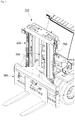
FIG. 1 is a perspective view illustrating a part of a front side of a forklift according to an exemplary embodiment of the present disclosure. -
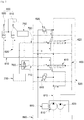
FIG. 2 is a hydraulic circuit diagram for operating a lift cylinder used for the forklift inFIG. 1 . -
FIGS. 3 and4 are hydraulic circuit diagrams illustrating operating states of the lift cylinder which are distinguished from each other. -
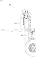
FIGS. 5 and6 are side views of the forklift which illustrate operations of a change-over switch in accordance with raising or lowering of a carriage. -
FIGS. 7 and8 are graphs illustrating operational effects of a comparative example and an experimental example according to the exemplary embodiment of the present disclosure. - Hereinafter, exemplary embodiments of the present disclosure will be described in detail with reference to the accompanying drawings so that those with ordinary skill in the art to which the present disclosure pertains may easily carry out the exemplary embodiments. The present disclosure may be implemented in various different ways, and is not limited to the exemplary embodiments described herein.
- It is noted that the drawings are schematic, and are not illustrated based on actual scales. Relative dimensions and proportions of parts illustrated in the drawings are exaggerated or reduced in size for the purpose of clarity and convenience in the drawings, and any dimension is just illustrative but not restrictive. The same reference numerals designate the same structures, elements or components illustrated in two or more drawings in order to exhibit similar characteristics.
- Exemplary embodiments of the present disclosure illustrate ideal exemplary embodiments of the present disclosure in detail. As a result, various modifications of the drawings are expected. Therefore, the exemplary embodiments are not limited to specific forms in regions illustrated in the drawings, and for example, include modifications of forms by the manufacture thereof.
- Hereinafter, a
forklift 101 according to an exemplary embodiment of the present disclosure will be described with reference toFIGS. 1 to 6 . - As illustrated in
FIG. 1 , theforklift 101 according to the exemplary embodiment of the present disclosure includes amast 200, and acarriage 300 which is raised or lowered along themast 200. - In addition, as illustrated in
FIG. 2 , theforklift 101 according to the exemplary embodiment of the present disclosure includes a firsthydraulic pump 810, a secondhydraulic pump 820, alift cylinder 500, a firsthydraulic line 610, a secondhydraulic line 620, afirst lift spool 410, asecond lift spool 420, afirst pilot line 710, asecond pilot line 720, and an opening/closing valve 760. - In addition, the
forklift 101 according to the exemplary embodiment of the present disclosure may further include a change-over switch 750, anoperating unit 700, afirst relief valve 910, and asecond relief valve 920. - In addition, the
forklift 101 according to the exemplary embodiment of the present disclosure may further include anengine 850 and anoil tank 880. - Each of the first
hydraulic pump 810 and the secondhydraulic pump 820 generates a working fluid. As an example, the firsthydraulic pump 810 and the secondhydraulic pump 820 may be tandem pumps which are installed in series with respect to each other, and the firsthydraulic pump 810 and the secondhydraulic pump 820 are operated by theengine 850 and pump the working fluid stored in theoil tank 880. - In addition, in the exemplary embodiment of the present disclosure, the
engine 850 generates torque by exploding fuel injected by injectors and discontinuously generates torque at a fuel injection interval between the injectors. That is, in the exemplary embodiment of the present disclosure, a sum of torque of theengine 850 for a predetermined period of time means angular momentum of theengine 850. - The
lift cylinder 500 raises or lowers thecarriage 300 by being supplied with the working fluid from the firsthydraulic pump 810 and the secondhydraulic pump 820. - In the exemplary embodiment of the present disclosure, the
lift cylinder 500 may include afirst lift cylinder 510 which is supplied with the working fluid from the firsthydraulic pump 810, and asecond lift cylinder 520 which is supplied with the working fluid from the secondhydraulic pump 820. - The first
hydraulic line 610 delivers the working fluid from the firsthydraulic pump 810 to thefirst lift cylinder 510. Further, the secondhydraulic line 620 delivers the working fluid from the secondhydraulic pump 810 to thesecond lift cylinder 520. - That is, when the working fluid generated by the first
hydraulic pump 810 and the secondhydraulic pump 820 is supplied to thefirst lift cylinder 510 and thesecond lift cylinder 520 through the firsthydraulic line 610 and the secondhydraulic line 620, thecarriage 300 is raised as thefirst lift cylinder 510 and thesecond lift cylinder 520 push thecarriage 300 upward. - The
first lift spool 410 controls the working fluid supplied to thefirst lift cylinder 510 through the firsthydraulic line 610. Further, thesecond lift spool 420 controls the working fluid supplied to thesecond lift cylinder 520 through the secondhydraulic line 620. - In addition, in the exemplary embodiment of the present disclosure, a
main control valve 400 has multiple spools including thefirst lift spool 410 and thesecond lift spool 420. - The
first pilot line 710 transmits a pilot signal for operating thefirst lift spool 410, and thesecond pilot line 720 transmits a pilot signal for operating thesecond lift spool 420. Here, the pilot signal may be transmitted as an electrical signal or a pressure of the working fluid for the pilot signal. - The
operating unit 700 is connected to thefirst pilot line 710 and thesecond pilot line 720 and generates the pilot signal to be transmitted to thefirst lift spool 410 and thesecond lift spool 420. As an example, theoperating unit 700 may include a lift operating lever. - As illustrated in
FIG. 3 , when the pilot signal generated by theoperating unit 700 is transmitted to thefirst lift spool 410 and thesecond lift spool 420 through thefirst pilot line 710 and thesecond pilot line 720, thefirst lift spool 410 and thesecond lift spool 420 perform a change-over operation. That is, as a position of thefirst lift spool 410 and a position of thesecond lift spool 420 are shifted, the working fluid from the firsthydraulic pump 810 and the secondhydraulic pump 820 is supplied to thefirst lift cylinder 510 and thesecond lift cylinder 520 through the firsthydraulic line 610 and the secondhydraulic line 620, respectively. Further, thefirst lift cylinder 510 and thesecond lift cylinder 520 raise thecarriage 300 by using the pressure of the working fluid. - In the exemplary embodiment of the present disclosure, the opening/
closing valve 760 selectively closes any one of thefirst pilot line 710 and thesecond pilot line 720. As an example, inFIGS. 2 to 4 , the opening/closing valve 760 opens or closes thefirst pilot line 710, but the exemplary embodiment of the present disclosure is not limited thereto. That is, the opening/closing valve 760 may open or close thesecond pilot line 720. - In addition, in the exemplary embodiment of the present disclosure, the opening/
closing valve 760 closes any one of thefirst pilot line 710 and thesecond pilot line 720 when thecarriage 300 is raised to a predetermined height or higher, and the opening/closing valve 760 opens both of thefirst pilot line 710 and thesecond pilot line 720 when thecarriage 300 is lowered to a height below a predetermined height. - The change-
over switch 750 is installed at a predetermined height of themast 200 and generates an OFF signal when thecarriage 300 reaches the predetermined height, and the change-over switch 750 generates an ON signal when thecarriage 300 moves below the predetermined height. - The change-
over switch 750 may be configured by various publicly-known methods in the corresponding technical field. As an example, the change-over switch 750 may be a lever switch installed at the predetermined height of themast 200, and the lever switch may be structured to operate as thecarriage 300 is raised. - In addition, the opening/
closing valve 760 may operate based on the signal from the change-over switch 750 to close any one of thefirst pilot line 710 and thesecond pilot line 720 or open both of thefirst pilot line 710 and thesecond pilot line 720. - In addition, in the exemplary embodiment of the present disclosure, the operation of the opening/
closing valve 760 is not necessarily controlled by the change-over switch 750, and the opening/closing valve 760 may be manually manipulated by an operator or may be operated by receiving a signal from other publicly-known sensing means. In this case, the change-over switch 750 may be omitted. - The
first relief valve 910 is installed on the firsthydraulic line 610 and drains the working fluid in the firsthydraulic line 610 when the pressure in the firsthydraulic line 610 becomes a predetermined pressure or higher. - The
second relief valve 920 is installed on the secondhydraulic line 620 and drains the working fluid in the secondhydraulic line 620 when the pressure in the secondhydraulic line 620 becomes a predetermined pressure or higher. - The predetermined pressure may be variously set in consideration of stability of the entire hydraulic system.
- When the
first lift cylinder 510 and thesecond lift cylinder 520 lower thecarriage 300 after raising thecarriage 300 by being supplied with the working fluid, a high pressure is temporarily applied to the firsthydraulic line 610 and the secondhydraulic line 620. In this case, the pressure in the firsthydraulic line 610 and the pressure in the secondhydraulic line 620 are adjusted by thefirst relief valve 910 and thesecond relief valve 920. - However, in a case in which the
carriage 300 is raised to approach the highest position, the pressure of the working fluid in the firsthydraulic line 610 and the secondhydraulic line 620 may be very greatly increased at a point in time at which thecarriage 300 is lowered and the working fluid is released through thefirst relief valve 910 and thesecond relief valve 920, and the increase in pressure of the working fluid has a negative effect on stability of theengine 850. - Specifically, since the increase in pressure of the working fluid means an increase in impulse, the rotational speed of the
engine 850 is decreased due to the increase in impulse, and in some instances, the rotational speed of theengine 850 is decreased to a predetermined level (stall point) or lower, and as a result, the rotational speed cannot be recovered, and a stall may occur. - However, in the exemplary embodiment of the present disclosure, when the
carriage 300 is raised to a predetermined height or higher, the change-over switch 750 operates, and the opening/closing valve 760 closes any one of thefirst pilot line 710 and thesecond pilot line 720, as illustrated inFIG. 4 .FIGS. 5 and6 illustrate a state in which the change-over switch 750 operates as thecarriage 300 is raised. - Therefore, an overall flow rate of the working fluid to be supplied to the
lift cylinder 500 is decreased. This means that a flow rate of the working fluid drained from thelift cylinder 500 is decreased. That is, it is possible to minimize an increase in impulse. Therefore, it is possible to inhibit the rotational speed of theengine 850 from being excessively decreased due to the increase in impulse, and it is possible to prevent a stall of theengine 850. - Meanwhile, in the exemplary embodiment of the present disclosure, the impulse may be further decreased as the predetermined height at which the change-
over switch 750 operates is decreased, and thus it is possible to further ensure stability of theengine 850. However, if the predetermined height is too low, the working fluid is supplied too early to thelift cylinder 500 only by the singlehydraulic pump 820, and as a result, a speed of lifting thecarriage 300 is decreased. Therefore, the predetermined height may be appropriately set in consideration of workability of theforklift 101. - With the above-mentioned configuration, the
forklift 101 according to the exemplary embodiment of the present disclosure may improve stability of theengine 850 by controlling the pressure of the working fluid. - Specifically, the first
hydraulic pump 810 and the secondhydraulic pump 820 actively control a flow rate of the working fluid to be supplied to thelift cylinder 500 to minimize an increase in pressure of the working fluid that occurs when thecarriage 300 is raised or lowered, and as a result, it is possible to prevent an excessive decrease in rotational speed of theengine 850 by decreasing the impulse to be applied to theengine 850. - Hereinafter, an operational effect will be described with reference to
FIGS. 6 and7 in consideration of a comparison between a comparative example and an experimental example according to the exemplary embodiment of the present disclosure. -
FIG. 6 illustrates a change in rotational speed of theengine 850 in the experimental example in which the opening/closing valve 760 closes thefirst pilot line 710 and the firsthydraulic pump 810 cuts off the supply of the working fluid to thelift cylinder 500 when thecarriage 300 is raised to the predetermined height according to the exemplary embodiment of the present disclosure. -
FIG. 7 illustrates a change in rotational speed of theengine 850 in the comparative example in which both of the firsthydraulic pump 810 and the secondhydraulic pump 820 persistently supply the working fluid to the lift cylinder even though thecarriage 300 is raised to the predetermined height or higher. - As illustrated in
FIG. 6 , in the experimental example, it can be seen that when thecarriage 300 is raised to the predetermined height and thus the change-over switch 750 operates (S), the pressure of the working fluid supplied by the firsthydraulic pump 810 is blocked, and the rotational speed of theengine 850 is not decreased even though thecarriage 300 is lowered thereafter. - In contrast, as illustrated in
FIG. 7 , in the comparative example, it can be seen that both of the firsthydraulic pump 810 and the secondhydraulic pump 820 supply the working fluid, and impulse occurs due to an excessive increase in pressure, and as a result, a stall occurs as theengine 850 loses the rotational speed. - While the exemplary embodiments of the present disclosure have been described with reference to the accompanying drawings, those skilled in the art will understand that the present disclosure may be carried out in any other specific form without changing the technical spirit or an essential feature thereof.
- Accordingly, it should be understood that the aforementioned exemplary embodiments are described for illustration in all aspects and are not limited, and the scope of the present disclosure shall be represented by the claims to be described below, and it should be construed that all of the changes or modified forms induced from the meaning and the scope of the claims, and an equivalent concept thereto are included in the scope of the present disclosure.
- The forklift according to the exemplary embodiment of the present disclosure may be used to improve stability of the engine by controlling the pressure of the working fluid.
Claims (6)
- A forklift which comprises a mast and a carriage which is raised or lowered along the mast, the forklift comprising:a first hydraulic pump and a second hydraulic pump each of which generates a working fluid;a lift cylinder which raises or lowers the carriage;a first hydraulic line which supplies the working fluid from the first hydraulic pump to the lift cylinder and a second hydraulic line which supplies the working fluid from the second hydraulic pump to the lift cylinder;a first lift spool which controls the working fluid to be supplied to the lift cylinder through the first hydraulic line and a second lift spool which controls the working fluid to be supplied to the lift cylinder through the second hydraulic line;a first pilot line which transmits a pilot signal for operating the first lift spool and a second pilot line which transmits a pilot signal for operating the second lift spool; andan opening/closing valve which selectively closes any one of the first pilot line and the second pilot line.
- The forklift of claim 1, wherein the opening/closing valve closes any one of the first pilot line and the second pilot line when the carriage is raised to a predetermined height or higher, and the opening/closing valve opens the first pilot line and the second pilot line when the carriage is lowered to a height below the predetermined height.
- The forklift of claim 1, further comprising:a change-over switch which is installed at the predetermined height of the mast, generates an OFF signal when the carriage reaches the predetermined height, and generates an ON signal when the carriage moves below the predetermined height,wherein the opening/closing valve operates based on a signal of the change-over switch.
- The forklift of claim 1, further comprising:an operating unit which includes a lift operating lever,wherein the operating unit generates a pilot signal to be transmitted to the first lift spool and the second lift spool.
- The forklift of claim 1, wherein the lift cylinder includes a first lift cylinder which is connected to the first hydraulic line, and a second lift cylinder which is connected to the second hydraulic line.
- The forklift of claim 1, further comprising:a first relief valve which is installed on the first hydraulic line and drains the working fluid in the first hydraulic line when a pressure in the first hydraulic line becomes a predetermined pressure or higher; anda second relief valve which is installed on the second hydraulic line and drains the working fluid in the second hydraulic line when a pressure in the second hydraulic line becomes a predetermined pressure or higher.
Applications Claiming Priority (2)
| Application Number | Priority Date | Filing Date | Title |
|---|---|---|---|
| KR1020160107916A KR20180022460A (en) | 2016-08-24 | 2016-08-24 | Forklift |
| PCT/KR2017/009253 WO2018038548A1 (en) | 2016-08-24 | 2017-08-24 | Forklift |
Publications (2)
| Publication Number | Publication Date |
|---|---|
| EP3502044A1 true EP3502044A1 (en) | 2019-06-26 |
| EP3502044A4 EP3502044A4 (en) | 2019-08-14 |
Family
ID=61245156
Family Applications (1)
| Application Number | Title | Priority Date | Filing Date |
|---|---|---|---|
| EP17843968.3A Withdrawn EP3502044A4 (en) | 2016-08-24 | 2017-08-24 | FORK LIFT FORK |
Country Status (4)
| Country | Link |
|---|---|
| US (1) | US20190218083A1 (en) |
| EP (1) | EP3502044A4 (en) |
| KR (1) | KR20180022460A (en) |
| WO (1) | WO2018038548A1 (en) |
Family Cites Families (8)
| Publication number | Priority date | Publication date | Assignee | Title |
|---|---|---|---|---|
| JP2002193598A (en) * | 2000-12-28 | 2002-07-10 | Mitsubishi Heavy Ind Ltd | Hydraulic device for controlling forklift and working machine |
| KR100798038B1 (en) * | 2001-09-24 | 2008-01-24 | 두산인프라코어 주식회사 | Mast natural settlement prevention hydraulic system of forklift |
| JP4795682B2 (en) * | 2004-12-27 | 2011-10-19 | Tcm株式会社 | Hydraulic circuit for forklift |
| KR101343831B1 (en) * | 2006-12-27 | 2013-12-20 | 주식회사 두산 | Hydraulic system of forklift truck |
| KR100806923B1 (en) * | 2007-06-28 | 2008-02-22 | 주식회사 파카한일유압 | Solenoid Valve Control Hydraulic Circuit for Safe Operation of Forklift |
| KR101067747B1 (en) * | 2009-07-13 | 2011-09-28 | 주식회사 유압사랑 | Hydraulic Convergence Circuit of Industrial Vehicle |
| KR20110127343A (en) * | 2010-05-19 | 2011-11-25 | 두산산업차량 주식회사 | Ascent rate control device of heavy machinery |
| KR101688233B1 (en) * | 2010-12-01 | 2016-12-20 | 주식회사 두산 | Anti-engine stall system for a heavy equipment |
-
2016
- 2016-08-24 KR KR1020160107916A patent/KR20180022460A/en not_active Ceased
-
2017
- 2017-08-24 EP EP17843968.3A patent/EP3502044A4/en not_active Withdrawn
- 2017-08-24 US US16/327,470 patent/US20190218083A1/en not_active Abandoned
- 2017-08-24 WO PCT/KR2017/009253 patent/WO2018038548A1/en not_active Ceased
Also Published As
| Publication number | Publication date |
|---|---|
| KR20180022460A (en) | 2018-03-06 |
| US20190218083A1 (en) | 2019-07-18 |
| EP3502044A4 (en) | 2019-08-14 |
| WO2018038548A1 (en) | 2018-03-01 |
Similar Documents
| Publication | Publication Date | Title |
|---|---|---|
| US10392781B2 (en) | Wheel loader | |
| US10408238B2 (en) | Control strategy for hydraulic actuator with a pair of independent metering valves | |
| JP5192601B1 (en) | Work vehicle and control method of work vehicle | |
| JP5228132B1 (en) | Wheel loader | |
| US8666610B2 (en) | Work vehicle and method for controlling work vehicle | |
| EP2667060B1 (en) | Wheel loader and method for controlling wheel loader | |
| US20140283508A1 (en) | Drive system for hydraulic closed circuit | |
| US11035462B2 (en) | Work vehicle and control method for work vehicle | |
| US8532886B1 (en) | Work vehicle and control method for work vehicle | |
| KR20130124163A (en) | Swirl flow control system for construction equipment and method of controlling the same | |
| GB2448652A (en) | Hydraulic traveling vehicle and method of controlling hydraulic traveling vehicle | |
| CN104884819A (en) | Fail operational modes for an electro-hydraulic system | |
| JPWO2015178316A1 (en) | Excavator and control method thereof | |
| EP2980390B1 (en) | Engine speed controller of work machine | |
| US20160297657A1 (en) | Forklift | |
| US20190218083A1 (en) | Forklift | |
| US11891780B2 (en) | Working machine | |
| US20200355280A1 (en) | Control valve | |
| US20190003494A1 (en) | Hydraulic driving device for cargo handling vehicle | |
| US10533304B2 (en) | System and methods for controlled lowering and lifting of a load | |
| JP6619939B2 (en) | Hydraulic drive system | |
| JP2016000647A (en) | Hydraulic drive device for cargo vehicle | |
| JP6488990B2 (en) | Hydraulic drive device for cargo handling vehicle | |
| EP3078573A1 (en) | Forklift | |
| JP2018012576A (en) | Industrial vehicle |
Legal Events
| Date | Code | Title | Description |
|---|---|---|---|
| STAA | Information on the status of an ep patent application or granted ep patent |
Free format text: STATUS: THE INTERNATIONAL PUBLICATION HAS BEEN MADE |
|
| PUAI | Public reference made under article 153(3) epc to a published international application that has entered the european phase |
Free format text: ORIGINAL CODE: 0009012 |
|
| STAA | Information on the status of an ep patent application or granted ep patent |
Free format text: STATUS: REQUEST FOR EXAMINATION WAS MADE |
|
| 17P | Request for examination filed |
Effective date: 20190320 |
|
| AK | Designated contracting states |
Kind code of ref document: A1 Designated state(s): AL AT BE BG CH CY CZ DE DK EE ES FI FR GB GR HR HU IE IS IT LI LT LU LV MC MK MT NL NO PL PT RO RS SE SI SK SM TR |
|
| AX | Request for extension of the european patent |
Extension state: BA ME |
|
| A4 | Supplementary search report drawn up and despatched |
Effective date: 20190716 |
|
| RIC1 | Information provided on ipc code assigned before grant |
Ipc: F02D 29/04 20060101ALI20190710BHEP Ipc: F15B 11/16 20060101ALI20190710BHEP Ipc: B66F 9/22 20060101AFI20190710BHEP Ipc: B66F 9/075 20060101ALI20190710BHEP Ipc: B66F 17/00 20060101ALI20190710BHEP |
|
| DAV | Request for validation of the european patent (deleted) | ||
| DAX | Request for extension of the european patent (deleted) | ||
| STAA | Information on the status of an ep patent application or granted ep patent |
Free format text: STATUS: THE APPLICATION HAS BEEN WITHDRAWN |
|
| 18W | Application withdrawn |
Effective date: 20200130 |