EP3501775A1 - Method of separating materials from an object - Google Patents
Method of separating materials from an object Download PDFInfo
- Publication number
- EP3501775A1 EP3501775A1 EP17306923.8A EP17306923A EP3501775A1 EP 3501775 A1 EP3501775 A1 EP 3501775A1 EP 17306923 A EP17306923 A EP 17306923A EP 3501775 A1 EP3501775 A1 EP 3501775A1
- Authority
- EP
- European Patent Office
- Prior art keywords
- particles
- density
- iii
- solution
- acidic
- Prior art date
- Legal status (The legal status is an assumption and is not a legal conclusion. Google has not performed a legal analysis and makes no representation as to the accuracy of the status listed.)
- Withdrawn
Links
Classifications
-
- C—CHEMISTRY; METALLURGY
- C08—ORGANIC MACROMOLECULAR COMPOUNDS; THEIR PREPARATION OR CHEMICAL WORKING-UP; COMPOSITIONS BASED THEREON
- C08J—WORKING-UP; GENERAL PROCESSES OF COMPOUNDING; AFTER-TREATMENT NOT COVERED BY SUBCLASSES C08B, C08C, C08F, C08G or C08H
- C08J11/00—Recovery or working-up of waste materials
- C08J11/04—Recovery or working-up of waste materials of polymers
- C08J11/10—Recovery or working-up of waste materials of polymers by chemically breaking down the molecular chains of polymers or breaking of crosslinks, e.g. devulcanisation
- C08J11/16—Recovery or working-up of waste materials of polymers by chemically breaking down the molecular chains of polymers or breaking of crosslinks, e.g. devulcanisation by treatment with inorganic material
-
- B—PERFORMING OPERATIONS; TRANSPORTING
- B29—WORKING OF PLASTICS; WORKING OF SUBSTANCES IN A PLASTIC STATE IN GENERAL
- B29B—PREPARATION OR PRETREATMENT OF THE MATERIAL TO BE SHAPED; MAKING GRANULES OR PREFORMS; RECOVERY OF PLASTICS OR OTHER CONSTITUENTS OF WASTE MATERIAL CONTAINING PLASTICS
- B29B17/00—Recovery of plastics or other constituents of waste material containing plastics
- B29B17/02—Separating plastics from other materials
-
- B—PERFORMING OPERATIONS; TRANSPORTING
- B29—WORKING OF PLASTICS; WORKING OF SUBSTANCES IN A PLASTIC STATE IN GENERAL
- B29B—PREPARATION OR PRETREATMENT OF THE MATERIAL TO BE SHAPED; MAKING GRANULES OR PREFORMS; RECOVERY OF PLASTICS OR OTHER CONSTITUENTS OF WASTE MATERIAL CONTAINING PLASTICS
- B29B17/00—Recovery of plastics or other constituents of waste material containing plastics
- B29B17/04—Disintegrating plastics, e.g. by milling
- B29B17/0404—Disintegrating plastics, e.g. by milling to powder
-
- C—CHEMISTRY; METALLURGY
- C08—ORGANIC MACROMOLECULAR COMPOUNDS; THEIR PREPARATION OR CHEMICAL WORKING-UP; COMPOSITIONS BASED THEREON
- C08J—WORKING-UP; GENERAL PROCESSES OF COMPOUNDING; AFTER-TREATMENT NOT COVERED BY SUBCLASSES C08B, C08C, C08F, C08G or C08H
- C08J11/00—Recovery or working-up of waste materials
- C08J11/04—Recovery or working-up of waste materials of polymers
-
- B—PERFORMING OPERATIONS; TRANSPORTING
- B29—WORKING OF PLASTICS; WORKING OF SUBSTANCES IN A PLASTIC STATE IN GENERAL
- B29B—PREPARATION OR PRETREATMENT OF THE MATERIAL TO BE SHAPED; MAKING GRANULES OR PREFORMS; RECOVERY OF PLASTICS OR OTHER CONSTITUENTS OF WASTE MATERIAL CONTAINING PLASTICS
- B29B17/00—Recovery of plastics or other constituents of waste material containing plastics
- B29B17/02—Separating plastics from other materials
- B29B2017/0203—Separating plastics from plastics
-
- B—PERFORMING OPERATIONS; TRANSPORTING
- B29—WORKING OF PLASTICS; WORKING OF SUBSTANCES IN A PLASTIC STATE IN GENERAL
- B29B—PREPARATION OR PRETREATMENT OF THE MATERIAL TO BE SHAPED; MAKING GRANULES OR PREFORMS; RECOVERY OF PLASTICS OR OTHER CONSTITUENTS OF WASTE MATERIAL CONTAINING PLASTICS
- B29B17/00—Recovery of plastics or other constituents of waste material containing plastics
- B29B17/02—Separating plastics from other materials
- B29B2017/0213—Specific separating techniques
- B29B2017/0217—Mechanical separating techniques; devices therefor
- B29B2017/0231—Centrifugating, cyclones
-
- B—PERFORMING OPERATIONS; TRANSPORTING
- B29—WORKING OF PLASTICS; WORKING OF SUBSTANCES IN A PLASTIC STATE IN GENERAL
- B29B—PREPARATION OR PRETREATMENT OF THE MATERIAL TO BE SHAPED; MAKING GRANULES OR PREFORMS; RECOVERY OF PLASTICS OR OTHER CONSTITUENTS OF WASTE MATERIAL CONTAINING PLASTICS
- B29B17/00—Recovery of plastics or other constituents of waste material containing plastics
- B29B17/02—Separating plastics from other materials
- B29B2017/0213—Specific separating techniques
- B29B2017/0217—Mechanical separating techniques; devices therefor
- B29B2017/0237—Mechanical separating techniques; devices therefor using density difference
- B29B2017/0244—Mechanical separating techniques; devices therefor using density difference in liquids
-
- B—PERFORMING OPERATIONS; TRANSPORTING
- B29—WORKING OF PLASTICS; WORKING OF SUBSTANCES IN A PLASTIC STATE IN GENERAL
- B29B—PREPARATION OR PRETREATMENT OF THE MATERIAL TO BE SHAPED; MAKING GRANULES OR PREFORMS; RECOVERY OF PLASTICS OR OTHER CONSTITUENTS OF WASTE MATERIAL CONTAINING PLASTICS
- B29B17/00—Recovery of plastics or other constituents of waste material containing plastics
- B29B17/02—Separating plastics from other materials
- B29B2017/0213—Specific separating techniques
- B29B2017/0293—Dissolving the materials in gases or liquids
- B29B2017/0296—Dissolving the materials in aqueous alkaline solutions, e.g. NaOH or KOH
-
- B—PERFORMING OPERATIONS; TRANSPORTING
- B29—WORKING OF PLASTICS; WORKING OF SUBSTANCES IN A PLASTIC STATE IN GENERAL
- B29B—PREPARATION OR PRETREATMENT OF THE MATERIAL TO BE SHAPED; MAKING GRANULES OR PREFORMS; RECOVERY OF PLASTICS OR OTHER CONSTITUENTS OF WASTE MATERIAL CONTAINING PLASTICS
- B29B17/00—Recovery of plastics or other constituents of waste material containing plastics
- B29B17/04—Disintegrating plastics, e.g. by milling
- B29B2017/0424—Specific disintegrating techniques; devices therefor
- B29B2017/044—Knives
-
- B—PERFORMING OPERATIONS; TRANSPORTING
- B29—WORKING OF PLASTICS; WORKING OF SUBSTANCES IN A PLASTIC STATE IN GENERAL
- B29B—PREPARATION OR PRETREATMENT OF THE MATERIAL TO BE SHAPED; MAKING GRANULES OR PREFORMS; RECOVERY OF PLASTICS OR OTHER CONSTITUENTS OF WASTE MATERIAL CONTAINING PLASTICS
- B29B17/00—Recovery of plastics or other constituents of waste material containing plastics
- B29B17/04—Disintegrating plastics, e.g. by milling
- B29B2017/0424—Specific disintegrating techniques; devices therefor
- B29B2017/0468—Crushing, i.e. disintegrating into small particles
-
- B—PERFORMING OPERATIONS; TRANSPORTING
- B29—WORKING OF PLASTICS; WORKING OF SUBSTANCES IN A PLASTIC STATE IN GENERAL
- B29K—INDEXING SCHEME ASSOCIATED WITH SUBCLASSES B29B, B29C OR B29D, RELATING TO MOULDING MATERIALS OR TO MATERIALS FOR MOULDS, REINFORCEMENTS, FILLERS OR PREFORMED PARTS, e.g. INSERTS
- B29K2021/00—Use of unspecified rubbers as moulding material
-
- B—PERFORMING OPERATIONS; TRANSPORTING
- B29—WORKING OF PLASTICS; WORKING OF SUBSTANCES IN A PLASTIC STATE IN GENERAL
- B29K—INDEXING SCHEME ASSOCIATED WITH SUBCLASSES B29B, B29C OR B29D, RELATING TO MOULDING MATERIALS OR TO MATERIALS FOR MOULDS, REINFORCEMENTS, FILLERS OR PREFORMED PARTS, e.g. INSERTS
- B29K2027/00—Use of polyvinylhalogenides or derivatives thereof as moulding material
- B29K2027/06—PVC, i.e. polyvinylchloride
-
- B—PERFORMING OPERATIONS; TRANSPORTING
- B29—WORKING OF PLASTICS; WORKING OF SUBSTANCES IN A PLASTIC STATE IN GENERAL
- B29K—INDEXING SCHEME ASSOCIATED WITH SUBCLASSES B29B, B29C OR B29D, RELATING TO MOULDING MATERIALS OR TO MATERIALS FOR MOULDS, REINFORCEMENTS, FILLERS OR PREFORMED PARTS, e.g. INSERTS
- B29K2027/00—Use of polyvinylhalogenides or derivatives thereof as moulding material
- B29K2027/12—Use of polyvinylhalogenides or derivatives thereof as moulding material containing fluorine
-
- B—PERFORMING OPERATIONS; TRANSPORTING
- B29—WORKING OF PLASTICS; WORKING OF SUBSTANCES IN A PLASTIC STATE IN GENERAL
- B29K—INDEXING SCHEME ASSOCIATED WITH SUBCLASSES B29B, B29C OR B29D, RELATING TO MOULDING MATERIALS OR TO MATERIALS FOR MOULDS, REINFORCEMENTS, FILLERS OR PREFORMED PARTS, e.g. INSERTS
- B29K2075/00—Use of PU, i.e. polyureas or polyurethanes or derivatives thereof, as moulding material
-
- B—PERFORMING OPERATIONS; TRANSPORTING
- B29—WORKING OF PLASTICS; WORKING OF SUBSTANCES IN A PLASTIC STATE IN GENERAL
- B29K—INDEXING SCHEME ASSOCIATED WITH SUBCLASSES B29B, B29C OR B29D, RELATING TO MOULDING MATERIALS OR TO MATERIALS FOR MOULDS, REINFORCEMENTS, FILLERS OR PREFORMED PARTS, e.g. INSERTS
- B29K2083/00—Use of polymers having silicon, with or without sulfur, nitrogen, oxygen, or carbon only, in the main chain, as moulding material
-
- B—PERFORMING OPERATIONS; TRANSPORTING
- B29—WORKING OF PLASTICS; WORKING OF SUBSTANCES IN A PLASTIC STATE IN GENERAL
- B29K—INDEXING SCHEME ASSOCIATED WITH SUBCLASSES B29B, B29C OR B29D, RELATING TO MOULDING MATERIALS OR TO MATERIALS FOR MOULDS, REINFORCEMENTS, FILLERS OR PREFORMED PARTS, e.g. INSERTS
- B29K2677/00—Use of PA, i.e. polyamides, e.g. polyesteramides or derivatives thereof, for preformed parts, e.g. for inserts
-
- B—PERFORMING OPERATIONS; TRANSPORTING
- B29—WORKING OF PLASTICS; WORKING OF SUBSTANCES IN A PLASTIC STATE IN GENERAL
- B29K—INDEXING SCHEME ASSOCIATED WITH SUBCLASSES B29B, B29C OR B29D, RELATING TO MOULDING MATERIALS OR TO MATERIALS FOR MOULDS, REINFORCEMENTS, FILLERS OR PREFORMED PARTS, e.g. INSERTS
- B29K2683/00—Use of polymers having silicon, with or without sulfur, nitrogen, oxygen or carbon only, in the main chain, for preformed parts, e.g. for inserts
-
- B—PERFORMING OPERATIONS; TRANSPORTING
- B29—WORKING OF PLASTICS; WORKING OF SUBSTANCES IN A PLASTIC STATE IN GENERAL
- B29L—INDEXING SCHEME ASSOCIATED WITH SUBCLASS B29C, RELATING TO PARTICULAR ARTICLES
- B29L2022/00—Hollow articles
- B29L2022/02—Inflatable articles
- B29L2022/027—Air bags
-
- C—CHEMISTRY; METALLURGY
- C08—ORGANIC MACROMOLECULAR COMPOUNDS; THEIR PREPARATION OR CHEMICAL WORKING-UP; COMPOSITIONS BASED THEREON
- C08J—WORKING-UP; GENERAL PROCESSES OF COMPOUNDING; AFTER-TREATMENT NOT COVERED BY SUBCLASSES C08B, C08C, C08F, C08G or C08H
- C08J2377/00—Characterised by the use of polyamides obtained by reactions forming a carboxylic amide link in the main chain; Derivatives of such polymers
- C08J2377/02—Polyamides derived from omega-amino carboxylic acids or from lactams thereof
-
- C—CHEMISTRY; METALLURGY
- C08—ORGANIC MACROMOLECULAR COMPOUNDS; THEIR PREPARATION OR CHEMICAL WORKING-UP; COMPOSITIONS BASED THEREON
- C08J—WORKING-UP; GENERAL PROCESSES OF COMPOUNDING; AFTER-TREATMENT NOT COVERED BY SUBCLASSES C08B, C08C, C08F, C08G or C08H
- C08J2377/00—Characterised by the use of polyamides obtained by reactions forming a carboxylic amide link in the main chain; Derivatives of such polymers
- C08J2377/06—Polyamides derived from polyamines and polycarboxylic acids
-
- C—CHEMISTRY; METALLURGY
- C08—ORGANIC MACROMOLECULAR COMPOUNDS; THEIR PREPARATION OR CHEMICAL WORKING-UP; COMPOSITIONS BASED THEREON
- C08J—WORKING-UP; GENERAL PROCESSES OF COMPOUNDING; AFTER-TREATMENT NOT COVERED BY SUBCLASSES C08B, C08C, C08F, C08G or C08H
- C08J2483/00—Characterised by the use of macromolecular compounds obtained by reactions forming in the main chain of the macromolecule a linkage containing silicon with or without sulfur, nitrogen, oxygen, or carbon only; Derivatives of such polymers
- C08J2483/04—Polysiloxanes
-
- Y—GENERAL TAGGING OF NEW TECHNOLOGICAL DEVELOPMENTS; GENERAL TAGGING OF CROSS-SECTIONAL TECHNOLOGIES SPANNING OVER SEVERAL SECTIONS OF THE IPC; TECHNICAL SUBJECTS COVERED BY FORMER USPC CROSS-REFERENCE ART COLLECTIONS [XRACs] AND DIGESTS
- Y02—TECHNOLOGIES OR APPLICATIONS FOR MITIGATION OR ADAPTATION AGAINST CLIMATE CHANGE
- Y02P—CLIMATE CHANGE MITIGATION TECHNOLOGIES IN THE PRODUCTION OR PROCESSING OF GOODS
- Y02P20/00—Technologies relating to chemical industry
- Y02P20/141—Feedstock
- Y02P20/143—Feedstock the feedstock being recycled material, e.g. plastics
-
- Y—GENERAL TAGGING OF NEW TECHNOLOGICAL DEVELOPMENTS; GENERAL TAGGING OF CROSS-SECTIONAL TECHNOLOGIES SPANNING OVER SEVERAL SECTIONS OF THE IPC; TECHNICAL SUBJECTS COVERED BY FORMER USPC CROSS-REFERENCE ART COLLECTIONS [XRACs] AND DIGESTS
- Y02—TECHNOLOGIES OR APPLICATIONS FOR MITIGATION OR ADAPTATION AGAINST CLIMATE CHANGE
- Y02W—CLIMATE CHANGE MITIGATION TECHNOLOGIES RELATED TO WASTEWATER TREATMENT OR WASTE MANAGEMENT
- Y02W30/00—Technologies for solid waste management
- Y02W30/50—Reuse, recycling or recovery technologies
- Y02W30/52—Mechanical processing of waste for the recovery of materials, e.g. crushing, shredding, separation or disassembly
-
- Y—GENERAL TAGGING OF NEW TECHNOLOGICAL DEVELOPMENTS; GENERAL TAGGING OF CROSS-SECTIONAL TECHNOLOGIES SPANNING OVER SEVERAL SECTIONS OF THE IPC; TECHNICAL SUBJECTS COVERED BY FORMER USPC CROSS-REFERENCE ART COLLECTIONS [XRACs] AND DIGESTS
- Y02—TECHNOLOGIES OR APPLICATIONS FOR MITIGATION OR ADAPTATION AGAINST CLIMATE CHANGE
- Y02W—CLIMATE CHANGE MITIGATION TECHNOLOGIES RELATED TO WASTEWATER TREATMENT OR WASTE MANAGEMENT
- Y02W30/00—Technologies for solid waste management
- Y02W30/50—Reuse, recycling or recovery technologies
- Y02W30/62—Plastics recycling; Rubber recycling
Definitions
- thermoplastic fibers for specific applications, such as flame retardancy, mechanical strength, electrical and/or thermal conductivity, or the protection of personnel. They are typically surface-treated with a coating, for example applied by coating.
- coated technical textiles include airbags, which are inflatable protective bags used for the protection of the occupants of a vehicle.
- Such articles generally comprise a bag based on polyamide or on polyester, generally in the form of woven fabrics of fibers, or several layers, and a silicone coating on one of the faces.
- Airbags are widely manufactured by deposition of a silicone composition which can crosslink to form a thin layer of silicone elastomer.
- thermoplastic fibers due to the incompatibility of the thermoplastic fibers and the polymers used for the coating, such as silicone. This is because it is very difficult to mechanically dissociate the two materials. Their direct reuse without pretreatment results in a poor performance due to the presence of coating, which also adversely affects the surface appearance of the molded parts and often results in severe fouling of the molds during the injection.
- US 2014/0042252 A1 provides a process for treating technical textiles comprising thermoplastic fibers in the coating material, using the principle of centrifugal decanting to separate the fiber residues and the coating material. Further disclosed in US 2014/0042252 A1 is a process for the manufacture of a thermoplastic composition, in particular for molding, obtained by use of the fiber residues as obtained and optionally of reinforcing fillers. The present invention aims at providing an improved process for recycling technical objects comprising at least two different materials.
- the present invention therefore relates to the subject matter defined in the following items 1 to 28.
- the present invention relates to a process for treating an object comprising at least two different materials which are bound to each other.
- the density of the first material is different from the density of the second material.
- the density of the first material (pA) and the density of the second material (pB) are such that they fulfil the following relationship: 2 ⁇ ⁇ A ⁇ ⁇ B ⁇ A + ⁇ B > 0.03 , wherein pA is the density of the first material (A), and pB is the density of the second material (B).
- the density of the first material and the density of the second material are such that they fulfil the following relationship: 2 ⁇ ⁇ A ⁇ ⁇ B ⁇ A + ⁇ B > 0.04.
- the technical object typically comprises two different materials.
- the technical object to be treated in accordance with the present invention comprises at least three or at least four different materials.
- the technical object to be treated substantially consists of two different materials.
- the object to be treated substantially consists of three different materials or of four different materials.
- the technical objects may be fibers, woven or nonwoven fabrics, extruded or blow-molded articles such as films, sheets and multilayer objects.
- the first material of the technical object to be treated is a thermoplastic polymer, more preferably, it is a polyamide such as PA66.
- the second material can be composed of a single polymer or of a mixture of polymers, and it can be thermoplastic or thermosetting.
- the first material is preferably mixed with a surface coated or intermingled or co-mingled or interwoven or laminated or coextruded second material.
- the second material is preferably selected from silicones, polyurethanes, fluorinated polymers, rubbers and the like. More preferably, the second material is a silicone, a polyurethane coating, a polyurethane fiber or a fluorinated polymer.
- Typical textile objects to be treated in accordance with this invention are polyamide/silicone airbags, elasticized polyamide/polyurethane textiles, polyamide or polyester/PTFE textile tissues, polyamide cord fibers / rubber compounds from tires etc.
- the first material is a polyamide
- the second material is a silicone.
- the first material is a polyamide
- the second material is a polyurethane.
- the first material is a polyamide
- the second material is polytetrafluoroethylene (PTFE).
- PTFE polytetrafluoroethylene
- the first material is a polyester, and the second material is PTFE.
- the first material is a polyamide cord fiber, and the second material is a rubber.
- Typical extruded or blow-molded multilayer parts are multilayer films for packaging, multilayer pipes and cables, bottles and reservoirs.
- the technical objects can be provided from industrial waste during fabrication of parts such as airbags, elasticized fibers, tissues, clothes, films or end-of-life waste, such as "post-consumer" waste.
- An example can be the airbag fabric (i.e. polyamide fabric coated with silicone) that generates bi-component textile waste during both an airbag fabrication and after the end of life of a vehicle, by recovery of airbags from the vehicles.
- the process of the present invention comprises physically treating the object to obtain micronized particles.
- This step of physical treatment is typically a conversion of a technical object into small pieces. It may include cutting the objects into smaller pieces, e.g. by blade-cutting (e.g. by guillotine-type and/or by rotative blades) followed by disaggregation and pulverization by a micronization process such as mechanical scratching and/or fiber shredding, for example with a rotor/stator plus grid micronizer or a rotor/stator air classifier micronizer, or a cryogenic impact mill, or any other equipment available in the state of the art.
- micronized refers to particles having a main dimension of less than 10 mm. The shape or aspect ratio of the micronized particles is not limited.
- the micronized particles obtained by the physical treatment typically have a main dimension between 15 ⁇ m and 5 mm, preferably from 0.1 mm to 2 mm.
- the term "main dimension" as used herein, is synonymous to the median diameter (d50 value).
- the particle size distribution of the objects can be obtained by laser diffraction measurement, in particular on a particle sizer from Malvern, for example by using the wet route module. All the particles are compared to spheres, without taking into account their aspect ratio in this calculation.
- the d50 mesh is the dimension such that 50% of the particles are smaller than this dimension and 50% of the particles are larger than this dimension.
- the laser diffraction particle size analysis can be carried out according to the instructions of the standard AFNOR ISO 13320-1.
- the particle size distribution can be measured according to the following protocol: A Malvern Master Sizer 2000 light diffraction particle sizer equipped with the hydro S module is used, after suspending the sample in ethanol.
- the measurement conditions are as follows: Stirring in the cell of the particle sizer: 1,400 rev/min; optical model: Fraunhofer; measurement range: from 100 nm to 3,000 ⁇ m.
- the population of particles obtained in step (i) typically comprises at least three kinds of particles:
- the method further comprises, as the next step, suspending the micronized particles in an acidic solution or in an alkaline solution, depending on the nature of materials, to at least partially separate the first material from the second material.
- the acidic or alkaline solution typically is an aqueous solution comprising water and an acid or a base. If the aqueous solution is an acidic solution, the pH of the aqueous solution is preferably less than 3, more preferably less than 2, or even less than 1.5 or less than 1. If the aqueous solution is an alkaline solution, the pH of the alkaline solution is preferably at least 10, more preferably at least 11, more preferably at least 12, most preferably at least 13.
- Preferred acids to be used for preparing the acidic solution are hydrochloric acid or sulfuric acid.
- Preferred compounds for adjusting an alkaline pH in the alkaline solution are sodium hydroxide or potassium hydroxide.
- the acidic or alkaline solution may comprise further compounds such as salts, e.g. sodium chloride.
- the suspended particles are incubated or kept in the acidic or alkaline solution for a sufficient period of time to achieve at least a partial separation of the first material from the second material.
- the incubation time is at least 10 minutes.
- the incubation time is at least 30 minutes, or at least 1 hour , or at least 3 hours, or at least 5 hours, or at least 6 hours.
- Typical incubation periods are in the range from 10 minutes to 12 hours, or 1 hour to 10 hours, or 2 hours to 8 hours, or 3 hours to 6 hours.
- the temperature of the aqueous solution and/or of the suspension is preferably in the range from 15°C to 95°C, preferably from 30°C to 70°C.
- step (ii) can be carried out batch-wise or continuously, e.g. by slurry treatment or solid/liquid contact, by continuous stirred tank reactor, by reactor in cascade, or by tubular reactors.
- the residual liquid is removed from the suspension and the solids are preferably recovered from the suspension.
- the recovered solids typically have a water content of less than 30%, preferably less than 25%, more preferably less than 20%, most preferably less than 15%.
- the residual alkaline or acid solution can be reclycled in the system after pH adjustment.
- the recovered solids are then suspended in a liquid, preferably in an aqueous solution, having a density which is between the densities of the first material and the second material.
- a liquid preferably in an aqueous solution
- This liquid is referred also as “liquid C” or “solution C” hereinafter. Accordingly, the density of the liquid C and the densities of the first material (A) and of the second material (B) follow the following relationship: ⁇ C ⁇ ⁇ A ; ⁇ B
- the density of the solution at the process temperature have to be in the following range: if ⁇ A > ⁇ B : ⁇ A + ⁇ B / 2 ⁇ ⁇ C ⁇ ⁇ A if ⁇ A > ⁇ B : ⁇ A + ⁇ B / 2 ⁇ ⁇ C ⁇ ⁇ A
- the density of the solution the process temperature has to be in the following range. if ⁇ A > ⁇ B : ⁇ A ⁇ 0 , 98 ⁇ ⁇ C ⁇ ⁇ A if ⁇ A > ⁇ B : ⁇ A ⁇ 1 , 02 > ⁇ C > ⁇ A
- the liquid C typically has a density in the range from 1 and 1.5, in particular between 1.03 and 1.5, for example between 1 and 1.12, and more particularly between 1.05 and 1.12 g/cm 3 .
- liquid C does not comprise an alcohol; In a specific embodiment liquid C does not comprise a solvent other than water.
- the process temperature at this step is in the range from 15°C to 95°C, preferably from 30°C to 70°C.
- the liquid C can be composed of water and dissolved salt.
- This salt can be added to water or can be directly generated in C to form that neutralization of the chemical agent from the previous step by adjusting the pH of the liquid C to a pH in the range between 5 and 10, in order to avoid acid hydrolysis of the materials, e.g. of the polyamide.
- the pH can be measured from a sample of the liquid C or can be directly measured on the slurry in the presence of first and second material (e.g. fiber A and particle B), in a continuous way.
- liquid density of liquid C is measured at the usage temperature according to any methodology known in the art, e.g. with a densimeter or a continuous Coriolis flow meter. If necessary, an adjustment can be done by addition of salt or acid and base couple.
- a typical salt concentration is from 5 to 30%, preferably from 8 to 20%.
- a slurry made of fibers A and particles B dispersed in solution C is obtained and hence A and B can be separated by density gradient.
- the separation by the centrifugal force of the particles essentially consisting of the first material, on the one hand, and of the particles essentially consisting of the second material, on the other hand, can be carried out in various ways by the centrifugal force.
- a technique of centrifugal decanting or centrifuging based on the centrifugal force created by rotating the suspension in particular at high speed, in a rotating machine, such as a centrifuge, a bowl centrifuge, a bowl screw centrifuge or a plate separator.
- HACDs horizontal-axis centrifugal decanters
- the suspension enters a cylindroconical bowl in which a screw conveyor is positioned.
- the liquid forms a liquid ring in the bowl, whereas the solids, by the centrifugal effect, are flattened against the surface of the bowl.
- the centrate is then discharged by overflowing at the level of the cylindrical part of the machine, whereas the solids deposited on the bowl are conveyed by the screw in the direction of the cylindrical part of the machine, where they are discharged.
- centrifugal decanter such as mentioned in the application WO9740941 . Mention may also be made of the centrifuges from Flottweg, such as the Tricanter®, the Sedicanter® and the Sorticanter®.
- the suspension to be separated is then introduced into the decanter by an axial feed pipe.
- the product is gradually accelerated in the dispensing chamber before being introduced into the bowl by appropriate orifices.
- the bowl of cylindroconical shape, rotates at an optimized speed.
- the suspension rotates with the bowl at the operating speed and forms a concentric layer on the internal wall of the bowl.
- the solid particles present in the suspension are flattened against the wall of the bowl under the effect of the centrifugal field.
- the diameter, the length of the cylindrical section and the angle of the cone are defined according to the specific requirements of the application.
- the conveying screw rotates at a different speed from that of the bowl, which allows it to convey the solid particles which have decanted toward the conical end of the bowl.
- the differential speed determines the retention time of the solid particles in the bowl and consequently the dryness of the solids extracted. It can be adjusted while running, for the purpose of optimizing the separation.
- the screw pitch and the number of threads form part of the main design variables.
- the separated solids are discharged at the conical end of the bowl into the sediment collector and then fall by gravity into the discharge hopper.
- the separated first material and/or the separated second material may be washed, dried, and shaped in to granules or sinterized particles. Drying may be necessary to remove or reduce the content of water or other liquid of the recovered particles.
- the drying techniques can be mechanical or thermal. Preference is given in particular to evaporation by hot air.
- the heat can be transferred by convection, infrared radiation, conduction, microwaves or high frequency.
- the salt solution can be recycled after separation from the solid.
- Airbags based on polyamide 66 coated on face with crosslinked silicone were used in this example.
- the content of silicone was 10% by weight.
- the airbags were industrial waste.
- the air-bags were cut up, ground and micronized:
- the residual product was composed of
- the size of these particles was measured by optical microscopy and by laser diffraction measurement.
- the particles exhibited a median diameter D50 from 108 to 141 ⁇ m.
- the fibers, particles, agglomerate were suspended in a liquid having a density of 1.100, comprising sodium hydroxide and exhibiting a pH of 14.
- the fibers and silicone particles were separated from sodium hydroxide solution by a pusher centrifuge (Solid/Liquid separator).
- the separation phase there was no additional treatment in this phase.
- the comparative example corresponds to the disclosure in the experimental part of US 2014/0042252 A1 .
- the suspensions were then fed to a Solid / Solid / Liquid separator, used for the separation of the polyamide particles and the coating particles, by difference of density, with the following parameters:
Landscapes
- Engineering & Computer Science (AREA)
- Chemical & Material Sciences (AREA)
- Environmental & Geological Engineering (AREA)
- Mechanical Engineering (AREA)
- Life Sciences & Earth Sciences (AREA)
- Health & Medical Sciences (AREA)
- Sustainable Development (AREA)
- Chemical Kinetics & Catalysis (AREA)
- Medicinal Chemistry (AREA)
- Polymers & Plastics (AREA)
- Organic Chemistry (AREA)
- Separation, Recovery Or Treatment Of Waste Materials Containing Plastics (AREA)
- Separation Of Solids By Using Liquids Or Pneumatic Power (AREA)
Abstract
The present invention relates to a process for treating an object comprising a first material and a second material bound to the first material by centrifugal force.
Description
- Many technical products are composite objects and comprise two or more different materials. For example, technical textiles are often knitted, woven or nonwoven and composed of thermoplastic fibers for specific applications, such as flame retardancy, mechanical strength, electrical and/or thermal conductivity, or the protection of personnel. They are typically surface-treated with a coating, for example applied by coating.
- Examples of coated technical textiles include airbags, which are inflatable protective bags used for the protection of the occupants of a vehicle. Such articles generally comprise a bag based on polyamide or on polyester, generally in the form of woven fabrics of fibers, or several layers, and a silicone coating on one of the faces. Airbags are widely manufactured by deposition of a silicone composition which can crosslink to form a thin layer of silicone elastomer.
- A problem is the recycling of these technical objects, such as coated airbags, due to the incompatibility of the thermoplastic fibers and the polymers used for the coating, such as silicone. This is because it is very difficult to mechanically dissociate the two materials. Their direct reuse without pretreatment results in a poor performance due to the presence of coating, which also adversely affects the surface appearance of the molded parts and often results in severe fouling of the molds during the injection.
-
US 2014/0042252 A1 provides a process for treating technical textiles comprising thermoplastic fibers in the coating material, using the principle of centrifugal decanting to separate the fiber residues and the coating material. Further disclosed inUS 2014/0042252 A1 is a process for the manufacture of a thermoplastic composition, in particular for molding, obtained by use of the fiber residues as obtained and optionally of reinforcing fillers.
The present invention aims at providing an improved process for recycling technical objects comprising at least two different materials. - The inventors of the present application found that the process disclosed in
US 2014/0042252 A1 can be significantly improved if the particles derived from the technical object are incubated for a period of time in an alkaline or acidic solution prior to the centrifugation step. Without wishing to be bound by any theory, it is believed that during this incubation step hydrolysis of the bonds linking the two different materials to each other takes place and, therefore, separation of the two materials is enhanced. In particular, it was surprisingly found that the yield of at least one recovered material is improved by the process of the invention. - The present invention therefore relates to the subject matter defined in the following items 1 to 28.
- 1. A process for treating an object comprising a first material and a second material bound to the first material, wherein the density of the first material is different from the density of the second material, said process comprising the following steps:
- (i) physically treating the object to obtain micronized particles,
- (ii) suspending the micronized particles in an acidic or alkaline solution to at least partially separate the first material from the second material,
- (iii) recovering the solids from the suspension obtained in step (ii) and suspending the recovered solids in a liquid having a density which is between the density of the first material and the density of the second material, and
- (iv) Separating the first material from the second material by applying a centrifugal force to the suspension obtained in step (iii).
- 2. The process of item 1, wherein the density of the first material (pA) and the density of the second material (pB) are such that they fulfil the following condition:

- 3. The process of item 1, wherein the density of the first material (pA) and the density of the second material (pB) are such that they fulfil the following condition:

- 4. The process of any one of the preceding items, wherein the object comprises films or sheets attached to each other.
- 5. The process of any one of the preceding items, wherein the object comprises at least two layers.
- 6. The process of any one of the preceding items, wherein the first material is a thermoplastic polymer, preferably a polyamide.
- 7. The process of any one of the preceding items, wherein the second material is a material selected from the group consisting of silicones, polyurethanes and fluorinated polymers.
- 8. The process of any one of the preceding items, wherein the second material is a silicone.
- 9. The process of any one of items 1 to 7, wherein the second material is a polyurethane.
- 10. The process of any one of items 1 to 7, wherein the second material is a fluorinated polymer.
- 11. The process of any one of the preceding items, wherein step (i) further comprises cutting the object into pieces and then micronizing the pieces.
- 12. The process of any one of the preceding items, wherein the micronized particles obtained in step (i) have a particle size distribution characterized by a d50 value in the range from 15 microns to 5 mm.
- 13. The process of any one of the preceding items, wherein the micronized particles obtained in step (i) include particles substantially consisting of the first material, particles substantially consisting of the second material, and particles comprising the first material and the second material.
- 14. The process of item 13, wherein the particles substantially consisting of the first material have a particle size distribution characterized by a d50 value in the range from 0.1 mm to 2 mm.
- 15. The process of item 13, wherein the particles substantially consisting of the second material have a particle size distribution characterized by a d50 value in the range from 15µm to 2 mm.
- 16. The process of item 13, wherein particles comprising the first material and the second material have a particle size distribution characterized by a d50 value in the range from 0.1 mm to 2 mm.
- 17. The process of any one of the preceding items, wherein the suspended particles are kept in the acidic or alkaline solution for at least 10 minutes.
- 18. The process of any one of the preceding items, wherein the suspended particles are kept in the acidic or alkaline solution for at least 1 hour.
- 19. The process of any one of the preceding items, wherein the suspended particles are kept in the acidic or alkaline solution for at least 6 hours.
- 20. The process of any one of the preceding items, wherein the alkaline solution has a pH of at least 12.
- 21. The process of any one of items 1 to 9, wherein the acidic solution has a pH of less than 3, preferably less than 2.
- 22. The process of any one of the preceding items, wherein the second material is a silicone, and step (ii) comprises suspending the micronized particles in a solution having a pH of at least 12.
- 23. The process of any one of the preceding items, wherein the suspension obtained in step (iii) and subjected to step (iv) has a pH in the range from 3 to 11.
- 24. The process of any one of the preceding items, wherein the suspension obtained in step (iii) and subjected to step (iv) has a pH in the range from 4 to 10.
- 25. The process of any one of the preceding items, wherein step (iii) further comprises neutralizing the recovered solids and/or the suspension obtained in step (iii) prior to step (iv).
- 26. The process of any one of the preceding items, wherein the separated first material and/or the separated second material obtained from step (iv) is/are washed.
- 27. The process of item 26, wherein the separated first material and/or the separated second material obtained from step (iv) is/are dried after said washing.
- 28. The process of any one of the preceding items, wherein the separated first material and/or the separated second material obtained from step (iv) is/are shaped into granules or sinterized particles.
- The present invention relates to a process for treating an object comprising at least two different materials which are bound to each other. The density of the first material is different from the density of the second material. Preferably, the density of the first material (pA) and the density of the second material (pB) are such that they fulfil the following relationship:

- More preferably, the density of the first material and the density of the second material are such that they fulfil the following relationship:

- The technical object typically comprises two different materials. In other embodiments, the technical object to be treated in accordance with the present invention comprises at least three or at least four different materials. In a preferred embodiment, the technical object to be treated substantially consists of two different materials. In other embodiments the object to be treated substantially consists of three different materials or of four different materials.
- The technical objects may be fibers, woven or nonwoven fabrics, extruded or blow-molded articles such as films, sheets and multilayer objects.
- Typically, the first material of the technical object to be treated is a thermoplastic polymer, more preferably, it is a polyamide such as PA66. The second material can be composed of a single polymer or of a mixture of polymers, and it can be thermoplastic or thermosetting. The first material is preferably mixed with a surface coated or intermingled or co-mingled or interwoven or laminated or coextruded second material. The second material is preferably selected from silicones, polyurethanes, fluorinated polymers, rubbers and the like. More preferably, the second material is a silicone, a polyurethane coating, a polyurethane fiber or a fluorinated polymer.
- Typical textile objects to be treated in accordance with this invention are polyamide/silicone airbags, elasticized polyamide/polyurethane textiles, polyamide or polyester/PTFE textile tissues, polyamide cord fibers / rubber compounds from tires etc. Accordingly, in a preferred embodiment the first material is a polyamide, and the second material is a silicone. In another preferred embodiment the first material is a polyamide, and the second material is a polyurethane. In another preferred embodiment the first material is a polyamide, and the second material is polytetrafluoroethylene (PTFE). In another preferred embodiment the first material is a polyester, and the second material is PTFE. In another preferred embodiment the first material is a polyamide cord fiber, and the second material is a rubber.
- Typical extruded or blow-molded multilayer parts are multilayer films for packaging, multilayer pipes and cables, bottles and reservoirs.
- The technical objects can be provided from industrial waste during fabrication of parts such as airbags, elasticized fibers, tissues, clothes, films or end-of-life waste, such as "post-consumer" waste. An example can be the airbag fabric (i.e. polyamide fabric coated with silicone) that generates bi-component textile waste during both an airbag fabrication and after the end of life of a vehicle, by recovery of airbags from the vehicles.
- In a first step, the process of the present invention comprises physically treating the object to obtain micronized particles. This step of physical treatment is typically a conversion of a technical object into small pieces. It may include cutting the objects into smaller pieces, e.g. by blade-cutting (e.g. by guillotine-type and/or by rotative blades) followed by disaggregation and pulverization by a micronization process such as mechanical scratching and/or fiber shredding, for example with a rotor/stator plus grid micronizer or a rotor/stator air classifier micronizer, or a cryogenic impact mill, or any other equipment available in the state of the art. The term "micronized" as used herein, refers to particles having a main dimension of less than 10 mm. The shape or aspect ratio of the micronized particles is not limited.
- The micronized particles obtained by the physical treatment typically have a main dimension between 15 µm and 5 mm, preferably from 0.1 mm to 2 mm. The term "main dimension" as used herein, is synonymous to the median diameter (d50 value). The particle size distribution of the objects can be obtained by laser diffraction measurement, in particular on a particle sizer from Malvern, for example by using the wet route module. All the particles are compared to spheres, without taking into account their aspect ratio in this calculation. The d50 mesh is the dimension such that 50% of the particles are smaller than this dimension and 50% of the particles are larger than this dimension. The laser diffraction particle size analysis can be carried out according to the instructions of the standard AFNOR ISO 13320-1. By way of example, the particle size distribution can be measured according to the following protocol: A Malvern Master Sizer 2000 light diffraction particle sizer equipped with the hydro S module is used, after suspending the sample in ethanol. The measurement conditions are as follows: Stirring in the cell of the particle sizer: 1,400 rev/min; optical model: Fraunhofer; measurement range: from 100 nm to 3,000 µm.
- The population of particles obtained in step (i) typically comprises at least three kinds of particles:
- a) particles substantially consisting of the first material, for example separated particles of fibers of thermoplastic polymer alone; these particles typically have a main dimension between 15 µm and 5 mm, preferably from 0.1 mm to 2 mm.
- b) particles substantially consisting of the second material, e.g. separated particles of fibers of the second material alone; these particles typically have a main dimension between 15 µm and 5 mm, preferably from 15 µm to 2 mm.
- c) particles comprising both the first material and the second material, e.g. aggregates containing the two polymers still partially linked together; these particles typically have a main dimension between 15 µm and 5 mm, preferably from 0.1 mm to 2 mm.
- It is not necessary that there is a complete disaggregation of the first material from the second material in the physical treatment step (i).
- The method further comprises, as the next step, suspending the micronized particles in an acidic solution or in an alkaline solution, depending on the nature of materials, to at least partially separate the first material from the second material. The acidic or alkaline solution typically is an aqueous solution comprising water and an acid or a base. If the aqueous solution is an acidic solution, the pH of the aqueous solution is preferably less than 3, more preferably less than 2, or even less than 1.5 or less than 1. If the aqueous solution is an alkaline solution, the pH of the alkaline solution is preferably at least 10, more preferably at least 11, more preferably at least 12, most preferably at least 13. Preferred acids to be used for preparing the acidic solution are hydrochloric acid or sulfuric acid. Preferred compounds for adjusting an alkaline pH in the alkaline solution are sodium hydroxide or potassium hydroxide.
- The acidic or alkaline solution may comprise further compounds such as salts, e.g. sodium chloride. After suspension of the micronized particles in the acidic or alkaline solution, the suspended particles are incubated or kept in the acidic or alkaline solution for a sufficient period of time to achieve at least a partial separation of the first material from the second material. In one embodiment, the incubation time is at least 10 minutes. Preferably, the incubation time is at least 30 minutes, or at least 1 hour , or at least 3 hours, or at least 5 hours, or at least 6 hours. Typical incubation periods are in the range from 10 minutes to 12 hours, or 1 hour to 10 hours, or 2 hours to 8 hours, or 3 hours to 6 hours.
- The temperature of the aqueous solution and/or of the suspension is preferably in the range from 15°C to 95°C, preferably from 30°C to 70°C.
- The process of the chemical treatment, step (ii), can be carried out batch-wise or continuously, e.g. by slurry treatment or solid/liquid contact, by continuous stirred tank reactor, by reactor in cascade, or by tubular reactors.
- At the end of step (ii), the residual liquid is removed from the suspension and the solids are preferably recovered from the suspension. The recovered solids typically have a water content of less than 30%, preferably less than 25%, more preferably less than 20%, most preferably less than 15%.
- The residual alkaline or acid solution can be reclycled in the system after pH adjustment.
- The recovered solids are then suspended in a liquid, preferably in an aqueous solution, having a density which is between the densities of the first material and the second material. This liquid is referred also as "liquid C" or "solution C" hereinafter. Accordingly, the density of the liquid C and the densities of the first material (A) and of the second material (B) follow the following relationship:

- Preferably, to obtain better purity of the first material A, the density of the solution at the process temperature have to be in the following range:


- More preferably, to obtain higher purity of the first material A, the density of the solution the process temperature has to be in the following range.


- E.g. in the case of separation of polyamide and silicone, the liquid C typically has a density in the range from 1 and 1.5, in particular between 1.03 and 1.5, for example between 1 and 1.12, and more particularly between 1.05 and 1.12 g/cm3. In certain embodiments liquid C does not comprise an alcohol; In a specific embodiment liquid C does not comprise a solvent other than water.
- Usually the process temperature at this step is in the range from 15°C to 95°C, preferably from 30°C to 70°C.
- The liquid C can be composed of water and dissolved salt. This salt can be added to water or can be directly generated in C to form that neutralization of the chemical agent from the previous step by adjusting the pH of the liquid C to a pH in the range between 5 and 10, in order to avoid acid hydrolysis of the materials, e.g. of the polyamide. The pH can be measured from a sample of the liquid C or can be directly measured on the slurry in the presence of first and second material (e.g. fiber A and particle B), in a continuous way.
- The liquid density of liquid C is measured at the usage temperature according to any methodology known in the art, e.g. with a densimeter or a continuous Coriolis flow meter. If necessary, an adjustment can be done by addition of salt or acid and base couple. A typical salt concentration is from 5 to 30%, preferably from 8 to 20%.
- A slurry made of fibers A and particles B dispersed in solution C is obtained and hence A and B can be separated by density gradient.
- The separation by the centrifugal force of the particles essentially consisting of the first material, on the one hand, and of the particles essentially consisting of the second material, on the other hand, can be carried out in various ways by the centrifugal force.
- It is preferable to use a technique of centrifugal decanting or centrifuging based on the centrifugal force created by rotating the suspension, in particular at high speed, in a rotating machine, such as a centrifuge, a bowl centrifuge, a bowl screw centrifuge or a plate separator.
- It is preferable to use horizontal-axis centrifugal decanters, referred to as HACDs, which make it possible in particular to separate solid particles from the carrier liquid by centrifugal decanting. The suspension enters a cylindroconical bowl in which a screw conveyor is positioned. The liquid forms a liquid ring in the bowl, whereas the solids, by the centrifugal effect, are flattened against the surface of the bowl. The centrate is then discharged by overflowing at the level of the cylindrical part of the machine, whereas the solids deposited on the bowl are conveyed by the screw in the direction of the cylindrical part of the machine, where they are discharged. It is possible to use, for this purpose, a centrifugal decanter such as mentioned in the
application WO9740941 - The suspension to be separated is then introduced into the decanter by an axial feed pipe. The product is gradually accelerated in the dispensing chamber before being introduced into the bowl by appropriate orifices. The bowl, of cylindroconical shape, rotates at an optimized speed. The suspension rotates with the bowl at the operating speed and forms a concentric layer on the internal wall of the bowl. The solid particles present in the suspension are flattened against the wall of the bowl under the effect of the centrifugal field. The diameter, the length of the cylindrical section and the angle of the cone are defined according to the specific requirements of the application. The conveying screw rotates at a different speed from that of the bowl, which allows it to convey the solid particles which have decanted toward the conical end of the bowl. The differential speed determines the retention time of the solid particles in the bowl and consequently the dryness of the solids extracted. It can be adjusted while running, for the purpose of optimizing the separation. The screw pitch and the number of threads form part of the main design variables. The separated solids are discharged at the conical end of the bowl into the sediment collector and then fall by gravity into the discharge hopper.
- After the density gradient separation, the separated first material and/or the separated second material may be washed, dried, and shaped in to granules or sinterized particles. Drying may be necessary to remove or reduce the content of water or other liquid of the recovered particles. The drying techniques can be mechanical or thermal. Preference is given in particular to evaporation by hot air. The heat can be transferred by convection, infrared radiation, conduction, microwaves or high frequency.
The salt solution can be recycled after separation from the solid. - Airbags based on polyamide 66 coated on face with crosslinked silicone were used in this example. The content of silicone was 10% by weight. The airbags were industrial waste.
- The air-bags were cut up, ground and micronized:
- first, cut in pieces from 20 to 80cm
- Secondly, cut in small pieces square shaped of 2x2cm by blade cutting
- Thirdly, micronised in short fibers by a microniser with a row of stationary knives and a row of moving knives and a screen
- The residual product was composed of
- Separated fibers of polyamide with a length between 0.1 to 1.5mm,
- Separated particles of the coating material (silicone) from 15 to 200µm
- Aggregates of fiber and silicone from 15µm to 2 mm
- The size of these particles was measured by optical microscopy and by laser diffraction measurement. The particles exhibited a median diameter D50 from 108 to 141µm.
- The fibers, particles, agglomerate were suspended in a liquid having a density of 1.100, comprising sodium hydroxide and exhibiting a pH of 14.
In the case of examples 1, 2, 3 of the table N°1, the fibers and silicone particles were separated from sodium hydroxide solution by a pusher centrifuge (Solid/Liquid separator).
In the case of the comparative example the separation phase, there was no additional treatment in this phase. The comparative example corresponds to the disclosure in the experimental part ofUS 2014/0042252 A1 . -
- a) In the case of examples 1, 2, 3 of the table N°1, the fibers and silicone particles were then introduced in a solution comprising sodium sulfate, adjusted to the density required e.g. from 1.11 to 1.096 by adjustment of the sodium sulfate concentration at the process temperature from 10 to 11.2% w/w and exhibiting a pH of 9.2 in the examples from table N°1.
- b) In the case of the comparative example, the fibers and silicone particles were left in the sodium hydroxide solution having a density of 1.1 and exhibiting a pH of 14.
- The suspensions were then fed to a Solid / Solid / Liquid separator, used for the separation of the polyamide particles and the coating particles, by difference of density, with the following parameters:
- Rotational speed of separator: 3000 revolutions/minute
- Temperature: 25 °C
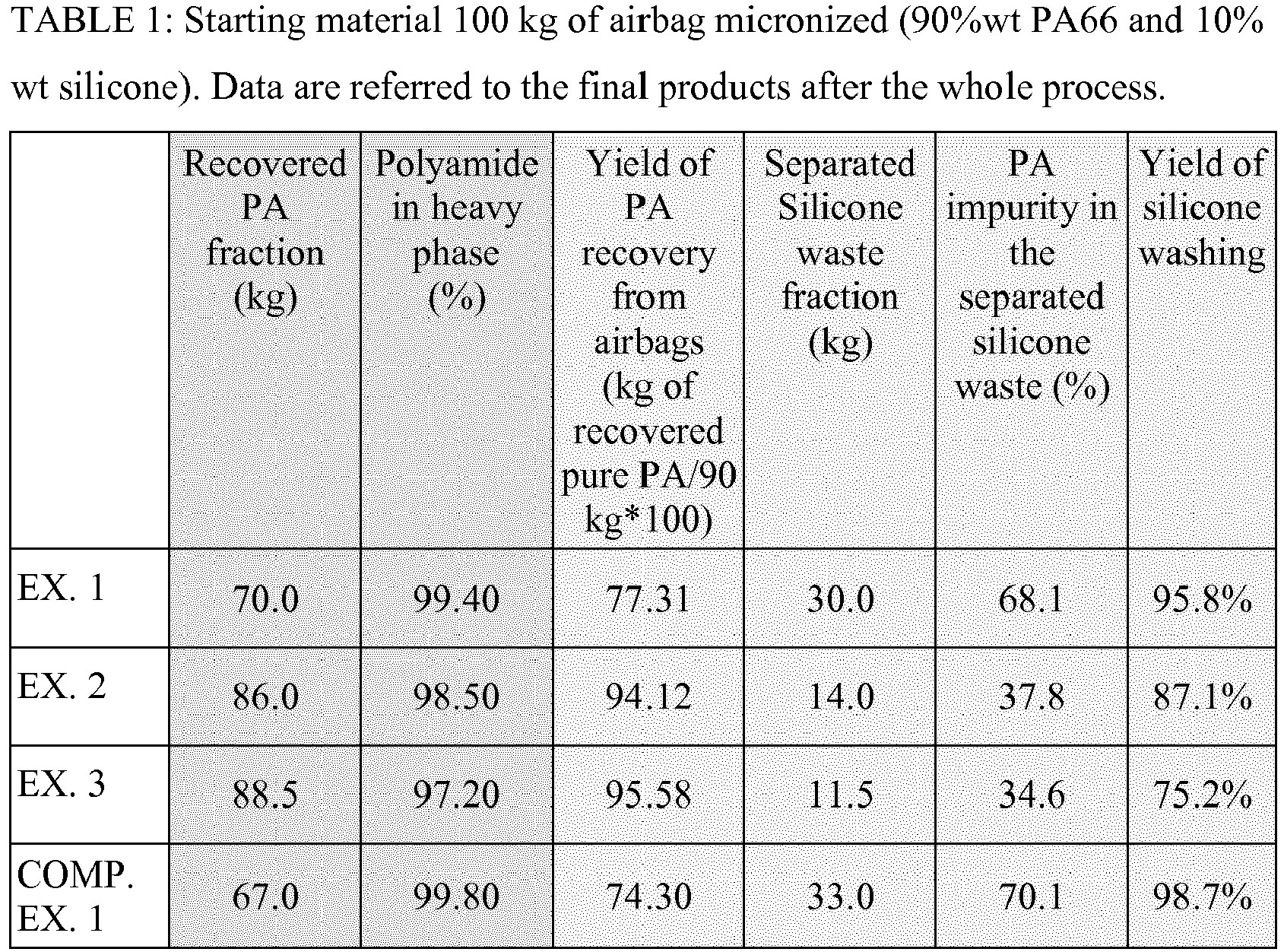
- The solid fractions present in the two exiting streams were then measured. The results are mentioned in table 1:
- The solid contents were determined by taking samples from the two exiting streams and drying at 170°C.
- The solid content of each of the outlet streams was defined by weighing difference.
- The yield of silicone washing and the yield of the Polyamide recovery were calculated by carrying out an elemental analysis of the silicon before the treatment on ground residues and after the treatment on the fibers forming the heavy solid phase.
- It is thus apparent that the process according to the present invention makes possible:
- the removal of the silicone coating from the textile
- the improvement of the yield on the Polyamide recovery from 74.3 to 94.12%
- The direct recovery of polyamide and silicone already neutralized from pH 14 to pH 9.2.
- This improvement of the yield of Polyamide recovery from previous patent N°
US 2014/0042252 A1 is made possible because there are a split of the chemical treatment and the separation phases allowing to adjust the liquid density before Solid / Solid / Liquid separator. Example 1 shows that even when using a non-optimal liquid density for separation, an acceptable yield of PA recovery can be achieved, which is still better than the yield of comparative example 1, where a more suitable density for separation was used. - The process parameters allowing improving the Polyamide recovery yield are mentioned in table 2.
TABLE 2: Slurry characteristic before S/S/L separation S/S/L separation parameters PA in heavy phase (%) Yield of PA recovery (%) pH liquid density Salt concentr ation Salt species speed bowl separator SSL T°C EX1 9,2 1.110 11.50% Na2SO4 3000 25 99.4 77.3% EX2 9,2 1.096 10.00% Na2SO4 3000 25 98.5 94.1% EX3 9,2 1.082 9.20% Na2SO4 3000 25 97.2 95.6% COMP. EX. 1 14 1.100 11.20% NaOH 3000 25 99.8 74.3% - In the case of example 1, 2, 3
The fibrous particles were subsequently rinsed with water, to regain a neutral pH (in the case of the comparative example) and to remove residual salt (in all cases).
Then, the fibrous particles were subsequently dried in a tunnel dryer with hot air, in order to reduce the moisture content to below 0.4%.
Claims (15)
- A process for treating an object comprising a first material and a second material bound to the first material, wherein the density of the first material is different from the density of the second material, said process comprising the following steps:(i) physically treating the object to obtain micronized particles,(ii) suspending the micronized particles in an acidic or alkaline solution to at least partially separate the first material from the second material,(iii) recovering the solids from the suspension obtained in step (ii) and suspending the recovered solids in a liquid having a density which is between the density of the first material and the density of the second material, and(iv) Separating the first material from the second material by applying a centrifugal force to the suspension obtained in step (iii).
- The process of claim 1, wherein the density of the first material (pA) and the density of the second material (pB) are such that they fulfil the following condition:

- The process of any one of the preceding claims, wherein the object comprises at least two layers.
- The process of any one of the preceding claims, wherein the first material is a thermoplastic polymer, preferably a polyamide.
- The process of any one of the preceding claims, wherein the second material is a material selected from the group consisting of silicones, polyurethanes and fluorinated polymers.
- The process of any one of the preceding claims, wherein step (i) further comprises cutting the object into pieces and then micronizing the pieces.
- The process of any one of the preceding claims, wherein the micronized particles obtained in step (i) have a particle size distribution characterized by a d50 value in the range from 15 microns to 5 mm.
- The process of any one of the preceding claims, wherein the micronized particles obtained in step (i) include particles substantially consisting of the first material, particles substantially consisting of the second material, and particles comprising the first material and the second material.
- The process of any one of the preceding claims, wherein the suspended particles are kept in the acidic or alkaline solution for at least 30 minutes.
- The process of any one of the preceding claims, wherein the acidic solution has a pH of at least 12.
- The process of any one of claims 1 to 9, wherein the alkaline solution has a pH of less than 3, preferably less than 2.
- The process of any one of the preceding claims, wherein the second material is a silicone, and step (ii) comprises suspending the micronized particles in a solution having a pH of at least 12.
- The process of any one of the preceding claims, wherein the suspension obtained in step (iii) and subjected to step (iv) has a pH in the range from 3 to 11, preferably from 4 to 10.
- The process of any one of the preceding claims, wherein step (iii) further comprises neutralizing the recovered solids and/or the suspension obtained in step (iii) prior to step (iv).
- The process of any one of the preceding claims, wherein the separated first material and/or the separated second material obtained from step (iv) is/are washed, dried and optionally shaped into granules or sinterized particles.
Priority Applications (10)
| Application Number | Priority Date | Filing Date | Title |
|---|---|---|---|
| EP17306923.8A EP3501775A1 (en) | 2017-12-22 | 2017-12-22 | Method of separating materials from an object |
| BR112020012258-0A BR112020012258A2 (en) | 2017-12-22 | 2018-12-20 | method for separating materials from an object |
| MX2020006550A MX2020006550A (en) | 2017-12-22 | 2018-12-20 | Method of separating materials from an object. |
| US16/956,985 US20210054162A1 (en) | 2017-12-22 | 2018-12-20 | Method of separating materials from an object |
| JP2020534307A JP2021506578A (en) | 2017-12-22 | 2018-12-20 | How to separate a material from an object |
| PL18822084.2T PL3727778T3 (en) | 2017-12-22 | 2018-12-20 | A method of separating materials from an object |
| KR1020207019203A KR20200101372A (en) | 2017-12-22 | 2018-12-20 | Methods of separating substances from objects |
| EP18822084.2A EP3727778B1 (en) | 2017-12-22 | 2018-12-20 | Method of separating materials from an object |
| PCT/EP2018/086227 WO2019122145A1 (en) | 2017-12-22 | 2018-12-20 | Method of separating materials from an object |
| CN201880082605.6A CN111542422A (en) | 2017-12-22 | 2018-12-20 | Method for separating material from object |
Applications Claiming Priority (1)
| Application Number | Priority Date | Filing Date | Title |
|---|---|---|---|
| EP17306923.8A EP3501775A1 (en) | 2017-12-22 | 2017-12-22 | Method of separating materials from an object |
Publications (1)
| Publication Number | Publication Date |
|---|---|
| EP3501775A1 true EP3501775A1 (en) | 2019-06-26 |
Family
ID=61007427
Family Applications (2)
| Application Number | Title | Priority Date | Filing Date |
|---|---|---|---|
| EP17306923.8A Withdrawn EP3501775A1 (en) | 2017-12-22 | 2017-12-22 | Method of separating materials from an object |
| EP18822084.2A Active EP3727778B1 (en) | 2017-12-22 | 2018-12-20 | Method of separating materials from an object |
Family Applications After (1)
| Application Number | Title | Priority Date | Filing Date |
|---|---|---|---|
| EP18822084.2A Active EP3727778B1 (en) | 2017-12-22 | 2018-12-20 | Method of separating materials from an object |
Country Status (9)
| Country | Link |
|---|---|
| US (1) | US20210054162A1 (en) |
| EP (2) | EP3501775A1 (en) |
| JP (1) | JP2021506578A (en) |
| KR (1) | KR20200101372A (en) |
| CN (1) | CN111542422A (en) |
| BR (1) | BR112020012258A2 (en) |
| MX (1) | MX2020006550A (en) |
| PL (1) | PL3727778T3 (en) |
| WO (1) | WO2019122145A1 (en) |
Cited By (3)
| Publication number | Priority date | Publication date | Assignee | Title |
|---|---|---|---|---|
| CN110587856A (en) * | 2019-09-19 | 2019-12-20 | 泉州师范学院 | Separation method of solar back panel film made of fluorine-containing material |
| IT201900023010A1 (en) * | 2019-12-04 | 2021-06-04 | Soluzioni Plastiche S R L | Process for recovering the plastic substrate from scraps of plastic sheets surface treated by means of a flocking process |
| EP3858571A1 (en) | 2020-01-30 | 2021-08-04 | Polytechnyl S.A.S. | Sustainable dry process for the separation and recovery of pure polymers from multi-material sources |
Families Citing this family (1)
| Publication number | Priority date | Publication date | Assignee | Title |
|---|---|---|---|---|
| WO2026068520A1 (en) * | 2024-09-25 | 2026-04-02 | Basf Se | Recycling of waste streams comprising polyamide and an organosilicon compound |
Citations (5)
| Publication number | Priority date | Publication date | Assignee | Title |
|---|---|---|---|---|
| WO1997040941A1 (en) | 1996-01-02 | 1997-11-06 | Noxon Ab | Decantation centrifuge |
| EP0950684A2 (en) * | 1998-04-17 | 1999-10-20 | F.A. Rueb Holding GmbH | Process for recycling a polyamide material which contains silicon resin |
| JP2001180413A (en) * | 1999-12-24 | 2001-07-03 | Takata Corp | How to remove silicon from airbag scrap cloth |
| JP2009269475A (en) * | 2008-05-08 | 2009-11-19 | Terabo Co Ltd | Silicone elimination method from airbag base cloth |
| US20140042252A1 (en) | 2011-03-31 | 2014-02-13 | Rhodia Operations | Process for the treatment of technical textiles |
Family Cites Families (6)
| Publication number | Priority date | Publication date | Assignee | Title |
|---|---|---|---|---|
| US5722603A (en) * | 1995-11-28 | 1998-03-03 | Alliedsignal Inc. /Dsm N.V. | Process for separation and recovery of waste carpet components |
| FR2907124B1 (en) * | 2006-10-13 | 2008-12-05 | Rhodia Recherches & Tech | PROCESS FOR TREATING AN ARTICLE COMPRISING A PLASTIC MATERIAL COVERED WITH A SILICONE MATERIAL |
| DE102008056311A1 (en) * | 2008-11-07 | 2010-05-12 | Apk Aluminium Und Kunststoffe Ag | Process for separating individual valuable substances from mixed, in particular comminuted plastic waste |
| FR2964108B1 (en) * | 2010-08-26 | 2013-10-04 | Rhodia Operations | RECYCLING OF INFLATABLE SAFETY CUSHIONS BASED ON POLYAMIDE |
| WO2012035673A1 (en) * | 2010-09-17 | 2012-03-22 | ユニチカ株式会社 | Polyamide resin composition, method for producing polyamide resin composition, and article obtained by forming polyamide resin composition |
| JP2014019003A (en) * | 2012-07-13 | 2014-02-03 | Fujimori Kogyo Co Ltd | Composite material separation and recovery method |
-
2017
- 2017-12-22 EP EP17306923.8A patent/EP3501775A1/en not_active Withdrawn
-
2018
- 2018-12-20 PL PL18822084.2T patent/PL3727778T3/en unknown
- 2018-12-20 WO PCT/EP2018/086227 patent/WO2019122145A1/en not_active Ceased
- 2018-12-20 KR KR1020207019203A patent/KR20200101372A/en not_active Withdrawn
- 2018-12-20 EP EP18822084.2A patent/EP3727778B1/en active Active
- 2018-12-20 CN CN201880082605.6A patent/CN111542422A/en active Pending
- 2018-12-20 US US16/956,985 patent/US20210054162A1/en not_active Abandoned
- 2018-12-20 JP JP2020534307A patent/JP2021506578A/en active Pending
- 2018-12-20 BR BR112020012258-0A patent/BR112020012258A2/en not_active Application Discontinuation
- 2018-12-20 MX MX2020006550A patent/MX2020006550A/en unknown
Patent Citations (5)
| Publication number | Priority date | Publication date | Assignee | Title |
|---|---|---|---|---|
| WO1997040941A1 (en) | 1996-01-02 | 1997-11-06 | Noxon Ab | Decantation centrifuge |
| EP0950684A2 (en) * | 1998-04-17 | 1999-10-20 | F.A. Rueb Holding GmbH | Process for recycling a polyamide material which contains silicon resin |
| JP2001180413A (en) * | 1999-12-24 | 2001-07-03 | Takata Corp | How to remove silicon from airbag scrap cloth |
| JP2009269475A (en) * | 2008-05-08 | 2009-11-19 | Terabo Co Ltd | Silicone elimination method from airbag base cloth |
| US20140042252A1 (en) | 2011-03-31 | 2014-02-13 | Rhodia Operations | Process for the treatment of technical textiles |
Cited By (5)
| Publication number | Priority date | Publication date | Assignee | Title |
|---|---|---|---|---|
| CN110587856A (en) * | 2019-09-19 | 2019-12-20 | 泉州师范学院 | Separation method of solar back panel film made of fluorine-containing material |
| CN110587856B (en) * | 2019-09-19 | 2021-07-27 | 泉州师范学院 | A kind of separation method of solar back sheet film containing fluorine material |
| IT201900023010A1 (en) * | 2019-12-04 | 2021-06-04 | Soluzioni Plastiche S R L | Process for recovering the plastic substrate from scraps of plastic sheets surface treated by means of a flocking process |
| EP3858571A1 (en) | 2020-01-30 | 2021-08-04 | Polytechnyl S.A.S. | Sustainable dry process for the separation and recovery of pure polymers from multi-material sources |
| WO2021152110A1 (en) | 2020-01-30 | 2021-08-05 | Polytechnyl Sas | Sustainable dry process for the separation and recovery of pure materials, particularly of pure polymers from multi-material sources |
Also Published As
| Publication number | Publication date |
|---|---|
| MX2020006550A (en) | 2021-01-08 |
| PL3727778T3 (en) | 2024-12-16 |
| EP3727778A1 (en) | 2020-10-28 |
| WO2019122145A1 (en) | 2019-06-27 |
| KR20200101372A (en) | 2020-08-27 |
| US20210054162A1 (en) | 2021-02-25 |
| BR112020012258A2 (en) | 2020-11-24 |
| CN111542422A (en) | 2020-08-14 |
| EP3727778B1 (en) | 2024-06-12 |
| JP2021506578A (en) | 2021-02-22 |
Similar Documents
| Publication | Publication Date | Title |
|---|---|---|
| EP3727778B1 (en) | Method of separating materials from an object | |
| JP6178782B2 (en) | Technical cloth treatment method | |
| US6172125B1 (en) | Process for recycling articles based on vinyl chloride polymers | |
| CA2251577C (en) | Process and device for the separation of viscoplastic materials such as plastics from materials such as paper which can be defibrated by mechanical action | |
| US9469049B2 (en) | Method and installation for separating individual valuable materials from mixed, in particular milled, plastic waste | |
| PL200695B1 (en) | Method for recycling vinyl polymer−based articles | |
| JP2009072569A (en) | Method for separating and cleaning surface yarn from carpet backing of used carpet and yarn products produced thereby | |
| WO2023180222A1 (en) | A mechanical polyolefin recycling process | |
| CZ2017446A3 (en) | A method of processing waste generated by recycling paper from used beverage cartons | |
| US9550872B2 (en) | Process for recovering nylon and polypropylene from a nylon fiber source | |
| TW202108831A (en) | Process and device for regenerating a solvent for cellulose from a spinning process | |
| US8338563B2 (en) | Method for purifying a plastic solution | |
| WO2013165755A1 (en) | Method for the preparation of highly purified recycled nylon | |
| JP2003507164A (en) | Method of removing paint from polymer material | |
| WO2021141750A1 (en) | Method for preparing a recycled rubber-based elastomer | |
| EP4096892B1 (en) | Sustainable dry process for the separation and recovery of pure materials, particularly of pure polymers from multi-material sources | |
| AU2023202776A1 (en) | Method for recylcing paint coated plastic waste | |
| CA3218109A1 (en) | Method for recycling plastic film |
Legal Events
| Date | Code | Title | Description |
|---|---|---|---|
| PUAI | Public reference made under article 153(3) epc to a published international application that has entered the european phase |
Free format text: ORIGINAL CODE: 0009012 |
|
| STAA | Information on the status of an ep patent application or granted ep patent |
Free format text: STATUS: THE APPLICATION HAS BEEN PUBLISHED |
|
| AK | Designated contracting states |
Kind code of ref document: A1 Designated state(s): AL AT BE BG CH CY CZ DE DK EE ES FI FR GB GR HR HU IE IS IT LI LT LU LV MC MK MT NL NO PL PT RO RS SE SI SK SM TR |
|
| AX | Request for extension of the european patent |
Extension state: BA ME |
|
| STAA | Information on the status of an ep patent application or granted ep patent |
Free format text: STATUS: THE APPLICATION IS DEEMED TO BE WITHDRAWN |
|
| 18D | Application deemed to be withdrawn |
Effective date: 20200103 |