EP3501761A1 - Robot, robot control system, robot control method, and program - Google Patents
Robot, robot control system, robot control method, and program Download PDFInfo
- Publication number
- EP3501761A1 EP3501761A1 EP18211410.8A EP18211410A EP3501761A1 EP 3501761 A1 EP3501761 A1 EP 3501761A1 EP 18211410 A EP18211410 A EP 18211410A EP 3501761 A1 EP3501761 A1 EP 3501761A1
- Authority
- EP
- European Patent Office
- Prior art keywords
- robot
- adornment
- perform
- controller
- image
- Prior art date
- Legal status (The legal status is an assumption and is not a legal conclusion. Google has not performed a legal analysis and makes no representation as to the accuracy of the status listed.)
- Granted
Links
Images






Classifications
-
- B—PERFORMING OPERATIONS; TRANSPORTING
- B25—HAND TOOLS; PORTABLE POWER-DRIVEN TOOLS; MANIPULATORS
- B25J—MANIPULATORS; CHAMBERS PROVIDED WITH MANIPULATION DEVICES
- B25J13/00—Controls for manipulators
- B25J13/08—Controls for manipulators by means of sensing devices, e.g. viewing or touching devices
-
- B—PERFORMING OPERATIONS; TRANSPORTING
- B25—HAND TOOLS; PORTABLE POWER-DRIVEN TOOLS; MANIPULATORS
- B25J—MANIPULATORS; CHAMBERS PROVIDED WITH MANIPULATION DEVICES
- B25J9/00—Program-controlled manipulators
- B25J9/16—Program controls
- B25J9/1694—Program controls characterised by use of sensors other than normal servo-feedback from position, speed or acceleration sensors, perception control, multi-sensor controlled systems, sensor fusion
- B25J9/1697—Vision controlled systems
-
- B—PERFORMING OPERATIONS; TRANSPORTING
- B25—HAND TOOLS; PORTABLE POWER-DRIVEN TOOLS; MANIPULATORS
- B25J—MANIPULATORS; CHAMBERS PROVIDED WITH MANIPULATION DEVICES
- B25J11/00—Manipulators not otherwise provided for
- B25J11/0005—Manipulators having means for high-level communication with users, e.g. speech generator, face recognition means
-
- B—PERFORMING OPERATIONS; TRANSPORTING
- B25—HAND TOOLS; PORTABLE POWER-DRIVEN TOOLS; MANIPULATORS
- B25J—MANIPULATORS; CHAMBERS PROVIDED WITH MANIPULATION DEVICES
- B25J11/00—Manipulators not otherwise provided for
- B25J11/003—Manipulators for entertainment
-
- B—PERFORMING OPERATIONS; TRANSPORTING
- B25—HAND TOOLS; PORTABLE POWER-DRIVEN TOOLS; MANIPULATORS
- B25J—MANIPULATORS; CHAMBERS PROVIDED WITH MANIPULATION DEVICES
- B25J13/00—Controls for manipulators
- B25J13/006—Controls for manipulators by means of a wireless system for controlling one or several manipulators
-
- B—PERFORMING OPERATIONS; TRANSPORTING
- B25—HAND TOOLS; PORTABLE POWER-DRIVEN TOOLS; MANIPULATORS
- B25J—MANIPULATORS; CHAMBERS PROVIDED WITH MANIPULATION DEVICES
- B25J19/00—Accessories fitted to manipulators, e.g. for monitoring, for viewing; Safety devices combined with or specially adapted for use in connection with manipulators
-
- B—PERFORMING OPERATIONS; TRANSPORTING
- B25—HAND TOOLS; PORTABLE POWER-DRIVEN TOOLS; MANIPULATORS
- B25J—MANIPULATORS; CHAMBERS PROVIDED WITH MANIPULATION DEVICES
- B25J19/00—Accessories fitted to manipulators, e.g. for monitoring, for viewing; Safety devices combined with or specially adapted for use in connection with manipulators
- B25J19/02—Sensing devices
- B25J19/021—Optical sensing devices
- B25J19/023—Optical sensing devices including video camera means
-
- B—PERFORMING OPERATIONS; TRANSPORTING
- B25—HAND TOOLS; PORTABLE POWER-DRIVEN TOOLS; MANIPULATORS
- B25J—MANIPULATORS; CHAMBERS PROVIDED WITH MANIPULATION DEVICES
- B25J9/00—Program-controlled manipulators
- B25J9/16—Program controls
- B25J9/1602—Program controls characterised by the control system, structure, architecture
Definitions
- This application relates generally to a robot, a robot control system, a robot control method, and a program.
- Robots are known that communicate with humans.
- Unexamined Japanese Patent Application Kokai Publication No. 2003-1582 describes a technique for removably dressing a walking robot with a costume. Applying an adornment such as a costume to a robot can create a sense of closeness to the robot and can enhance the entertainment based on appearance of the robot.
- an objective of the present disclosure is to provide a robot capable of enhancing entertainment, a robot control system, a robot control method, and a program.
- a robot according to an aspect of the present disclosure includes:
- a robot control system includes:
- a robot control method includes:
- a program according to an aspect of the present disclosure causes a computer of a robot to function as:
- FIG. 1 illustrates the appearance of a robot 100 according to Embodiment 1 of the present disclosure.
- the robot 100 has a shape resembling that of a human (child), and is a device that operates autonomously according to a predefined operation program.
- the robot 100 performs various operations in response to external stimulation, such as calls from and contact by a certain target that exists outside the robot 100.
- the robot 100 can communicate with the certain target and interact with the certain target.
- the certain target is an entity that exists outside the robot 100 and that communicates and interacts with the robot 100. Examples of the certain target include a user that is the owner of the robot 100, a human near the user (family, friend, or the like of the user), and an animal near the user (pet or the like owned by the user or the like).
- the certain target can also be referred to as a communication target, a communication partner, an interaction target, an interaction partner, or the like.
- the robot 100 has a three-dimensional shape with an appearance resembling a human (child).
- the robot 100 is fabricated using a hard synthetic resin such as plastic, for example, as the main material.
- the robot 100 includes a head 101, a body 102, eyes 104, a mouth 105, hand portions 107, and feet 108.
- the head 101, the hands 107, and the feet 108 are parts that can be moved by drive members installed in the robot 100.
- the head 101 is attached to the body 102 by a neck joint so as to be rotatable in the three directions of pitch, roll, and yaw.
- the neck joint is provided on the neck.
- the eyes 104 are provided with a display 117 that displays an image related to the eyes (eyeballs or the like).
- the mouth 105 is provided with an imager 115a that images the space in front of the robot 100.
- FIG. 2 illustrates the hardware configuration of the robot 100.
- the robot 100 includes a controller (central processing unit) 110, a storage unit 111, a battery 112, a driving driver 113, movable parts 114, a sensor section 115, a wireless communicator 116, a display 117, a speech outputter 118, and an image recognizer 119.
- the controller 110 includes a central processing unit (CPU), read only memory (ROM), and random access memory (RAM).
- the CPU is a microprocessor or the like and is a central processing unit that executes a variety of processing and computation.
- the CPU reads out a control program stored in the ROM and controls the operation of the entire robot 100 while using the RAM as working memory.
- the storage unit 111 is nonvolatile memory such as flash memory or a hard disk.
- the storage unit 111 stores an operating system (OS), application programs, and other programs and data used by the controller 110 to perform the various processes.
- OS operating system
- application programs application programs
- other programs and data used by the controller 110 to perform the various processes.
- the storage unit 111 stores data generated or acquired as a result of the controller 110 performing the various processes.
- the battery 112 is a storage battery that stores electrical energy and supplies power to the various components of the robot 100. When the robot 100 has returned to the charging station, the battery 112 is charged by the charging station.
- the driving driver 113 includes the drive members such as a motors and actuators that drive the movable parts 114 of the robot 100, and drive circuits that drive these drive members.
- the movable parts 114 are parts that can move, specifically the head 101, the hands 107, and the feet 108.
- the controller 110 sends control signals to the drive circuits on the basis of the operation program.
- the drive circuits provide driving pulse signals to the drive members in accordance with the control signals sent from the controller 110.
- the drive members drive the movable parts 114 in accordance with the pulse signals provided from the drive circuits.
- the driving driver 113 drives the movable parts 114, thereby causing the robot 100 to perform various operations. For example, by moving the feet 108, the robot 100 can be moved forward or backward, or the direction of the robot 100 can be changed. Additionally, by moving the head 101 or the hands 107, the robot 100 can imitate human operations and human gestures.
- the sensor section 115 includes a plurality of sensors that detect physical quantities around or inside the robot 100. As illustrated in FIG. 2 , the sensor section 115 includes an imager 115a that captures an image of the surroundings of the robot 100, a sound sensor 115b that detects sound, a contact sensor 115c that detects contact with the robot 100, and a distance sensor 115d that measures distances to surrounding objects.
- the sensor section 115 includes an acceleration sensor that detects movement of the robot 100, a gyro sensor that detects rotation of the robot 100, a geomagnetic sensor that detects the orientation of the robot 100, a temperature sensor that detects the temperature of the surroundings of the robot 100, an atmospheric pressure sensor that detects the atmospheric pressure of the surroundings of the robot 100, and the like.
- the imager 115a is a so-called camera, and is installed in the mouth 105.
- the imager 115a includes an image acquirer that acquires an image of a target by collecting light reflected from the target and an image processor that processes the image acquired by the image acquirer.
- the imager 115a functions as imaging means (robot-side imaging means) that captures an image of the space in front of the robot 100.
- the sound sensor 115b is installed in the head 101 and detects speech uttered by the certain target, ambient environmental sounds, and the like. While not illustrated in the drawings, the robot 100 includes, as the sound sensor 115b, a plurality of microphones arranged surrounding the head 101. This configuration enables the efficient detection of sounds generated from all directions. Other sensors are installed at various locations of the robot 100.
- the robot 100 acquires information indicating the surrounding state and the internal state of the robot 100 via these sensors.
- the sensor section 115 acquires information indicating the surrounding state and the internal state of the robot 100 via this plurality of sensors and supplies
- the wireless communicator 116 includes an interface for wirelessly communicating with external devices. Under the control of the controller 110, the wireless communicator 116 wirelessly communicates with external devices, including the charging station, in accordance with a communication standard such as Wireless Fidelity (Wi-Fi) or a similar wireless local area network (LAN), Bluetooth (registered trademark), or Near Field Communication (NFC).
- a communication standard such as Wireless Fidelity (Wi-Fi) or a similar wireless local area network (LAN), Bluetooth (registered trademark), or Near Field Communication (NFC).
- the display 117 is a display device such as a liquid crystal display, an organic electro luminescence (EL) display, or a light emitting diode (LED).
- the display 117 is installed in the eyeball portions of the eyes 104 and, under the control by a display drive circuit (not illustrated in the drawings), displays various images according to the situation.
- the speech outputter 118 includes a speaker and a speech output interface.
- the speech outputter 118 converts speech data generated by the controller 110 to speech, and outputs this speech out of the robot 100.
- the speaker is installed in the head 101.
- the speech outputter 118 outputs various types of speech including animal sounds and human language.
- the robot 100 collects the speech of the certain target via the sound sensor 115b, and outputs, from the speech outputter 118, speech corresponding to the utterance content of the certain target. As a result, the robot 100 is capable of simple conversation with the certain target.
- the image recognizer 119 includes a processor for image processing such as a digital signal processor (DSP) or a graphics processing unit (GPU), and buffer memory that temporarily saves images to be processed.
- DSP digital signal processor
- GPU graphics processing unit
- the image recognizer 119 recognizes the images captured by the imager 115a.
- the image recognizer 119 uses well-known image recognition techniques to recognize people, faces, objects, patterns, and the like included in the images captured by the imager 115a.
- the image recognizer 119 recognizes the face of the certain target captured by the imager 115a.
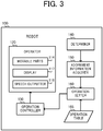
- the robot 100 functionally includes an operator 120, an operation controller 130, a determiner 140, an adornment information acquirer 150, and an operation setter 160.
- the CPU performs control to read the program stored in the ROM out to the RAM and execute that program.
- the CPU functions as the various components, namely the operation controller 130, the determiner 140, the adornment information acquirer 150, and the operation setter 160.
- the operator 120 is a component that causes the robot 100 to perform operations. Specifically, the operator 120 includes the movable parts 114, the display 117, and the speech outputter 118, and causes the robot 100 to perform operations by moving the movable parts 114, displaying an image on the display 117, or outputting speech from the speech outputter 118.
- the operator 120 functions as operation means.
- the operation controller 130 controls the operator 120 to cause the robot 100 to perform various predefined operations.
- the operation controller 130 changes the position, direction, posture, or the like of the robot 100 by moving the movable parts 114 including the feet 108.
- the operation controller 130 changes the facial expression of the robot 100 by displaying an image on the display 117.
- the operation controller 130 causes the robot 100 to converse with the certain target by outputting speech from the speech outputter 118.
- the operation controller 130 is realized by cooperation between the controller 110, the driving driver 113, the movable parts 114, the display 117, and the speech outputter 118.
- the operation controller 130 functions as operation control means.
- the determiner 140 determines whether an adornment is applied to the robot.
- the term "adornment” refers to a costume, an accessory, eyeglasses, a watch, or the like, and is an article (part) that is attached as an add-on to the exterior of the robot 100.
- the determiner 140 determines whether the user, for example, has attached such an adornment to the robot 100.
- the determiner 140 determines, on the basis of a captured image in which the robot 100 is captured, whether an adornment is applied to the robot.
- FIG. 4 illustrates a situation in which an image of the robot 100, wearing a hat 211 as an adornment, is captured.
- FIG. 5 illustrates a captured image 200 of the robot 100 obtained as a result of the image capturing.
- the user when the user applies some sort of adornment to the robot 100, the user captures an image of the appearance of the robot 100 using a communication terminal 250.
- the communication terminal 250 is a device that is provided with an imager (communication terminal-side imager), such as a smartphone, a mobile phone, a digital camera, or the like.
- an imager communication terminal-side imager
- the captured image 200 obtained by the image capturing is sent from the communication terminal 250 to the robot 100.
- the determiner 140 acquires, via the wireless communicator 116, the captured image 200 sent from the communication terminal 250.
- the captured image 200 may be sent directly from the communication terminal 250 to the robot 100, or may be sent indirectly to the robot 100 via another device such as the charging station, a server, or the like.
- the determiner 140 determines whether an adornment is applied to the robot 100 by comparing the acquired captured image 200 with a reference image.
- the reference image is an image that serves as a reference of the default appearance of the robot 100, and depicts an appearance of the robot 100 in a state that is free of any adornments.
- the determiner 140 recognizes, via the functions of the image recognizer 119, the robot 100 captured in the captured image 200. Then, when there is a difference between the appearance of the recognized robot 100 and the appearance of the robot 100 depicted in the reference image, the determiner 140 determines that an adornment is applied to the robot 100.
- the determiner 140 is realized by cooperation between the controller 110, the communication unit 116, and the image recognizer 119.
- the determiner 140 functions as determination means.
- the adornment information acquirer 150 acquires adornment information indicating that adornment.
- the adornment information is information that identifies the adornment that is applied to the robot 100.
- the adornment information acquirer 150 acquires the adornment information on the basis of the captured image 200 in which the robot 100 is captured.
- the determiner 140 determines that an adornment is applied to the robot 100
- the adornment information acquirer 150 acquires the difference between the robot 100 captured in the captured image 200 and the robot 100 depicted in the reference image. Then, the determiner 140 identifies, by an object recognition technique, an object corresponding to the acquired difference.
- the adornment information acquirer 150 acquires adornment information indicating that the adornment applied to the robot 100 is the hat 211.
- the adornment information acquirer 150 acquires adornment information indicating that the adornment applied to the robot 100 is a costume.
- the adornment information acquirer 150 is realized by cooperation between the controller 110 and the image recognizer 119.
- the adornment information acquirer 150 functions as adornment information acquisition means.
- the operation setter 160 sets, according to the adornment information acquired by the adornment information acquirer 150, an operation to be performed by the operator 120. Specifically, the operation setter 160 references a predefined operation table 165.
- the operation table 165 is a table that defines operations (hereinafter referred to as "adornment operations") corresponding to adornments applied to the robot 100.
- the operation table 165 is stored in advance in the storage unit 111.
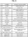
- FIG. 6 illustrates a specific example of the operation table 165.
- each adornment applied to the robot 100 is associated with the content of an adornment operation that the robot 100, to which that adornment is applied, is caused to perform.
- the operation setter 160 changes the travel route of the robot 100 to a route with looser height restrictions so that the hat does not strike any obstacles when the robot 100 moves.
- the operation setter 160 narrows the range of motion of the head 101, the hands 107, and the feet 108, thereby slowing down the movement of the robot 100.
- the operation setter 160 When sunglasses are applied as the adornment, the operation setter 160 lowers the brightness of the display 117, thereby suppressing the power consumption of the eyes 104. Additionally, when the sunglasses are not applied, the operation setter 160 changes the travel route of the robot 100 so as to avoid sunny routes more than when the sunglasses are applied. (4) When eyeglasses are applied as the adornment, the operation setter 160 sets a gesture of adjusting the eyeglasses using the hands 107. (5) When a wristwatch is applied as the adornment, the operation setter 160 sets a gesture of looking at the wristwatch. In addition, when a camera, a skirt, or the like is applied as the adornment such as in (6) to (12) illustrated in FIG. 6 , the operation setter 160 sets the adornment operation such that a function or a skill using that adornment is demonstrated.
- the operation setter 160 sets the operation according to the plurality of adornments. For example, (13) When a brush and a painter hat are applied, the operation setter 160 sets the operation of the robot 100 such that the robot 100 draws more skillfully than when only the brush is applied. (14) When presentation notes and a laser pointer or a pointing stick are applied, the operation setter 160 sets the operation of the robot 100 so as to deliver a presentation using the laser pointer or the pointing stick.
- the operation setter 160 may set the operation according to the location where the adornment is performed. For example, (15) when a brush is applied to the dominant hand as the adornment, the operation setter 160 sets the operation of the robot 100 such that the robot 100 draws more skillfully than when the brush is applied to the non-dominant hand. (16) When a ribbon is applied to the head as the adornment, the operation setter 160 recognizes the ribbon as a hair ornament and sets the operation of the robot 100 such that the robot 100 behaves like a girl. (17) When a ribbon is applied to the neck as the adornment, the operation setter 160 recognizes the ribbon as a necktie and sets the operation of the robot 100 such that the robot 100 behaves like a boy.
- the operation setter 160 sets various operations according to the adornment applied to the robot 100.
- the operation setter 160 is realized by cooperation between the controller 110 and the storage unit 111.
- the operation controller 130 controls the operator 120 to cause the robot 100 to perform the set operation. In other words, when an adornment is applied to the robot 100, the operation controller 130 controls the operator 120 to perform the adornment operation corresponding to that adornment.
- the operation controller 130 narrows the range of motion of the hands 107, as illustrated in FIG. 7 .
- the operation controller 130 controls the operation of the hands 107 such that the motion of the hands 107 in the directions indicated by the arrows in FIG. 7 is smaller than when the costume 212 is not applied.
- the operation controller 130 causes a hand 107 to move to the head 101 as illustrated in FIG. 8 to perform a gesture of adjusting the eyeglasses 213.
- the operation controller 130 causes the robot 100 to perform the various operations defined in FIG. 6 by driving the head 101, the hands 107, and the feet 108, displaying an image on the display 117, or outputting speech from the speech outputter 118. Since the robot 100 performs a variety of operations according to the adornments, the user can be entertained.
- the robot control processing illustrated in FIG. 9 is started when the robot 100 is placed in a normal operable state.
- the normal operable state is defined by the power supply of the robot 100 being turned ON and the battery 112 being charged.
- the controller 110 When the robot control processing starts, the controller 110 functions as the operation controller 130 and causes the operator 120 to execute a normal operation (step S1).
- the phrase "normal operation” refers to an operation under normal conditions that is unrelated to whether an adornment is applied to the robot 100.
- the controller 110 changes the position, direction, posture, or the like of the robot 100 by moving the movable parts 114.
- the controller 110 displays an image on the display 117 and outputs speech from the speech outputter 118.
- the controller 110 causes the robot 100 to perform behavior typical of a robot by causing the operator 120 to execute various predefined operations.
- the controller 110 functions as the determiner 140 and determines whether an adornment is applied to the robot 100 (step S2). Specifically, the controller 110 acquires the captured image 200 obtained as a result of the user imaging the robot 100, and determines whether an adornment is applied to the robot 100 by comparing the acquired captured image 200 with the reference image.
- step S2 determines that an adornment is not applied to the robot 100 (step S2; NO)
- the controller 110 remains at step S1 and continues to cause the operator 120 to execute the normal operation.
- the controller 110 determines that an adornment is applied to the robot 100 (step S2; YES)
- the controller 110 functions as the adornment information acquirer 150 and acquires the adornment information indicating the adornment applied to the robot 100 (step S3).
- the controller 110 performs object recognition on the difference between the captured image 200 of the robot 100 and the reference image.
- the controller 110 identifies if the adornment applied to the robot 100 is, for example, the hat 211, the costume 212, the eyeglasses 213, or the like.
- the controller 110 When the controller 110 acquires the adornment information, the controller 110 functions as the operation setter 160 and sets the adornment operation corresponding to the adornment applied to the robot 100 (step S4). Specifically, the controller 110 references the operation table illustrated in FIG. 6 , identifies the operation corresponding to the adornment applied to the robot 100, and sets the identified operation as the operation to be performed by the robot 100.
- the controller 110 When the controller 110 sets the adornment operation, the controller 110 functions as the operation controller 130 and causes the robot 100 to perform the set operation (step S5). Specifically, the controller 110 controls the movable parts 114, the display 117, or the speech outputter 118 and causes the robot 100 to perform the operation corresponding to the adornment, such as illustrated in FIG. 7 or FIG. 8 .
- the controller 110 When the robot 100 is caused to perform the adornment operation, the controller 110 returns to the processing of step S1 and repeats the processing of steps S1 to S5. In other words, each time an adornment is applied to the robot 100 while the robot 100 is performing the normal operation, the controller 110 repeats the processing that causes the robot 100 to perform the operation corresponding to that adornment.
- the robot 100 determines whether an adornment is applied to the robot 100 and, when it is determined that an adornment is applied to the robot 100, performs an operation corresponding to that adornment.
- the robot 100 performs various operations in response to the adornments applied to the robot 100.
- the entertainment of the robot 100 can be enhanced.
- the determiner 140 determines, on the basis of the captured image 200 that is captured by the user, whether an adornment is applied to the robot 100.
- the determiner 140 may use the contact sensor 115c or a switch to determine whether an adornment is applied to the robot 100.
- the contact sensor 115c or the switch is disposed at a plurality of locations where adornments may be applied to the robot 100, and attachable locations are predetermined on the basis of the type of adornment.
- the adornment is applied to the head 101; if the adornment is the costume 212, the adornment is applied to the body 102; and if the adornment is the eyeglasses 213, the adornment is applied to the eyes 104. Additionally, in this case, when contact by the contact sensor 115c is detected at one of the locations or pressing by the switch is detected at one of the locations, the determiner 140 determines that an adornment is applied.
- the adornment information acquirer 150 acquires the adornment information indicating if the adornment is, for example, the hat 211, the contact sensor 115c, or the eyeglasses 213.
- an integrated circuit (IC) tag is embedded in the adornment in advance, and the determiner 140 determines whether the adornment is applied to the robot 100 by wireless communication such as NFC using the IC tag. Specifically, when an adornment is applied to the robot 100, the determiner 140 receives, via the function of the wireless communicator 116, a wireless signal emitted from the IC tag embedded in that adornment. When the determiner 140 receives the wireless signal from the IC tag, the determiner 140 determines that the adornment is applied to the robot 100. Additionally, identification information for identifying the adornment is included in the wireless signal emitted from the IC tag.
- IC integrated circuit
- the adornment information acquirer 150 acquires, on the basis of this identification information, the adornment information indicating if the adornment applied to the robot 100 is, for example, the hat 211, the contact sensor 115c, or the eyeglasses 213.
- Embodiment 2 of the present disclosure will be described.
- descriptions of configurations and functions that are the same as described in Embodiment 1 are forgone.
- the robot 100 according to Embodiment 1 determines whether an adornment is applied to the robot 100 and acquires the adornment information on the basis of the captured image 200 captured by the user.
- the robot 100 according to Embodiment 2 acquires the captured image 200 by using a mirror provided on the charging station to image the appearance of the robot 100.
- the robot 100 according to Embodiment 2 is described below.
- FIG. 10 illustrates a robot control system 300 according to Embodiment 2.
- the robot control system 300 includes the robot 100 and a charging station 310.
- the robot 100 has the same configuration as described in Embodiment 1.
- the charging station 310 is equipment for charging the robot 100.
- the charging station 310 is installed at an appropriate location such that the robot 100 can autonomously move (return) to the charging station 310. Examples of the appropriate location include a location in the same room as the robot 100.
- the charging station 310 includes a mirror 312 on an upper portion and a stand 311 on a lower portion.
- the stand 311 includes a columnar support that supports the mirror 312 and a plate-like bottom on which the robot 100 is placed.
- the charging station 310 includes, as components related to control, a controller 320, a storage unit 321, a communicator 322, a power supply 323, and a charger 324.
- the controller 320 includes a CPU, ROM, and RAM.
- the CPU is a microprocessor or the like and is a central processing unit that executes a variety of processing and computation.
- the CPU reads out a control program stored in the ROM and controls the operation of the entire charging station 310 while using the RAM as working memory.
- the storage unit 321 is nonvolatile memory such as flash memory or a hard disk.
- the storage unit 321 stores programs and data used by the controller 320 to perform various processes. Moreover, the storage unit 321 stores data generated or acquired as a result of the controller 320 performing the various processes.
- the communicator 322 includes an interface for performing wired or wireless communication with external devices. Under the control of the controller 320, the communicator 322 wirelessly communicates with the robot 100 in accordance with a communication standard such as Wi-Fi or a similar wireless LAN, or Bluetooth (registered trademark).
- a communication standard such as Wi-Fi or a similar wireless LAN, or Bluetooth (registered trademark).
- the power supply 323 includes a power supply circuit, and produces and supplies the necessary power to the various components of the charging station 310.
- the charger 324 includes a charging circuit and charges the battery 112 of the robot 100.
- the charger 324 is provided at the bottom of the stand 311. When the robot 100 has returned to the charging station 310, the robot 100 stays on top of the charger 324. Electrodes that receive charging from the charger 324 are provided on the bottom surfaces of the feet 108 of the robot 100. The charger 324 supplies power generated by the power supply 323 to the robot 100 via the electrodes on the feet 108, thereby charging the battery 112 of the robot 100 that has returned to the charging station 310.
- the mirror 312 includes a mirror surface that reflects visible light.
- the mirror surface is provided at a position facing the robot 100 that has returned to the charging station 310.
- the front of the robot 100 faces the mirror 312 while the robot 100 is being charged by the charger 324. In this state, the mirror surface of the mirror 312 is within the imaging range (the area defined by the dashed lines in FIG. 10 ) of the imager 115a of the robot 100.
- the area defined by the dash-dot lines in FIG. 10 appears in the mirror surface of the mirror 312 as a mirror image.
- the shape, dimensions, and installation location of the mirror surface of the mirror 312 are determined such that the entire robot 100 is included, as a mirror image, within the imaging range of the imager 115a of the robot 100 during charging.
- the location of the charging station 310 is stored in advance in the storage unit 111.
- the robot 100 drives the movable parts 114 and moves the robot 100 to the location of the charging station 310 in order to charge the battery 112.
- the predetermined charging condition is a predetermined condition for charging the robot 100. Specifically, the predetermined charging condition is satisfied when an amount of charge of the battery 112 is below a specified value, or when a predefined periodic timing arrives. Charging by the charger 324 starts when the charging condition is satisfied and the robot 100 is positioned at the charging station 310. When the charging starts, the imager 115a captures, via the mirror 312, the appearance of the robot 100 being charged, thereby acquiring the captured image 200.
- the determiner 140 determines, on the basis of the captured image 200 of the robot 100 that is obtained by the imager 115a, whether an adornment is applied to the robot 100. Specifically, upon the acquisition of the captured image 200 of the robot 100 by the imager 115a, the determiner 140 determines whether an adornment is applied to the robot 100 by comparing the captured image 200 with the reference image, as in Embodiment 1.
- the adornment information acquirer 150 acquires the adornment information indicating that adornment. Specifically, the adornment information acquirer 150 uses the image recognizer 119 to identify the difference between the captured image 200 and the reference image, thereby discerning whether the adornment applied to the robot 100 is, for example, the hat 211, the costume 212, or the eyeglasses 213.
- the operation setter 160 sets, according to the adornment information acquired by the adornment information acquirer 150, an operation to be performed by the operator 120.
- the operation controller 130 controls the operator 120 to perform the operation set by the operation setter 160. The functions of these components are the same as described in Embodiment 1.
- the robot 100 according to Embodiment 2 determines and identifies the adornment applied to the robot 100 by imaging the appearance of the robot 100 using the mirror 312 of the charging station 310 while the robot 100 is being charged by the charging station 310. Since the robot 100 according to Embodiment 2 captures an image of the appearance of the robot 100 using the mirror 312, the need for imaging the robot 100 by an external device such as the communication terminal 250 in Embodiment 1 is eliminated. As such, with the robot 100 that performs various operations corresponding to adornments, less effort is needed to determine and identify the adornment that is applied to the robot 100.
- the charging station 310 includes the mirror 312.
- the mirror 312 may be provided at a location other than the charging station 310.
- a typical mirror used as furniture may be used as the mirror 312 for imaging the appearance of the robot 100.
- the location of the mirror 312 is stored in advance in the storage unit 111, and the operation controller 130 controls the operator 120 to move the robot 100 to the location where the mirror is provided at a predetermined periodic timing, for example. Then, when the operation controller 130 has controlled the operator 120 to move the robot 100 in front of the mirror 312, the imager 115a captures an image of the robot 100 via the mirror 312, thereby acquiring the captured image 200.
- a configuration is possible in which the robot 100 captures an image of the appearance of the robot 100 by the imager 115a of the robot 100, without using the mirror 312.
- the robot 100 can capture an image of the appearance of the robot 100 by extending that hand 107 and directing the imaging range of the imager 115a toward the robot 100.
- the captured image 200 in which the robot 100 is captured can be acquired without using the mirror 312.
- a charging station 310a includes an imager 330 that captures an image of the robot 100.
- the charging station 310a includes the imager 330 at the location where the mirror 312 is provided in FIG. 10 .
- the imager 330 functions as station-side imaging means and captures the area defined by the dashed lines in FIG. 12 as the imaging range.
- the imager 330 acquires the captured image 200 in which the appearance of the robot 100 being charged by the charger 324 is depicted.
- the controller 320 cooperates with the communicator 322 to function as transmission means, and sends the captured image 200 captured by the imager 330 to the robot 100.
- the controller 110 cooperates with the wireless communicator 116 to function as receiving means, and receives the captured image 200 sent from the charging station 310a. Then, the determiner 140 determines, on the basis of the received captured image 200, whether an adornment is applied to the robot 100. When the determiner 140 determines that an adornment is applied to the robot 100, the adornment information acquirer 150 acquires the adornment information indicating that adornment. Thus, since the charging station 310a includes the imager 330, it is possible to capture an image of the appearance of the robot 100 without using a mirror and determine whether an adornment is applied to the robot 100.
- Embodiment 3 of the present disclosure will be described.
- descriptions of configurations and functions that are the same as described in Embodiment 1 or 2 are forgone.
- FIG. 13 illustrates the functional configuration of a robot 100a according to Embodiment 3.
- the robot 100a according to Embodiment 3 functionally includes an operator 120, an operation controller 130, a determiner 140, an adornment information acquirer 150, and an operation setter 160. These components function in the same manner as the components described in Embodiment 1 or 2.
- the robot 100a according to Embodiment 3 includes a presence detector 170, an action detector 180, and a reaction acquirer 190.
- the CPU performs control and reads the program stored in the ROM out to the RAM and executes that program, thereby functioning as the various components described above.
- the presence detector 170 detects the presence of the certain target, namely the user or the like, that is present outside the robot 100a. Specifically, the presence detector 170 uses the imager 115a to capture an image of the surroundings of the robot 100a, thereby acquiring an image representing the state of the surroundings of the robot 100a. Then, using the image recognizer 119, the presence detector 170 recognizes the image acquired by the imager 115a and determines wither a human or an animal is captured in the image. Thus, the presence detector 170 is realized by cooperation between the controller 110, the imager 115a, and the image recognizer 119.
- the action detector 180 detects an action that the certain target performs on the robot 100a.
- an action that the certain target performs on the robot 100a refers to an action such as conversing or contacting performed by the certain target for the purpose of interacting (communicating) with the robot 100.
- Examples of actions that the certain target performs on the robot 100a include calling out to the robot 100a, contacting the surface of the robot 100a, or demonstrating a gesture to the robot 100a.
- the action detector 180 detects such actions performed by the certain target using the various sensors of the sensor section 115.
- the action detector 180 detects, via the sound sensor 115b, the speech uttered by the certain target. In a case in which the certain target contacts the robot 100a, the action detector 180 detects the contact via the contact sensor 115c. In a case in which the certain target demonstrates a gesture to the robot 100a, the action detector 180 detects the gesture via the imager 115a.
- the action detector 180 is realized by cooperation between the controller 110 and the various sensors of the sensor section 115.
- the action detector 180 functions as action detection means.
- the operation controller 130 controls the operator 120 to perform an interaction operation for responding to the detected action.
- the interaction operation is an operation whereby the robot 100a interacts (communicates) with the certain target, and is also called a "response operation” or a “response action”.
- the operation controller 130 when the action detector 180 detects speech, a contact, a gesture, or the like of the certain target, the operation controller 130 performs the interaction operation by moving the head 101 to face the certain target or moving the feet 108 to move toward the certain target. Alternatively, the operation controller 130 may perform the interaction operation by displaying an image on the display 117 or outputting speech from the speech outputter 118. Thus, the operation controller 130 causes the robot 100a to perform various operations as the interaction operation in response to the actions of the certain target detected by the action detector 180. As a result, the certain target can enjoy communication with the robot 100a.
- the operation controller 130 controls the operator 120 to perform a solo operation, which differs from the interaction operation.
- the solo operation is an operation that the robot 100a performs alone, independent of the certain target, and is a spontaneous operation that does not involve interaction (communication) with the certain target.
- the solo operation is also called "acting alone” or “playing alone.”
- the operation controller 130 causes the robot 100a to perform the interaction operation.
- the operation controller 130 causes the robot 100a to perform the solo operation.
- the robot can be caused to perform natural operations that imitate a real person (child), and the sense of closeness with the robot 100a can be enhanced.
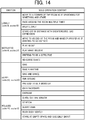
- FIG. 14 illustrates examples of the solo operation.
- the operation controller 130 causes the robot 100a to perform one of the solo operations illustrated in FIG. 14 .
- the operation controller 130 causes the robot 100a to perform different solo operations according to the emotion of the robot 100a.
- the robot 100a displays four emotions in terms of two emotion values, namely "calm” and “excite.” These four emotions are “lonely”, “motivated”, “happy”, and “relaxed.”
- the operation controller 130 switches between the two emotion values, thereby changing the emotion of the robot 100a.
- the operation controller 130 causes the robot 100a to perform a solo operation such as "Move to a corner of the room as if searching for something and stare.”
- the operation controller 130 causes the robot 100a to perform a solo operation such as "Move to an end of the room and wander around as if wanting to go outside.”
- the operation controller 130 causes the robot 100a to perform a solo operation such as "Sing.”
- the operation controller 130 causes the robot 100a to perform a solo operation such as "Stare out the window.”
- the solo operation to be performed is selected randomly from among the plurality of solo operations available for each emotion.
- the solo operations of the robot 100a may include the adornment operations illustrated in FIG. 6 of Embodiment 1.
- the operation controller 130 causes the robot 100a to perform solo operations on the basis of the surrounding environment of the robot 100a or the time.
- the surrounding environment of the robot 100a is information outside of the robot 100a such as the sound level, the temperature, the atmospheric pressure, the brightness, and obstacles.
- the surrounding environment is detected by the various sensors of the sensor section 115.
- the time is information such as the current time, the date, and the season. For example, when a predetermined condition related to the environment such as "The robot 100a hears music via the sound sensor 115b" or "The robot 100a hear a conversation between people via the sound sensor 115b" is satisfied, the operation controller 130 causes the robot 100a to perform the corresponding solo operation.
- the operation controller 130 causes the robot 100a to perform the corresponding solo operation.
- the interaction operation and the solo operation are predefined as a part of the operation table 165 stored in the storage unit 111.
- the operation setter 160 references the operation table 165 and sets the interaction operation or the solo operation that the robot 100a will be caused to perform. Then, the operation controller 130 causes the robot 100a to perform the interaction operation or the solo operation set by the operation setter 160.
- the reaction acquirer 190 acquires a reaction of the certain target to the first operation.
- the operation controller 130 controls the operator 120 to perform a first operation as the adornment operation while the robot 100a is performing the interaction operation.
- the operation controller 130 causes the robot 100a to perform the interaction operation.
- the operation controller 130 controls the operator 120 and causes the robot 100a to perform one of the operations illustrated in FIG. 6 , for example.
- the reaction acquirer 190 acquires the reaction of the certain target to that operation.
- the reaction acquirer 190 acquires the reaction of the certain target by detecting speech uttered by the certain target, contact to the robot 100a by the certain target, or a gesture of the certain target. For example, when the certain target utters speech, the reaction acquirer 190 detects the speech via the sound sensor 115b. When the certain target contacts the robot 100a, the reaction acquirer 190 detects the contact via the contact sensor 115c. When the certain target displays a gesture, the reaction acquirer 190 detects the gesture via the imager 115a. Thus, the reaction acquirer 190 is realized by cooperation between the controller 110 and the various sensors of the sensor section 115. The reaction acquirer 190 functions as reaction acquisition means.
- the operation controller 130 controls the operator 120 to perform a second operation according to the reaction acquired by the reaction acquirer 190.
- the second operation is different from the first operation.
- the first operation is an operation that is performed in accordance with the adornment applied to the robot 100a.
- the first operation is one of the operations defined in the operation table 165 illustrated in FIG. 6 .
- the second operation differs from the first operation and is an operation defined in more detail (detailed operation) than the first operation.
- the second operation is defined as an operation that moves the head 114 more or over a longer period of time than the first operation.
- the second operation may be defined by a more complex combination of the movable parts 114, the display 117, and the speech outputter 118 than the first operation.
- the operation specified as the second operation may vary depending on the adornment applied to the robot 100a, or may vary depending on the reaction of the certain target.
- the second operation is predefined together with the first operation as a part of the operation table 165 stored in the storage unit 111, and the operation setter 160 sets the second operation by referencing the operation table 165.
- the second operation may be defined by an operation program stored in an external device such as the charging station 310 or the charging station 310a, and the operation setter 160 may set the second operation by acquiring the operation program from the external device via wireless communication.
- the operation setter 160 sets the second operation as the operation that the robot 100a will be caused to perform.
- the certain condition is satisfied in cases such as when it is found that the reaction of the certain target to the adornment operation is outside an expected range.
- the reaction acquirer 190 detects speech as the reaction of the certain target
- the certain condition is satisfied when the loudness of the detected speech is greater than a predefined first threshold.
- the reaction acquirer 190 detects contact with the robot 100a as the reaction of the certain target
- the certain condition is satisfied when the strength of the detected contact is greater than a predefined second threshold.
- the reaction acquirer 190 detects a gesture as the reaction of the certain target
- the certain condition is satisfied when the intensity of the detected gesture is greater than a predefined third threshold.
- the certain condition is satisfied in cases in which it is found that the reaction of the certain target to the adornment operation is larger than normal.
- Appropriate values are preset for the first threshold to the third threshold so that the certain conditions are satisfied when the reaction of the certain target is larger than normal.
- the operation setter 160 sets the second operation, which differs from the adornment operation performed immediately prior, as the operation for the robot 100a to perform. Then, the operation controller 130 controls the operator 120 to perform the second operation set by the operation setter 160.
- the entertainment of the robot 100a can be further enhanced by the robot 100a performing additional operations depending on the reaction of the certain target.
- the robot control processing illustrated in FIG. 15 is started when the robot 100a is placed in a normal operable state.
- the normal operable state is defined by the power supply of the robot 100a being turned ON and the battery 112 being charged.
- step S1 to step S5 is the same as the processing of step S1 to step S5 of the robot control processing of Embodiment 1 illustrated in FIG. 9 .
- the controller 110 causes the operator 120 to execute the normal operation (step S1) and, meanwhile, the controller 110 determines whether an adornment is applied to the robot 100a (step S2).
- step S2 determines whether an adornment is applied to the robot 100a (step S2).
- step S2 determines that an adornment is applied to the robot 100a (step S2; YES)
- the controller 110 acquires the adornment information indicating the adornment applied to the robot 100a (step S3).
- step S4 sets the adornment operation corresponding to the adornment applied to the robot 100a (step S4), and causes the robot 100a to perform the set adornment operation (step S5).
- the controller 110 functions as the presence detector 170 and the action detector 180 and determines whether the robot 100a is interacting with the certain target (step S6). Specifically, when the presence of the certain target is detected and also an action of the certain target on the robot 100a is detected, the controller 110 causes the robot 100a to perform the interaction operation to respond to the action of the certain target. Meanwhile, when the presence of the certain target is detected but an action of the certain target on the robot 100a is not detected, the controller 110 causes the robot 100a to perform the solo operation, which is an operation that is independent from the certain target. The controller 110 determines that the robot 100a is interacting with the certain target when the robot 100a is performing the interaction operation of the two types of operations, or when the current timing is between the performance of the interaction operation and the performance of a subsequent solo operation.
- step S6 determines that the robot 100a is not interacting with the certain target (step S6; NO)
- step S6 determines that the robot 100a is not interacting with the certain target (step S6; NO)
- step S6 determines that the robot 100a is interacting with the certain target (step S6; YES)
- step S7 the controller 110 functions as the reaction acquirer 190 and acquires the reaction of the certain target to the adornment operation performed in step S5 (step S7).
- the controller 110 detects speech uttered by the certain target, contact to the robot 100a by the certain target, or a gesture of the certain target.
- the controller 110 determines whether the acquired reaction is outside the expected range (step S8). Specifically, the controller 110 determines whether the loudness of the speech, the strength of the contact, or the intensity of the gesture acquired as the reaction to the adornment operation is larger than a predefined threshold.
- step S8 When the controller 110 determines that the reaction of the certain target is outside the expected range (step S8; YES), the controller 110 functions as the operation setter 160 and sets the detailed operation (step S9). Specifically, the controller 110 sets, as the operation to cause the robot 100a to perform, an operation that differs from the adornment operation that the robot 100a is caused to perform in step S5.
- the controller 110 When the controller 110 sets the detailed operation, the controller 110 functions as the operation controller 130 and causes the robot 100a to perform the set detailed operation (step S10). Specifically, the controller 110 controls the movable parts 114, the display 117, or the speech outputter 118 and causes the robot 100a to perform the detailed operation that corresponds to the reaction of the certain target.
- step S8 determines that the reaction of the certain target is within the expected range (step S8; NO)
- the controller 110 skips the processing of step S9 and step S10 and does not cause the robot 100a to perform the detailed operation.
- the controller 110 returns to the processing of step S1 and repeats the processing of steps S1 to S10.
- the controller 110 repeats the processing that causes the robot 100a to perform an operation corresponding to that adornment and further perform a more detailed operation corresponding to the reaction of the certain target.
- the robot 100a according to Embodiment 3 when the robot 100a according to Embodiment 3 performs the adornment operation while interacting with the certain target, the robot 100a performs an operation that corresponds to the reaction of the certain target to that adornment operation, and this operation differs from the adornment operation.
- the robot 100a according to Embodiment 3 not only performs the operation corresponding to the adornment applied to the robot 100a, but also performs the operation to respond to the reactions of the certain target. As a result, the robot 100a can entertain the user and enhance the entertainment even further.
- the adornment operation when the robot 100a is performing an interaction operation and the adornment operation when the robot 100a is performing a solo operation may differ even if the adornment applied to the robot 100a when the robot 100a performs the interaction operation and the adornment applied to the robot 100a when the robot 100a performs the solo operation are same.
- the operation controller 130 may cause the robot 100a to perform, as the adornment operation, an operation to which the certain target is more likely to react.
- the operation controller 130 may cause the robot 100a to perform the adornment operation as a part of the solo operation.
- the robot 100a is caused to perform, as the adornment operation, an operation that matches the situation, according to whether the robot 100a is performing the interaction operation or the solo operation.
- the entertainment of the robot 100a can be further enhanced.
- the operation setter 160 sets the adornment operation on the basis of the operation table 165 that is stored, in advance, in the robot 100 or the robot 100a.
- a configuration is possible in which the operation setter 160 acquires, using the functions of the wireless communicator 116, a program in which the adornment operation is defined from an external device.
- the operation setter 160 may wirelessly communicate with the charging station 310 or the charging station 310a in response to an adornment being applied to the robot 100 or the robot 100a, and acquire, from the charging station 310 or the charging station 310a, a program in which the operation corresponding to that adornment is defined.
- the operation setter 160 may communicate with an external server, via an internet or similar broadband network, in response to an adornment being applied to the robot 100 or the robot 100a, and acquire, from the external server, a program in which the operation corresponding to that adornment is defined.
- a program in which the operation corresponding to that adornment is defined may be incorporated, in advance, into an IC tag in the adornment. In this case, when the adornment is applied to the robot 100 or the robot 100a, the operation setter 160 receives a radio signal emitted by the IC tag to acquire the program in which the operation corresponding to that adornment is defined.
- the operation controller 130 may cause the robot 100 or the robot 100a to perform various adornment operations other than the operations illustrated in FIG. 6 . Furthermore, a configuration is possible in which a plurality of adornment operations are associated with each adornment. In such a case, the operation controller 130 selects, from the plurality of adornment operations that correspond to the adornment applied to the robot 100 or the robot 100a, an adornment that is executable based on the current charge amount of the battery 112, and causes the robot 100 or the robot 100a to perform the selected adornment operation.
- the robot 100 or the robot 100a includes the determiner 140 that determines whether an adornment is applied to the robot 100 or the robot 100a.
- an external device separate from the robot 100 or the robot 100a, is provided with the functions of the determiner 140.
- the external device include the charging station 310 or the charging station 310a and the communication terminal 250.
- the external device includes a configuration that corresponds to the controller 110, the image recognizer 119, and the like. The external device determines the adornment applied to the robot 100 or the robot 100a on the basis of the captured image 200 in which the appearance of the robot 100 or the robot 100a is captured.
- the adornment information acquirer 150 acquires, as the adornment information, determination results determined by the external device.
- the determination results are acquired by communicating with the external device via the wireless communicator 116.
- the configuration of the robot 100 or the robot 100a can be simplified by providing the external device with the functions of the determiner 140.
- the robot 100 or the robot 100a is a robot that imitates a human.
- the robot 100 or the robot 100a according to the present disclosure is not limited to a shape that imitates a human and may have any shape.
- the robot 100 or the robot 100a according to the present disclosure may be a robot having an appearance that imitates an animal (pet) such as a dog, a cat, a mouse, and a rabbit.
- an animal such as a dog, a cat, a mouse, and a rabbit.
- the display 117 is provided in the eyes 104, and the imager 115a is provided in the mouth 105.
- the display 117 may be provided at a location other than the eyes 104, and the imager 115a may be provided at a location (for example, the nose) other than the mouth 105.
- the CPU executes the program stored in the ROM, thereby functioning as the various components illustrated in FIG. 3 .
- the control unit 110 may include, for example, an Application Specific Integrated Circuit (ASIC), a Field-Programmable Gate Array (FPGA), various control circuitry, or other dedicated hardware instead of the CPU, and this dedicated hardware may function as the various components illustrated in FIG. 3 .
- ASIC Application Specific Integrated Circuit
- FPGA Field-Programmable Gate Array
- the functions of each of the components may be realized by individual pieces of hardware, or the functions of each of the components may be collectively realized by a single piece of hardware. Additionally, the functions of each of the components may be realized in part by dedicated hardware and in part by software or firmware.
- the program can be applied by storing the program on a non-transitory computer-readable recording medium such as a flexible disc, a compact disc (CD) ROM, a digital versatile disc (DVD) ROM, and a memory card.
- the program can be superimposed on a carrier wave and applied via a communication medium such as the internet.
- the program may be posted to and distributed via a bulletin board system (BBS) on a communication network.
- BBS bulletin board system
- a configuration is possible in which the processing described above is executed by starting the program and, under the control of the operating system (OS), executing the program in the same manner as other applications/programs.
- OS operating system
Landscapes
- Engineering & Computer Science (AREA)
- Robotics (AREA)
- Mechanical Engineering (AREA)
- Human Computer Interaction (AREA)
- Computer Networks & Wireless Communication (AREA)
- Multimedia (AREA)
- Automation & Control Theory (AREA)
- Health & Medical Sciences (AREA)
- Audiology, Speech & Language Pathology (AREA)
- General Health & Medical Sciences (AREA)
- Toys (AREA)
- Manipulator (AREA)
Abstract
Description
- This application relates generally to a robot, a robot control system, a robot control method, and a program.
- Robots are known that communicate with humans. For example, Unexamined Japanese Patent Application Kokai Publication No.
2003-1582 - With robots to which adornments can be applied as described above, there is a demand for further enhancements in entertainment due not only to appearance, but also to operations corresponding to appearance.
- In light of such a problem, an objective of the present disclosure is to provide a robot capable of enhancing entertainment, a robot control system, a robot control method, and a program.
- A robot according to an aspect of the present disclosure includes:
- operation means for causing the robot to operate;
- adornment information acquisition means for acquiring adornment information indicating an adornment that is applied to the robot, the adornment information being obtained based on a captured image of the robot; and
- operation control means for controlling the operation means to perform an operation corresponding to the adornment information acquired by the adornment information acquisition means.
- A robot control system according to an aspect of the present disclosure includes:
- the robot described above; and
- a charging station that charges the robot.
- A robot control method according to an aspect of the present disclosure includes:
- acquiring adornment information indicating an adornment that is applied to a robot, the adornment information being obtained based on a captured image of the robot; and
- controlling the robot to perform an operation corresponding to the acquired adornment information.
- A program according to an aspect of the present disclosure causes a computer of a robot to function as:
- operation means for causing the robot to operate;
- adornment information acquisition means for acquiring adornment information indicating an adornment that is applied to the robot, the adornment information being based on a captured image of the robot; and
- operation control means for controlling the operation means to perform an operation corresponding to the adornment information that is acquired by the adornment information acquisition means.
- Additional objects and advantages of the invention will be set forth in the description which follows, and in part will be obvious from the description, or may be learned by practice of the invention. The objects and advantages of the invention may be realized and obtained by means of the instrumentalities and combinations particularly pointed out hereinafter.
- The accompanying drawings, which are incorporated in and constitute a part of the specification, illustrate embodiments of the invention, and together with the general description given above and the detailed description of the embodiments given below, serve to explain the principles of the invention.
-
FIG. 1 is a drawing illustrating the appearance of a robot according toEmbodiment 1 of the present disclosure; -
FIG. 2 is a block diagram illustrating the hardware configuration of the robot according toEmbodiment 1; -
FIG. 3 is a block diagram illustrating the functional configuration of the robot according toEmbodiment 1; -
FIG. 4 is a drawing illustrating a situation in which an image of the robot according to Embodiment 1 is captured; -
FIG. 5 is a drawing illustrating an example of a captured image of the robot according toEmbodiment 1; -
FIG. 6 is a table illustrating an example of adornment operations performed by the robot according toEmbodiment 1; -
FIG. 7 is a first drawing illustrating a situation in which the robot according to Embodiment 1 is performing an adornment operation; -
FIG. 8 is a second drawing illustrating a situation in which the robot according to Embodiment 1 is performing an adornment operation; -
FIG. 9 is a flowchart illustrating the flow of robot control processing executed by the robot according toEmbodiment 1; -
FIG. 10 is a drawing illustrating a robot control system according toEmbodiment 2 of the present disclosure; -
FIG. 11 is a block diagram illustrating the configuration of the control of a charging station according toEmbodiment 2; -
FIG. 12 is a drawing illustrating a robot control system according to a modified example ofEmbodiment 2; -
FIG. 13 is a block diagram illustrating the functional configuration of a robot according toEmbodiment 3 of the present disclosure; -
FIG. 14 is a table illustrating an example of solo operations performed by the robot according to Embodiment 3; and -
FIG. 15 is a flowchart illustrating the flow of robot control processing executed by the robot according toEmbodiment 3. - Hereinafter, embodiments of the present disclosure are described while referencing the drawings. Note that, in the drawings, identical or corresponding components are marked with the same reference numerals.
-
FIG. 1 illustrates the appearance of arobot 100 according toEmbodiment 1 of the present disclosure. Therobot 100 has a shape resembling that of a human (child), and is a device that operates autonomously according to a predefined operation program. - The
robot 100 performs various operations in response to external stimulation, such as calls from and contact by a certain target that exists outside therobot 100. Thus, therobot 100 can communicate with the certain target and interact with the certain target. The certain target is an entity that exists outside therobot 100 and that communicates and interacts with therobot 100. Examples of the certain target include a user that is the owner of therobot 100, a human near the user (family, friend, or the like of the user), and an animal near the user (pet or the like owned by the user or the like). The certain target can also be referred to as a communication target, a communication partner, an interaction target, an interaction partner, or the like. - As illustrated in
FIG. 1 , therobot 100 has a three-dimensional shape with an appearance resembling a human (child). Therobot 100 is fabricated using a hard synthetic resin such as plastic, for example, as the main material. Therobot 100 includes ahead 101, abody 102,eyes 104, amouth 105,hand portions 107, andfeet 108. - The
head 101, thehands 107, and thefeet 108 are parts that can be moved by drive members installed in therobot 100. Thehead 101 is attached to thebody 102 by a neck joint so as to be rotatable in the three directions of pitch, roll, and yaw. The neck joint is provided on the neck. Theeyes 104 are provided with adisplay 117 that displays an image related to the eyes (eyeballs or the like). Themouth 105 is provided with animager 115a that images the space in front of therobot 100. -
FIG. 2 illustrates the hardware configuration of therobot 100. As illustrated inFIG. 2 , therobot 100 includes a controller (central processing unit) 110, astorage unit 111, abattery 112, adriving driver 113,movable parts 114, asensor section 115, awireless communicator 116, adisplay 117, aspeech outputter 118, and animage recognizer 119. - The
controller 110 includes a central processing unit (CPU), read only memory (ROM), and random access memory (RAM). In one example, the CPU is a microprocessor or the like and is a central processing unit that executes a variety of processing and computation. In thecontroller 110, the CPU reads out a control program stored in the ROM and controls the operation of theentire robot 100 while using the RAM as working memory. - The
storage unit 111 is nonvolatile memory such as flash memory or a hard disk. Thestorage unit 111 stores an operating system (OS), application programs, and other programs and data used by thecontroller 110 to perform the various processes. Moreover, thestorage unit 111 stores data generated or acquired as a result of thecontroller 110 performing the various processes. - The
battery 112 is a storage battery that stores electrical energy and supplies power to the various components of therobot 100. When therobot 100 has returned to the charging station, thebattery 112 is charged by the charging station. - The driving
driver 113 includes the drive members such as a motors and actuators that drive themovable parts 114 of therobot 100, and drive circuits that drive these drive members. Themovable parts 114 are parts that can move, specifically thehead 101, thehands 107, and thefeet 108. Thecontroller 110 sends control signals to the drive circuits on the basis of the operation program. The drive circuits provide driving pulse signals to the drive members in accordance with the control signals sent from thecontroller 110. The drive members drive themovable parts 114 in accordance with the pulse signals provided from the drive circuits. - The driving
driver 113 drives themovable parts 114, thereby causing therobot 100 to perform various operations. For example, by moving thefeet 108, therobot 100 can be moved forward or backward, or the direction of therobot 100 can be changed. Additionally, by moving thehead 101 or thehands 107, therobot 100 can imitate human operations and human gestures. - The
sensor section 115 includes a plurality of sensors that detect physical quantities around or inside therobot 100. As illustrated inFIG. 2 , thesensor section 115 includes animager 115a that captures an image of the surroundings of therobot 100, asound sensor 115b that detects sound, acontact sensor 115c that detects contact with therobot 100, and adistance sensor 115d that measures distances to surrounding objects. In addition, while not illustrated in the drawings, thesensor section 115 includes an acceleration sensor that detects movement of therobot 100, a gyro sensor that detects rotation of therobot 100, a geomagnetic sensor that detects the orientation of therobot 100, a temperature sensor that detects the temperature of the surroundings of therobot 100, an atmospheric pressure sensor that detects the atmospheric pressure of the surroundings of therobot 100, and the like. - The
imager 115a is a so-called camera, and is installed in themouth 105. Theimager 115a includes an image acquirer that acquires an image of a target by collecting light reflected from the target and an image processor that processes the image acquired by the image acquirer. Theimager 115a functions as imaging means (robot-side imaging means) that captures an image of the space in front of therobot 100. Thesound sensor 115b is installed in thehead 101 and detects speech uttered by the certain target, ambient environmental sounds, and the like. While not illustrated in the drawings, therobot 100 includes, as thesound sensor 115b, a plurality of microphones arranged surrounding thehead 101. This configuration enables the efficient detection of sounds generated from all directions. Other sensors are installed at various locations of therobot 100. Therobot 100 acquires information indicating the surrounding state and the internal state of therobot 100 via these sensors. Thesensor section 115 acquires information indicating the surrounding state and the internal state of therobot 100 via this plurality of sensors and supplies this information to thecontroller 110. - The
wireless communicator 116 includes an interface for wirelessly communicating with external devices. Under the control of thecontroller 110, thewireless communicator 116 wirelessly communicates with external devices, including the charging station, in accordance with a communication standard such as Wireless Fidelity (Wi-Fi) or a similar wireless local area network (LAN), Bluetooth (registered trademark), or Near Field Communication (NFC). - The
display 117 is a display device such as a liquid crystal display, an organic electro luminescence (EL) display, or a light emitting diode (LED). Thedisplay 117 is installed in the eyeball portions of theeyes 104 and, under the control by a display drive circuit (not illustrated in the drawings), displays various images according to the situation. - The
speech outputter 118 includes a speaker and a speech output interface. The speech outputter 118 converts speech data generated by thecontroller 110 to speech, and outputs this speech out of therobot 100. The speaker is installed in thehead 101. The speech outputter 118 outputs various types of speech including animal sounds and human language. For example, therobot 100 collects the speech of the certain target via thesound sensor 115b, and outputs, from thespeech outputter 118, speech corresponding to the utterance content of the certain target. As a result, therobot 100 is capable of simple conversation with the certain target. - The
image recognizer 119 includes a processor for image processing such as a digital signal processor (DSP) or a graphics processing unit (GPU), and buffer memory that temporarily saves images to be processed. Theimage recognizer 119 recognizes the images captured by theimager 115a. Theimage recognizer 119 uses well-known image recognition techniques to recognize people, faces, objects, patterns, and the like included in the images captured by theimager 115a. Theimage recognizer 119 recognizes the face of the certain target captured by theimager 115a. - Next, the functional configuration of the
robot 100 is described while referencingFIG. 3 . As illustrated inFIG. 3 , therobot 100 functionally includes anoperator 120, anoperation controller 130, adeterminer 140, anadornment information acquirer 150, and anoperation setter 160. In thecontroller 110, the CPU performs control to read the program stored in the ROM out to the RAM and execute that program. Thus, the CPU functions as the various components, namely theoperation controller 130, thedeterminer 140, theadornment information acquirer 150, and theoperation setter 160. - The
operator 120 is a component that causes therobot 100 to perform operations. Specifically, theoperator 120 includes themovable parts 114, thedisplay 117, and thespeech outputter 118, and causes therobot 100 to perform operations by moving themovable parts 114, displaying an image on thedisplay 117, or outputting speech from thespeech outputter 118. Theoperator 120 functions as operation means. - The
operation controller 130 controls theoperator 120 to cause therobot 100 to perform various predefined operations. For example, theoperation controller 130 changes the position, direction, posture, or the like of therobot 100 by moving themovable parts 114 including thefeet 108. In another example, theoperation controller 130 changes the facial expression of therobot 100 by displaying an image on thedisplay 117. In yet another example, theoperation controller 130 causes therobot 100 to converse with the certain target by outputting speech from thespeech outputter 118. Theoperation controller 130 is realized by cooperation between thecontroller 110, the drivingdriver 113, themovable parts 114, thedisplay 117, and thespeech outputter 118. Theoperation controller 130 functions as operation control means. - The
determiner 140 determines whether an adornment is applied to the robot. Here, the term "adornment" refers to a costume, an accessory, eyeglasses, a watch, or the like, and is an article (part) that is attached as an add-on to the exterior of therobot 100. Thedeterminer 140 determines whether the user, for example, has attached such an adornment to therobot 100. - Specifically, the
determiner 140 determines, on the basis of a captured image in which therobot 100 is captured, whether an adornment is applied to the robot.FIG. 4 illustrates a situation in which an image of therobot 100, wearing ahat 211 as an adornment, is captured.FIG. 5 illustrates a capturedimage 200 of therobot 100 obtained as a result of the image capturing. - As illustrated in
FIG. 4 , when the user applies some sort of adornment to therobot 100, the user captures an image of the appearance of therobot 100 using acommunication terminal 250. Thus, the user acquires a capturedimage 200 such as that illustrated inFIG. 5 , for example. Thecommunication terminal 250 is a device that is provided with an imager (communication terminal-side imager), such as a smartphone, a mobile phone, a digital camera, or the like. When the user captures an image of therobot 100 using thecommunication terminal 250, the capturedimage 200 obtained by the image capturing is sent from thecommunication terminal 250 to therobot 100. Thedeterminer 140 acquires, via thewireless communicator 116, the capturedimage 200 sent from thecommunication terminal 250. The capturedimage 200 may be sent directly from thecommunication terminal 250 to therobot 100, or may be sent indirectly to therobot 100 via another device such as the charging station, a server, or the like. - When the
determiner 140 acquires the capturedimage 200 of therobot 100, thedeterminer 140 determines whether an adornment is applied to therobot 100 by comparing the acquired capturedimage 200 with a reference image. The reference image is an image that serves as a reference of the default appearance of therobot 100, and depicts an appearance of therobot 100 in a state that is free of any adornments. Thedeterminer 140 recognizes, via the functions of theimage recognizer 119, therobot 100 captured in the capturedimage 200. Then, when there is a difference between the appearance of the recognizedrobot 100 and the appearance of therobot 100 depicted in the reference image, thedeterminer 140 determines that an adornment is applied to therobot 100. Thedeterminer 140 is realized by cooperation between thecontroller 110, thecommunication unit 116, and theimage recognizer 119. Thedeterminer 140 functions as determination means. - When an adornment is applied to the
robot 100, theadornment information acquirer 150 acquires adornment information indicating that adornment. The adornment information is information that identifies the adornment that is applied to therobot 100. Theadornment information acquirer 150 acquires the adornment information on the basis of the capturedimage 200 in which therobot 100 is captured. - Specifically, when the
determiner 140 determines that an adornment is applied to therobot 100, theadornment information acquirer 150 acquires the difference between therobot 100 captured in the capturedimage 200 and therobot 100 depicted in the reference image. Then, thedeterminer 140 identifies, by an object recognition technique, an object corresponding to the acquired difference. - When, for example, the
hat 211 is placed on therobot 100 as illustrated inFIG. 5 , theadornment information acquirer 150 acquires adornment information indicating that the adornment applied to therobot 100 is thehat 211. Alternatively, when a costume is placed on therobot 100, theadornment information acquirer 150 acquires adornment information indicating that the adornment applied to therobot 100 is a costume. Theadornment information acquirer 150 is realized by cooperation between thecontroller 110 and theimage recognizer 119. Theadornment information acquirer 150 functions as adornment information acquisition means. - The
operation setter 160 sets, according to the adornment information acquired by theadornment information acquirer 150, an operation to be performed by theoperator 120. Specifically, theoperation setter 160 references a predefined operation table 165. The operation table 165 is a table that defines operations (hereinafter referred to as "adornment operations") corresponding to adornments applied to therobot 100. The operation table 165 is stored in advance in thestorage unit 111. -
FIG. 6 illustrates a specific example of the operation table 165. As illustrated inFIG. 6 , each adornment applied to therobot 100 is associated with the content of an adornment operation that therobot 100, to which that adornment is applied, is caused to perform. For example, (1) when a tall hat is applied as the adornment, theoperation setter 160 changes the travel route of therobot 100 to a route with looser height restrictions so that the hat does not strike any obstacles when therobot 100 moves. (2) When heavy winter clothing is applied as the adornment, theoperation setter 160 narrows the range of motion of thehead 101, thehands 107, and thefeet 108, thereby slowing down the movement of therobot 100. (3) When sunglasses are applied as the adornment, theoperation setter 160 lowers the brightness of thedisplay 117, thereby suppressing the power consumption of theeyes 104. Additionally, when the sunglasses are not applied, theoperation setter 160 changes the travel route of therobot 100 so as to avoid sunny routes more than when the sunglasses are applied. (4) When eyeglasses are applied as the adornment, theoperation setter 160 sets a gesture of adjusting the eyeglasses using thehands 107. (5) When a wristwatch is applied as the adornment, theoperation setter 160 sets a gesture of looking at the wristwatch. In addition, when a camera, a skirt, or the like is applied as the adornment such as in (6) to (12) illustrated inFIG. 6 , theoperation setter 160 sets the adornment operation such that a function or a skill using that adornment is demonstrated. - When a plurality of adornments is applied to the
robot 100, theoperation setter 160 sets the operation according to the plurality of adornments. For example, (13) When a brush and a painter hat are applied, theoperation setter 160 sets the operation of therobot 100 such that therobot 100 draws more skillfully than when only the brush is applied. (14) When presentation notes and a laser pointer or a pointing stick are applied, theoperation setter 160 sets the operation of therobot 100 so as to deliver a presentation using the laser pointer or the pointing stick. - When an adornment is applied to the
robot 100, theoperation setter 160 may set the operation according to the location where the adornment is performed. For example, (15) when a brush is applied to the dominant hand as the adornment, theoperation setter 160 sets the operation of therobot 100 such that therobot 100 draws more skillfully than when the brush is applied to the non-dominant hand. (16) When a ribbon is applied to the head as the adornment, theoperation setter 160 recognizes the ribbon as a hair ornament and sets the operation of therobot 100 such that therobot 100 behaves like a girl. (17) When a ribbon is applied to the neck as the adornment, theoperation setter 160 recognizes the ribbon as a necktie and sets the operation of therobot 100 such that therobot 100 behaves like a boy. - Thus, the
operation setter 160 sets various operations according to the adornment applied to therobot 100. Theoperation setter 160 is realized by cooperation between thecontroller 110 and thestorage unit 111. - When the
operation setter 160 sets the operation, theoperation controller 130 controls theoperator 120 to cause therobot 100 to perform the set operation. In other words, when an adornment is applied to therobot 100, theoperation controller 130 controls theoperator 120 to perform the adornment operation corresponding to that adornment. - For example, when heavy winter clothing, namely the
costume 212, is applied as the adornment, theoperation controller 130 narrows the range of motion of thehands 107, as illustrated inFIG. 7 . Specifically, theoperation controller 130 controls the operation of thehands 107 such that the motion of thehands 107 in the directions indicated by the arrows inFIG. 7 is smaller than when thecostume 212 is not applied. Alternatively, wheneyeglasses 213 are applied as the adornment, theoperation controller 130 causes ahand 107 to move to thehead 101 as illustrated inFIG. 8 to perform a gesture of adjusting theeyeglasses 213. - Thus, the
operation controller 130 causes therobot 100 to perform the various operations defined inFIG. 6 by driving thehead 101, thehands 107, and thefeet 108, displaying an image on thedisplay 117, or outputting speech from thespeech outputter 118. Since therobot 100 performs a variety of operations according to the adornments, the user can be entertained. - Next, the flow of the processing executed in the
robot 100 configured as described above is described while referencing the flowchart illustrated inFIG. 9 . - The robot control processing illustrated in
FIG. 9 is started when therobot 100 is placed in a normal operable state. The normal operable state is defined by the power supply of therobot 100 being turned ON and thebattery 112 being charged. - When the robot control processing starts, the
controller 110 functions as theoperation controller 130 and causes theoperator 120 to execute a normal operation (step S1). Here, the phrase "normal operation" refers to an operation under normal conditions that is unrelated to whether an adornment is applied to therobot 100. For example, thecontroller 110 changes the position, direction, posture, or the like of therobot 100 by moving themovable parts 114. Alternatively, thecontroller 110 displays an image on thedisplay 117 and outputs speech from thespeech outputter 118. Thus, thecontroller 110 causes therobot 100 to perform behavior typical of a robot by causing theoperator 120 to execute various predefined operations. - During the period in which the
controller 110 is causing theoperator 120 to execute the normal operation, thecontroller 110 functions as thedeterminer 140 and determines whether an adornment is applied to the robot 100 (step S2). Specifically, thecontroller 110 acquires the capturedimage 200 obtained as a result of the user imaging therobot 100, and determines whether an adornment is applied to therobot 100 by comparing the acquired capturedimage 200 with the reference image. - When the
controller 110 determines that an adornment is not applied to the robot 100 (step S2; NO), thecontroller 110 remains at step S1 and continues to cause theoperator 120 to execute the normal operation. - When the
controller 110 determines that an adornment is applied to the robot 100 (step S2; YES), thecontroller 110 functions as theadornment information acquirer 150 and acquires the adornment information indicating the adornment applied to the robot 100 (step S3). Specifically, thecontroller 110 performs object recognition on the difference between the capturedimage 200 of therobot 100 and the reference image. As a result, thecontroller 110 identifies if the adornment applied to therobot 100 is, for example, thehat 211, thecostume 212, theeyeglasses 213, or the like. - When the
controller 110 acquires the adornment information, thecontroller 110 functions as theoperation setter 160 and sets the adornment operation corresponding to the adornment applied to the robot 100 (step S4). Specifically, thecontroller 110 references the operation table illustrated inFIG. 6 , identifies the operation corresponding to the adornment applied to therobot 100, and sets the identified operation as the operation to be performed by therobot 100. - When the
controller 110 sets the adornment operation, thecontroller 110 functions as theoperation controller 130 and causes therobot 100 to perform the set operation (step S5). Specifically, thecontroller 110 controls themovable parts 114, thedisplay 117, or the speech outputter 118 and causes therobot 100 to perform the operation corresponding to the adornment, such as illustrated inFIG. 7 or FIG. 8 . - When the
robot 100 is caused to perform the adornment operation, thecontroller 110 returns to the processing of step S1 and repeats the processing of steps S1 to S5. In other words, each time an adornment is applied to therobot 100 while therobot 100 is performing the normal operation, thecontroller 110 repeats the processing that causes therobot 100 to perform the operation corresponding to that adornment. - As described above, the
robot 100 according toEmbodiment 1 determines whether an adornment is applied to therobot 100 and, when it is determined that an adornment is applied to therobot 100, performs an operation corresponding to that adornment. Thus, with therobot 100 that the user can adorn as desired, therobot 100 performs various operations in response to the adornments applied to therobot 100. As a result, the entertainment of therobot 100 can be enhanced. - Note that, in
Embodiment 1, thedeterminer 140 determines, on the basis of the capturedimage 200 that is captured by the user, whether an adornment is applied to therobot 100. However, in the present disclosure, thedeterminer 140 may use thecontact sensor 115c or a switch to determine whether an adornment is applied to therobot 100. For example, a configuration is possible in which thecontact sensor 115c or the switch is disposed at a plurality of locations where adornments may be applied to therobot 100, and attachable locations are predetermined on the basis of the type of adornment. In this case, for example, if the adornment is thehat 211, the adornment is applied to thehead 101; if the adornment is thecostume 212, the adornment is applied to thebody 102; and if the adornment is theeyeglasses 213, the adornment is applied to theeyes 104. Additionally, in this case, when contact by thecontact sensor 115c is detected at one of the locations or pressing by the switch is detected at one of the locations, thedeterminer 140 determines that an adornment is applied. Then, depending on the location of thecontact sensor 115c or the switch where the adornment is detected, theadornment information acquirer 150 acquires the adornment information indicating if the adornment is, for example, thehat 211, thecontact sensor 115c, or theeyeglasses 213. - Additionally, a configuration is possible in which an integrated circuit (IC) tag is embedded in the adornment in advance, and the
determiner 140 determines whether the adornment is applied to therobot 100 by wireless communication such as NFC using the IC tag. Specifically, when an adornment is applied to therobot 100, thedeterminer 140 receives, via the function of thewireless communicator 116, a wireless signal emitted from the IC tag embedded in that adornment. When thedeterminer 140 receives the wireless signal from the IC tag, thedeterminer 140 determines that the adornment is applied to therobot 100. Additionally, identification information for identifying the adornment is included in the wireless signal emitted from the IC tag. Theadornment information acquirer 150 acquires, on the basis of this identification information, the adornment information indicating if the adornment applied to therobot 100 is, for example, thehat 211, thecontact sensor 115c, or theeyeglasses 213. - Next,
Embodiment 2 of the present disclosure will be described. InEmbodiment 2, as appropriate, descriptions of configurations and functions that are the same as described inEmbodiment 1 are forgone. - The
robot 100 according toEmbodiment 1 determines whether an adornment is applied to therobot 100 and acquires the adornment information on the basis of the capturedimage 200 captured by the user. In contrast, therobot 100 according toEmbodiment 2 acquires the capturedimage 200 by using a mirror provided on the charging station to image the appearance of therobot 100. Therobot 100 according toEmbodiment 2 is described below. -
FIG. 10 illustrates arobot control system 300 according toEmbodiment 2. Therobot control system 300 includes therobot 100 and a chargingstation 310. Therobot 100 has the same configuration as described inEmbodiment 1. - The charging
station 310 is equipment for charging therobot 100. The chargingstation 310 is installed at an appropriate location such that therobot 100 can autonomously move (return) to the chargingstation 310. Examples of the appropriate location include a location in the same room as therobot 100. - As illustrated in
FIG. 10 , the chargingstation 310 includes amirror 312 on an upper portion and astand 311 on a lower portion. Thestand 311 includes a columnar support that supports themirror 312 and a plate-like bottom on which therobot 100 is placed. As illustrated inFIG. 11 , the chargingstation 310 includes, as components related to control, acontroller 320, astorage unit 321, acommunicator 322, apower supply 323, and acharger 324. - The
controller 320 includes a CPU, ROM, and RAM. In one example, the CPU is a microprocessor or the like and is a central processing unit that executes a variety of processing and computation. In thecontroller 320, the CPU reads out a control program stored in the ROM and controls the operation of the entire chargingstation 310 while using the RAM as working memory. - The
storage unit 321 is nonvolatile memory such as flash memory or a hard disk. Thestorage unit 321 stores programs and data used by thecontroller 320 to perform various processes. Moreover, thestorage unit 321 stores data generated or acquired as a result of thecontroller 320 performing the various processes. - The
communicator 322 includes an interface for performing wired or wireless communication with external devices. Under the control of thecontroller 320, thecommunicator 322 wirelessly communicates with therobot 100 in accordance with a communication standard such as Wi-Fi or a similar wireless LAN, or Bluetooth (registered trademark). - The
power supply 323 includes a power supply circuit, and produces and supplies the necessary power to the various components of the chargingstation 310. Thecharger 324 includes a charging circuit and charges thebattery 112 of therobot 100. - As illustrated in
FIG. 10 , thecharger 324 is provided at the bottom of thestand 311. When therobot 100 has returned to the chargingstation 310, therobot 100 stays on top of thecharger 324. Electrodes that receive charging from thecharger 324 are provided on the bottom surfaces of thefeet 108 of therobot 100. Thecharger 324 supplies power generated by thepower supply 323 to therobot 100 via the electrodes on thefeet 108, thereby charging thebattery 112 of therobot 100 that has returned to the chargingstation 310. - The
mirror 312 includes a mirror surface that reflects visible light. The mirror surface is provided at a position facing therobot 100 that has returned to the chargingstation 310. The front of therobot 100 faces themirror 312 while therobot 100 is being charged by thecharger 324. In this state, the mirror surface of themirror 312 is within the imaging range (the area defined by the dashed lines inFIG. 10 ) of theimager 115a of therobot 100. - When viewed from the
imager 115a while therobot 100 is being charged by thecharger 324, the area defined by the dash-dot lines inFIG. 10 appears in the mirror surface of themirror 312 as a mirror image. Thus, the shape, dimensions, and installation location of the mirror surface of themirror 312 are determined such that theentire robot 100 is included, as a mirror image, within the imaging range of theimager 115a of therobot 100 during charging. - The location of the charging
station 310 is stored in advance in thestorage unit 111. When a predetermined charging condition is satisfied, therobot 100 drives themovable parts 114 and moves therobot 100 to the location of the chargingstation 310 in order to charge thebattery 112. The predetermined charging condition is a predetermined condition for charging therobot 100. Specifically, the predetermined charging condition is satisfied when an amount of charge of thebattery 112 is below a specified value, or when a predefined periodic timing arrives. Charging by thecharger 324 starts when the charging condition is satisfied and therobot 100 is positioned at the chargingstation 310. When the charging starts, theimager 115a captures, via themirror 312, the appearance of therobot 100 being charged, thereby acquiring the capturedimage 200. - The
determiner 140 determines, on the basis of the capturedimage 200 of therobot 100 that is obtained by theimager 115a, whether an adornment is applied to therobot 100. Specifically, upon the acquisition of the capturedimage 200 of therobot 100 by theimager 115a, thedeterminer 140 determines whether an adornment is applied to therobot 100 by comparing the capturedimage 200 with the reference image, as inEmbodiment 1. - When the
determiner 140 determines that an adornment is applied to therobot 100, theadornment information acquirer 150 acquires the adornment information indicating that adornment. Specifically, theadornment information acquirer 150 uses theimage recognizer 119 to identify the difference between the capturedimage 200 and the reference image, thereby discerning whether the adornment applied to therobot 100 is, for example, thehat 211, thecostume 212, or theeyeglasses 213. Theoperation setter 160 sets, according to the adornment information acquired by theadornment information acquirer 150, an operation to be performed by theoperator 120. Theoperation controller 130 controls theoperator 120 to perform the operation set by theoperation setter 160. The functions of these components are the same as described inEmbodiment 1. - As described above, the
robot 100 according toEmbodiment 2 determines and identifies the adornment applied to therobot 100 by imaging the appearance of therobot 100 using themirror 312 of the chargingstation 310 while therobot 100 is being charged by the chargingstation 310. Since therobot 100 according toEmbodiment 2 captures an image of the appearance of therobot 100 using themirror 312, the need for imaging therobot 100 by an external device such as thecommunication terminal 250 inEmbodiment 1 is eliminated. As such, with therobot 100 that performs various operations corresponding to adornments, less effort is needed to determine and identify the adornment that is applied to therobot 100. - Note that, in
Embodiment 2, the chargingstation 310 includes themirror 312. However, in the present disclosure, themirror 312 may be provided at a location other than the chargingstation 310. For example, a typical mirror used as furniture may be used as themirror 312 for imaging the appearance of therobot 100. In this case, the location of themirror 312 is stored in advance in thestorage unit 111, and theoperation controller 130 controls theoperator 120 to move therobot 100 to the location where the mirror is provided at a predetermined periodic timing, for example. Then, when theoperation controller 130 has controlled theoperator 120 to move therobot 100 in front of themirror 312, theimager 115a captures an image of therobot 100 via themirror 312, thereby acquiring the capturedimage 200. - A configuration is possible in which the
robot 100 captures an image of the appearance of therobot 100 by theimager 115a of therobot 100, without using themirror 312. For example, in a case in which theimager 115a is provided at the tip of one of thehands 107, therobot 100 can capture an image of the appearance of therobot 100 by extending thathand 107 and directing the imaging range of theimager 115a toward therobot 100. Thus, in some configurations of therobot 100, the capturedimage 200 in which therobot 100 is captured can be acquired without using themirror 312. - A configuration is possible in which, as shown in
FIG. 12 , for example, a chargingstation 310a includes animager 330 that captures an image of therobot 100. In arobot control system 300a illustrated inFIG. 12 , the chargingstation 310a includes theimager 330 at the location where themirror 312 is provided inFIG. 10 . Theimager 330 functions as station-side imaging means and captures the area defined by the dashed lines inFIG. 12 as the imaging range. Thus, theimager 330 acquires the capturedimage 200 in which the appearance of therobot 100 being charged by thecharger 324 is depicted. Thecontroller 320 cooperates with thecommunicator 322 to function as transmission means, and sends the capturedimage 200 captured by theimager 330 to therobot 100. - In the
robot 100, thecontroller 110 cooperates with thewireless communicator 116 to function as receiving means, and receives the capturedimage 200 sent from the chargingstation 310a. Then, thedeterminer 140 determines, on the basis of the received capturedimage 200, whether an adornment is applied to therobot 100. When thedeterminer 140 determines that an adornment is applied to therobot 100, theadornment information acquirer 150 acquires the adornment information indicating that adornment. Thus, since the chargingstation 310a includes theimager 330, it is possible to capture an image of the appearance of therobot 100 without using a mirror and determine whether an adornment is applied to therobot 100. - Next,
Embodiment 3 of the present disclosure will be described. InEmbodiment 3, as appropriate, descriptions of configurations and functions that are the same as described inEmbodiment -
FIG. 13 illustrates the functional configuration of arobot 100a according toEmbodiment 3. As illustrated inFIG. 13 , therobot 100a according toEmbodiment 3 functionally includes anoperator 120, anoperation controller 130, adeterminer 140, anadornment information acquirer 150, and anoperation setter 160. These components function in the same manner as the components described inEmbodiment robot 100a according toEmbodiment 3 includes apresence detector 170, anaction detector 180, and areaction acquirer 190. In thecontroller 110, the CPU performs control and reads the program stored in the ROM out to the RAM and executes that program, thereby functioning as the various components described above. - The
presence detector 170 detects the presence of the certain target, namely the user or the like, that is present outside therobot 100a. Specifically, thepresence detector 170 uses theimager 115a to capture an image of the surroundings of therobot 100a, thereby acquiring an image representing the state of the surroundings of therobot 100a. Then, using theimage recognizer 119, thepresence detector 170 recognizes the image acquired by theimager 115a and determines wither a human or an animal is captured in the image. Thus, thepresence detector 170 is realized by cooperation between thecontroller 110, theimager 115a, and theimage recognizer 119. - The
action detector 180 detects an action that the certain target performs on therobot 100a. Here, "an action that the certain target performs on therobot 100a" refers to an action such as conversing or contacting performed by the certain target for the purpose of interacting (communicating) with therobot 100. Examples of actions that the certain target performs on therobot 100a include calling out to therobot 100a, contacting the surface of therobot 100a, or demonstrating a gesture to therobot 100a. Theaction detector 180 detects such actions performed by the certain target using the various sensors of thesensor section 115. - Specifically, in a case in which the certain target calling out to the
robot 100a, theaction detector 180 detects, via thesound sensor 115b, the speech uttered by the certain target. In a case in which the certain target contacts therobot 100a, theaction detector 180 detects the contact via thecontact sensor 115c. In a case in which the certain target demonstrates a gesture to therobot 100a, theaction detector 180 detects the gesture via theimager 115a. Thus, theaction detector 180 is realized by cooperation between thecontroller 110 and the various sensors of thesensor section 115. Theaction detector 180 functions as action detection means. - When the
action detector 180 detects an action performed by the certain target on therobot 100a, theoperation controller 130 controls theoperator 120 to perform an interaction operation for responding to the detected action. The interaction operation is an operation whereby therobot 100a interacts (communicates) with the certain target, and is also called a "response operation" or a "response action". - Specifically, when the
action detector 180 detects speech, a contact, a gesture, or the like of the certain target, theoperation controller 130 performs the interaction operation by moving thehead 101 to face the certain target or moving thefeet 108 to move toward the certain target. Alternatively, theoperation controller 130 may perform the interaction operation by displaying an image on thedisplay 117 or outputting speech from thespeech outputter 118. Thus, theoperation controller 130 causes therobot 100a to perform various operations as the interaction operation in response to the actions of the certain target detected by theaction detector 180. As a result, the certain target can enjoy communication with therobot 100a. - When the
action detector 180 does not detect an action of the certain target on therobot 100a, theoperation controller 130 controls theoperator 120 to perform a solo operation, which differs from the interaction operation. The solo operation is an operation that therobot 100a performs alone, independent of the certain target, and is a spontaneous operation that does not involve interaction (communication) with the certain target. The solo operation is also called "acting alone" or "playing alone." - In other words, in cases in which the
robot 100a interacts with a target present in the surroundings of therobot 100a, theoperation controller 130 causes therobot 100a to perform the interaction operation. In cases in which therobot 100a is not interacting with a target present in the surroundings of therobot 100a, theoperation controller 130 causes therobot 100a to perform the solo operation. As a result, the robot can be caused to perform natural operations that imitate a real person (child), and the sense of closeness with therobot 100a can be enhanced. -
FIG. 14 illustrates examples of the solo operation. When a specified time has elapsed from the most recent detection, by theaction detector 180, of an action of the certain target on therobot 100a, theoperation controller 130 causes therobot 100a to perform one of the solo operations illustrated inFIG. 14 . - Specifically, the
operation controller 130 causes therobot 100a to perform different solo operations according to the emotion of therobot 100a. Specifically, as illustrated inFIG. 14 , therobot 100a displays four emotions in terms of two emotion values, namely "calm" and "excite." These four emotions are "lonely", "motivated", "happy", and "relaxed." Depending on the action of the certain target in the interaction between therobot 100a and the certain target and other circumstances, theoperation controller 130 switches between the two emotion values, thereby changing the emotion of therobot 100a. - For example, when the
robot 100a is displaying the emotion of "lonely", theoperation controller 130 causes therobot 100a to perform a solo operation such as "Move to a corner of the room as if searching for something and stare." When therobot 100a is displaying the emotion of "motivated," theoperation controller 130 causes therobot 100a to perform a solo operation such as "Move to an end of the room and wander around as if wanting to go outside." When therobot 100a is displaying the emotion of "happy," theoperation controller 130 causes therobot 100a to perform a solo operation such as "Sing." When therobot 100a is displaying the emotion of "relaxed," theoperation controller 130 causes therobot 100a to perform a solo operation such as "Stare out the window." The solo operation to be performed is selected randomly from among the plurality of solo operations available for each emotion. Moreover, the solo operations of therobot 100a may include the adornment operations illustrated inFIG. 6 ofEmbodiment 1. - While not illustrated in the drawings, the
operation controller 130 causes therobot 100a to perform solo operations on the basis of the surrounding environment of therobot 100a or the time. The surrounding environment of therobot 100a is information outside of therobot 100a such as the sound level, the temperature, the atmospheric pressure, the brightness, and obstacles. The surrounding environment is detected by the various sensors of thesensor section 115. The time is information such as the current time, the date, and the season. For example, when a predetermined condition related to the environment such as "Therobot 100a hears music via thesound sensor 115b" or "Therobot 100a hear a conversation between people via thesound sensor 115b" is satisfied, theoperation controller 130 causes therobot 100a to perform the corresponding solo operation. Moreover, when a predetermined condition related to the time such as "It is time for therobot 100a to go to bed" or "It is New Year's or a birthday or the like" is satisfied, theoperation controller 130 causes therobot 100a to perform the corresponding solo operation. - The interaction operation and the solo operation are predefined as a part of the operation table 165 stored in the
storage unit 111. When the condition of the interaction operation or the solo operation is satisfied, theoperation setter 160 references the operation table 165 and sets the interaction operation or the solo operation that therobot 100a will be caused to perform. Then, theoperation controller 130 causes therobot 100a to perform the interaction operation or the solo operation set by theoperation setter 160. - Returning to
FIG. 13 , in a case in which theoperation controller 130 controls theoperator 120 to perform a first operation as the adornment operation while therobot 100a is performing the interaction operation, thereaction acquirer 190 acquires a reaction of the certain target to the first operation. As described above, when the presence of the certain target is detected and also an action of the certain target on therobot 100a is detected, theoperation controller 130 causes therobot 100a to perform the interaction operation. Thus, when an adornment is applied to therobot 100a while therobot 100a is performing an interaction operation, theoperation controller 130 controls theoperator 120 and causes therobot 100a to perform one of the operations illustrated inFIG. 6 , for example. When theoperation controller 130 causes therobot 100a to perform the adornment operation in this manner, thereaction acquirer 190 acquires the reaction of the certain target to that operation. - Specifically, at a predetermined time after the
operation controller 130 has caused therobot 100a to perform the adornment operation, thereaction acquirer 190 acquires the reaction of the certain target by detecting speech uttered by the certain target, contact to therobot 100a by the certain target, or a gesture of the certain target. For example, when the certain target utters speech, thereaction acquirer 190 detects the speech via thesound sensor 115b. When the certain target contacts therobot 100a, thereaction acquirer 190 detects the contact via thecontact sensor 115c. When the certain target displays a gesture, thereaction acquirer 190 detects the gesture via theimager 115a. Thus, thereaction acquirer 190 is realized by cooperation between thecontroller 110 and the various sensors of thesensor section 115. Thereaction acquirer 190 functions as reaction acquisition means. - The
operation controller 130 controls theoperator 120 to perform a second operation according to the reaction acquired by thereaction acquirer 190. The second operation is different from the first operation. The first operation is an operation that is performed in accordance with the adornment applied to therobot 100a. For example, the first operation is one of the operations defined in the operation table 165 illustrated inFIG. 6 . In contrast, the second operation differs from the first operation and is an operation defined in more detail (detailed operation) than the first operation. For example, the second operation is defined as an operation that moves thehead 114 more or over a longer period of time than the first operation. Alternatively, the second operation may be defined by a more complex combination of themovable parts 114, thedisplay 117, and thespeech outputter 118 than the first operation. As with the first operation, the operation specified as the second operation may vary depending on the adornment applied to therobot 100a, or may vary depending on the reaction of the certain target. - The second operation is predefined together with the first operation as a part of the operation table 165 stored in the
storage unit 111, and theoperation setter 160 sets the second operation by referencing the operation table 165. The second operation may be defined by an operation program stored in an external device such as the chargingstation 310 or the chargingstation 310a, and theoperation setter 160 may set the second operation by acquiring the operation program from the external device via wireless communication. - Specifically, when the reaction acquired by the
reaction acquirer 190 satisfies a certain condition, theoperation setter 160 sets the second operation as the operation that therobot 100a will be caused to perform. Here, the certain condition is satisfied in cases such as when it is found that the reaction of the certain target to the adornment operation is outside an expected range. For example, in a case in which thereaction acquirer 190 detects speech as the reaction of the certain target, the certain condition is satisfied when the loudness of the detected speech is greater than a predefined first threshold. In a case in which thereaction acquirer 190 detects contact with therobot 100a as the reaction of the certain target, the certain condition is satisfied when the strength of the detected contact is greater than a predefined second threshold. Alternatively, in a case in which thereaction acquirer 190 detects a gesture as the reaction of the certain target, the certain condition is satisfied when the intensity of the detected gesture is greater than a predefined third threshold. - Thus, the certain condition is satisfied in cases in which it is found that the reaction of the certain target to the adornment operation is larger than normal. Appropriate values are preset for the first threshold to the third threshold so that the certain conditions are satisfied when the reaction of the certain target is larger than normal.
- When the reaction of the certain target satisfies the certain condition, the
operation setter 160 sets the second operation, which differs from the adornment operation performed immediately prior, as the operation for therobot 100a to perform. Then, theoperation controller 130 controls theoperator 120 to perform the second operation set by theoperation setter 160. Thus, the entertainment of therobot 100a can be further enhanced by therobot 100a performing additional operations depending on the reaction of the certain target. - Next, the flow of the processing executed in the
robot 100a configured as described above is described while referencing the flowchart illustrated inFIG. 15 . - The robot control processing illustrated in
FIG. 15 is started when therobot 100a is placed in a normal operable state. The normal operable state is defined by the power supply of therobot 100a being turned ON and thebattery 112 being charged. - In the robot control processing illustrated in
FIG. 15 , the processing of step S1 to step S5 is the same as the processing of step S1 to step S5 of the robot control processing ofEmbodiment 1 illustrated inFIG. 9 . Specifically, thecontroller 110 causes theoperator 120 to execute the normal operation (step S1) and, meanwhile, thecontroller 110 determines whether an adornment is applied to therobot 100a (step S2). When, as a result of the determination, thecontroller 110 determines that an adornment is not applied to therobot 100a (step S2; NO), thecontroller 110 remains at step S1 and continues to cause theoperator 120 to execute the normal operation. In contrast, when thecontroller 110 determines that an adornment is applied to therobot 100a (step S2; YES), thecontroller 110 acquires the adornment information indicating the adornment applied to therobot 100a (step S3). When thecontroller 110 acquires the adornment information, thecontroller 110 sets the adornment operation corresponding to the adornment applied to therobot 100a (step S4), and causes therobot 100a to perform the set adornment operation (step S5). - When the
robot 100a is caused to perform the adornment operation in this manner, thecontroller 110 functions as thepresence detector 170 and theaction detector 180 and determines whether therobot 100a is interacting with the certain target (step S6). Specifically, when the presence of the certain target is detected and also an action of the certain target on therobot 100a is detected, thecontroller 110 causes therobot 100a to perform the interaction operation to respond to the action of the certain target. Meanwhile, when the presence of the certain target is detected but an action of the certain target on therobot 100a is not detected, thecontroller 110 causes therobot 100a to perform the solo operation, which is an operation that is independent from the certain target. Thecontroller 110 determines that therobot 100a is interacting with the certain target when therobot 100a is performing the interaction operation of the two types of operations, or when the current timing is between the performance of the interaction operation and the performance of a subsequent solo operation. - When, as a result of the determination, the
controller 110 determines that therobot 100a is not interacting with the certain target (step S6; NO), thecontroller 110 skips the subsequent steps and returns to step S1. In contrast, when it is determined that therobot 100a is interacting with the certain target (step S6; YES), thecontroller 110 functions as thereaction acquirer 190 and acquires the reaction of the certain target to the adornment operation performed in step S5 (step S7). Specifically, at a predetermined time immediately after the adornment operation is performed, thecontroller 110 detects speech uttered by the certain target, contact to therobot 100a by the certain target, or a gesture of the certain target. - When the reaction of the certain target is acquired, the
controller 110 determines whether the acquired reaction is outside the expected range (step S8). Specifically, thecontroller 110 determines whether the loudness of the speech, the strength of the contact, or the intensity of the gesture acquired as the reaction to the adornment operation is larger than a predefined threshold. - When the
controller 110 determines that the reaction of the certain target is outside the expected range (step S8; YES), thecontroller 110 functions as theoperation setter 160 and sets the detailed operation (step S9). Specifically, thecontroller 110 sets, as the operation to cause therobot 100a to perform, an operation that differs from the adornment operation that therobot 100a is caused to perform in step S5. - When the
controller 110 sets the detailed operation, thecontroller 110 functions as theoperation controller 130 and causes therobot 100a to perform the set detailed operation (step S10). Specifically, thecontroller 110 controls themovable parts 114, thedisplay 117, or the speech outputter 118 and causes therobot 100a to perform the detailed operation that corresponds to the reaction of the certain target. - In contrast, when the
controller 110 determines that the reaction of the certain target is within the expected range (step S8; NO), thecontroller 110 skips the processing of step S9 and step S10 and does not cause therobot 100a to perform the detailed operation. - Thereafter, the
controller 110 returns to the processing of step S1 and repeats the processing of steps S1 to S10. In other words, each time an adornment is applied to therobot 100a while therobot 100a is performing the normal operation, thecontroller 110 repeats the processing that causes therobot 100a to perform an operation corresponding to that adornment and further perform a more detailed operation corresponding to the reaction of the certain target. - As described above, when the
robot 100a according toEmbodiment 3 performs the adornment operation while interacting with the certain target, therobot 100a performs an operation that corresponds to the reaction of the certain target to that adornment operation, and this operation differs from the adornment operation. Thus, therobot 100a according toEmbodiment 3 not only performs the operation corresponding to the adornment applied to therobot 100a, but also performs the operation to respond to the reactions of the certain target. As a result, therobot 100a can entertain the user and enhance the entertainment even further. - In
Embodiment 3, the adornment operation when therobot 100a is performing an interaction operation and the adornment operation when therobot 100a is performing a solo operation may differ even if the adornment applied to therobot 100a when therobot 100a performs the interaction operation and the adornment applied to therobot 100a when therobot 100a performs the solo operation are same. For example, while therobot 100a is performing the interaction operation, theoperation controller 130 may cause therobot 100a to perform, as the adornment operation, an operation to which the certain target is more likely to react. Additionally, while therobot 100a is performing the solo operation, theoperation controller 130 may cause therobot 100a to perform the adornment operation as a part of the solo operation. Thus, therobot 100a is caused to perform, as the adornment operation, an operation that matches the situation, according to whether therobot 100a is performing the interaction operation or the solo operation. As a result, the entertainment of therobot 100a can be further enhanced. - Embodiments of the present disclosure are described above, but these embodiments are merely examples and do not limit the scope of application of the present disclosure. That is, various applications of the embodiments of the present disclosure are possible, and all embodiments are included in the scope of the present disclosure.
- For example, in the embodiments described above, the
operation setter 160 sets the adornment operation on the basis of the operation table 165 that is stored, in advance, in therobot 100 or therobot 100a. However, in the present disclosure, a configuration is possible in which theoperation setter 160 acquires, using the functions of thewireless communicator 116, a program in which the adornment operation is defined from an external device. For example, theoperation setter 160 may wirelessly communicate with the chargingstation 310 or the chargingstation 310a in response to an adornment being applied to therobot 100 or therobot 100a, and acquire, from the chargingstation 310 or the chargingstation 310a, a program in which the operation corresponding to that adornment is defined. Alternatively, theoperation setter 160 may communicate with an external server, via an internet or similar broadband network, in response to an adornment being applied to therobot 100 or therobot 100a, and acquire, from the external server, a program in which the operation corresponding to that adornment is defined. Moreover, a program in which the operation corresponding to that adornment is defined may be incorporated, in advance, into an IC tag in the adornment. In this case, when the adornment is applied to therobot 100 or therobot 100a, theoperation setter 160 receives a radio signal emitted by the IC tag to acquire the program in which the operation corresponding to that adornment is defined. - The
operation controller 130 may cause therobot 100 or therobot 100a to perform various adornment operations other than the operations illustrated inFIG. 6 . Furthermore, a configuration is possible in which a plurality of adornment operations are associated with each adornment. In such a case, theoperation controller 130 selects, from the plurality of adornment operations that correspond to the adornment applied to therobot 100 or therobot 100a, an adornment that is executable based on the current charge amount of thebattery 112, and causes therobot 100 or therobot 100a to perform the selected adornment operation. - In the embodiments described above, the
robot 100 or therobot 100a includes thedeterminer 140 that determines whether an adornment is applied to therobot 100 or therobot 100a. However, in the present disclosure, a configuration is possible in which an external device, separate from therobot 100 or therobot 100a, is provided with the functions of thedeterminer 140. Examples of the external device include the chargingstation 310 or the chargingstation 310a and thecommunication terminal 250. In this case, the external device includes a configuration that corresponds to thecontroller 110, theimage recognizer 119, and the like. The external device determines the adornment applied to therobot 100 or therobot 100a on the basis of the capturedimage 200 in which the appearance of therobot 100 or therobot 100a is captured. In therobot 100, theadornment information acquirer 150 acquires, as the adornment information, determination results determined by the external device. The determination results are acquired by communicating with the external device via thewireless communicator 116. Thus, the configuration of therobot 100 or therobot 100a can be simplified by providing the external device with the functions of thedeterminer 140. - In the embodiments described above, the
robot 100 or therobot 100a is a robot that imitates a human. However, therobot 100 or therobot 100a according to the present disclosure is not limited to a shape that imitates a human and may have any shape. For example, therobot 100 or therobot 100a according to the present disclosure may be a robot having an appearance that imitates an animal (pet) such as a dog, a cat, a mouse, and a rabbit. - In the embodiments described above, the
display 117 is provided in theeyes 104, and theimager 115a is provided in themouth 105. However, in the present disclosure, thedisplay 117 may be provided at a location other than theeyes 104, and theimager 115a may be provided at a location (for example, the nose) other than themouth 105. - In the embodiments described above, in the
controller 110, the CPU executes the program stored in the ROM, thereby functioning as the various components illustrated inFIG. 3 . However, in the present disclosure, thecontrol unit 110 may include, for example, an Application Specific Integrated Circuit (ASIC), a Field-Programmable Gate Array (FPGA), various control circuitry, or other dedicated hardware instead of the CPU, and this dedicated hardware may function as the various components illustrated inFIG. 3 . In this case, the functions of each of the components may be realized by individual pieces of hardware, or the functions of each of the components may be collectively realized by a single piece of hardware. Additionally, the functions of each of the components may be realized in part by dedicated hardware and in part by software or firmware. - It is possible to provide a robot provided in advance with the configurations for realizing the functions according to the present disclosure, but it is also possible to apply a program to cause an existing information processing apparatus or the like to function as the robot according to the present disclosure. That is, a configuration is possible in which a CPU or the like that controls an existing information processing apparatus or the like is used to execute a program for realizing the various functional components of the
robot 100 or therobot 100a described in the foregoing embodiments, thereby causing the existing information processing apparatus to function as the robot according to the present disclosure. - Any method may be used to apply the program. For example, the program can be applied by storing the program on a non-transitory computer-readable recording medium such as a flexible disc, a compact disc (CD) ROM, a digital versatile disc (DVD) ROM, and a memory card. Furthermore, the program can be superimposed on a carrier wave and applied via a communication medium such as the internet. For example, the program may be posted to and distributed via a bulletin board system (BBS) on a communication network. Moreover, a configuration is possible in which the processing described above is executed by starting the program and, under the control of the operating system (OS), executing the program in the same manner as other applications/programs.
- The foregoing describes some example embodiments for explanatory purposes. Although the foregoing discussion has presented specific embodiments, persons skilled in the art will recognize that changes may be made in form and detail without departing from the broader spirit and scope of the invention. Accordingly, the specification and drawings are to be regarded in an illustrative rather than a restrictive sense. This detailed description, therefore, is not to be taken in a limiting sense, and the scope of the invention is defined only by the included claims, along with the full range of equivalents to which such claims are entitled.
Claims (19)
- A robot (100, 100a), comprising:operation means (120) for causing the robot (100, 100a) to operate;adornment information acquisition means (150) for acquiring adornment information indicating an adornment that is applied to the robot (100, 100a), the adornment information being obtained based on a captured image of the robot (100, 100a); andoperation control means (130) for controlling the operation means (120) to perform an operation corresponding to the adornment information acquired by the adornment information acquisition means (150).
- The robot (100, 100a) according to claim 1, further comprising:imaging means (115a) for capturing the image of the robot (100, 100a); whereinthe adornment information acquisition means (150) acquires the adornment information based on the image of the robot (100, 100a) captured by the imaging means (115a).
- The robot (100, 100a) according to claim 2, wherein the imaging means (115a) captures a mirror image of the robot (100, 100a) that is reflected in a mirror (312).
- The robot (100, 100a) according to claim 3, wherein:the operation means (120) causes the robot (100, 100a) to move, andwhen the operation means (120) causes the robot (100, 100a) to move to a position where the mirror (312) is provided, the imaging means (115a) captures the mirror image of the robot (100, 100a) that is reflected in the mirror (312).
- The robot (100, 100a) according to claim 4, wherein:the mirror (312) is provided on a charging station (310, 310a) that charges the robot (100, 100a), andthe imaging means (115a) captures the image of the robot (100, 100a) via the mirror (312) while the robot (100, 100a) is charged by the charging station (310, 310a).
- The robot (100, 100a) according to any one of claims 1 to 5, further comprising:determination means (140) for determining whether or not the adornment is applied to the robot (100, 100a), whereinthe adornment information acquisition means (150) acquires the adornment information when a determination that the adornment is applied to the robot (100, 100a) is made by the determination means (140).
- The robot (100, 100a) according to any one of claims 1 to 5, wherein:an external device located external to the robot (100, 100a) determines, based on a captured image of the robot (100, 100a), the adornment applied to the robot (100, 100a), andthe adornment information acquisition means (150) acquires, from the external device, determination results determined by the external device as the adornment information.
- The robot (100, 100a) according to any one of claims 1 to 7, further comprising:action detection means (180) for detecting an action that is performed with respect to the robot (100, 100a) by a certain target, whereinthe operation control means (130) performs an interaction operation to respond to the action when the action detection means (180) detects the action and controls the operation means (120) to perform a spontaneous solo operation when the action detection means (180) does not detect the action, the solo operation being performed by the robot (100, 100a) alone independently from the certain target and not involving interaction with the certain target.
- The robot (100, 100a) according to claim 8, wherein the solo operation includes the operation corresponding to the adornment information.
- The robot (100, 100a) according to claim 8 or 9, further comprising:reaction acquisition means (190) for acquiring, when the operation control means (130) controls the operation means (120) to perform a first operation as the operation corresponding to the adornment information while the robot (100, 100a) performs the interaction operation, a reaction of the certain target to the first operation, whereinthe operation control means (130) controls the operation means (120) to perform a second operation in accordance with the reaction that is acquired by the reaction acquisition means (190), the second operation being different from the first operation.
- The robot (100, 100a) according to claim 10, wherein:the operation control means (130) controls the operation means (120) to perform the second operation when the reaction of the certain target acquired by the reaction acquisition means (190) is outside an expected range, andthe second operation is a detailed operation defined in more detail than the first operation.
- The robot (100, 100a) according to any one of claims 8 to 11, wherein the certain target is a human or an animal.
- The robot (100, 100a) according to any one of claims 1 to 12, wherein the adornment of the robot (100, 100a) includes a costume or an accessory.
- The robot (100, 100a) according to claim 8, wherein an adornment operation when the robot (100, 100a) performs the interaction operation and an adornment operation when the robot (100, 100a) performs the solo operation are different from each other, even if the adornment applied to the robot (100, 100a) when the robot (100, 100a) performs the interaction operation and the adornment applied to the robot (100, 100a) when the robot (100, 100a) performs the solo operation are same.
- The robot (100, 100a) according to claim 14, wherein while the robot (100, 100a) performs the interaction operation, the operation control means (130) causes the robot (100, 100a) to perform, as the adornment operation, an operation to which the certain target is more likely to react, and while the robot (100, 100a) performs the solo operation, the operation control means (130) causes the robot (100, 100a) to perform the adornment operation as a part of the solo operation.
- A robot control system, comprising:the robot (100, 100a) according to any one of claims 1 to 15; anda charging station (310, 310a) that charges the robot (100, 100a).
- The robot control system according to claim 16, wherein
the charging station (310, 310a) comprises:station-side imaging means (330) for capturing the image of the robot (100, 100a); andtransmission means (322) for sending the image of the robot (100, 100a) captured by the station-side imaging means (330) to the robot (100, 100a),the robot (100, 100a) further comprises:
receiving means (116) for receiving the captured image sent from the charging station (310, 310a); and
the adornment information acquisition means (150) acquires the adornment information based on the captured image received by the receiving means (116). - A robot control method, comprising:acquiring adornment information indicating an adornment that is applied to a robot (100, 100a), the adornment information being obtained based on a captured image of the robot (100, 100a); andcontrolling the robot (100, 100a) to perform an operation corresponding to the acquired adornment information.
- A program for causing a computer of a robot (100, 100a) to function as:operation means (120) for causing the robot (100, 100a) to operate;adornment information acquisition means (150) for acquiring adornment information indicating an adornment that is applied to the robot (100, 100a), the adornment information being obtained based on a captured image of the robot (100, 100a); andan operation control means (130) for controlling the operation means (120) to perform an operation corresponding to the adornment information that is acquired by the adornment information acquisition means (150).
Applications Claiming Priority (1)
| Application Number | Priority Date | Filing Date | Title |
|---|---|---|---|
| JP2017245907A JP6747423B2 (en) | 2017-12-22 | 2017-12-22 | Robot, robot control system, robot control method and program |
Publications (2)
| Publication Number | Publication Date |
|---|---|
| EP3501761A1 true EP3501761A1 (en) | 2019-06-26 |
| EP3501761B1 EP3501761B1 (en) | 2025-07-23 |
Family
ID=64664196
Family Applications (1)
| Application Number | Title | Priority Date | Filing Date |
|---|---|---|---|
| EP18211410.8A Active EP3501761B1 (en) | 2017-12-22 | 2018-12-10 | Robot, robot control system, robot control method, and program |
Country Status (4)
| Country | Link |
|---|---|
| US (1) | US11325262B2 (en) |
| EP (1) | EP3501761B1 (en) |
| JP (1) | JP6747423B2 (en) |
| CN (1) | CN109955264B (en) |
Cited By (1)
| Publication number | Priority date | Publication date | Assignee | Title |
|---|---|---|---|---|
| US11305433B2 (en) * | 2018-06-21 | 2022-04-19 | Casio Computer Co., Ltd. | Robot, robot control method, and storage medium |
Families Citing this family (3)
| Publication number | Priority date | Publication date | Assignee | Title |
|---|---|---|---|---|
| JP6747423B2 (en) * | 2017-12-22 | 2020-08-26 | カシオ計算機株式会社 | Robot, robot control system, robot control method and program |
| CN112204611A (en) * | 2018-06-05 | 2021-01-08 | 索尼公司 | Information processing apparatus, information processing system, program, and information processing method |
| CN112571433A (en) * | 2020-12-14 | 2021-03-30 | 王永安 | Emotion communication method of pet robot |
Citations (2)
| Publication number | Priority date | Publication date | Assignee | Title |
|---|---|---|---|---|
| JP2003001582A (en) | 2001-06-21 | 2003-01-08 | Kenji Fuse | Costume for robot |
| US20170334065A1 (en) * | 2016-05-20 | 2017-11-23 | Hon Hai Precision Industry Co., Ltd. | Intelligent robot with different accouterments |
Family Cites Families (19)
| Publication number | Priority date | Publication date | Assignee | Title |
|---|---|---|---|---|
| JP2001191275A (en) | 1999-10-29 | 2001-07-17 | Sony Corp | Robot system, exterior and robot device |
| JP2002144260A (en) * | 2000-11-13 | 2002-05-21 | Sony Corp | Legged mobile robot and control method thereof |
| CN100436082C (en) | 2003-08-12 | 2008-11-26 | 株式会社国际电气通信基础技术研究所 | Control system for communication robot |
| EP2806326B1 (en) * | 2005-09-02 | 2016-06-29 | Neato Robotics, Inc. | Multi-function robotic device |
| WO2007041295A2 (en) * | 2005-09-30 | 2007-04-12 | Irobot Corporation | Companion robot for personal interaction |
| JP4316630B2 (en) * | 2007-03-29 | 2009-08-19 | 本田技研工業株式会社 | Robot, robot control method, and robot control program |
| CN102059700A (en) * | 2010-11-22 | 2011-05-18 | 南京信息工程大学 | Greeting robot system |
| JP5857747B2 (en) * | 2012-01-05 | 2016-02-10 | 富士通株式会社 | Operation setting method for a robot equipped with an imaging device. |
| JP6364747B2 (en) | 2013-11-14 | 2018-08-01 | オムロン株式会社 | Monitoring device and monitoring method |
| US9618937B1 (en) * | 2014-08-25 | 2017-04-11 | Google Inc. | Slip detection using robotic limbs |
| JP6726388B2 (en) * | 2016-03-16 | 2020-07-22 | 富士ゼロックス株式会社 | Robot control system |
| JP2017207901A (en) * | 2016-05-18 | 2017-11-24 | 株式会社Nttドコモ | Response system and input/output device |
| WO2018008323A1 (en) * | 2016-07-08 | 2018-01-11 | Groove X株式会社 | Autonomous robot that wears clothes |
| JP6607162B2 (en) * | 2016-09-23 | 2019-11-20 | カシオ計算機株式会社 | Robot, state determination system, state determination method and program |
| CN106293102A (en) | 2016-10-13 | 2017-01-04 | 旗瀚科技有限公司 | A kind of robot affective interaction method based on user mood change emotion |
| US20180229372A1 (en) * | 2017-02-10 | 2018-08-16 | JIBO, Inc. | Maintaining attention and conveying believability via expression and goal-directed behavior with a social robot |
| US10792578B2 (en) * | 2017-10-20 | 2020-10-06 | Thinker-Tinker, Inc. | Interactive plush character system |
| JP7128842B2 (en) * | 2017-12-14 | 2022-08-31 | 株式会社ソニー・インタラクティブエンタテインメント | Entertainment systems, robotic devices and server devices |
| JP6747423B2 (en) * | 2017-12-22 | 2020-08-26 | カシオ計算機株式会社 | Robot, robot control system, robot control method and program |
-
2017
- 2017-12-22 JP JP2017245907A patent/JP6747423B2/en active Active
-
2018
- 2018-12-06 US US16/212,304 patent/US11325262B2/en active Active
- 2018-12-10 EP EP18211410.8A patent/EP3501761B1/en active Active
- 2018-12-14 CN CN201811531141.0A patent/CN109955264B/en active Active
Patent Citations (2)
| Publication number | Priority date | Publication date | Assignee | Title |
|---|---|---|---|---|
| JP2003001582A (en) | 2001-06-21 | 2003-01-08 | Kenji Fuse | Costume for robot |
| US20170334065A1 (en) * | 2016-05-20 | 2017-11-23 | Hon Hai Precision Industry Co., Ltd. | Intelligent robot with different accouterments |
Cited By (1)
| Publication number | Priority date | Publication date | Assignee | Title |
|---|---|---|---|---|
| US11305433B2 (en) * | 2018-06-21 | 2022-04-19 | Casio Computer Co., Ltd. | Robot, robot control method, and storage medium |
Also Published As
| Publication number | Publication date |
|---|---|
| EP3501761B1 (en) | 2025-07-23 |
| US20190193279A1 (en) | 2019-06-27 |
| CN109955264A (en) | 2019-07-02 |
| CN109955264B (en) | 2022-05-03 |
| JP2019111603A (en) | 2019-07-11 |
| US11325262B2 (en) | 2022-05-10 |
| JP6747423B2 (en) | 2020-08-26 |
Similar Documents
| Publication | Publication Date | Title |
|---|---|---|
| US11000952B2 (en) | More endearing robot, method of controlling the same, and non-transitory recording medium | |
| US11514269B2 (en) | Identification device, robot, identification method, and storage medium | |
| EP3501761B1 (en) | Robot, robot control system, robot control method, and program | |
| US11780098B2 (en) | Robot, robot control method, and recording medium | |
| CN109108960B (en) | Robot, robot control method, and storage medium | |
| JP7502520B2 (en) | ROBOT, ROBOT CONTROL METHOD AND PROGRAM | |
| CN113056315B (en) | Information processing device, information processing method, and program | |
| US20200269421A1 (en) | Information processing device, information processing method, and program | |
| US10664334B2 (en) | Robot that diagnoses failure, failure diagnosis system, failure diagnosis method, and recording medium | |
| US12220805B2 (en) | Information processing device and information processing method | |
| US11550528B2 (en) | Electronic device and method for controlling operation of accessory-mountable robot | |
| JP7690884B2 (en) | Autonomous moving body, information processing method, program, and information processing device | |
| US20250100128A1 (en) | Robot, control method, and recording medium | |
| CN111278611A (en) | Information processing apparatus, information processing method and program | |
| US12564794B2 (en) | Autonomous mobile body and information processing method | |
| US20240367065A1 (en) | Autonomous mobile body, information processing method, and program | |
| US20260065013A1 (en) | Control apparatus, control method, and recording medium | |
| US20250083327A1 (en) | Imaging system, imaging method, and storage medium | |
| US20250103060A1 (en) | Electronic device, method for controlling electronic device, and recording medium | |
| US12168292B2 (en) | Information processing device and information processing method | |
| CN121666291A (en) | Control apparatus and control method |
Legal Events
| Date | Code | Title | Description |
|---|---|---|---|
| PUAI | Public reference made under article 153(3) epc to a published international application that has entered the european phase |
Free format text: ORIGINAL CODE: 0009012 |
|
| STAA | Information on the status of an ep patent application or granted ep patent |
Free format text: STATUS: REQUEST FOR EXAMINATION WAS MADE |
|
| 17P | Request for examination filed |
Effective date: 20181210 |
|
| AK | Designated contracting states |
Kind code of ref document: A1 Designated state(s): AL AT BE BG CH CY CZ DE DK EE ES FI FR GB GR HR HU IE IS IT LI LT LU LV MC MK MT NL NO PL PT RO RS SE SI SK SM TR |
|
| AX | Request for extension of the european patent |
Extension state: BA ME |
|
| STAA | Information on the status of an ep patent application or granted ep patent |
Free format text: STATUS: EXAMINATION IS IN PROGRESS |
|
| 17Q | First examination report despatched |
Effective date: 20200820 |
|
| GRAP | Despatch of communication of intention to grant a patent |
Free format text: ORIGINAL CODE: EPIDOSNIGR1 |
|
| STAA | Information on the status of an ep patent application or granted ep patent |
Free format text: STATUS: GRANT OF PATENT IS INTENDED |
|
| INTG | Intention to grant announced |
Effective date: 20250324 |
|
| GRAS | Grant fee paid |
Free format text: ORIGINAL CODE: EPIDOSNIGR3 |
|
| GRAA | (expected) grant |
Free format text: ORIGINAL CODE: 0009210 |
|
| STAA | Information on the status of an ep patent application or granted ep patent |
Free format text: STATUS: THE PATENT HAS BEEN GRANTED |
|
| AK | Designated contracting states |
Kind code of ref document: B1 Designated state(s): AL AT BE BG CH CY CZ DE DK EE ES FI FR GB GR HR HU IE IS IT LI LT LU LV MC MK MT NL NO PL PT RO RS SE SI SK SM TR |
|
| REG | Reference to a national code |
Ref country code: GB Ref legal event code: FG4D |
|
| REG | Reference to a national code |
Ref country code: CH Ref legal event code: EP |
|
| REG | Reference to a national code |
Ref country code: DE Ref legal event code: R096 Ref document number: 602018083800 Country of ref document: DE |
|
| REG | Reference to a national code |
Ref country code: IE Ref legal event code: FG4D |
|
| REG | Reference to a national code |
Ref country code: NL Ref legal event code: MP Effective date: 20250723 |
|
| PG25 | Lapsed in a contracting state [announced via postgrant information from national office to epo] |
Ref country code: PT Free format text: LAPSE BECAUSE OF FAILURE TO SUBMIT A TRANSLATION OF THE DESCRIPTION OR TO PAY THE FEE WITHIN THE PRESCRIBED TIME-LIMIT Effective date: 20251124 |
|
| PG25 | Lapsed in a contracting state [announced via postgrant information from national office to epo] |
Ref country code: NL Free format text: LAPSE BECAUSE OF FAILURE TO SUBMIT A TRANSLATION OF THE DESCRIPTION OR TO PAY THE FEE WITHIN THE PRESCRIBED TIME-LIMIT Effective date: 20250723 |
|
| REG | Reference to a national code |
Ref country code: AT Ref legal event code: MK05 Ref document number: 1815971 Country of ref document: AT Kind code of ref document: T Effective date: 20250723 |
|
| PG25 | Lapsed in a contracting state [announced via postgrant information from national office to epo] |
Ref country code: IS Free format text: LAPSE BECAUSE OF FAILURE TO SUBMIT A TRANSLATION OF THE DESCRIPTION OR TO PAY THE FEE WITHIN THE PRESCRIBED TIME-LIMIT Effective date: 20251123 |
|
| PGFP | Annual fee paid to national office [announced via postgrant information from national office to epo] |
Ref country code: DE Payment date: 20251028 Year of fee payment: 8 |
|
| PGFP | Annual fee paid to national office [announced via postgrant information from national office to epo] |
Ref country code: GB Payment date: 20251030 Year of fee payment: 8 |
|
| PG25 | Lapsed in a contracting state [announced via postgrant information from national office to epo] |
Ref country code: NO Free format text: LAPSE BECAUSE OF FAILURE TO SUBMIT A TRANSLATION OF THE DESCRIPTION OR TO PAY THE FEE WITHIN THE PRESCRIBED TIME-LIMIT Effective date: 20251023 |
|
| REG | Reference to a national code |
Ref country code: LT Ref legal event code: MG9D |
|
| PG25 | Lapsed in a contracting state [announced via postgrant information from national office to epo] |
Ref country code: AT Free format text: LAPSE BECAUSE OF FAILURE TO SUBMIT A TRANSLATION OF THE DESCRIPTION OR TO PAY THE FEE WITHIN THE PRESCRIBED TIME-LIMIT Effective date: 20250723 |
|
| PG25 | Lapsed in a contracting state [announced via postgrant information from national office to epo] |
Ref country code: FI Free format text: LAPSE BECAUSE OF FAILURE TO SUBMIT A TRANSLATION OF THE DESCRIPTION OR TO PAY THE FEE WITHIN THE PRESCRIBED TIME-LIMIT Effective date: 20250723 |
|
| PG25 | Lapsed in a contracting state [announced via postgrant information from national office to epo] |
Ref country code: HR Free format text: LAPSE BECAUSE OF FAILURE TO SUBMIT A TRANSLATION OF THE DESCRIPTION OR TO PAY THE FEE WITHIN THE PRESCRIBED TIME-LIMIT Effective date: 20250723 |
|
| PGFP | Annual fee paid to national office [announced via postgrant information from national office to epo] |
Ref country code: FR Payment date: 20251110 Year of fee payment: 8 |
|
| PG25 | Lapsed in a contracting state [announced via postgrant information from national office to epo] |
Ref country code: GR Free format text: LAPSE BECAUSE OF FAILURE TO SUBMIT A TRANSLATION OF THE DESCRIPTION OR TO PAY THE FEE WITHIN THE PRESCRIBED TIME-LIMIT Effective date: 20251024 |
|
| PG25 | Lapsed in a contracting state [announced via postgrant information from national office to epo] |
Ref country code: SE Free format text: LAPSE BECAUSE OF FAILURE TO SUBMIT A TRANSLATION OF THE DESCRIPTION OR TO PAY THE FEE WITHIN THE PRESCRIBED TIME-LIMIT Effective date: 20250723 |
|
| PG25 | Lapsed in a contracting state [announced via postgrant information from national office to epo] |
Ref country code: LV Free format text: LAPSE BECAUSE OF FAILURE TO SUBMIT A TRANSLATION OF THE DESCRIPTION OR TO PAY THE FEE WITHIN THE PRESCRIBED TIME-LIMIT Effective date: 20250723 |
|
| PG25 | Lapsed in a contracting state [announced via postgrant information from national office to epo] |
Ref country code: BG Free format text: LAPSE BECAUSE OF FAILURE TO SUBMIT A TRANSLATION OF THE DESCRIPTION OR TO PAY THE FEE WITHIN THE PRESCRIBED TIME-LIMIT Effective date: 20250723 Ref country code: PL Free format text: LAPSE BECAUSE OF FAILURE TO SUBMIT A TRANSLATION OF THE DESCRIPTION OR TO PAY THE FEE WITHIN THE PRESCRIBED TIME-LIMIT Effective date: 20250723 |
|
| PG25 | Lapsed in a contracting state [announced via postgrant information from national office to epo] |
Ref country code: RS Free format text: LAPSE BECAUSE OF FAILURE TO SUBMIT A TRANSLATION OF THE DESCRIPTION OR TO PAY THE FEE WITHIN THE PRESCRIBED TIME-LIMIT Effective date: 20251023 |
|
| PG25 | Lapsed in a contracting state [announced via postgrant information from national office to epo] |
Ref country code: ES Free format text: LAPSE BECAUSE OF FAILURE TO SUBMIT A TRANSLATION OF THE DESCRIPTION OR TO PAY THE FEE WITHIN THE PRESCRIBED TIME-LIMIT Effective date: 20250723 |
|
| PG25 | Lapsed in a contracting state [announced via postgrant information from national office to epo] |
Ref country code: RO Free format text: LAPSE BECAUSE OF FAILURE TO SUBMIT A TRANSLATION OF THE DESCRIPTION OR TO PAY THE FEE WITHIN THE PRESCRIBED TIME-LIMIT Effective date: 20250723 |
|
| PG25 | Lapsed in a contracting state [announced via postgrant information from national office to epo] |
Ref country code: SM Free format text: LAPSE BECAUSE OF FAILURE TO SUBMIT A TRANSLATION OF THE DESCRIPTION OR TO PAY THE FEE WITHIN THE PRESCRIBED TIME-LIMIT Effective date: 20250723 |
|
| PG25 | Lapsed in a contracting state [announced via postgrant information from national office to epo] |
Ref country code: DK Free format text: LAPSE BECAUSE OF FAILURE TO SUBMIT A TRANSLATION OF THE DESCRIPTION OR TO PAY THE FEE WITHIN THE PRESCRIBED TIME-LIMIT Effective date: 20250723 |
|
| PG25 | Lapsed in a contracting state [announced via postgrant information from national office to epo] |
Ref country code: IT Free format text: LAPSE BECAUSE OF FAILURE TO SUBMIT A TRANSLATION OF THE DESCRIPTION OR TO PAY THE FEE WITHIN THE PRESCRIBED TIME-LIMIT Effective date: 20250723 |
|
| PG25 | Lapsed in a contracting state [announced via postgrant information from national office to epo] |
Ref country code: CZ Free format text: LAPSE BECAUSE OF FAILURE TO SUBMIT A TRANSLATION OF THE DESCRIPTION OR TO PAY THE FEE WITHIN THE PRESCRIBED TIME-LIMIT Effective date: 20250723 |
|
| PG25 | Lapsed in a contracting state [announced via postgrant information from national office to epo] |
Ref country code: SK Free format text: LAPSE BECAUSE OF FAILURE TO SUBMIT A TRANSLATION OF THE DESCRIPTION OR TO PAY THE FEE WITHIN THE PRESCRIBED TIME-LIMIT Effective date: 20250723 Ref country code: EE Free format text: LAPSE BECAUSE OF FAILURE TO SUBMIT A TRANSLATION OF THE DESCRIPTION OR TO PAY THE FEE WITHIN THE PRESCRIBED TIME-LIMIT Effective date: 20250723 |