EP3501697A1 - A manufacturing method - Google Patents
A manufacturing method Download PDFInfo
- Publication number
- EP3501697A1 EP3501697A1 EP18207850.1A EP18207850A EP3501697A1 EP 3501697 A1 EP3501697 A1 EP 3501697A1 EP 18207850 A EP18207850 A EP 18207850A EP 3501697 A1 EP3501697 A1 EP 3501697A1
- Authority
- EP
- European Patent Office
- Prior art keywords
- component
- component body
- cavity
- forming
- consolidated
- Prior art date
- Legal status (The legal status is an assumption and is not a legal conclusion. Google has not performed a legal analysis and makes no representation as to the accuracy of the status listed.)
- Withdrawn
Links
- 238000004519 manufacturing process Methods 0.000 title claims abstract description 50
- 239000000463 material Substances 0.000 claims abstract description 70
- 238000000034 method Methods 0.000 claims abstract description 57
- 238000001513 hot isostatic pressing Methods 0.000 claims abstract description 32
- 238000011049 filling Methods 0.000 claims abstract description 11
- 239000000843 powder Substances 0.000 claims description 22
- 239000000654 additive Substances 0.000 claims description 14
- 230000000996 additive effect Effects 0.000 claims description 14
- 238000003754 machining Methods 0.000 claims description 6
- 238000002844 melting Methods 0.000 claims description 6
- 230000008018 melting Effects 0.000 claims description 6
- 238000005245 sintering Methods 0.000 claims description 5
- 238000010146 3D printing Methods 0.000 claims description 2
- 230000008021 deposition Effects 0.000 claims description 2
- 238000010894 electron beam technology Methods 0.000 claims description 2
- 230000004927 fusion Effects 0.000 claims description 2
- 238000000110 selective laser sintering Methods 0.000 claims description 2
- 238000005552 hardfacing Methods 0.000 description 9
- 238000000280 densification Methods 0.000 description 4
- 238000013461 design Methods 0.000 description 4
- 210000004394 hip joint Anatomy 0.000 description 4
- 239000007787 solid Substances 0.000 description 4
- 238000005253 cladding Methods 0.000 description 3
- 239000012467 final product Substances 0.000 description 3
- XKRFYHLGVUSROY-UHFFFAOYSA-N Argon Chemical compound [Ar] XKRFYHLGVUSROY-UHFFFAOYSA-N 0.000 description 2
- 239000011248 coating agent Substances 0.000 description 2
- 238000000576 coating method Methods 0.000 description 2
- 239000007789 gas Substances 0.000 description 2
- 239000002184 metal Substances 0.000 description 2
- 239000000203 mixture Substances 0.000 description 2
- 239000002994 raw material Substances 0.000 description 2
- 229910000619 316 stainless steel Inorganic materials 0.000 description 1
- 229910001209 Low-carbon steel Inorganic materials 0.000 description 1
- 229910045601 alloy Inorganic materials 0.000 description 1
- 239000000956 alloy Substances 0.000 description 1
- 229910052786 argon Inorganic materials 0.000 description 1
- 230000015556 catabolic process Effects 0.000 description 1
- 239000000919 ceramic Substances 0.000 description 1
- 229910010293 ceramic material Inorganic materials 0.000 description 1
- 230000006835 compression Effects 0.000 description 1
- 238000007906 compression Methods 0.000 description 1
- 239000004020 conductor Substances 0.000 description 1
- 238000006731 degradation reaction Methods 0.000 description 1
- 238000010348 incorporation Methods 0.000 description 1
- 229910001092 metal group alloy Inorganic materials 0.000 description 1
- 238000012986 modification Methods 0.000 description 1
- 230000004048 modification Effects 0.000 description 1
- 239000002245 particle Substances 0.000 description 1
- 230000000704 physical effect Effects 0.000 description 1
- 229920000642 polymer Polymers 0.000 description 1
- 238000012545 processing Methods 0.000 description 1
- 239000000047 product Substances 0.000 description 1
- 238000007493 shaping process Methods 0.000 description 1
- 229910001220 stainless steel Inorganic materials 0.000 description 1
- 239000010935 stainless steel Substances 0.000 description 1
- 239000000126 substance Substances 0.000 description 1
Images

Classifications
-
- B—PERFORMING OPERATIONS; TRANSPORTING
- B22—CASTING; POWDER METALLURGY
- B22F—WORKING METALLIC POWDER; MANUFACTURE OF ARTICLES FROM METALLIC POWDER; MAKING METALLIC POWDER; APPARATUS OR DEVICES SPECIALLY ADAPTED FOR METALLIC POWDER
- B22F3/00—Manufacture of workpieces or articles from metallic powder characterised by the manner of compacting or sintering; Apparatus specially adapted therefor ; Presses and furnaces
- B22F3/12—Both compacting and sintering
- B22F3/14—Both compacting and sintering simultaneously
- B22F3/15—Hot isostatic pressing
-
- A—HUMAN NECESSITIES
- A61—MEDICAL OR VETERINARY SCIENCE; HYGIENE
- A61F—FILTERS IMPLANTABLE INTO BLOOD VESSELS; PROSTHESES; DEVICES PROVIDING PATENCY TO, OR PREVENTING COLLAPSING OF, TUBULAR STRUCTURES OF THE BODY, e.g. STENTS; ORTHOPAEDIC, NURSING OR CONTRACEPTIVE DEVICES; FOMENTATION; TREATMENT OR PROTECTION OF EYES OR EARS; BANDAGES, DRESSINGS OR ABSORBENT PADS; FIRST-AID KITS
- A61F2/00—Filters implantable into blood vessels; Prostheses, i.e. artificial substitutes or replacements for parts of the body; Appliances for connecting them with the body; Devices providing patency to, or preventing collapsing of, tubular structures of the body, e.g. stents
- A61F2/02—Prostheses implantable into the body
- A61F2/30—Joints
- A61F2/32—Joints for the hip
- A61F2/36—Femoral heads ; Femoral endoprostheses
- A61F2/3609—Femoral heads or necks; Connections of endoprosthetic heads or necks to endoprosthetic femoral shafts
-
- B—PERFORMING OPERATIONS; TRANSPORTING
- B22—CASTING; POWDER METALLURGY
- B22F—WORKING METALLIC POWDER; MANUFACTURE OF ARTICLES FROM METALLIC POWDER; MAKING METALLIC POWDER; APPARATUS OR DEVICES SPECIALLY ADAPTED FOR METALLIC POWDER
- B22F10/00—Additive manufacturing of workpieces or articles from metallic powder
- B22F10/20—Direct sintering or melting
- B22F10/25—Direct deposition of metal particles, e.g. direct metal deposition [DMD] or laser engineered net shaping [LENS]
-
- B—PERFORMING OPERATIONS; TRANSPORTING
- B22—CASTING; POWDER METALLURGY
- B22F—WORKING METALLIC POWDER; MANUFACTURE OF ARTICLES FROM METALLIC POWDER; MAKING METALLIC POWDER; APPARATUS OR DEVICES SPECIALLY ADAPTED FOR METALLIC POWDER
- B22F10/00—Additive manufacturing of workpieces or articles from metallic powder
- B22F10/20—Direct sintering or melting
- B22F10/28—Powder bed fusion, e.g. selective laser melting [SLM] or electron beam melting [EBM]
-
- B—PERFORMING OPERATIONS; TRANSPORTING
- B22—CASTING; POWDER METALLURGY
- B22F—WORKING METALLIC POWDER; MANUFACTURE OF ARTICLES FROM METALLIC POWDER; MAKING METALLIC POWDER; APPARATUS OR DEVICES SPECIALLY ADAPTED FOR METALLIC POWDER
- B22F10/00—Additive manufacturing of workpieces or articles from metallic powder
- B22F10/40—Structures for supporting workpieces or articles during manufacture and removed afterwards
- B22F10/47—Structures for supporting workpieces or articles during manufacture and removed afterwards characterised by structural features
-
- B—PERFORMING OPERATIONS; TRANSPORTING
- B22—CASTING; POWDER METALLURGY
- B22F—WORKING METALLIC POWDER; MANUFACTURE OF ARTICLES FROM METALLIC POWDER; MAKING METALLIC POWDER; APPARATUS OR DEVICES SPECIALLY ADAPTED FOR METALLIC POWDER
- B22F10/00—Additive manufacturing of workpieces or articles from metallic powder
- B22F10/60—Treatment of workpieces or articles after build-up
- B22F10/64—Treatment of workpieces or articles after build-up by thermal means
-
- B—PERFORMING OPERATIONS; TRANSPORTING
- B22—CASTING; POWDER METALLURGY
- B22F—WORKING METALLIC POWDER; MANUFACTURE OF ARTICLES FROM METALLIC POWDER; MAKING METALLIC POWDER; APPARATUS OR DEVICES SPECIALLY ADAPTED FOR METALLIC POWDER
- B22F3/00—Manufacture of workpieces or articles from metallic powder characterised by the manner of compacting or sintering; Apparatus specially adapted therefor ; Presses and furnaces
- B22F3/12—Both compacting and sintering
- B22F3/1208—Containers or coating used therefor
-
- B—PERFORMING OPERATIONS; TRANSPORTING
- B22—CASTING; POWDER METALLURGY
- B22F—WORKING METALLIC POWDER; MANUFACTURE OF ARTICLES FROM METALLIC POWDER; MAKING METALLIC POWDER; APPARATUS OR DEVICES SPECIALLY ADAPTED FOR METALLIC POWDER
- B22F3/00—Manufacture of workpieces or articles from metallic powder characterised by the manner of compacting or sintering; Apparatus specially adapted therefor ; Presses and furnaces
- B22F3/24—After-treatment of workpieces or articles
-
- B—PERFORMING OPERATIONS; TRANSPORTING
- B22—CASTING; POWDER METALLURGY
- B22F—WORKING METALLIC POWDER; MANUFACTURE OF ARTICLES FROM METALLIC POWDER; MAKING METALLIC POWDER; APPARATUS OR DEVICES SPECIALLY ADAPTED FOR METALLIC POWDER
- B22F7/00—Manufacture of composite layers, workpieces, or articles, comprising metallic powder, by sintering the powder, with or without compacting wherein at least one part is obtained by sintering or compression
- B22F7/06—Manufacture of composite layers, workpieces, or articles, comprising metallic powder, by sintering the powder, with or without compacting wherein at least one part is obtained by sintering or compression of composite workpieces or articles from parts, e.g. to form tipped tools
- B22F7/08—Manufacture of composite layers, workpieces, or articles, comprising metallic powder, by sintering the powder, with or without compacting wherein at least one part is obtained by sintering or compression of composite workpieces or articles from parts, e.g. to form tipped tools with one or more parts not made from powder
-
- B—PERFORMING OPERATIONS; TRANSPORTING
- B23—MACHINE TOOLS; METAL-WORKING NOT OTHERWISE PROVIDED FOR
- B23K—SOLDERING OR UNSOLDERING; WELDING; CLADDING OR PLATING BY SOLDERING OR WELDING; CUTTING BY APPLYING HEAT LOCALLY, e.g. FLAME CUTTING; WORKING BY LASER BEAM
- B23K26/00—Working by laser beam, e.g. welding, cutting or boring
- B23K26/34—Laser welding for purposes other than joining
-
- B—PERFORMING OPERATIONS; TRANSPORTING
- B23—MACHINE TOOLS; METAL-WORKING NOT OTHERWISE PROVIDED FOR
- B23K—SOLDERING OR UNSOLDERING; WELDING; CLADDING OR PLATING BY SOLDERING OR WELDING; CUTTING BY APPLYING HEAT LOCALLY, e.g. FLAME CUTTING; WORKING BY LASER BEAM
- B23K26/00—Working by laser beam, e.g. welding, cutting or boring
- B23K26/352—Working by laser beam, e.g. welding, cutting or boring for surface treatment
- B23K26/354—Working by laser beam, e.g. welding, cutting or boring for surface treatment by melting
-
- B—PERFORMING OPERATIONS; TRANSPORTING
- B28—WORKING CEMENT, CLAY, OR STONE
- B28B—SHAPING CLAY OR OTHER CERAMIC COMPOSITIONS; SHAPING SLAG; SHAPING MIXTURES CONTAINING CEMENTITIOUS MATERIAL, e.g. PLASTER
- B28B1/00—Producing shaped prefabricated articles from the material
- B28B1/001—Rapid manufacturing of 3D objects by additive depositing, agglomerating or laminating of material
-
- B—PERFORMING OPERATIONS; TRANSPORTING
- B29—WORKING OF PLASTICS; WORKING OF SUBSTANCES IN A PLASTIC STATE IN GENERAL
- B29C—SHAPING OR JOINING OF PLASTICS; SHAPING OF MATERIAL IN A PLASTIC STATE, NOT OTHERWISE PROVIDED FOR; AFTER-TREATMENT OF THE SHAPED PRODUCTS, e.g. REPAIRING
- B29C64/00—Additive manufacturing, i.e. manufacturing of three-dimensional [3D] objects by additive deposition, additive agglomeration or additive layering, e.g. by 3D printing, stereolithography or selective laser sintering
- B29C64/10—Processes of additive manufacturing
- B29C64/141—Processes of additive manufacturing using only solid materials
- B29C64/153—Processes of additive manufacturing using only solid materials using layers of powder being selectively joined, e.g. by selective laser sintering or melting
-
- B—PERFORMING OPERATIONS; TRANSPORTING
- B29—WORKING OF PLASTICS; WORKING OF SUBSTANCES IN A PLASTIC STATE IN GENERAL
- B29C—SHAPING OR JOINING OF PLASTICS; SHAPING OF MATERIAL IN A PLASTIC STATE, NOT OTHERWISE PROVIDED FOR; AFTER-TREATMENT OF THE SHAPED PRODUCTS, e.g. REPAIRING
- B29C64/00—Additive manufacturing, i.e. manufacturing of three-dimensional [3D] objects by additive deposition, additive agglomeration or additive layering, e.g. by 3D printing, stereolithography or selective laser sintering
- B29C64/40—Structures for supporting 3D objects during manufacture and intended to be sacrificed after completion thereof
-
- B—PERFORMING OPERATIONS; TRANSPORTING
- B33—ADDITIVE MANUFACTURING TECHNOLOGY
- B33Y—ADDITIVE MANUFACTURING, i.e. MANUFACTURING OF THREE-DIMENSIONAL [3-D] OBJECTS BY ADDITIVE DEPOSITION, ADDITIVE AGGLOMERATION OR ADDITIVE LAYERING, e.g. BY 3-D PRINTING, STEREOLITHOGRAPHY OR SELECTIVE LASER SINTERING
- B33Y10/00—Processes of additive manufacturing
-
- B—PERFORMING OPERATIONS; TRANSPORTING
- B33—ADDITIVE MANUFACTURING TECHNOLOGY
- B33Y—ADDITIVE MANUFACTURING, i.e. MANUFACTURING OF THREE-DIMENSIONAL [3-D] OBJECTS BY ADDITIVE DEPOSITION, ADDITIVE AGGLOMERATION OR ADDITIVE LAYERING, e.g. BY 3-D PRINTING, STEREOLITHOGRAPHY OR SELECTIVE LASER SINTERING
- B33Y40/00—Auxiliary operations or equipment, e.g. for material handling
- B33Y40/20—Post-treatment, e.g. curing, coating or polishing
-
- B—PERFORMING OPERATIONS; TRANSPORTING
- B33—ADDITIVE MANUFACTURING TECHNOLOGY
- B33Y—ADDITIVE MANUFACTURING, i.e. MANUFACTURING OF THREE-DIMENSIONAL [3-D] OBJECTS BY ADDITIVE DEPOSITION, ADDITIVE AGGLOMERATION OR ADDITIVE LAYERING, e.g. BY 3-D PRINTING, STEREOLITHOGRAPHY OR SELECTIVE LASER SINTERING
- B33Y80/00—Products made by additive manufacturing
-
- A—HUMAN NECESSITIES
- A61—MEDICAL OR VETERINARY SCIENCE; HYGIENE
- A61F—FILTERS IMPLANTABLE INTO BLOOD VESSELS; PROSTHESES; DEVICES PROVIDING PATENCY TO, OR PREVENTING COLLAPSING OF, TUBULAR STRUCTURES OF THE BODY, e.g. STENTS; ORTHOPAEDIC, NURSING OR CONTRACEPTIVE DEVICES; FOMENTATION; TREATMENT OR PROTECTION OF EYES OR EARS; BANDAGES, DRESSINGS OR ABSORBENT PADS; FIRST-AID KITS
- A61F2/00—Filters implantable into blood vessels; Prostheses, i.e. artificial substitutes or replacements for parts of the body; Appliances for connecting them with the body; Devices providing patency to, or preventing collapsing of, tubular structures of the body, e.g. stents
- A61F2/02—Prostheses implantable into the body
- A61F2/30—Joints
- A61F2/3094—Designing or manufacturing processes
-
- A—HUMAN NECESSITIES
- A61—MEDICAL OR VETERINARY SCIENCE; HYGIENE
- A61F—FILTERS IMPLANTABLE INTO BLOOD VESSELS; PROSTHESES; DEVICES PROVIDING PATENCY TO, OR PREVENTING COLLAPSING OF, TUBULAR STRUCTURES OF THE BODY, e.g. STENTS; ORTHOPAEDIC, NURSING OR CONTRACEPTIVE DEVICES; FOMENTATION; TREATMENT OR PROTECTION OF EYES OR EARS; BANDAGES, DRESSINGS OR ABSORBENT PADS; FIRST-AID KITS
- A61F2/00—Filters implantable into blood vessels; Prostheses, i.e. artificial substitutes or replacements for parts of the body; Appliances for connecting them with the body; Devices providing patency to, or preventing collapsing of, tubular structures of the body, e.g. stents
- A61F2/02—Prostheses implantable into the body
- A61F2/30—Joints
- A61F2/32—Joints for the hip
- A61F2/36—Femoral heads ; Femoral endoprostheses
- A61F2/3609—Femoral heads or necks; Connections of endoprosthetic heads or necks to endoprosthetic femoral shafts
- A61F2002/3611—Heads or epiphyseal parts of femur
-
- B—PERFORMING OPERATIONS; TRANSPORTING
- B22—CASTING; POWDER METALLURGY
- B22F—WORKING METALLIC POWDER; MANUFACTURE OF ARTICLES FROM METALLIC POWDER; MAKING METALLIC POWDER; APPARATUS OR DEVICES SPECIALLY ADAPTED FOR METALLIC POWDER
- B22F10/00—Additive manufacturing of workpieces or articles from metallic powder
- B22F10/60—Treatment of workpieces or articles after build-up
- B22F10/66—Treatment of workpieces or articles after build-up by mechanical means
-
- B—PERFORMING OPERATIONS; TRANSPORTING
- B22—CASTING; POWDER METALLURGY
- B22F—WORKING METALLIC POWDER; MANUFACTURE OF ARTICLES FROM METALLIC POWDER; MAKING METALLIC POWDER; APPARATUS OR DEVICES SPECIALLY ADAPTED FOR METALLIC POWDER
- B22F10/00—Additive manufacturing of workpieces or articles from metallic powder
- B22F10/60—Treatment of workpieces or articles after build-up
- B22F10/68—Cleaning or washing
-
- B—PERFORMING OPERATIONS; TRANSPORTING
- B22—CASTING; POWDER METALLURGY
- B22F—WORKING METALLIC POWDER; MANUFACTURE OF ARTICLES FROM METALLIC POWDER; MAKING METALLIC POWDER; APPARATUS OR DEVICES SPECIALLY ADAPTED FOR METALLIC POWDER
- B22F3/00—Manufacture of workpieces or articles from metallic powder characterised by the manner of compacting or sintering; Apparatus specially adapted therefor ; Presses and furnaces
- B22F3/24—After-treatment of workpieces or articles
- B22F2003/241—Chemical after-treatment on the surface
- B22F2003/242—Coating
-
- Y—GENERAL TAGGING OF NEW TECHNOLOGICAL DEVELOPMENTS; GENERAL TAGGING OF CROSS-SECTIONAL TECHNOLOGIES SPANNING OVER SEVERAL SECTIONS OF THE IPC; TECHNICAL SUBJECTS COVERED BY FORMER USPC CROSS-REFERENCE ART COLLECTIONS [XRACs] AND DIGESTS
- Y02—TECHNOLOGIES OR APPLICATIONS FOR MITIGATION OR ADAPTATION AGAINST CLIMATE CHANGE
- Y02P—CLIMATE CHANGE MITIGATION TECHNOLOGIES IN THE PRODUCTION OR PROCESSING OF GOODS
- Y02P10/00—Technologies related to metal processing
- Y02P10/25—Process efficiency
Definitions
- the present disclosure relates to a method of manufacturing a component formed of multiple materials. More specifically, it relates to a method of manufacturing a component formed of multiple materials using hot isostatic pressing.
- Hot isostatic pressing is a well-known manufacturing or processing technique in which high isostatic pressure is applied to a material, typically a powder within a canister, at an elevated temperature to provide isostatic compression. Typically, this process is performed in an inert atmosphere, e.g. in an argon gas atmosphere. This has applications in reducing the porosity and increasing density of metal and ceramic materials, or in forming a compact solid from a powder body in sintering processes.
- Hot isostatic pressing is typically used in the manufacture of a wide range of components.
- the manufacturing process will generally involve multiple machining and hot isostatic pressing stages. This can result in a complex manufacturing process.
- a manufacturing process includes multiple hot isostatic pressing stages, e.g. where separate initial component parts undergo a first HIP cycle for densification and are subsequently bonded together using a second HIP cycle, this repeated exposure of component parts to high temperatures can cause undesirable degradation in the mechanical properties of the component parts due to grain coarsening resulting from multiple cycles at elevated temperatures.
- An example of a known process in which these problems typically occur includes the manufacture of valves having hard-facings, which typically require a minimum of two HIP cycles: an initial HIP cycle to form and densify the main body of the valve, and a second HIP 'bonding' cycle to bond the hard-facing component part to the main body of the valve.
- an initial HIP cycle to form and densify the main body of the valve
- a second HIP 'bonding' cycle to bond the hard-facing component part to the main body of the valve.
- problems may also be prevalent in many different technical fields where it is desired to produce components formed of multiple materials using a process of hot isostatic pressing.
- a method of manufacturing a component from multiple materials including the steps of:
- the second material located in the cavity defined by the component body undergoes densification and/or is consolidated into a solid mass whilst undergoing bonding to the component body, thus forming a consolidated component comprising the first material of the component body and the second material.
- the present process may allow for a reduction in lead time and supply chain complexity which is at least in part enabled by the reduction in the total number of HIP stages needed to form a consolidated component from multiple materials.
- the present process may require only a single HIP cycle to form a consolidated component.
- the present process may also allow for the total part count of the manufacturing process to be reduced relative to some known manufacturing processes. This is because in comparison to some known processes, where a first material component and a second material component may be joined together using HIP to form a consolidated component, in the present process, the second material component does not exist as a separate component before the HIP step. Rather, the second material portion of the component is added to the main component body from raw material.
- first material and second material are generally used herein to indicate materials which differ from one another. That is, the first material and the second material may differ in class of material (e.g. metal/ceramic/polymer), or may both be the same class of material but having different chemical compositions (e.g. two metal alloys with different compositions) or different physical properties e.g. different densities, particle sizes etc.
- class of material e.g. metal/ceramic/polymer
- chemical compositions e.g. two metal alloys with different compositions
- different physical properties e.g. different densities, particle sizes etc.
- the precise materials of the component body and the second material are not particularly limited. Indeed, it is contemplated that the present method may be suitable for use with a wide range of material combinations, as will be readily understood by the skilled person.
- the second material may be a powder.
- a powder material may be advantageous as it may be easier to completely fill a cavity having complex geometry with a powder material.
- the method may comprise forming the component body using an additive manufacturing process.
- the method may comprise forming the component body using any one of laser/electron beam melting/sintering; powder bed fusion; 3D printing; selective laser sintering/melting; a blown powder process; direct laser deposition; freeform manufacture; or additive layer manufacturing.
- the skilled person will be aware of a wide range additive manufacturing processes which would be suitable for use in the manufacturing process disclosed herein.
- additive manufacturing process may enable the production of complex part geometry.
- additive manufacture may allow more simple production of parts having re-entrant portions, or fine detail.
- the method may comprise forming the component body by machining.
- machining may be particularly advantageous for simple components, due to the typically lower manufacturing costs in comparison to additive manufacturing.
- the method may comprise forming the component body as a net or near-net shape component.
- net shape herein refers to a component body that requires no post-HIP re-shaping or machining to satisfy its final design shape criteria.
- near net shape is a shape that requires only minimal machining or reshaping post-HIP to meet its final design shape criteria.
- the method may comprise forming the component body comprising one or more sacrificial portions which may partly define the cavity.
- the method may further comprise removing the one or more sacrificial portions after performing hot isostatic pressing of the component body and second material to form a consolidated component.
- the method may comprise forming the component body such that the cavity is entirely defined by non-sacrificial portions of the component body. Accordingly, the component body may be a net shape component.
- the geometry of the cavity may be selected so as to control the deformation which occurs during the HIP process.
- the cavity geometry may be selected so that only deformation of the sacrificial portion of the component body occurs during HIP, or so that only a limited amount of deformation occurs to non-sacrificial portions of the component body. This may be done, for example, by controlling the wall thickness of the sacrificial material to encourage preferential deformation of the sacrificial material over deformation of non-sacrificial portions of the component body. In this way, unwanted deformation of the body of the consolidated component may be reduced or avoided.
- the method will generally comprise filling at least a portion of the cavity with the second material through at least one, and optionally multiple, external openings.
- one alternative embodiment includes filling a half-formed cavity mid-way through the process of forming a component body by, for example, additive manufacturing.
- the component body defines a cavity filled with a second material where the cavity does not have any external openings.
- the term 'filling' includes both part filling, and totally filling the cavity.
- the total volume of second material inserted into the cavity may therefore be equal to or less than the total volume of the cavity to be filled.
- the precise amount of second material may be selected as appropriate for the intended design of the consolidated component.
- the method may comprise forming the component body to define more than one cavity.
- the method may comprise forming component body to define two, three, or four or more cavities.
- the number of cavities is not particularly limited and may be selected as appropriate given the desired features of the consolidated component.
- the method may comprise at least part-filling all cavities with a second material before the step of hot isostatic pressing to form the consolidated component. It will be understood that multiple different second materials may be used to fill the respective multiple cavities before the hot isostatic pressing step.
- the method includes forming a component body defining multiple cavities, such cavities may be of different shapes and sizes and may be filled to differing degrees, as appropriate.
- the present process requires only a single HIP cycle to achieve both densification of the component, and bonding of the first and second materials.
- the overall mechanical properties of the component may be improved, because it is not necessary for the component body to undergo multiple HIP cycles at elevated temperatures which may cause grain coarsening.
- components include but are in no way limited to: valves, components having hard facings, cladded components, components having embedded electrically conductive material etc.
- Such components may find use in technical fields including but not limited to nuclear engineering, submarines, oil & gas engineering, marine engineering, aerospace engineering, automotive engineering, space exploration, and the medical field.
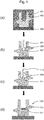
- Figure 1 shows selected schematic sections taken throughout a method of manufacture of a valve with hard facing.
- Figure 1(a) shows the step of forming the component body 101, here a valve body using an additive manufacturing process of laser melting/sintering.
- a powder bed 103 is placed on a supporting baseplate 105, and selected areas of the powder bed as defined by a 3D product model are melted using a laser to form a solid component body.
- the solid component body is surrounded by un-melted powder which is subsequently removed once the melting/sintering process is complete to leave the component body as shown in Figure 1(b) .
- the powder is typically vacuumed away, however where the internal features are complex, the component may be manipulated to encourage the powder to flow out. For very complex parts, ultrasonic wash stations may be used.
- the component body is here made entirely from grade 316 stainless steel.
- the component body 101 is formed to define a cavity 107.
- the component body 101 is formed to be a near-net shape component comprising sacrificial portions 109.
- the cavity in the component body is partially defined by these sacrificial portions of the component body, and partially defined by non-sacrificial portions.
- the shape of the cavity is selected so as to control deformation during the hot isostatic pressing step.
- the cavity 107 is part-filled with a powder 111 of a second material (here a material from the Tristelle alloy family) via an opening 113.
- the level of filling is selected as appropriate given the desired final design of the component.
- the incorporation of the second material into the component is for the purpose of producing a hard-facing on a valve, it is not necessary to fill the entire cavity. Rather, by part-filling the cavity, the process can achieve a more economical usage of raw materials.
- the entire component then undergoes a hot isostatic pressing cycle, during which the second material powder 111 densifies and bonds to the component body 101 at the cavity walls, thereby forming a consolidated component 120.
- the consolidated component is further processed (e.g. machined) to remove sacrificial portions 109 of the component body, along with excess second material.
- the final product, shown in Figure 1(d) is a consolidated component comprising a valve body portion 115 of a first material having an integrated hard facing 117 of a second material at the location of the original cavity.
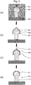
- Figure 2 shows selected schematic sections taken throughout a method of manufacture of a pipe with internal cladding.
- the method of manufacture is similar to that described above in relation to manufacture of a valve with hard facing.
- a component body 201 of a first material e.g. mild steel
- the component body 201 is formed to define an annular cavity 207 around the central shaft of the pipe.
- the cavity has an opening 213 through which a powder 211 of a second material (e.g. stainless steel) is inserted to fill the cavity.
- the component body is formed such that the cavity 207 is partially defined by sacrificial portions 209 of the component body (here the radially inner cavity wall), and partially defined by non-sacrificial portions (here the radially outer cavity wall).
- the component undergoes a hot isostatic pressing cycle to form the consolidated component 220 followed by removal of sacrificial portions of the component body.
- the final product is a consolidated component comprising a pipe body portion 215 of a first material having exposed integrated interior surface cladding 217 of a second material at the location of the original cavity.
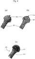
- Figures 3 and 4 show selected schematic sections taken throughout a method of manufacture of an artificial hip joint having a hard-wearing coating material covering a part of the joint.
- Figure 4 (a) and (b) are 3D rendered equivalents of a component as shown in Figure 3 (b) .
- Figure 4(c) is a 3D rendered equivalent of Fig. 3(d) .
- the method of manufacture is similar to that described above in relation to manufacture of a valve with hard facing.
- a component body 301 of a first material is fabricated using a method of additive manufacture from a powder bed 303 supported by a baseplate 305.
- the component body 301 is formed to define an approximately hemispherical cavity 307 surrounding the ball joint portion of the artificial hip joint.
- An opening 313 is provided at the centre of the hemispherical cavity, and the cavity is filled with powder 311 of a second material through said opening.
- the component body is formed such that the hemispherical cavity 307 is partially defined by a radially outer shell which is a sacrificial portion 309 of the component body, and partially defined by a non-sacrificial ball-joint portion of the component body.
- the component undergoes a hot isostatic pressing cycle to form the consolidated component 320 followed by removal of sacrificial portions of the component body.
- the final product is a consolidated component comprising a hip joint body portion 315 of a first material having an integrated surface covering 317 of a second material at the location of the original cavity.
Landscapes
- Engineering & Computer Science (AREA)
- Manufacturing & Machinery (AREA)
- Chemical & Material Sciences (AREA)
- Materials Engineering (AREA)
- Mechanical Engineering (AREA)
- Physics & Mathematics (AREA)
- Health & Medical Sciences (AREA)
- Optics & Photonics (AREA)
- Plasma & Fusion (AREA)
- Orthopedic Medicine & Surgery (AREA)
- Composite Materials (AREA)
- Biomedical Technology (AREA)
- Heart & Thoracic Surgery (AREA)
- Veterinary Medicine (AREA)
- General Health & Medical Sciences (AREA)
- Animal Behavior & Ethology (AREA)
- Life Sciences & Earth Sciences (AREA)
- Vascular Medicine (AREA)
- Public Health (AREA)
- Transplantation (AREA)
- Oral & Maxillofacial Surgery (AREA)
- Cardiology (AREA)
- Thermal Sciences (AREA)
- Ceramic Engineering (AREA)
- Powder Metallurgy (AREA)
Abstract
There is provided a method of manufacture of a component from multiple materials, and a consolidated component formed thereby. The method includes the steps of forming a component body comprising a first material, the component body defining a cavity, filling at least a portion of the cavity with a second material, and performing hot isostatic pressing of the component body and second material to form a consolidated component. The process offers a reduced-complexity, reduced-part-count method of manufacture for components formed of multiple materials.
Description
- The present disclosure relates to a method of manufacturing a component formed of multiple materials. More specifically, it relates to a method of manufacturing a component formed of multiple materials using hot isostatic pressing.
- Hot isostatic pressing (HIP) is a well-known manufacturing or processing technique in which high isostatic pressure is applied to a material, typically a powder within a canister, at an elevated temperature to provide isostatic compression. Typically, this process is performed in an inert atmosphere, e.g. in an argon gas atmosphere. This has applications in reducing the porosity and increasing density of metal and ceramic materials, or in forming a compact solid from a powder body in sintering processes.
- Hot isostatic pressing is typically used in the manufacture of a wide range of components. For the production of components formed of multiple materials, the manufacturing process will generally involve multiple machining and hot isostatic pressing stages. This can result in a complex manufacturing process. Furthermore, where a manufacturing process includes multiple hot isostatic pressing stages, e.g. where separate initial component parts undergo a first HIP cycle for densification and are subsequently bonded together using a second HIP cycle, this repeated exposure of component parts to high temperatures can cause undesirable degradation in the mechanical properties of the component parts due to grain coarsening resulting from multiple cycles at elevated temperatures.
- An example of a known process in which these problems typically occur includes the manufacture of valves having hard-facings, which typically require a minimum of two HIP cycles: an initial HIP cycle to form and densify the main body of the valve, and a second HIP 'bonding' cycle to bond the hard-facing component part to the main body of the valve. However, such problems may also be prevalent in many different technical fields where it is desired to produce components formed of multiple materials using a process of hot isostatic pressing.
- Accordingly, there is a desire to provide a method of manufacture of a component formed of multiple materials which reduces, preferably overcomes, the above mentioned problems.
- In a first aspect, there is provided a method of manufacturing a component from multiple materials including the steps of:
- forming a component body comprising a first material, the component body defining a cavity;
- filling at least a portion of the cavity with a second material; and
- performing hot isostatic pressing of the component body and second material to form a consolidated component.
- During the step of hot isostatic pressing, the second material located in the cavity defined by the component body undergoes densification and/or is consolidated into a solid mass whilst undergoing bonding to the component body, thus forming a consolidated component comprising the first material of the component body and the second material.
- In this way, the present process may allow for a reduction in lead time and supply chain complexity which is at least in part enabled by the reduction in the total number of HIP stages needed to form a consolidated component from multiple materials. The present process may require only a single HIP cycle to form a consolidated component.
- Furthermore, the present process may also allow for the total part count of the manufacturing process to be reduced relative to some known manufacturing processes. This is because in comparison to some known processes, where a first material component and a second material component may be joined together using HIP to form a consolidated component, in the present process, the second material component does not exist as a separate component before the HIP step. Rather, the second material portion of the component is added to the main component body from raw material.
- Optional features will now be set out. These are applicable singly or in any combination with any aspect.
- The terms "first material" and "second material" are generally used herein to indicate materials which differ from one another. That is, the first material and the second material may differ in class of material (e.g. metal/ceramic/polymer), or may both be the same class of material but having different chemical compositions (e.g. two metal alloys with different compositions) or different physical properties e.g. different densities, particle sizes etc. The precise materials of the component body and the second material are not particularly limited. Indeed, it is contemplated that the present method may be suitable for use with a wide range of material combinations, as will be readily understood by the skilled person.
- The second material may be a powder. A powder material may be advantageous as it may be easier to completely fill a cavity having complex geometry with a powder material.
- The method may comprise forming the component body using an additive manufacturing process. For example, the method may comprise forming the component body using any one of laser/electron beam melting/sintering; powder bed fusion; 3D printing; selective laser sintering/melting; a blown powder process; direct laser deposition; freeform manufacture; or additive layer manufacturing. The skilled person will be aware of a wide range additive manufacturing processes which would be suitable for use in the manufacturing process disclosed herein.
- Use of such an additive manufacturing process may enable the production of complex part geometry. For example, additive manufacture may allow more simple production of parts having re-entrant portions, or fine detail.
- Alternatively, the method may comprise forming the component body by machining. In particular, machining may be particularly advantageous for simple components, due to the typically lower manufacturing costs in comparison to additive manufacturing.
- The method may comprise forming the component body as a net or near-net shape component. As is generally understood, the term "net shape" herein refers to a component body that requires no post-HIP re-shaping or machining to satisfy its final design shape criteria. The term "near net shape" is a shape that requires only minimal machining or reshaping post-HIP to meet its final design shape criteria.
- The method may comprise forming the component body comprising one or more sacrificial portions which may partly define the cavity. The method may further comprise removing the one or more sacrificial portions after performing hot isostatic pressing of the component body and second material to form a consolidated component.
- Alternatively, the method may comprise forming the component body such that the cavity is entirely defined by non-sacrificial portions of the component body. Accordingly, the component body may be a net shape component.
- The geometry of the cavity may be selected so as to control the deformation which occurs during the HIP process. For example, where the cavity is partially defined by a sacrificial portion of the component body, the cavity geometry may be selected so that only deformation of the sacrificial portion of the component body occurs during HIP, or so that only a limited amount of deformation occurs to non-sacrificial portions of the component body. This may be done, for example, by controlling the wall thickness of the sacrificial material to encourage preferential deformation of the sacrificial material over deformation of non-sacrificial portions of the component body. In this way, unwanted deformation of the body of the consolidated component may be reduced or avoided.
- The method will generally comprise filling at least a portion of the cavity with the second material through at least one, and optionally multiple, external openings. However, alternative embodiments are also contemplated. For example, one alternative embodiment includes filling a half-formed cavity mid-way through the process of forming a component body by, for example, additive manufacturing. In such an embodiment, the component body defines a cavity filled with a second material where the cavity does not have any external openings. Here the term 'filling' includes both part filling, and totally filling the cavity. The total volume of second material inserted into the cavity may therefore be equal to or less than the total volume of the cavity to be filled. The precise amount of second material may be selected as appropriate for the intended design of the consolidated component.
- Whilst the above description makes reference to 'a cavity' it will clearly be understood that the process is not limited to a single cavity. The method may comprise forming the component body to define more than one cavity. For example, the method may comprise forming component body to define two, three, or four or more cavities. The number of cavities is not particularly limited and may be selected as appropriate given the desired features of the consolidated component. Where there are multiple cavities, the method may comprise at least part-filling all cavities with a second material before the step of hot isostatic pressing to form the consolidated component. It will be understood that multiple different second materials may be used to fill the respective multiple cavities before the hot isostatic pressing step. Furthermore, where the method includes forming a component body defining multiple cavities, such cavities may be of different shapes and sizes and may be filled to differing degrees, as appropriate.
- In a second aspect, there is provided a consolidated component formed by the method according to the first aspect.
- As discussed above, the present process requires only a single HIP cycle to achieve both densification of the component, and bonding of the first and second materials. In this case, the overall mechanical properties of the component may be improved, because it is not necessary for the component body to undergo multiple HIP cycles at elevated temperatures which may cause grain coarsening.
- It is contemplated that a wide range of components across a broad range of technical fields could be formed using the method of manufacture disclosed herein. Indeed, the present method may be suitable for any components where multiple materials are required, and when hot isostatic pressing is a generally preferred manufacturing process. Examples components include but are in no way limited to: valves, components having hard facings, cladded components, components having embedded electrically conductive material etc.
- Such components may find use in technical fields including but not limited to nuclear engineering, submarines, oil & gas engineering, marine engineering, aerospace engineering, automotive engineering, space exploration, and the medical field.
- Embodiments will now be described by way of example with reference to the accompanying drawings in which:
-
Figures 1(a)-(d) show selected schematic sections taken throughout a method of manufacture of a valve with hard facing; -
Figures 2(a)-(d) show selected schematic sections taken throughout a method of manufacture of a pipe with internal cladding; -
Figures 3(a)-(d) show selected schematic sections taken throughout a method of manufacture of an artificial hip joint having a hard-wearing coating material; and -
Figures 4(a)-(c) show 3D rendered versions of the articles shown inFigure 3 . -
Figure 1 shows selected schematic sections taken throughout a method of manufacture of a valve with hard facing. -
Figure 1(a) shows the step of forming thecomponent body 101, here a valve body using an additive manufacturing process of laser melting/sintering. In a manner well-known to those in the art, apowder bed 103 is placed on a supportingbaseplate 105, and selected areas of the powder bed as defined by a 3D product model are melted using a laser to form a solid component body. After the additive manufacture process is complete, the solid component body is surrounded by un-melted powder which is subsequently removed once the melting/sintering process is complete to leave the component body as shown inFigure 1(b) . The powder is typically vacuumed away, however where the internal features are complex, the component may be manipulated to encourage the powder to flow out. For very complex parts, ultrasonic wash stations may be used. The component body is here made entirely from grade 316 stainless steel. - The
component body 101 is formed to define acavity 107. Here, thecomponent body 101 is formed to be a near-net shape component comprisingsacrificial portions 109. In the present example, the cavity in the component body is partially defined by these sacrificial portions of the component body, and partially defined by non-sacrificial portions. The shape of the cavity is selected so as to control deformation during the hot isostatic pressing step. - In
Figure 1(c) , thecavity 107 is part-filled with apowder 111 of a second material (here a material from the Tristelle alloy family) via anopening 113. The level of filling is selected as appropriate given the desired final design of the component. Here, because the incorporation of the second material into the component is for the purpose of producing a hard-facing on a valve, it is not necessary to fill the entire cavity. Rather, by part-filling the cavity, the process can achieve a more economical usage of raw materials. - The entire component then undergoes a hot isostatic pressing cycle, during which the
second material powder 111 densifies and bonds to thecomponent body 101 at the cavity walls, thereby forming aconsolidated component 120. - Post-densification, the consolidated component is further processed (e.g. machined) to remove
sacrificial portions 109 of the component body, along with excess second material. The final product, shown inFigure 1(d) is a consolidated component comprising avalve body portion 115 of a first material having an integrated hard facing 117 of a second material at the location of the original cavity. -
Figure 2 shows selected schematic sections taken throughout a method of manufacture of a pipe with internal cladding. The method of manufacture is similar to that described above in relation to manufacture of a valve with hard facing. Initially, acomponent body 201 of a first material (e.g. mild steel) is fabricated using a method of additive manufacture from apowder bed 203 supported by abaseplate 205. Here, thecomponent body 201 is formed to define anannular cavity 207 around the central shaft of the pipe. The cavity has anopening 213 through which apowder 211 of a second material (e.g. stainless steel) is inserted to fill the cavity. The component body is formed such that thecavity 207 is partially defined bysacrificial portions 209 of the component body (here the radially inner cavity wall), and partially defined by non-sacrificial portions (here the radially outer cavity wall). - In the same manner as discussed in relation to the previous example, once the
cavity 207 has been filled withpowder 211 the component undergoes a hot isostatic pressing cycle to form theconsolidated component 220 followed by removal of sacrificial portions of the component body. The final product is a consolidated component comprising apipe body portion 215 of a first material having exposed integratedinterior surface cladding 217 of a second material at the location of the original cavity. -
Figures 3 and4 show selected schematic sections taken throughout a method of manufacture of an artificial hip joint having a hard-wearing coating material covering a part of the joint.Figure 4 (a) and (b) are 3D rendered equivalents of a component as shown inFigure 3 (b) .Figure 4(c) is a 3D rendered equivalent ofFig. 3(d) . The method of manufacture is similar to that described above in relation to manufacture of a valve with hard facing. Initially, acomponent body 301 of a first material is fabricated using a method of additive manufacture from apowder bed 303 supported by abaseplate 305. Here, thecomponent body 301 is formed to define an approximatelyhemispherical cavity 307 surrounding the ball joint portion of the artificial hip joint. Anopening 313 is provided at the centre of the hemispherical cavity, and the cavity is filled withpowder 311 of a second material through said opening. The component body is formed such that thehemispherical cavity 307 is partially defined by a radially outer shell which is asacrificial portion 309 of the component body, and partially defined by a non-sacrificial ball-joint portion of the component body. - In the same manner as discussed in relation to the previous example, the component undergoes a hot isostatic pressing cycle to form the
consolidated component 320 followed by removal of sacrificial portions of the component body. The final product is a consolidated component comprising a hipjoint body portion 315 of a first material having an integrated surface covering 317 of a second material at the location of the original cavity. - It will be understood that the disclosure is not limited to the embodiments above-described and various modifications and improvements can be made without departing from the concepts described herein. Except where mutually exclusive, any of the features may be employed separately or in combination with any other features and the disclosure extends to and includes all combinations and sub-combinations of one or more features described herein.
Claims (9)
- A method of manufacturing a component from multiple materials including the steps of:forming a component body comprising a first material, the component body defining a cavity;filling at least a portion of the cavity with a second material; andperforming hot isostatic pressing of the component body and second material to form a consolidated component.
- The method of manufacturing according to Claim 1 wherein the second material is a powder material.
- The method according to Claim 1 or Claim 2 comprising forming the component body using an additive manufacturing process.
- The method according to Claim 3 wherein the additive manufacturing process is one of laser/electron beam melting/sintering; powder bed fusion; 3D printing; selective laser sintering/melting; a blown powder process; direct laser deposition; freeform manufacture; or additive layer manufacturing.
- The method according to Claim 1 or Claim 2 comprising forming the component body by machining.
- The method according to any one of the preceding claims comprising forming the component body comprising one or more sacrificial portions which partly define the cavity.
- The method according to Claim 5 further comprising removing the sacrificial portion(s) of the component body after the step of performing hot isostatic pressing.
- The method according to any one of the preceding claims comprising forming the component body as a net or near-net shape component.
- A consolidated component formed by the method according to any one of Claims 1 to 8.
Applications Claiming Priority (1)
| Application Number | Priority Date | Filing Date | Title |
|---|---|---|---|
| GBGB1721769.6A GB201721769D0 (en) | 2017-12-22 | 2017-12-22 | A manufacturing method |
Publications (1)
| Publication Number | Publication Date |
|---|---|
| EP3501697A1 true EP3501697A1 (en) | 2019-06-26 |
Family
ID=61131740
Family Applications (1)
| Application Number | Title | Priority Date | Filing Date |
|---|---|---|---|
| EP18207850.1A Withdrawn EP3501697A1 (en) | 2017-12-22 | 2018-11-22 | A manufacturing method |
Country Status (3)
| Country | Link |
|---|---|
| US (1) | US20190193161A1 (en) |
| EP (1) | EP3501697A1 (en) |
| GB (1) | GB201721769D0 (en) |
Cited By (1)
| Publication number | Priority date | Publication date | Assignee | Title |
|---|---|---|---|---|
| EP3868494A1 (en) * | 2020-02-24 | 2021-08-25 | Rolls-Royce plc | Isostatic pressing canister |
Families Citing this family (1)
| Publication number | Priority date | Publication date | Assignee | Title |
|---|---|---|---|---|
| CN113664217B (en) * | 2021-07-08 | 2023-01-13 | 中国科学院金属研究所 | Preparation method of structural functional gradient material |
Citations (4)
| Publication number | Priority date | Publication date | Assignee | Title |
|---|---|---|---|---|
| US20070020134A1 (en) * | 2005-07-23 | 2007-01-25 | Rolls-Royce Plc | Method of making metal components |
| US20160243621A1 (en) * | 2013-10-17 | 2016-08-25 | The Exone Company | Three-Dimensional Printed Hot Isostatic Pressing Containers and Processes for Making Same |
| EP3064295A1 (en) * | 2015-03-05 | 2016-09-07 | General Electric Company | Process for producing an article |
| US20170021423A1 (en) * | 2014-04-02 | 2017-01-26 | Sandvik Intelectual Property Ab | Method for manufacturing a metallic component by pre-manufactured bodies |
-
2017
- 2017-12-22 GB GBGB1721769.6A patent/GB201721769D0/en not_active Ceased
-
2018
- 2018-11-22 EP EP18207850.1A patent/EP3501697A1/en not_active Withdrawn
- 2018-12-10 US US16/214,471 patent/US20190193161A1/en not_active Abandoned
Patent Citations (4)
| Publication number | Priority date | Publication date | Assignee | Title |
|---|---|---|---|---|
| US20070020134A1 (en) * | 2005-07-23 | 2007-01-25 | Rolls-Royce Plc | Method of making metal components |
| US20160243621A1 (en) * | 2013-10-17 | 2016-08-25 | The Exone Company | Three-Dimensional Printed Hot Isostatic Pressing Containers and Processes for Making Same |
| US20170021423A1 (en) * | 2014-04-02 | 2017-01-26 | Sandvik Intelectual Property Ab | Method for manufacturing a metallic component by pre-manufactured bodies |
| EP3064295A1 (en) * | 2015-03-05 | 2016-09-07 | General Electric Company | Process for producing an article |
Cited By (2)
| Publication number | Priority date | Publication date | Assignee | Title |
|---|---|---|---|---|
| EP3868494A1 (en) * | 2020-02-24 | 2021-08-25 | Rolls-Royce plc | Isostatic pressing canister |
| US11565313B2 (en) | 2020-02-24 | 2023-01-31 | Rolls-Royce Plc | Isostatic pressing canister |
Also Published As
| Publication number | Publication date |
|---|---|
| GB201721769D0 (en) | 2018-02-07 |
| US20190193161A1 (en) | 2019-06-27 |
Similar Documents
| Publication | Publication Date | Title |
|---|---|---|
| EP3064295B1 (en) | Process for producing a compressor blade | |
| CN110462168B (en) | Part and method for producing a part using hybrid additive manufacturing techniques | |
| CN109865838B (en) | Additive manufacturing technology and application thereof | |
| EP0958262B1 (en) | Method for infiltrating preformed components and component assemblies | |
| JP6619141B2 (en) | Method for manufacturing an object using a powder product | |
| CN101918609B (en) | Method for making parts with an insert made of a metal-matrix composite material | |
| EP2995398B1 (en) | Article manufacturing method from powders | |
| US20130039799A1 (en) | Method of Making Near-Net Shapes From Powdered Metals | |
| JP6644007B2 (en) | Method for the production of parts made from metal or metal matrix composites and the result from a process comprising additive manufacturing followed by forging of said parts | |
| EP2551040A1 (en) | Method of manufacturing a component by hot isostatic pressing | |
| US7261855B2 (en) | Method and system for manufacturing of complex shape parts from powder materials by hot isostatic pressing with controlled pressure inside the tooling and providing the shape of the part by multi-layer inserts | |
| CN101780544A (en) | Method for forming refractory metal parts by using laser | |
| US20200086555A1 (en) | Hybrid methods of additive manufacturing | |
| JP2007314879A (en) | Method of making metallic composite foam component and preform for metallic composite component | |
| EP1613566B1 (en) | Method for producing ceramic molds and the molds formed by the method | |
| AU2011244998A1 (en) | Method for the manufacture of a shaped body as well as green compact | |
| EP0466401B1 (en) | Gear | |
| US10864714B2 (en) | Method and device for additively producing components | |
| EP3527864B1 (en) | Methods of manufacturing a valve or an element used to form a valve | |
| CN113573828A (en) | Additive manufacturing technology and application thereof | |
| EP3501697A1 (en) | A manufacturing method | |
| WO2016030654A1 (en) | A mould for use in a hot isostatic press | |
| EP2340905B1 (en) | A method of manufacturing a component | |
| US6939508B2 (en) | Method of manufacturing net-shaped bimetallic parts | |
| EP2679323A1 (en) | A method of producing a metallic body provided with a metallic cladding |
Legal Events
| Date | Code | Title | Description |
|---|---|---|---|
| PUAI | Public reference made under article 153(3) epc to a published international application that has entered the european phase |
Free format text: ORIGINAL CODE: 0009012 |
|
| STAA | Information on the status of an ep patent application or granted ep patent |
Free format text: STATUS: THE APPLICATION HAS BEEN PUBLISHED |
|
| AK | Designated contracting states |
Kind code of ref document: A1 Designated state(s): AL AT BE BG CH CY CZ DE DK EE ES FI FR GB GR HR HU IE IS IT LI LT LU LV MC MK MT NL NO PL PT RO RS SE SI SK SM TR |
|
| AX | Request for extension of the european patent |
Extension state: BA ME |
|
| STAA | Information on the status of an ep patent application or granted ep patent |
Free format text: STATUS: THE APPLICATION IS DEEMED TO BE WITHDRAWN |
|
| 18D | Application deemed to be withdrawn |
Effective date: 20200103 |