EP3501696A1 - Splatter shield systems and methods for additive manufacturing - Google Patents
Splatter shield systems and methods for additive manufacturing Download PDFInfo
- Publication number
- EP3501696A1 EP3501696A1 EP18207473.2A EP18207473A EP3501696A1 EP 3501696 A1 EP3501696 A1 EP 3501696A1 EP 18207473 A EP18207473 A EP 18207473A EP 3501696 A1 EP3501696 A1 EP 3501696A1
- Authority
- EP
- European Patent Office
- Prior art keywords
- splatter
- shield
- build area
- shields
- splatter shield
- Prior art date
- Legal status (The legal status is an assumption and is not a legal conclusion. Google has not performed a legal analysis and makes no representation as to the accuracy of the status listed.)
- Withdrawn
Links
Images


Classifications
-
- B—PERFORMING OPERATIONS; TRANSPORTING
- B33—ADDITIVE MANUFACTURING TECHNOLOGY
- B33Y—ADDITIVE MANUFACTURING, i.e. MANUFACTURING OF THREE-DIMENSIONAL [3D] OBJECTS BY ADDITIVE DEPOSITION, ADDITIVE AGGLOMERATION OR ADDITIVE LAYERING, e.g. BY 3D PRINTING, STEREOLITHOGRAPHY OR SELECTIVE LASER SINTERING
- B33Y10/00—Processes of additive manufacturing
-
- B—PERFORMING OPERATIONS; TRANSPORTING
- B22—CASTING; POWDER METALLURGY
- B22F—WORKING METALLIC POWDER; MANUFACTURE OF ARTICLES FROM METALLIC POWDER; MAKING METALLIC POWDER; APPARATUS OR DEVICES SPECIALLY ADAPTED FOR METALLIC POWDER
- B22F10/00—Additive manufacturing of workpieces or articles from metallic powder
-
- B—PERFORMING OPERATIONS; TRANSPORTING
- B22—CASTING; POWDER METALLURGY
- B22F—WORKING METALLIC POWDER; MANUFACTURE OF ARTICLES FROM METALLIC POWDER; MAKING METALLIC POWDER; APPARATUS OR DEVICES SPECIALLY ADAPTED FOR METALLIC POWDER
- B22F12/00—Apparatus or devices specially adapted for additive manufacturing; Auxiliary means for additive manufacturing; Combinations of additive manufacturing apparatus or devices with other processing apparatus or devices
- B22F12/50—Means for feeding of material, e.g. heads
- B22F12/52—Hoppers
-
- B—PERFORMING OPERATIONS; TRANSPORTING
- B22—CASTING; POWDER METALLURGY
- B22F—WORKING METALLIC POWDER; MANUFACTURE OF ARTICLES FROM METALLIC POWDER; MAKING METALLIC POWDER; APPARATUS OR DEVICES SPECIALLY ADAPTED FOR METALLIC POWDER
- B22F12/00—Apparatus or devices specially adapted for additive manufacturing; Auxiliary means for additive manufacturing; Combinations of additive manufacturing apparatus or devices with other processing apparatus or devices
- B22F12/60—Planarisation devices; Compression devices
- B22F12/63—Rollers
-
- B—PERFORMING OPERATIONS; TRANSPORTING
- B22—CASTING; POWDER METALLURGY
- B22F—WORKING METALLIC POWDER; MANUFACTURE OF ARTICLES FROM METALLIC POWDER; MAKING METALLIC POWDER; APPARATUS OR DEVICES SPECIALLY ADAPTED FOR METALLIC POWDER
- B22F12/00—Apparatus or devices specially adapted for additive manufacturing; Auxiliary means for additive manufacturing; Combinations of additive manufacturing apparatus or devices with other processing apparatus or devices
- B22F12/60—Planarisation devices; Compression devices
- B22F12/67—Blades
-
- B—PERFORMING OPERATIONS; TRANSPORTING
- B22—CASTING; POWDER METALLURGY
- B22F—WORKING METALLIC POWDER; MANUFACTURE OF ARTICLES FROM METALLIC POWDER; MAKING METALLIC POWDER; APPARATUS OR DEVICES SPECIALLY ADAPTED FOR METALLIC POWDER
- B22F12/00—Apparatus or devices specially adapted for additive manufacturing; Auxiliary means for additive manufacturing; Combinations of additive manufacturing apparatus or devices with other processing apparatus or devices
- B22F12/70—Gas flow means
-
- B—PERFORMING OPERATIONS; TRANSPORTING
- B33—ADDITIVE MANUFACTURING TECHNOLOGY
- B33Y—ADDITIVE MANUFACTURING, i.e. MANUFACTURING OF THREE-DIMENSIONAL [3D] OBJECTS BY ADDITIVE DEPOSITION, ADDITIVE AGGLOMERATION OR ADDITIVE LAYERING, e.g. BY 3D PRINTING, STEREOLITHOGRAPHY OR SELECTIVE LASER SINTERING
- B33Y30/00—Apparatus for additive manufacturing; Details thereof or accessories therefor
-
- B—PERFORMING OPERATIONS; TRANSPORTING
- B33—ADDITIVE MANUFACTURING TECHNOLOGY
- B33Y—ADDITIVE MANUFACTURING, i.e. MANUFACTURING OF THREE-DIMENSIONAL [3D] OBJECTS BY ADDITIVE DEPOSITION, ADDITIVE AGGLOMERATION OR ADDITIVE LAYERING, e.g. BY 3D PRINTING, STEREOLITHOGRAPHY OR SELECTIVE LASER SINTERING
- B33Y40/00—Auxiliary operations or equipment, e.g. for material handling
-
- B—PERFORMING OPERATIONS; TRANSPORTING
- B33—ADDITIVE MANUFACTURING TECHNOLOGY
- B33Y—ADDITIVE MANUFACTURING, i.e. MANUFACTURING OF THREE-DIMENSIONAL [3D] OBJECTS BY ADDITIVE DEPOSITION, ADDITIVE AGGLOMERATION OR ADDITIVE LAYERING, e.g. BY 3D PRINTING, STEREOLITHOGRAPHY OR SELECTIVE LASER SINTERING
- B33Y50/00—Data acquisition or data processing for additive manufacturing
- B33Y50/02—Data acquisition or data processing for additive manufacturing for controlling or regulating additive manufacturing processes
-
- B—PERFORMING OPERATIONS; TRANSPORTING
- B22—CASTING; POWDER METALLURGY
- B22F—WORKING METALLIC POWDER; MANUFACTURE OF ARTICLES FROM METALLIC POWDER; MAKING METALLIC POWDER; APPARATUS OR DEVICES SPECIALLY ADAPTED FOR METALLIC POWDER
- B22F10/00—Additive manufacturing of workpieces or articles from metallic powder
- B22F10/20—Direct sintering or melting
- B22F10/28—Powder bed fusion, e.g. selective laser melting [SLM] or electron beam melting [EBM]
-
- B—PERFORMING OPERATIONS; TRANSPORTING
- B22—CASTING; POWDER METALLURGY
- B22F—WORKING METALLIC POWDER; MANUFACTURE OF ARTICLES FROM METALLIC POWDER; MAKING METALLIC POWDER; APPARATUS OR DEVICES SPECIALLY ADAPTED FOR METALLIC POWDER
- B22F10/00—Additive manufacturing of workpieces or articles from metallic powder
- B22F10/30—Process control
- B22F10/32—Process control of the atmosphere, e.g. composition or pressure in a building chamber
-
- B—PERFORMING OPERATIONS; TRANSPORTING
- B22—CASTING; POWDER METALLURGY
- B22F—WORKING METALLIC POWDER; MANUFACTURE OF ARTICLES FROM METALLIC POWDER; MAKING METALLIC POWDER; APPARATUS OR DEVICES SPECIALLY ADAPTED FOR METALLIC POWDER
- B22F10/00—Additive manufacturing of workpieces or articles from metallic powder
- B22F10/30—Process control
- B22F10/32—Process control of the atmosphere, e.g. composition or pressure in a building chamber
- B22F10/322—Process control of the atmosphere, e.g. composition or pressure in a building chamber of the gas flow, e.g. rate or direction
-
- B—PERFORMING OPERATIONS; TRANSPORTING
- B22—CASTING; POWDER METALLURGY
- B22F—WORKING METALLIC POWDER; MANUFACTURE OF ARTICLES FROM METALLIC POWDER; MAKING METALLIC POWDER; APPARATUS OR DEVICES SPECIALLY ADAPTED FOR METALLIC POWDER
- B22F10/00—Additive manufacturing of workpieces or articles from metallic powder
- B22F10/70—Recycling
- B22F10/73—Recycling of powder
-
- B—PERFORMING OPERATIONS; TRANSPORTING
- B22—CASTING; POWDER METALLURGY
- B22F—WORKING METALLIC POWDER; MANUFACTURE OF ARTICLES FROM METALLIC POWDER; MAKING METALLIC POWDER; APPARATUS OR DEVICES SPECIALLY ADAPTED FOR METALLIC POWDER
- B22F2201/00—Treatment under specific atmosphere
- B22F2201/10—Inert gases
-
- B—PERFORMING OPERATIONS; TRANSPORTING
- B23—MACHINE TOOLS; METAL-WORKING NOT OTHERWISE PROVIDED FOR
- B23K—SOLDERING OR UNSOLDERING; WELDING; CLADDING OR PLATING BY SOLDERING OR WELDING; CUTTING BY APPLYING HEAT LOCALLY, e.g. FLAME CUTTING; WORKING BY LASER BEAM
- B23K26/00—Working by laser beam, e.g. welding, cutting or boring
- B23K26/34—Laser welding for purposes other than joining
- B23K26/342—Build-up welding
-
- B—PERFORMING OPERATIONS; TRANSPORTING
- B29—WORKING OF PLASTICS; WORKING OF SUBSTANCES IN A PLASTIC STATE IN GENERAL
- B29C—SHAPING OR JOINING OF PLASTICS; SHAPING OF MATERIAL IN A PLASTIC STATE, NOT OTHERWISE PROVIDED FOR; AFTER-TREATMENT OF THE SHAPED PRODUCTS, e.g. REPAIRING
- B29C64/00—Additive manufacturing, i.e. manufacturing of three-dimensional [3D] objects by additive deposition, additive agglomeration or additive layering, e.g. by 3D printing, stereolithography or selective laser sintering
- B29C64/10—Processes of additive manufacturing
- B29C64/141—Processes of additive manufacturing using only solid materials
- B29C64/153—Processes of additive manufacturing using only solid materials using layers of powder being selectively joined, e.g. by selective laser sintering or melting
-
- B—PERFORMING OPERATIONS; TRANSPORTING
- B29—WORKING OF PLASTICS; WORKING OF SUBSTANCES IN A PLASTIC STATE IN GENERAL
- B29C—SHAPING OR JOINING OF PLASTICS; SHAPING OF MATERIAL IN A PLASTIC STATE, NOT OTHERWISE PROVIDED FOR; AFTER-TREATMENT OF THE SHAPED PRODUCTS, e.g. REPAIRING
- B29C64/00—Additive manufacturing, i.e. manufacturing of three-dimensional [3D] objects by additive deposition, additive agglomeration or additive layering, e.g. by 3D printing, stereolithography or selective laser sintering
- B29C64/30—Auxiliary operations or equipment
- B29C64/35—Cleaning
-
- Y—GENERAL TAGGING OF NEW TECHNOLOGICAL DEVELOPMENTS; GENERAL TAGGING OF CROSS-SECTIONAL TECHNOLOGIES SPANNING OVER SEVERAL SECTIONS OF THE IPC; TECHNICAL SUBJECTS COVERED BY FORMER USPC CROSS-REFERENCE ART COLLECTIONS [XRACs] AND DIGESTS
- Y02—TECHNOLOGIES OR APPLICATIONS FOR MITIGATION OR ADAPTATION AGAINST CLIMATE CHANGE
- Y02P—CLIMATE CHANGE MITIGATION TECHNOLOGIES IN THE PRODUCTION OR PROCESSING OF GOODS
- Y02P10/00—Technologies related to metal processing
- Y02P10/25—Process efficiency
Definitions
- the present disclosure relates to additive manufacturing systems and methods.
- LPBF Laser Powder Bed Fusion
- a splatter shield system for an additive manufacturing machine includes one or more splatter shields configured to cover at least a portion of a build area during energy application such that the at least one splatter shield is positioned between an energy source of an additive manufacturing machine and the build area during energy application.
- the one or more splatter shields are transparent to an energy source (e.g., a laser) of the additive manufacturing system such that energy application occurs through the splatter shield.
- the one or more splatter shields can include a plate shape.
- the one or more splatter shields can be connected to and movable with a recoater system.
- the one or more splatter shields can include two splatter shields, one on each side of the recoater system.
- the recoater system can include at least one of a hopper, a roller recoater, or a knife recoater.
- the one or more splatter shields can be made of at least one of sapphire, quartz, or transparent polycrystalline ceramic.
- the energy source can be a laser. Any other suitable material suitably transparent for any other suitable energy application (e.g., electron beam) is contemplated herein.
- the splatter shield can be placed proximate the build area to form a gas flow channel for an inert gas to uniformly flow over the build area between the splatter shield and the build area.
- the splatter shield can be separated by less than an inch.
- the system can include a controller configured to control movement of the recoater system, wherein the controller is configured to place the one or more splatter shields over the build area during energy application.
- the system can include a splatter shield cleaning system configured to clean the one or more splatter shields.
- the splatter shield cleaning system can be configured to clean at least part of the one or more splatter shields during a recoating process.
- the splatter shield cleaning system can include a scraper configured to scrape an underside of the splatter shield as the shield moves over the scraper during the recoating process.
- a method can include placing a splatter shield over a build area of an additive manufacturing machine between an energy source and the build area during energy application.
- the splatter shield is transparent to the energy source and is positioned to prevent splatter from energy application.
- the method can include providing uniformly flowing inert gas between the splatter shield and the build area.
- the method can include cleaning the splatter shield during recoating of the build area.
- the method can include controlling a gap size between build area and the splatter shield.
- the gap size is controlled to minimize overall inert gas flow, and/or to direct inert gas flow at an interface of a laser beam and powder bed, and/or to flush out particles and/or condensate towards exhaust vents.
- FIG. 1 an illustrative view of an embodiment of a system in accordance with the disclosure is shown in Fig. 1 and is designated generally by reference character 100.
- FIGs. 2-4 Other embodiments and/or aspects of this disclosure are shown in Figs. 2-4 .
- the systems and methods described herein can be used to enhance environment control and build quality in an additive manufacturing system, for example, or for any other purpose.
- a splatter shield system 100 for an additive manufacturing machine includes one or more splatter shields 101 configured to cover at least a portion of a build area 103 (e.g., a powder bed) during energy application (e.g., as shown in Fig. 1 ) such that the at least one splatter shield 101 is positioned between an energy source 105 of an additive manufacturing machine and the build area 103 during energy application.
- the one or more splatter shields 101 are transparent to an energy source (e.g., a laser) of the additive manufacturing system such that energy application occurs through the splatter shield 101.
- the one or more splatter shields 101 can include a plate shape or any other suitable shape.
- the one or more splatter shields 101 can be sized to cover the entire build area 103 or any suitable portion thereof.
- the one or more splatter shields 101 can be connected to and movable with a recoater system 107 of the additive manufacturing machine.
- the one or more splatter shields 101 can include two splatter shields 101 as shown, one on each side of the recoater system 107.
- the recoater system 107 can include at least one of a hopper 109, a roller recoater (not shown), or one or more knife recoaters 111 (e.g., one on each side of the hopper 109 as shown).
- the one or more splatter shields 101 can be made of at least one of sapphire, quartz, or transparent polycrystalline ceramic (e.g., aluminum oxynitride).
- the energy source 105 can be a laser 113. Any other suitable material (e.g., a glass or other ceramic) suitably transparent for any other suitable energy application (e.g., electron beam) is contemplated herein.
- the splatter shield 101 can be placed proximate the build area 103 to form a gas flow channel 213 for an inert gas 215 (e.g., argon from a gas source 217) to uniformly flow over the build area 103 between the splatter shield 101 and the build area 103.
- an inert gas 215 e.g., argon from a gas source 217
- the splatter shield 101 can be separated by less than an inch from the build area 103. Any other suitable distance is contemplated herein (a few millimeters from the powder bed).
- Gas flow can be considered when selecting the distance from the build area 103 powder bed that the shields 101 are positioned.
- gas can be pumped through the flow channel 213, and can be laminar because of the relatively small volume.
- the gas flow can act like an air knife and clean the splatter shield 101 while keeping the build environment inert and pulling condensate or ejecta out of the build area 103
- the system 100 can include a controller 119 configured to control movement of the recoater system 107.
- the controller 119 can also be configured to place the one or more splatter shields 101 over the build area 103 during energy application (e.g., as shown in Figs. 1 and 4 ).
- the controller 119 can include any suitable hardware and/or software as appreciated by those having ordinary skill in the art and can be configured to execute any suitable method and/or portion thereof in accordance with this disclosure.
- the system 100 can include a splatter shield cleaning system 121 that is configured to clean the one or more splatter shields 101.
- the splatter shield cleaning system 121 can be configured to clean at least part of the one or more splatter shields 101 during a recoating process (e.g., as shown in Fig. 3 ).
- the splatter shield cleaning system 121 can include a scraper 123 (e.g., one or more brushes, blades, or other suitable device) configured to scrape an underside of the splatter shield 101 as the shield 101 moves over the scraper 123 during the recoating process (e.g., as shown in Fig. 3 ).
- one shield 101 can be used and the recoater can cycle back and forth each time and come to rest on the same side each time.
- two shields 101 can allow the other shield 101 to be cleaned while the other is in use.
- a method can include placing a splatter shield 101 over a build area 103 of an additive manufacturing machine between an energy source 105 and the build area 103 during energy application.
- the splatter shield 101 is transparent to the energy source 105 and is positioned to prevent splatter from energy application.
- the method can include providing uniformly flowing inert gas between the splatter shield and the build area.
- the method can include cleaning the splatter shield during recoating of the build area.
- the method can include activating the energy source 105 when the shield 101 is positioned over the build area 103.
- the method can include controlling a gap size between build area 103 and the splatter shield 101.
- the gap size is controlled to minimize overall inert gas flow, and/or to direct inert gas flow at an interface of a laser beam and powder bed, and/or to flush out particles and/or condensate towards exhaust vents.
- Embodiments utilize transparent splatter shields 101 in close proximity to a powder bed surface to facilitate a continuously sealed environment, providing the benefits of uniform gas flow coverage and preventing ejected particles from getting redeposited.
- Using two shields 101 can facilitate dual powder recoating in both directions for time efficiency.
- the gap (flow channel 213) between the shield 101 and the powder bed can be optimized for allowing adequate, uniform, shield gas flow across the build area 103.
- the volume under the shield 101 can be controlled by utilizing vacuum partial pressure.
- the working surface of the transparent shields 101 will get progressively contaminated.
- automatic shield replacement stations can be utilized to remove the used transparent shields 101 and install clean shields 101.
- the unused shields 101 can go through a cleaning process (e.g., using cleaning system 121 or any other suitable system or process).
- the shield 101 can provide a sealed environment for the powder bed below it but not impede the energy source (e.g., laser) that will be passing through it.
- one or more shields 101 can be fixed to the left and right sides of an existing recoater of a laser powder bed fusion device.
- a recoater spreads a thin layer of powder across the top of previously selectively-fused layers, building the object up additively.
- the recoater 107 can spread powder from left to right of the bed shown Figure 1 , and then the left ceramic plate would be covering the build area (novel).
- the energy source can then fuse the deposited powder to a substrate through the shield 101.
- the recoater would spread the next layer from right to left, and then the right plate would cover the build area. This process can be repeated until the part is complete.
- Using the one or more shields 101 can confine the redeposited particles to a close proximity to melt pool, for example, which minimizes the spread of the redepositied particles on the top of powder bed surface. Some of the ejected particles and/or condensate may attach to the one or more shields 101 and can be removed by a cleaning system as disclosed herein.
- Embodiments provide benefits such as creating a "sealed" build environment and catching ejected particles, for example.
- the sealed build environment minimizes the adverse effect of non-uniform flow of shield gas.
- Catching ejected particles from the melt pool (as well as melt pool condensate) and limiting the area of spread of particles (e.g., to the melt pool) can prevent the formation of harmful material contamination.
- This can improve microstructure/properties of the final part, e.g., high temperature ductility and notch sensitivity at elevated temperatures, and provide the opportunity for utilizing additively build aerospace quality alloys for demanding applications.
- a controlled gap between the powder bed and the one or more shields 101 can be used to minimize the overall inert gas flow, to direct the inert gas flow at the interface of laser beam and powder bed, and to effectively flush out the condensate towards exhaust vents.
- a sieved recycled powder will have fewer ejected particles/contaminants allowing for a greater number of powder reuses that will minimize the overall cost.
- aspects of the present disclosure may be embodied as a system, method or computer program product. Accordingly, aspects of the present invention may take the form of an entirely hardware embodiment, an entirely software embodiment (including firmware, resident software, micro-code, etc.) or an embodiment combining software and hardware aspects that may all generally be referred to herein as a "circuit,” “module” or “system.” Furthermore, aspects of the present invention may take the form of a computer program product embodied in one or more computer readable medium(s) having computer readable program code embodied thereon.
- the computer readable medium may be a computer readable signal medium or a computer readable storage medium.
- a computer readable storage medium may be, for example, but not limited to, an electronic, magnetic, optical, electromagnetic, infrared, or semiconductor system, apparatus, or device, or any suitable combination of the foregoing.
- a computer readable storage medium may be any tangible medium that can contain, or store a program for use by or in connection with an instruction execution system, apparatus, or device.
- a computer readable signal medium may include a propagated data signal with computer readable program code embodied therein, for example, in baseband or as part of a carrier wave. Such a propagated signal may take any of a variety of forms, including, but not limited to, electro-magnetic, optical, or any suitable combination thereof.
- a computer readable signal medium may be any computer readable medium that is not a computer readable storage medium and that can communicate, propagate, or transport a program for use by or in connection with an instruction execution system, apparatus, or device.
- Program code embodied on a computer readable medium may be transmitted using any appropriate medium, including but not limited to wireless, wireline, optical fiber cable, RF, etc., or any suitable combination of the foregoing.
- Computer program code for carrying out operations for aspects of the present invention may be written in any combination of one or more programming languages, including an object oriented programming language such as Java, Smalltalk, C++ or the like and conventional procedural programming languages, such as the "C" programming language or similar programming languages.
- the program code may execute entirely on the user's computer, partly on the user's computer, as a stand-alone software package, partly on the user's computer and partly on a remote computer or entirely on the remote computer or server.
- the remote computer may be connected to the user's computer through any type of network, including a local area network (LAN) or a wide area network (WAN), or the connection may be made to an external computer (for example, through the Internet using an Internet Service Provider).
- LAN local area network
- WAN wide area network
- Internet Service Provider for example, AT&T, MCI, Sprint, EarthLink, MSN, GTE, etc.
- These computer program instructions may also be stored in a computer readable medium that can direct a computer, other programmable data processing apparatus, or other devices to function in a particular manner, such that the instructions stored in the computer readable medium produce an article of manufacture including instructions which implement the function/act specified in the flowchart and/or block diagram block or blocks.
- the computer program instructions may also be loaded onto a computer, other programmable data processing apparatus, or other devices to cause a series of operational steps to be performed on the computer, other programmable apparatus or other devices to produce a computer implemented process such that the instructions which execute on the computer or other programmable apparatus provide processes for implementing the functions/acts specified herein.
Landscapes
- Engineering & Computer Science (AREA)
- Chemical & Material Sciences (AREA)
- Manufacturing & Machinery (AREA)
- Materials Engineering (AREA)
- Mechanical Engineering (AREA)
- Powder Metallurgy (AREA)
Abstract
Description
- The present disclosure relates to additive manufacturing systems and methods.
- During Laser Powder Bed Fusion (LPBF) a shield gas, such as Argon, is utilized to prevent material from oxidation. However, "dead zones" exist where material gets partially oxidized, resulting in inferior mechanical properties, because of non-uniform gas coverage.
- Also, during manufacturing, an ample amount of metal particles eject at the laser weld pool, become airborne, and get deposited back on top of powder bed along with product of metal evaporation (aka condensate). Chemical composition of the ejected particles and condensate exhibits much higher level of impurities than in a virgin powder.
- As a result of powder recoating motion, contaminated powder gets spread across the entire build area and fused into parts. The level of contamination increases with powder reuse/recycling.
- Such conventional methods and systems have generally been considered satisfactory for their intended purpose. However, there is still a need in the art for improved additive manufacturing systems and methods. The present disclosure provides a solution for this need.
- A splatter shield system for an additive manufacturing machine includes one or more splatter shields configured to cover at least a portion of a build area during energy application such that the at least one splatter shield is positioned between an energy source of an additive manufacturing machine and the build area during energy application. The one or more splatter shields are transparent to an energy source (e.g., a laser) of the additive manufacturing system such that energy application occurs through the splatter shield.
- The one or more splatter shields can include a plate shape. The one or more splatter shields can be connected to and movable with a recoater system.
- In certain embodiments, the one or more splatter shields can include two splatter shields, one on each side of the recoater system. For example, the recoater system can include at least one of a hopper, a roller recoater, or a knife recoater.
- The one or more splatter shields can be made of at least one of sapphire, quartz, or transparent polycrystalline ceramic. In certain embodiments, the energy source can be a laser. Any other suitable material suitably transparent for any other suitable energy application (e.g., electron beam) is contemplated herein.
- The splatter shield can be placed proximate the build area to form a gas flow channel for an inert gas to uniformly flow over the build area between the splatter shield and the build area. For example, the splatter shield can be separated by less than an inch. The system can include a controller configured to control movement of the recoater system, wherein the controller is configured to place the one or more splatter shields over the build area during energy application.
- The system can include a splatter shield cleaning system configured to clean the one or more splatter shields. The splatter shield cleaning system can be configured to clean at least part of the one or more splatter shields during a recoating process. The splatter shield cleaning system can include a scraper configured to scrape an underside of the splatter shield as the shield moves over the scraper during the recoating process.
- In accordance with at least one aspect of this disclosure, a method can include placing a splatter shield over a build area of an additive manufacturing machine between an energy source and the build area during energy application. The splatter shield is transparent to the energy source and is positioned to prevent splatter from energy application.
- The method can include providing uniformly flowing inert gas between the splatter shield and the build area. The method can include cleaning the splatter shield during recoating of the build area.
- The method can include controlling a gap size between build area and the splatter shield. The gap size is controlled to minimize overall inert gas flow, and/or to direct inert gas flow at an interface of a laser beam and powder bed, and/or to flush out particles and/or condensate towards exhaust vents.
- These and other features of the systems and methods of the subject disclosure will become more readily apparent to those skilled in the art from the following detailed description taken in conjunction with the drawings.
- So that those skilled in the art to which the subject disclosure appertains will readily understand how to make and use the devices and methods of the subject disclosure without undue experimentation, embodiments thereof will be described in detail herein below with reference to certain figures, wherein:
-
Fig. 1 is a perspective view of an embodiment of a system in accordance with this disclosure, showing the system in a first position and energy being applied to a build area; -
Fig. 2 is a schematic side view of the embodiment ofFig. 1 , showing a gas flowing between the shield and the build area. -
Fig. 3 is a perspective view and a zoomed view thereof of the embodiment ofFig. 1 in a recoating process, moving from left to right to recoat the build area; and -
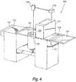
Fig. 4 is a perspective view of an embodiment of a system in accordance with this disclosure, showing the system in a second position and energy being applied to a build area. - Reference will now be made to the drawings wherein like reference numerals identify similar structural features or aspects of the subject disclosure. For purposes of explanation and illustration, and not limitation, an illustrative view of an embodiment of a system in accordance with the disclosure is shown in
Fig. 1 and is designated generally byreference character 100. Other embodiments and/or aspects of this disclosure are shown inFigs. 2-4 . The systems and methods described herein can be used to enhance environment control and build quality in an additive manufacturing system, for example, or for any other purpose. - Referring to
Fig. 1 , asplatter shield system 100 for an additive manufacturing machine includes one ormore splatter shields 101 configured to cover at least a portion of a build area 103 (e.g., a powder bed) during energy application (e.g., as shown inFig. 1 ) such that the at least onesplatter shield 101 is positioned between anenergy source 105 of an additive manufacturing machine and thebuild area 103 during energy application. The one ormore splatter shields 101 are transparent to an energy source (e.g., a laser) of the additive manufacturing system such that energy application occurs through thesplatter shield 101. - The one or more
splatter shields 101 can include a plate shape or any other suitable shape. The one ormore splatter shields 101 can be sized to cover theentire build area 103 or any suitable portion thereof. The one ormore splatter shields 101 can be connected to and movable with arecoater system 107 of the additive manufacturing machine. - In certain embodiments, the one or
more splatter shields 101 can include twosplatter shields 101 as shown, one on each side of therecoater system 107. For example, therecoater system 107 can include at least one of ahopper 109, a roller recoater (not shown), or one or more knife recoaters 111 (e.g., one on each side of thehopper 109 as shown). - The one or more
splatter shields 101 can be made of at least one of sapphire, quartz, or transparent polycrystalline ceramic (e.g., aluminum oxynitride). In certain embodiments, theenergy source 105 can be a laser 113. Any other suitable material (e.g., a glass or other ceramic) suitably transparent for any other suitable energy application (e.g., electron beam) is contemplated herein. - Referring additionally to
Fig. 2 , thesplatter shield 101 can be placed proximate thebuild area 103 to form agas flow channel 213 for an inert gas 215 (e.g., argon from a gas source 217) to uniformly flow over thebuild area 103 between thesplatter shield 101 and thebuild area 103. For example, thesplatter shield 101 can be separated by less than an inch from thebuild area 103. Any other suitable distance is contemplated herein (a few millimeters from the powder bed). - Gas flow can be considered when selecting the distance from the
build area 103 powder bed that theshields 101 are positioned. In accordance with certain embodiments, gas can be pumped through theflow channel 213, and can be laminar because of the relatively small volume. In certain embodiments, the gas flow can act like an air knife and clean thesplatter shield 101 while keeping the build environment inert and pulling condensate or ejecta out of thebuild area 103 - Referring additionally to
Figs. 3 and4 , thesystem 100 can include acontroller 119 configured to control movement of therecoater system 107. Thecontroller 119 can also be configured to place the one or more splatter shields 101 over thebuild area 103 during energy application (e.g., as shown inFigs. 1 and4 ). Thecontroller 119 can include any suitable hardware and/or software as appreciated by those having ordinary skill in the art and can be configured to execute any suitable method and/or portion thereof in accordance with this disclosure. - In certain embodiments, the
system 100 can include a splattershield cleaning system 121 that is configured to clean the one or more splatter shields 101. The splattershield cleaning system 121 can be configured to clean at least part of the one or more splatter shields 101 during a recoating process (e.g., as shown inFig. 3 ). The splattershield cleaning system 121 can include a scraper 123 (e.g., one or more brushes, blades, or other suitable device) configured to scrape an underside of thesplatter shield 101 as theshield 101 moves over thescraper 123 during the recoating process (e.g., as shown inFig. 3 ). - While embodiments show two
shields 101, oneshield 101 can be used and the recoater can cycle back and forth each time and come to rest on the same side each time. As is appreciated by those having ordinary skill in the art in view of this disclosure, twoshields 101 can allow theother shield 101 to be cleaned while the other is in use. - In accordance with at least one aspect of this disclosure, a method can include placing a
splatter shield 101 over abuild area 103 of an additive manufacturing machine between anenergy source 105 and thebuild area 103 during energy application. Thesplatter shield 101 is transparent to theenergy source 105 and is positioned to prevent splatter from energy application. - The method can include providing uniformly flowing inert gas between the splatter shield and the build area. The method can include cleaning the splatter shield during recoating of the build area. The method can include activating the
energy source 105 when theshield 101 is positioned over thebuild area 103. - The method can include controlling a gap size between
build area 103 and thesplatter shield 101. The gap size is controlled to minimize overall inert gas flow, and/or to direct inert gas flow at an interface of a laser beam and powder bed, and/or to flush out particles and/or condensate towards exhaust vents. - Embodiments utilize transparent splatter shields 101 in close proximity to a powder bed surface to facilitate a continuously sealed environment, providing the benefits of uniform gas flow coverage and preventing ejected particles from getting redeposited. Using two
shields 101 can facilitate dual powder recoating in both directions for time efficiency. The gap (flow channel 213) between theshield 101 and the powder bed can be optimized for allowing adequate, uniform, shield gas flow across thebuild area 103. In certain embodiments, the volume under theshield 101 can be controlled by utilizing vacuum partial pressure. - In certain cases, the working surface of the
transparent shields 101 will get progressively contaminated. In certain embodiments, automatic shield replacement stations can be utilized to remove the usedtransparent shields 101 and installclean shields 101. Alternatively, since only oneshield 101 is used per layer (e.g., either left or right as shown), theunused shields 101 can go through a cleaning process (e.g., usingcleaning system 121 or any other suitable system or process). Theshield 101 can provide a sealed environment for the powder bed below it but not impede the energy source (e.g., laser) that will be passing through it. - In certain embodiments, one or
more shields 101 can be fixed to the left and right sides of an existing recoater of a laser powder bed fusion device. As appreciated by those having ordinary skill in the art, a recoater spreads a thin layer of powder across the top of previously selectively-fused layers, building the object up additively. - As shown in
Fig. 3 , therecoater 107 can spread powder from left to right of the bed shownFigure 1 , and then the left ceramic plate would be covering the build area (novel). The energy source can then fuse the deposited powder to a substrate through theshield 101. When the layer is complete, the recoater would spread the next layer from right to left, and then the right plate would cover the build area. This process can be repeated until the part is complete. - Using the one or
more shields 101 can confine the redeposited particles to a close proximity to melt pool, for example, which minimizes the spread of the redepositied particles on the top of powder bed surface. Some of the ejected particles and/or condensate may attach to the one ormore shields 101 and can be removed by a cleaning system as disclosed herein. - Embodiments provide benefits such as creating a "sealed" build environment and catching ejected particles, for example. The sealed build environment minimizes the adverse effect of non-uniform flow of shield gas. Catching ejected particles from the melt pool (as well as melt pool condensate) and limiting the area of spread of particles (e.g., to the melt pool) can prevent the formation of harmful material contamination. This can improve microstructure/properties of the final part, e.g., high temperature ductility and notch sensitivity at elevated temperatures, and provide the opportunity for utilizing additively build aerospace quality alloys for demanding applications.
- Moreover, a controlled gap between the powder bed and the one or
more shields 101 can be used to minimize the overall inert gas flow, to direct the inert gas flow at the interface of laser beam and powder bed, and to effectively flush out the condensate towards exhaust vents. As a result, a sieved recycled powder will have fewer ejected particles/contaminants allowing for a greater number of powder reuses that will minimize the overall cost. - As will be appreciated by those skilled in the art, aspects of the present disclosure may be embodied as a system, method or computer program product. Accordingly, aspects of the present invention may take the form of an entirely hardware embodiment, an entirely software embodiment (including firmware, resident software, micro-code, etc.) or an embodiment combining software and hardware aspects that may all generally be referred to herein as a "circuit," "module" or "system." Furthermore, aspects of the present invention may take the form of a computer program product embodied in one or more computer readable medium(s) having computer readable program code embodied thereon.
- Any combination of one or more computer readable medium(s) may be utilized. The computer readable medium may be a computer readable signal medium or a computer readable storage medium. A computer readable storage medium may be, for example, but not limited to, an electronic, magnetic, optical, electromagnetic, infrared, or semiconductor system, apparatus, or device, or any suitable combination of the foregoing. More specific examples (a non-exhaustive list) of the computer readable storage medium would include the following: an electrical connection having one or more wires, a portable computer diskette, a hard disk, a random access memory (RAM), a read-only memory (ROM), an erasable programmable read-only memory (EPROM or Flash memory), an optical fiber, a portable compact disc read-only memory (CD-ROM), an optical storage device, a magnetic storage device, or any suitable combination of the foregoing. In the context of this document, a computer readable storage medium may be any tangible medium that can contain, or store a program for use by or in connection with an instruction execution system, apparatus, or device.
- A computer readable signal medium may include a propagated data signal with computer readable program code embodied therein, for example, in baseband or as part of a carrier wave. Such a propagated signal may take any of a variety of forms, including, but not limited to, electro-magnetic, optical, or any suitable combination thereof. A computer readable signal medium may be any computer readable medium that is not a computer readable storage medium and that can communicate, propagate, or transport a program for use by or in connection with an instruction execution system, apparatus, or device.
- Program code embodied on a computer readable medium may be transmitted using any appropriate medium, including but not limited to wireless, wireline, optical fiber cable, RF, etc., or any suitable combination of the foregoing.
- Computer program code for carrying out operations for aspects of the present invention may be written in any combination of one or more programming languages, including an object oriented programming language such as Java, Smalltalk, C++ or the like and conventional procedural programming languages, such as the "C" programming language or similar programming languages. The program code may execute entirely on the user's computer, partly on the user's computer, as a stand-alone software package, partly on the user's computer and partly on a remote computer or entirely on the remote computer or server. In the latter scenario, the remote computer may be connected to the user's computer through any type of network, including a local area network (LAN) or a wide area network (WAN), or the connection may be made to an external computer (for example, through the Internet using an Internet Service Provider).
- Aspects of the present invention may be described above with reference to flowchart illustrations and/or block diagrams of methods, apparatus (systems) and computer program products according to embodiments of the invention. It will be understood that any method and/or portion thereof can be implemented by computer program instructions. These computer program instructions may be provided to a processor of a general purpose computer, special purpose computer, or other programmable data processing apparatus to produce a machine, such that the instructions, which execute via the processor of the computer or other programmable data processing apparatus, create means for implementing the functions/acts specified in any flowchart and/or block diagram block or blocks.
- These computer program instructions may also be stored in a computer readable medium that can direct a computer, other programmable data processing apparatus, or other devices to function in a particular manner, such that the instructions stored in the computer readable medium produce an article of manufacture including instructions which implement the function/act specified in the flowchart and/or block diagram block or blocks.
- The computer program instructions may also be loaded onto a computer, other programmable data processing apparatus, or other devices to cause a series of operational steps to be performed on the computer, other programmable apparatus or other devices to produce a computer implemented process such that the instructions which execute on the computer or other programmable apparatus provide processes for implementing the functions/acts specified herein.
- Any suitable combination(s) of any disclosed embodiments and/or any suitable portion(s) thereof is contemplated therein as appreciated by those having ordinary skill in the art.
- The embodiments of the present disclosure, as described above and shown in the drawings, provide for improvement in the art to which they pertain. While the subject disclosure includes reference to certain embodiments, those skilled in the art will readily appreciate that changes and/or modifications may be made thereto without departing from the scope of the subject disclosure.
Claims (15)
- A splatter shield system (100) for an additive manufacturing machine, comprising:one or more splatter shields (101) configured to cover at least a portion of a build area (103) during energy application such that the at least one splatter shield (101) is positioned between an energy source (105) of an additive manufacturing machine and the build area (103) during energy application, wherein the one or more splatter shields (101) are transparent to the energy source (105) of the additive manufacturing system such that energy application occurs through the splatter shield (101).
- The system of claim 1, wherein the one or more splatter shields (101) includes a plate shape.
- The system of claims 1 or 2, wherein the one or more splatter shields (101) are connected to and movable with a recoater system (107).
- The system of claim 3, wherein the one or more splatter shields (101) includes two splatter shields, one on each side of the recoater system (107), or
wherein the recoater system (107) includes at least one of a hopper, a roller recoater, or a knife recoater. - The system of any preceding claim, wherein the one or more splatter shields (101) are made of at least one of sapphire, quartz, or transparent polycrystalline ceramic.
- The system of any preceding claim, wherein the splatter shield (101) is placed proximate the build area (103) to form a gas flow channel for an inert gas to uniformly flow over the build area (103) between the splatter shield (101) and the build area (103).
- The system of claim 5, wherein the energy source (105) is a laser.
- The system of any preceding claim, wherein the system includes a controller (119) configured to control movement of the recoater system (107), wherein the controller (119) is configured to place the one or more splatter shields (101) over the build area (103) during energy application.
- The system of any preceding claim, wherein the system includes a splatter shield cleaning system (121) configured to clean the one or more splatter shields (101).
- The system of claim 9, wherein the splatter shield cleaning system (121) is configured to clean at least part of the one or more splatter shields (101) during a recoating process, and preferably
wherein the splatter shield cleaning system (121) includes a scraper (123) configured to scrape an underside of the splatter shield (101) as the shield moves over the scraper (123) during the recoating process. - A method, comprising:placing a splatter shield (101) over a build area (103) of an additive manufacturing machine between an energy source (105) and the build area (103) during energy application, wherein the splatter shield (101) is transparent to the energy source (105) and is positioned to prevent splatter from energy application.
- The method, of claim 11, further comprising providing uniformly flowing inert gas between the splatter shield (101) and the build area (103).
- The method of claims 11 or 12, further comprising cleaning the splatter shield during recoating of the build area (103).
- The method of any of claims 11-13, further comprising controlling a gap size between build area (103) and the splatter shield (101).
- The method of claim 14, wherein the gap size is controlled to minimize overall inert gas flow, and/or to direct inert gas flow at an interface of a laser beam and powder bed, and/or to flush out particles and/or condensate towards exhaust vents.
Applications Claiming Priority (1)
| Application Number | Priority Date | Filing Date | Title |
|---|---|---|---|
| US15/820,236 US11027336B2 (en) | 2017-11-21 | 2017-11-21 | Splatter shield systems and methods for additive manufacturing |
Publications (1)
| Publication Number | Publication Date |
|---|---|
| EP3501696A1 true EP3501696A1 (en) | 2019-06-26 |
Family
ID=64426724
Family Applications (1)
| Application Number | Title | Priority Date | Filing Date |
|---|---|---|---|
| EP18207473.2A Withdrawn EP3501696A1 (en) | 2017-11-21 | 2018-11-21 | Splatter shield systems and methods for additive manufacturing |
Country Status (2)
| Country | Link |
|---|---|
| US (2) | US11027336B2 (en) |
| EP (1) | EP3501696A1 (en) |
Families Citing this family (2)
| Publication number | Priority date | Publication date | Assignee | Title |
|---|---|---|---|---|
| US11420263B2 (en) * | 2019-02-05 | 2022-08-23 | Raytheon Technologies Corporation | Additive manufacturing cover gas shield |
| JP2021188078A (en) * | 2020-05-27 | 2021-12-13 | 三菱電機株式会社 | Three-dimensional molding apparatus, and method of producing three-dimensional molding article |
Citations (6)
| Publication number | Priority date | Publication date | Assignee | Title |
|---|---|---|---|---|
| US20100006228A1 (en) * | 2007-05-30 | 2010-01-14 | Satoshi Abe | Lamination shaping apparatus |
| EP2431113A1 (en) * | 2009-05-15 | 2012-03-21 | Panasonic Corporation | Layered-modeling device and method using said device for manufacturing three-dimensional objects |
| WO2013017121A1 (en) * | 2011-08-04 | 2013-02-07 | Mtu Aero Engines Gmbh | Splash protection device |
| JP5355213B2 (en) * | 2009-05-18 | 2013-11-27 | パナソニック株式会社 | Laminate modeling equipment for modeling three-dimensional shaped objects |
| WO2016044561A1 (en) * | 2014-09-19 | 2016-03-24 | Moog Inc | Control of laser ablation condensate products within additive manufacturing systems |
| US20170014905A1 (en) * | 2015-07-13 | 2017-01-19 | Sodick Co., Ltd. | Metal 3d printer |
Family Cites Families (3)
| Publication number | Priority date | Publication date | Assignee | Title |
|---|---|---|---|---|
| JP5243935B2 (en) * | 2008-12-03 | 2013-07-24 | パナソニック株式会社 | Additive manufacturing apparatus and additive manufacturing method |
| JP5243934B2 (en) * | 2008-12-03 | 2013-07-24 | パナソニック株式会社 | Layered modeling apparatus and layered modeling method for modeling a three-dimensional shaped object |
| JP6585597B2 (en) * | 2013-12-17 | 2019-10-02 | イーオーエス ゲゼルシャフト ミット ベシュレンクテル ハフツング イレクトロ オプティカル システムズ | Laser printing system |
-
2017
- 2017-11-21 US US15/820,236 patent/US11027336B2/en not_active Expired - Fee Related
-
2018
- 2018-11-21 EP EP18207473.2A patent/EP3501696A1/en not_active Withdrawn
-
2021
- 2021-05-20 US US17/325,779 patent/US20210268587A1/en not_active Abandoned
Patent Citations (6)
| Publication number | Priority date | Publication date | Assignee | Title |
|---|---|---|---|---|
| US20100006228A1 (en) * | 2007-05-30 | 2010-01-14 | Satoshi Abe | Lamination shaping apparatus |
| EP2431113A1 (en) * | 2009-05-15 | 2012-03-21 | Panasonic Corporation | Layered-modeling device and method using said device for manufacturing three-dimensional objects |
| JP5355213B2 (en) * | 2009-05-18 | 2013-11-27 | パナソニック株式会社 | Laminate modeling equipment for modeling three-dimensional shaped objects |
| WO2013017121A1 (en) * | 2011-08-04 | 2013-02-07 | Mtu Aero Engines Gmbh | Splash protection device |
| WO2016044561A1 (en) * | 2014-09-19 | 2016-03-24 | Moog Inc | Control of laser ablation condensate products within additive manufacturing systems |
| US20170014905A1 (en) * | 2015-07-13 | 2017-01-19 | Sodick Co., Ltd. | Metal 3d printer |
Also Published As
| Publication number | Publication date |
|---|---|
| US20210268587A1 (en) | 2021-09-02 |
| US20190151943A1 (en) | 2019-05-23 |
| US11027336B2 (en) | 2021-06-08 |
Similar Documents
| Publication | Publication Date | Title |
|---|---|---|
| US11458540B2 (en) | Device, method and control unit for the generative production of a three-dimensional object | |
| US20170246709A1 (en) | Control of laser ablation condensate products within additive manufacturing systems | |
| CN105562688B (en) | Production of components by selective laser melting | |
| JP7004337B2 (en) | Equipment for manufacturing 3D members | |
| US9592636B2 (en) | Three dimensional printer | |
| US20180361509A1 (en) | Powder-Bed-Based Additive Manufacturing Method With Surface Post-Treatment | |
| US20210268587A1 (en) | Splatter shield systems and methods for additive manufacturing | |
| CN107405709B (en) | Method for manufacturing a support structure for supporting a three-dimensional object to be generatively constructed | |
| CN104190928A (en) | Multi-wavelength laser area selection quick forming system and method | |
| US11911957B2 (en) | Methods for damage detection during additive manufacturing of at least one three-dimensional object using detected layer information and smoothness | |
| JP5023614B2 (en) | Semiconductor chip manufacturing method and semiconductor wafer processing method | |
| RU2226183C2 (en) | Method for cutting of transparent non-metal materials | |
| JP2020506826A5 (en) | ||
| US20120299219A1 (en) | Laser processing method | |
| US20170282463A1 (en) | Method, Apparatus, and Control Unit for Producing a Three-Dimensional Object | |
| JP2022523275A (en) | Methods for beaming plate or tubular workpieces | |
| KR102542407B1 (en) | Method for laser processing of coated substrates to be laser cut | |
| JP6231695B1 (en) | Control method for three-dimensional additive manufacturing apparatus, control method for three-dimensional additive manufacturing apparatus, and control program for three-dimensional additive manufacturing apparatus | |
| US20200114425A1 (en) | Suction device for additive production | |
| KR20160063391A (en) | Method of melting a surface by laser using programmed beam size adjustment | |
| US20230014858A1 (en) | Powder Production And Recycling | |
| US20170361404A1 (en) | Deposition apparatus and deposition method | |
| EP2796273B1 (en) | Protection device for generative production methods, production device provided with same and generative production method that can be carried out with same | |
| US10894299B2 (en) | Fixed bed large scale additive manufacturing using foil-based build materials | |
| EP3572213B1 (en) | Apparatus for additively manufacturing three-dimensional objects and method of operating an apparatus for additive manufacturing |
Legal Events
| Date | Code | Title | Description |
|---|---|---|---|
| PUAI | Public reference made under article 153(3) epc to a published international application that has entered the european phase |
Free format text: ORIGINAL CODE: 0009012 |
|
| STAA | Information on the status of an ep patent application or granted ep patent |
Free format text: STATUS: THE APPLICATION HAS BEEN PUBLISHED |
|
| AK | Designated contracting states |
Kind code of ref document: A1 Designated state(s): AL AT BE BG CH CY CZ DE DK EE ES FI FR GB GR HR HU IE IS IT LI LT LU LV MC MK MT NL NO PL PT RO RS SE SI SK SM TR |
|
| AX | Request for extension of the european patent |
Extension state: BA ME |
|
| STAA | Information on the status of an ep patent application or granted ep patent |
Free format text: STATUS: REQUEST FOR EXAMINATION WAS MADE |
|
| 17P | Request for examination filed |
Effective date: 20191230 |
|
| RBV | Designated contracting states (corrected) |
Designated state(s): AL AT BE BG CH CY CZ DE DK EE ES FI FR GB GR HR HU IE IS IT LI LT LU LV MC MK MT NL NO PL PT RO RS SE SI SK SM TR |
|
| STAA | Information on the status of an ep patent application or granted ep patent |
Free format text: STATUS: EXAMINATION IS IN PROGRESS |
|
| 17Q | First examination report despatched |
Effective date: 20220912 |
|
| STAA | Information on the status of an ep patent application or granted ep patent |
Free format text: STATUS: THE APPLICATION IS DEEMED TO BE WITHDRAWN |
|
| 18D | Application deemed to be withdrawn |
Effective date: 20230124 |