EP3501598A1 - Defibrillator status indication and activation - Google Patents
Defibrillator status indication and activation Download PDFInfo
- Publication number
- EP3501598A1 EP3501598A1 EP18214278.6A EP18214278A EP3501598A1 EP 3501598 A1 EP3501598 A1 EP 3501598A1 EP 18214278 A EP18214278 A EP 18214278A EP 3501598 A1 EP3501598 A1 EP 3501598A1
- Authority
- EP
- European Patent Office
- Prior art keywords
- defibrillator
- illumination
- activator
- lights
- status
- Prior art date
- Legal status (The legal status is an assumption and is not a legal conclusion. Google has not performed a legal analysis and makes no representation as to the accuracy of the status listed.)
- Withdrawn
Links
Images

Classifications
-
- A—HUMAN NECESSITIES
- A61—MEDICAL OR VETERINARY SCIENCE; HYGIENE
- A61N—ELECTROTHERAPY; MAGNETOTHERAPY; RADIATION THERAPY; ULTRASOUND THERAPY
- A61N1/00—Electrotherapy; Circuits therefor
- A61N1/18—Applying electric currents by contact electrodes
- A61N1/32—Applying electric currents by contact electrodes alternating or intermittent currents
- A61N1/38—Applying electric currents by contact electrodes alternating or intermittent currents for producing shock effects
- A61N1/39—Heart defibrillators
- A61N1/3925—Monitoring; Protecting
-
- A—HUMAN NECESSITIES
- A61—MEDICAL OR VETERINARY SCIENCE; HYGIENE
- A61N—ELECTROTHERAPY; MAGNETOTHERAPY; RADIATION THERAPY; ULTRASOUND THERAPY
- A61N1/00—Electrotherapy; Circuits therefor
- A61N1/18—Applying electric currents by contact electrodes
- A61N1/32—Applying electric currents by contact electrodes alternating or intermittent currents
- A61N1/38—Applying electric currents by contact electrodes alternating or intermittent currents for producing shock effects
- A61N1/39—Heart defibrillators
- A61N1/3906—Heart defibrillators characterised by the form of the shockwave
- A61N1/3912—Output circuitry therefor, e.g. switches
-
- A—HUMAN NECESSITIES
- A61—MEDICAL OR VETERINARY SCIENCE; HYGIENE
- A61N—ELECTROTHERAPY; MAGNETOTHERAPY; RADIATION THERAPY; ULTRASOUND THERAPY
- A61N1/00—Electrotherapy; Circuits therefor
- A61N1/18—Applying electric currents by contact electrodes
- A61N1/32—Applying electric currents by contact electrodes alternating or intermittent currents
- A61N1/38—Applying electric currents by contact electrodes alternating or intermittent currents for producing shock effects
- A61N1/39—Heart defibrillators
-
- A—HUMAN NECESSITIES
- A61—MEDICAL OR VETERINARY SCIENCE; HYGIENE
- A61N—ELECTROTHERAPY; MAGNETOTHERAPY; RADIATION THERAPY; ULTRASOUND THERAPY
- A61N1/00—Electrotherapy; Circuits therefor
- A61N1/18—Applying electric currents by contact electrodes
- A61N1/32—Applying electric currents by contact electrodes alternating or intermittent currents
- A61N1/38—Applying electric currents by contact electrodes alternating or intermittent currents for producing shock effects
- A61N1/39—Heart defibrillators
- A61N1/3904—External heart defibrillators [EHD]
-
- A—HUMAN NECESSITIES
- A61—MEDICAL OR VETERINARY SCIENCE; HYGIENE
- A61N—ELECTROTHERAPY; MAGNETOTHERAPY; RADIATION THERAPY; ULTRASOUND THERAPY
- A61N1/00—Electrotherapy; Circuits therefor
- A61N1/18—Applying electric currents by contact electrodes
- A61N1/32—Applying electric currents by contact electrodes alternating or intermittent currents
- A61N1/38—Applying electric currents by contact electrodes alternating or intermittent currents for producing shock effects
- A61N1/39—Heart defibrillators
- A61N1/3993—User interfaces for automatic external defibrillators
-
- A—HUMAN NECESSITIES
- A61—MEDICAL OR VETERINARY SCIENCE; HYGIENE
- A61N—ELECTROTHERAPY; MAGNETOTHERAPY; RADIATION THERAPY; ULTRASOUND THERAPY
- A61N1/00—Electrotherapy; Circuits therefor
- A61N1/02—Details
- A61N1/04—Electrodes
- A61N1/0404—Electrodes for external use
- A61N1/0408—Use-related aspects
- A61N1/046—Specially adapted for shock therapy, e.g. defibrillation
-
- A—HUMAN NECESSITIES
- A61—MEDICAL OR VETERINARY SCIENCE; HYGIENE
- A61N—ELECTROTHERAPY; MAGNETOTHERAPY; RADIATION THERAPY; ULTRASOUND THERAPY
- A61N1/00—Electrotherapy; Circuits therefor
- A61N1/18—Applying electric currents by contact electrodes
- A61N1/32—Applying electric currents by contact electrodes alternating or intermittent currents
- A61N1/38—Applying electric currents by contact electrodes alternating or intermittent currents for producing shock effects
- A61N1/39—Heart defibrillators
- A61N1/3968—Constructional arrangements, e.g. casings
Definitions
- the invention relates to an activation mechanism for a defibrillator comprising a status indicator, which allows a user to more readily locate the activation mechanism and at the same time determine the defibrillator status.
- defibrillators In instances of sudden cardiac arrest, prompt intervention using a defibrillator may have a positive outcome.
- Defibrillators particularly automatic external defibrillators (AEDs)
- AEDs automatic external defibrillators
- defibrillators have an activation mechanism and a separate status indicator to indicate the condition of the defibrillator to a potential user or tester, for example 'ready to use' or 'not ready to use, etc.
- the status indicator can be periodically operative for a short period of time and inoperative for the rest of the time. When the defibrillator is to be used, it is important that it is activated as quickly as possible.
- the status indicator may confuse a user when trying to activate the defibrillator and particularly may be mistaken for the activation mechanism.
- a defibrillator comprising an activation mechanism having an activator and a status indicator wherein the activator is disposable in a first condition in which the defibrillator is deactivated and in a second condition in which the defibrillator is activated and the status indicator is operable in at least a first mode in which a 'defibrillator ready' status of the defibrillator is indicated and a second mode in which a 'defibrillator not ready' status of the defibrillator is indicated.
- the status indicator may comprise one or more lights.
- the one or more lights of the status indicator may be provided on an outer surface of the activation mechanism.
- the one or more lights of the status indicator may be contained within the activation mechanism to provide back lighting of an outer surface of the mechanism.
- the one or more lights of the status indicator may be arranged in an approximately circular shape.
- the one or more lights of the status indicator may be arranged in an approximately diamond shape.
- the one or more lights may comprise one or more light emitting diodes (LEDs).
- the one or more lights of the status indicator may be illuminated in the first mode in which the 'defibrillator ready' status of the defibrillator is indicated.
- the one or more lights of the status indicator may be unilluminated in the second mode in which the 'defibrillator not ready' status of the defibrillator is indicated.
- the one or more lights of the status indicator may be illuminated a first colour in the first mode in which the 'defibrillator ready' status of the defibrillator is indicated.
- the one or more lights of the status indicator may be illuminated a second colour in the second mode in which the 'defibrillator not ready' status of the defibrillator is indicated.
- the first colour may be green.
- the second colour may be red.
- the one or more lights of the status indicator may be illuminated in an illumination pattern.
- the illumination pattern may comprise continued illumination of the one or more lights of the status indicator for a pre-determined period of time.
- the illumination pattern may comprise repeated flashing of the one or more lights of the status indicator.
- the illumination pattern may comprise repeated increasing of the illumination of the one or more lights of the status indicator from a minimum illumination to a maximum illumination and decreasing of the illumination of the one or more lights of the status indicator from the maximum illumination to the minimum illumination.
- the illumination pattern may comprise repeated increasing of the illumination of the one or more lights of the status indicator from a minimum illumination to a maximum illumination at a first speed and decreasing of the illumination of the one or more lights of the status indicator from the maximum illumination to the minimum illumination at a second, slower, speed.
- the activator may comprise a wireless signal receiver and be disposable in the first condition and the second condition on receiving instructions from a wireless signal transmitter.
- the wireless signal transmitter may be any of a smart card, a key fob.
- the activator may comprise a voice-activated unit and be disposable in the first condition and the second condition on receiving voice instructions.
- the activator may comprise a touch screen and be disposable in the first condition and the second condition on receiving instructions from the touch screen.
- the activator may be disposable in the first condition and the second condition by being movable between a first position in which the defibrillator is deactivated and a second position in which the defibrillator is activated.
- the activator may be movable between the first position and the second position by a user of the defibrillator.
- the activator may comprise any of a button, a hook, a dial, a slider, a handle, a knob, a key, a switch.
- the activator comprises a button which is movable between the first position and the second position by pressing. The button may automatically release from the second position.
- the activator may comprise a sign which indicates the activator to a user of the defibrillator.
- the sign may be any of rectangular, circular, oval, square.
- the sign may be positioned substantially centrally in the activator.
- the sign may be positioned on an outer surface of the activator.
- the activator may comprise one or more lights to illuminate the activator.
- the one or more lights of the activator may illuminate the sign of the activator. This may be used to indicate the activator to a user of the defibrillator.
- the one or more lights of the activator may be contained within the activation mechanism to provide back lighting of the sign of the activator.
- the one or more lights of the activator may be provided on an outer surface of the activation mechanism to illuminate the sign of the activator.
- the one or more lights of the activator may comprise one or more LEDs.
- the one or more lights of the activator may comprise the one or more lights of the status indicator.
- the one or more lights of the activator may be illuminated in an illumination pattern.
- the illumination pattern may comprise continued illumination of the one or more lights of the activator for a pre-determined period of time.
- the illumination pattern may comprise repeated flashing of the one or more lights of the activator.
- the illumination pattern may comprise repeated increasing of the illumination of the one or more lights of the activator from a minimum illumination to a maximum illumination and decreasing of the illumination of the one or more lights of the activator from the maximum illumination to the minimum illumination.
- the illumination pattern may comprise repeated increasing of the illumination of the one or more lights of the activatorfrom a minimum illumination to a maximum illumination at a first speed and decreasing of the illumination of the one or more lights of the activator from the maximum illumination to the minimum illumination at a second, slower, speed.
- a defibrillator 1 comprises an activation mechanism 3.
- the activation mechanism 3 comprises an activator 5 and a status indicator 7. It will be appreciated that the defibrillator comprises other components such as electrodes, defibrillation shock circuitry, etc. which are not shown.
- the activator 5 comprises a button 9 and a sign 11 disposed on an outer surface of the button 9 of the activator 5.
- the activator 5 further comprises a single, elongate light (not shown).
- the light is contained within the activator 5 at a substantially central position of the button 9, to provide back lighting of the sign 11 on the outer surface of the button 9 of the activator 5.
- the light uses an illumination pattern comprising repeated increasing of the illumination of the light from a minimum illumination to a maximum illumination and decreasing of the illumination of the light from the maximum illumination to the minimum illumination. It will be appreciated that other illumination patterns may be used.
- the illuminated sign 11 indicates the button 9 of the activator 5 to a user of the defibrillator 1, so that the user can easily distinguish the activator 5 from other controls of the defibrillator 1.
- the status indicator 7 comprises four lights 13 provided on an outer surface of the activation mechanism 3 and arranged in an approximately diamond shape, as shown.
- the lights 13 are illuminated green in the first mode of the status indication device 7 which indicates the 'defibrillator ready' status of the defibrillator 1.
- the lights 13 are illuminated red in a second mode of the status indication device 7 which indicates the 'defibrillator not ready' status of the defibrillator 1.
- the lights 13 are illuminated and remain illuminated for a pre-determined period of time. It will be appreciated that other illumination patterns may be used.
- the defibrillator 1 When a user needs to use the defibrillator 1, they first check if the lights 13 of the status indicator 7 are green. If this is the case, the user presses the button 9 of the activator 5. This causes the button 9 of the activator 5 to be disposed in the second condition in which the defibrillator 1 is activated.
- the activation mechanism 3 comprises the activator 5 and the status indicator 7, the user is not confused by a separate status indication device, mistaking this for an activation device, and is able to use the activator 5 of the activation mechanism 3 promptly.
- a defibrillator 21 comprises an activation mechanism 23.
- the activation mechanism 23 comprises an activator 25 and a status indicator 27.
- the defibrillator comprises other components such as electrodes, defibrillation shock circuitry, etc. which are not shown.
- the activator 25 comprises a button 29 and a sign 31 disposed on an outer surface of the button 29 of the activator 25.
- the status indicator 27 comprises a single, elongate light (not shown). The light is contained within the activator 25 at a substantially central position of the button 29, to provide back lighting of the sign 31 on the outer surface of the button 29 of the activator 25.
- the light of the status indicator 27 is illuminated green in the first mode of the status indication device 27 which indicates the 'defibrillator ready' status of the defibrillator 21.
- the light of the status indicator 27 is illuminated red in a second mode of the status indication device 7 which indicates the 'defibrillator not ready' status of the defibrillator 21.
- the light of the status indicator 27 is illuminated and remain illuminated for a pre-determined period of time. It will be appreciated that other illumination patterns may be used.
- the illuminated sign 11 indicates the button 9 of the activator 5 to a user of the defibrillator 1, so that the user can easily distinguish the activator 5 from other controls of the defibrillator 1.
- the illuminated sign 11 also indicates the status of the defibrillator 21 to the user.
- the defibrillator 21 When a user needs to use the defibrillator 21, they first check if the light of the status indicator 27, which back lights the sign 31, is green. If this is the case, the user presses the button 29 of the activator 25. This causes the button 29 of the activator 25 to be disposed in the second condition in which the defibrillator 1 is activated.
- the activation mechanism 23 comprises the activator 25 and the status indicator 27, the user is not confused by a separate status indication device, mistaking this for an activation device, and is able to use the activator 25 of the activation mechanism 23 promptly.
Landscapes
- Health & Medical Sciences (AREA)
- Engineering & Computer Science (AREA)
- Cardiology (AREA)
- Radiology & Medical Imaging (AREA)
- Biomedical Technology (AREA)
- Nuclear Medicine, Radiotherapy & Molecular Imaging (AREA)
- Heart & Thoracic Surgery (AREA)
- Life Sciences & Earth Sciences (AREA)
- Animal Behavior & Ethology (AREA)
- General Health & Medical Sciences (AREA)
- Public Health (AREA)
- Veterinary Medicine (AREA)
- Human Computer Interaction (AREA)
- Electrotherapy Devices (AREA)
Abstract
Description
- The invention relates to an activation mechanism for a defibrillator comprising a status indicator, which allows a user to more readily locate the activation mechanism and at the same time determine the defibrillator status.
- In instances of sudden cardiac arrest, prompt intervention using a defibrillator may have a positive outcome. Defibrillators, particularly automatic external defibrillators (AEDs), are therefore commonly found in many locations. Generally, defibrillators have an activation mechanism and a separate status indicator to indicate the condition of the defibrillator to a potential user or tester, for example 'ready to use' or 'not ready to use, etc. The status indicator can be periodically operative for a short period of time and inoperative for the rest of the time. When the defibrillator is to be used, it is important that it is activated as quickly as possible. The status indicator may confuse a user when trying to activate the defibrillator and particularly may be mistaken for the activation mechanism.
- According to the invention there is provided a defibrillator comprising an activation mechanism having an activator and a status indicator wherein the activator is disposable in a first condition in which the defibrillator is deactivated and in a second condition in which the defibrillator is activated and the status indicator is operable in at least a first mode in which a 'defibrillator ready' status of the defibrillator is indicated and a second mode in which a 'defibrillator not ready' status of the defibrillator is indicated.
- By having an activation mechanism which comprises the activator and the status indicator, users of the defibrillator are not confused between separate activation and status indication devices and are able to use the activator promptly.
- The status indicator may comprise one or more lights. The one or more lights of the status indicator may be provided on an outer surface of the activation mechanism. The one or more lights of the status indicator may be contained within the activation mechanism to provide back lighting of an outer surface of the mechanism. The one or more lights of the status indicator may be arranged in an approximately circular shape. The one or more lights of the status indicator may be arranged in an approximately diamond shape. The one or more lights may comprise one or more light emitting diodes (LEDs).
- The one or more lights of the status indicator may be illuminated in the first mode in which the 'defibrillator ready' status of the defibrillator is indicated. The one or more lights of the status indicator may be unilluminated in the second mode in which the 'defibrillator not ready' status of the defibrillator is indicated. The one or more lights of the status indicator may be illuminated a first colour in the first mode in which the 'defibrillator ready' status of the defibrillator is indicated. The one or more lights of the status indicator may be illuminated a second colour in the second mode in which the 'defibrillator not ready' status of the defibrillator is indicated. The first colour may be green. The second colour may be red.
- In either the first mode or the second mode of the defibrillator or both the first mode and the second mode of the defibrillator, the one or more lights of the status indicator may be illuminated in an illumination pattern. The illumination pattern may comprise continued illumination of the one or more lights of the status indicator for a pre-determined period of time. The illumination pattern may comprise repeated flashing of the one or more lights of the status indicator. The illumination pattern may comprise repeated increasing of the illumination of the one or more lights of the status indicator from a minimum illumination to a maximum illumination and decreasing of the illumination of the one or more lights of the status indicator from the maximum illumination to the minimum illumination. The illumination pattern may comprise repeated increasing of the illumination of the one or more lights of the status indicator from a minimum illumination to a maximum illumination at a first speed and decreasing of the illumination of the one or more lights of the status indicator from the maximum illumination to the minimum illumination at a second, slower, speed.
- The activator may comprise a wireless signal receiver and be disposable in the first condition and the second condition on receiving instructions from a wireless signal transmitter. The wireless signal transmitter may be any of a smart card, a key fob.
- The activator may comprise a voice-activated unit and be disposable in the first condition and the second condition on receiving voice instructions. The activator may comprise a touch screen and be disposable in the first condition and the second condition on receiving instructions from the touch screen.
- The activator may be disposable in the first condition and the second condition by being movable between a first position in which the defibrillator is deactivated and a second position in which the defibrillator is activated. The activator may be movable between the first position and the second position by a user of the defibrillator. The activator may comprise any of a button, a hook, a dial, a slider, a handle, a knob, a key, a switch. In a preferred embodiment, the activator comprises a button which is movable between the first position and the second position by pressing. The button may automatically release from the second position.
- The activator may comprise a sign which indicates the activator to a user of the defibrillator. The sign may be any of rectangular, circular, oval, square. The sign may be positioned substantially centrally in the activator. The sign may be positioned on an outer surface of the activator.
- The activator may comprise one or more lights to illuminate the activator. The one or more lights of the activator may illuminate the sign of the activator. This may be used to indicate the activator to a user of the defibrillator. The one or more lights of the activator may be contained within the activation mechanism to provide back lighting of the sign of the activator. The one or more lights of the activator may be provided on an outer surface of the activation mechanism to illuminate the sign of the activator. The one or more lights of the activator may comprise one or more LEDs. The one or more lights of the activator may comprise the one or more lights of the status indicator.
- The one or more lights of the activator may be illuminated in an illumination pattern. The illumination pattern may comprise continued illumination of the one or more lights of the activator for a pre-determined period of time. The illumination pattern may comprise repeated flashing of the one or more lights of the activator. The illumination pattern may comprise repeated increasing of the illumination of the one or more lights of the activator from a minimum illumination to a maximum illumination and decreasing of the illumination of the one or more lights of the activator from the maximum illumination to the minimum illumination. The illumination pattern may comprise repeated increasing of the illumination of the one or more lights of the activatorfrom a minimum illumination to a maximum illumination at a first speed and decreasing of the illumination of the one or more lights of the activator from the maximum illumination to the minimum illumination at a second, slower, speed.
- Embodiments of the invention will now be described by way of example only with reference to the accompanying drawings, in which:
-
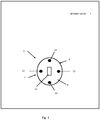
Figure 1 is a schematic representation of a defibrillator comprising a first embodiment of an activation mechanism according to the invention, and -
Figure 2 is a schematic representation of a defibrillator comprising a second embodiment of an activation mechanism according to the invention. - Referring to
Figure 1 , adefibrillator 1 comprises anactivation mechanism 3. Theactivation mechanism 3 comprises anactivator 5 and astatus indicator 7. It will be appreciated that the defibrillator comprises other components such as electrodes, defibrillation shock circuitry, etc. which are not shown. - The
activator 5 comprises a button 9 and asign 11 disposed on an outer surface of the button 9 of theactivator 5. Theactivator 5 further comprises a single, elongate light (not shown). The light is contained within theactivator 5 at a substantially central position of the button 9, to provide back lighting of thesign 11 on the outer surface of the button 9 of theactivator 5. In this embodiment, the light uses an illumination pattern comprising repeated increasing of the illumination of the light from a minimum illumination to a maximum illumination and decreasing of the illumination of the light from the maximum illumination to the minimum illumination. It will be appreciated that other illumination patterns may be used. The illuminatedsign 11 indicates the button 9 of theactivator 5 to a user of thedefibrillator 1, so that the user can easily distinguish theactivator 5 from other controls of thedefibrillator 1. - The
status indicator 7 comprises fourlights 13 provided on an outer surface of theactivation mechanism 3 and arranged in an approximately diamond shape, as shown. Thelights 13 are illuminated green in the first mode of thestatus indication device 7 which indicates the 'defibrillator ready' status of thedefibrillator 1. Thelights 13 are illuminated red in a second mode of thestatus indication device 7 which indicates the 'defibrillator not ready' status of thedefibrillator 1. In this embodiment, thelights 13 are illuminated and remain illuminated for a pre-determined period of time. It will be appreciated that other illumination patterns may be used. - When a user needs to use the
defibrillator 1, they first check if thelights 13 of thestatus indicator 7 are green. If this is the case, the user presses the button 9 of theactivator 5. This causes the button 9 of theactivator 5 to be disposed in the second condition in which thedefibrillator 1 is activated. - As the
activation mechanism 3 comprises theactivator 5 and thestatus indicator 7, the user is not confused by a separate status indication device, mistaking this for an activation device, and is able to use theactivator 5 of theactivation mechanism 3 promptly. - Referring to
Figure 2 , adefibrillator 21 comprises anactivation mechanism 23. Theactivation mechanism 23 comprises anactivator 25 and astatus indicator 27. It will be appreciated that the defibrillator comprises other components such as electrodes, defibrillation shock circuitry, etc. which are not shown. - The
activator 25 comprises abutton 29 and asign 31 disposed on an outer surface of thebutton 29 of theactivator 25. Thestatus indicator 27 comprises a single, elongate light (not shown). The light is contained within theactivator 25 at a substantially central position of thebutton 29, to provide back lighting of thesign 31 on the outer surface of thebutton 29 of theactivator 25. The light of thestatus indicator 27 is illuminated green in the first mode of thestatus indication device 27 which indicates the 'defibrillator ready' status of thedefibrillator 21. The light of thestatus indicator 27 is illuminated red in a second mode of thestatus indication device 7 which indicates the 'defibrillator not ready' status of thedefibrillator 21. In this embodiment, the light of thestatus indicator 27 is illuminated and remain illuminated for a pre-determined period of time. It will be appreciated that other illumination patterns may be used. The illuminatedsign 11 indicates the button 9 of theactivator 5 to a user of thedefibrillator 1, so that the user can easily distinguish theactivator 5 from other controls of thedefibrillator 1. The illuminatedsign 11 also indicates the status of thedefibrillator 21 to the user. - When a user needs to use the
defibrillator 21, they first check if the light of thestatus indicator 27, which back lights thesign 31, is green. If this is the case, the user presses thebutton 29 of theactivator 25. This causes thebutton 29 of theactivator 25 to be disposed in the second condition in which thedefibrillator 1 is activated. - As the
activation mechanism 23 comprises theactivator 25 and thestatus indicator 27, the user is not confused by a separate status indication device, mistaking this for an activation device, and is able to use theactivator 25 of theactivation mechanism 23 promptly.
Claims (15)
- A defibrillator comprising an activation mechanism having an activator and a status indicator wherein the activator is disposable in a first condition in which the defibrillator is deactivated and in a second condition in which the defibrillator is activated and the status indicator is operable in at least a first mode in which a 'defibrillator ready' status of the defibrillator is indicated and a second mode in which a 'defibrillator not ready' status of the defibrillator is indicated.
- A defibrillator according to claim 1 in which the status indicator comprises one or more lights.
- A defibrillator according to claim 2 in which the one or more lights of the status indicator are illuminated a first colour in the first mode in which the 'defibrillator ready' status of the defibrillator is indicated and are illuminated a second colour in the second mode in which the 'defibrillator not ready' status of the defibrillator is indicated.
- A defibrillator according to claim 2 or claim 3 in which, in either the first mode or the second mode of the defibrillator or both the first mode and the second mode of the defibrillator, the one or more lights of the status indicator are illuminated in an illumination pattern.
- A defibrillator according to any preceding claim in which the activator is disposable in the first condition and the second condition by being movable between a first position in which the defibrillator is deactivated and a second position in which the defibrillator is activated.
- A defibrillator according to claim 5 in which the activator comprises any of a button, a hook, a dial, a slider, a handle, a knob, a key, a switch.
- A defibrillator according to any preceding claim in which the activator comprises a sign which indicates the activator to a user of the defibrillator.
- A defibrillator according to claim 7 in which the activator comprises one or more lights which illuminate the sign of the activator.
- A defibrillator according to claim 2 or claim 8 in which the one or more lights are contained within the activation mechanism.
- A defibrillator according to claim 2 or claim 8 in which the one or more lights are provided on an outer surface of the activation mechanism.
- A defibrillator according to claim 9 or claim 10 in which the one or more lights are illuminated in an illumination pattern.
- A defibrillator according to claim 11 in which the illumination pattern comprises continued illumination of the one or more lights for a pre-determined period of time.
- A defibrillator according to claim 11 in which the illumination pattern comprises repeated flashing of the one or more lights.
- A defibrillator according to claim 11 in which the illumination pattern comprises repeated increasing of the illumination of the one or more lights from a minimum illumination to a maximum illumination and decreasing of the illumination of the one or more lights from the maximum illumination to the minimum illumination.
- A defibrillator according to claim 11 in which the illumination pattern comprises repeated increasing of the illumination of the one or more lights from a minimum illumination to a maximum illumination at a first speed and decreasing of the illumination of the one or more lights from the maximum illumination to the minimum illumination at a second, slower, speed.
Applications Claiming Priority (1)
| Application Number | Priority Date | Filing Date | Title |
|---|---|---|---|
| GBGB1721767.0A GB201721767D0 (en) | 2017-12-22 | 2017-12-22 | Defibrillator status indication and activation |
Publications (1)
| Publication Number | Publication Date |
|---|---|
| EP3501598A1 true EP3501598A1 (en) | 2019-06-26 |
Family
ID=61131452
Family Applications (1)
| Application Number | Title | Priority Date | Filing Date |
|---|---|---|---|
| EP18214278.6A Withdrawn EP3501598A1 (en) | 2017-12-22 | 2018-12-19 | Defibrillator status indication and activation |
Country Status (5)
| Country | Link |
|---|---|
| US (1) | US11565120B2 (en) |
| EP (1) | EP3501598A1 (en) |
| JP (1) | JP2019111329A (en) |
| AU (1) | AU2018278898B2 (en) |
| GB (2) | GB201721767D0 (en) |
Citations (7)
| Publication number | Priority date | Publication date | Assignee | Title |
|---|---|---|---|---|
| US20040133244A1 (en) * | 2001-09-21 | 2004-07-08 | Vaisnys Gintaras A. | Automatic external defibrillator with active status indicator |
| WO2005039408A1 (en) * | 2003-10-28 | 2005-05-06 | A & D Company, Ltd. | Electronic blood pressure meter |
| US20060142806A1 (en) * | 2004-12-27 | 2006-06-29 | Koninklijke Philips Electronics N.V. | Method and article for storing an automatic external defibrillator for use without a prescription |
| US20080136652A1 (en) * | 2006-03-21 | 2008-06-12 | Defibtech, Llc | System and Method for Effectively Indicating Element Failure or a Preventive Maintenance Condition in an Automatic External Defibrillator (AED) |
| US20090254136A1 (en) * | 2004-12-20 | 2009-10-08 | Koninklijke Philips Electronics N.V. | Automatic External Defibrillator for Adult and Pediatric Patients |
| EP2408521A2 (en) * | 2009-03-17 | 2012-01-25 | Cardio Thrive, Inc | External defibrillator |
| US20120123491A1 (en) * | 2010-11-15 | 2012-05-17 | William Tom Hunter | Defibrillator device with status indicating transport handle |
Family Cites Families (21)
| Publication number | Priority date | Publication date | Assignee | Title |
|---|---|---|---|---|
| WO1995002365A1 (en) * | 1993-07-17 | 1995-01-26 | Gerhard Schad | Surgical instrument |
| US5904707A (en) * | 1997-08-15 | 1999-05-18 | Heartstream, Inc. | Environment-response method for maintaining an external medical device |
| US5929601A (en) * | 1997-12-22 | 1999-07-27 | Lifecor, Inc. | Battery management apparatus for portable electronic devices |
| US6169387B1 (en) * | 1997-12-22 | 2001-01-02 | Lifecor, Inc. | Battery management apparatus for portable electronic devices |
| ATE273048T1 (en) * | 1999-02-08 | 2004-08-15 | Heartsine Technologies Ltd | DEVICE FOR DETERMINING WHETHER A PATIENT IS SUSPENSIVE TO DEFIBRILLATION |
| US20030208237A1 (en) * | 2002-05-06 | 2003-11-06 | Medtronic Physio-Control Manufacturing Corp. | Single-action method of activating and exposing user interface of medical device |
| US8527044B2 (en) * | 2002-05-15 | 2013-09-03 | Physio-Control, Inc. | User interface method and apparatus for a medical device |
| US7706878B2 (en) * | 2004-05-07 | 2010-04-27 | Zoll Medical Corporation | Automated caregiving device with prompting based on caregiver progress |
| US20100023074A1 (en) * | 2004-12-27 | 2010-01-28 | Koninklijke Philips Electronics N.V. | Method and Apparatus for Contacting an Over-the-Counter Automatic External Defibrillator |
| US20070270909A1 (en) * | 2006-05-22 | 2007-11-22 | Saketkhou B Benjamin | Wireless communication device with integrated defibrillator |
| US8914104B2 (en) * | 2009-11-30 | 2014-12-16 | Zoll Medical Corporation | Dual-mode defibrillator with latched panel |
| JP2012235874A (en) * | 2011-05-11 | 2012-12-06 | Hitachi Kokusai Electric Inc | Aed |
| US10105546B2 (en) * | 2012-05-08 | 2018-10-23 | Physio-Control, Inc. | Utility module |
| US9375584B2 (en) * | 2012-05-22 | 2016-06-28 | Physio-Control, Inc. | Medical device with lack-of-readiness alarm |
| CN104994907B (en) * | 2012-12-26 | 2017-07-18 | 皇家飞利浦有限公司 | Intuitive overlay readiness indicator for defibrillators |
| RU2685739C2 (en) * | 2014-03-27 | 2019-04-23 | Конинклейке Филипс Н.В. | Encoded status indicator for automatic external defibrillators |
| US9929584B2 (en) * | 2014-10-30 | 2018-03-27 | Boston Scientific Neuromodulation Corporation | External charging coil assembly for charging a medical device |
| US10099061B2 (en) * | 2014-11-25 | 2018-10-16 | Physio-Control, Inc. | Emergency apparatus indicator |
| EP3229896B1 (en) * | 2014-12-12 | 2022-08-03 | Koninklijke Philips N.V. | Automated external defibrillator (aed) with dual ecg analysis algorithms |
| CN205215211U (en) * | 2015-11-23 | 2016-05-11 | 长江大学 | Activity of heart electricity detects defibrillator |
| JP7193864B2 (en) * | 2016-12-19 | 2022-12-21 | ハートヒーロー, インコーポレイテッド | Automated External Defibrillators and Methods of Use |
-
2017
- 2017-12-22 GB GBGB1721767.0A patent/GB201721767D0/en not_active Ceased
-
2018
- 2018-12-12 AU AU2018278898A patent/AU2018278898B2/en active Active
- 2018-12-13 US US16/219,377 patent/US11565120B2/en active Active
- 2018-12-17 JP JP2018235089A patent/JP2019111329A/en active Pending
- 2018-12-19 EP EP18214278.6A patent/EP3501598A1/en not_active Withdrawn
- 2018-12-19 GB GB1820761.3A patent/GB2570798A/en not_active Withdrawn
Patent Citations (7)
| Publication number | Priority date | Publication date | Assignee | Title |
|---|---|---|---|---|
| US20040133244A1 (en) * | 2001-09-21 | 2004-07-08 | Vaisnys Gintaras A. | Automatic external defibrillator with active status indicator |
| WO2005039408A1 (en) * | 2003-10-28 | 2005-05-06 | A & D Company, Ltd. | Electronic blood pressure meter |
| US20090254136A1 (en) * | 2004-12-20 | 2009-10-08 | Koninklijke Philips Electronics N.V. | Automatic External Defibrillator for Adult and Pediatric Patients |
| US20060142806A1 (en) * | 2004-12-27 | 2006-06-29 | Koninklijke Philips Electronics N.V. | Method and article for storing an automatic external defibrillator for use without a prescription |
| US20080136652A1 (en) * | 2006-03-21 | 2008-06-12 | Defibtech, Llc | System and Method for Effectively Indicating Element Failure or a Preventive Maintenance Condition in an Automatic External Defibrillator (AED) |
| EP2408521A2 (en) * | 2009-03-17 | 2012-01-25 | Cardio Thrive, Inc | External defibrillator |
| US20120123491A1 (en) * | 2010-11-15 | 2012-05-17 | William Tom Hunter | Defibrillator device with status indicating transport handle |
Also Published As
| Publication number | Publication date |
|---|---|
| JP2019111329A (en) | 2019-07-11 |
| GB201721767D0 (en) | 2018-02-07 |
| US20190192869A1 (en) | 2019-06-27 |
| US11565120B2 (en) | 2023-01-31 |
| AU2018278898B2 (en) | 2024-03-21 |
| GB2570798A (en) | 2019-08-07 |
| GB201820761D0 (en) | 2019-01-30 |
| AU2018278898A1 (en) | 2019-07-11 |
Similar Documents
| Publication | Publication Date | Title |
|---|---|---|
| US11887451B2 (en) | Hazard detector with optical status indicator | |
| US7819544B2 (en) | Pressure activated lighted glove | |
| US6278372B1 (en) | Methods and apparatus for promoting hygiene | |
| US10825313B2 (en) | Hazard detector with optical status indicator | |
| TW200634256A (en) | Switch with light control function | |
| US20210158663A1 (en) | Hazard detector with optical status indicator | |
| US20170365136A1 (en) | Mobile Emergency Light Device | |
| US20140139353A1 (en) | Indicator system | |
| US10352512B1 (en) | Device for illuminating a door knob keyhole | |
| WO2014066917A1 (en) | A security device | |
| JP2017226211A5 (en) | ||
| AU2018278898B2 (en) | Defibrillator activation and status indication | |
| KR101186460B1 (en) | Led lamp for illumination lamp with lantern and control method thereof | |
| AU2013100505A4 (en) | Power Outlet Socket Sensor Switch | |
| TW202128463A (en) | Smart lighting foot mat | |
| US10529507B2 (en) | Automation control device | |
| KR101036154B1 (en) | Multi-purpose ID card for disaster alert recognition | |
| GB2400959A (en) | Personal possessions protector | |
| US8269621B2 (en) | Mezuzah case | |
| CN220509706U (en) | Switch panel controlled by voice | |
| CN212574185U (en) | Improved downhole operation safety belt | |
| US20260014016A1 (en) | Device for lengthening and/or straightening a penis | |
| JP3191692U (en) | Light emitting device | |
| CN201215680Y (en) | Electronic prompter | |
| TWM599805U (en) | Elevator car control device |
Legal Events
| Date | Code | Title | Description |
|---|---|---|---|
| PUAI | Public reference made under article 153(3) epc to a published international application that has entered the european phase |
Free format text: ORIGINAL CODE: 0009012 |
|
| STAA | Information on the status of an ep patent application or granted ep patent |
Free format text: STATUS: THE APPLICATION HAS BEEN PUBLISHED |
|
| AK | Designated contracting states |
Kind code of ref document: A1 Designated state(s): AL AT BE BG CH CY CZ DE DK EE ES FI FR GB GR HR HU IE IS IT LI LT LU LV MC MK MT NL NO PL PT RO RS SE SI SK SM TR |
|
| AX | Request for extension of the european patent |
Extension state: BA ME |
|
| STAA | Information on the status of an ep patent application or granted ep patent |
Free format text: STATUS: REQUEST FOR EXAMINATION WAS MADE |
|
| 17P | Request for examination filed |
Effective date: 20191220 |
|
| RBV | Designated contracting states (corrected) |
Designated state(s): AL AT BE BG CH CY CZ DE DK EE ES FI FR GB GR HR HU IE IS IT LI LT LU LV MC MK MT NL NO PL PT RO RS SE SI SK SM TR |
|
| STAA | Information on the status of an ep patent application or granted ep patent |
Free format text: STATUS: EXAMINATION IS IN PROGRESS |
|
| 17Q | First examination report despatched |
Effective date: 20210205 |
|
| P01 | Opt-out of the competence of the unified patent court (upc) registered |
Effective date: 20230829 |
|
| RAP1 | Party data changed (applicant data changed or rights of an application transferred) |
Owner name: STRYKER EUROPEAN OPERATIONS LIMITED |
|
| STAA | Information on the status of an ep patent application or granted ep patent |
Free format text: STATUS: THE APPLICATION HAS BEEN WITHDRAWN |
|
| 18W | Application withdrawn |
Effective date: 20260105 |