EP3501440B1 - Bipolar electrode probe - Google Patents
Bipolar electrode probe Download PDFInfo
- Publication number
- EP3501440B1 EP3501440B1 EP18165102.7A EP18165102A EP3501440B1 EP 3501440 B1 EP3501440 B1 EP 3501440B1 EP 18165102 A EP18165102 A EP 18165102A EP 3501440 B1 EP3501440 B1 EP 3501440B1
- Authority
- EP
- European Patent Office
- Prior art keywords
- conductive
- opening
- electrode probe
- sleeve
- area
- Prior art date
- Legal status (The legal status is an assumption and is not a legal conclusion. Google has not performed a legal analysis and makes no representation as to the accuracy of the status listed.)
- Active
Links
Images




Classifications
-
- A—HUMAN NECESSITIES
- A61—MEDICAL OR VETERINARY SCIENCE; HYGIENE
- A61B—DIAGNOSIS; SURGERY; IDENTIFICATION
- A61B18/00—Surgical instruments, devices or methods for transferring non-mechanical forms of energy to or from the body
- A61B18/04—Surgical instruments, devices or methods for transferring non-mechanical forms of energy to or from the body by heating
- A61B18/12—Surgical instruments, devices or methods for transferring non-mechanical forms of energy to or from the body by heating by passing a current through the tissue to be heated, e.g. high-frequency current
- A61B18/14—Probes or electrodes therefor
- A61B18/1477—Needle-like probes
-
- A—HUMAN NECESSITIES
- A61—MEDICAL OR VETERINARY SCIENCE; HYGIENE
- A61B—DIAGNOSIS; SURGERY; IDENTIFICATION
- A61B18/00—Surgical instruments, devices or methods for transferring non-mechanical forms of energy to or from the body
- A61B18/04—Surgical instruments, devices or methods for transferring non-mechanical forms of energy to or from the body by heating
- A61B18/12—Surgical instruments, devices or methods for transferring non-mechanical forms of energy to or from the body by heating by passing a current through the tissue to be heated, e.g. high-frequency current
- A61B18/14—Probes or electrodes therefor
-
- A—HUMAN NECESSITIES
- A61—MEDICAL OR VETERINARY SCIENCE; HYGIENE
- A61B—DIAGNOSIS; SURGERY; IDENTIFICATION
- A61B18/00—Surgical instruments, devices or methods for transferring non-mechanical forms of energy to or from the body
- A61B2018/00005—Cooling or heating of the probe or tissue immediately surrounding the probe
- A61B2018/00011—Cooling or heating of the probe or tissue immediately surrounding the probe with fluids
- A61B2018/00029—Cooling or heating of the probe or tissue immediately surrounding the probe with fluids open
-
- A—HUMAN NECESSITIES
- A61—MEDICAL OR VETERINARY SCIENCE; HYGIENE
- A61B—DIAGNOSIS; SURGERY; IDENTIFICATION
- A61B18/00—Surgical instruments, devices or methods for transferring non-mechanical forms of energy to or from the body
- A61B2018/00053—Mechanical features of the instrument of device
- A61B2018/00059—Material properties
- A61B2018/00071—Electrical conductivity
-
- A—HUMAN NECESSITIES
- A61—MEDICAL OR VETERINARY SCIENCE; HYGIENE
- A61B—DIAGNOSIS; SURGERY; IDENTIFICATION
- A61B18/00—Surgical instruments, devices or methods for transferring non-mechanical forms of energy to or from the body
- A61B2018/00053—Mechanical features of the instrument of device
- A61B2018/00059—Material properties
- A61B2018/00071—Electrical conductivity
- A61B2018/00077—Electrical conductivity high, i.e. electrically conducting
-
- A—HUMAN NECESSITIES
- A61—MEDICAL OR VETERINARY SCIENCE; HYGIENE
- A61B—DIAGNOSIS; SURGERY; IDENTIFICATION
- A61B18/00—Surgical instruments, devices or methods for transferring non-mechanical forms of energy to or from the body
- A61B2018/00053—Mechanical features of the instrument of device
- A61B2018/00059—Material properties
- A61B2018/00071—Electrical conductivity
- A61B2018/00083—Electrical conductivity low, i.e. electrically insulating
-
- A—HUMAN NECESSITIES
- A61—MEDICAL OR VETERINARY SCIENCE; HYGIENE
- A61B—DIAGNOSIS; SURGERY; IDENTIFICATION
- A61B18/00—Surgical instruments, devices or methods for transferring non-mechanical forms of energy to or from the body
- A61B2018/00315—Surgical instruments, devices or methods for transferring non-mechanical forms of energy to or from the body for treatment of particular body parts
- A61B2018/00541—Lung or bronchi
-
- A—HUMAN NECESSITIES
- A61—MEDICAL OR VETERINARY SCIENCE; HYGIENE
- A61B—DIAGNOSIS; SURGERY; IDENTIFICATION
- A61B18/00—Surgical instruments, devices or methods for transferring non-mechanical forms of energy to or from the body
- A61B2018/00571—Surgical instruments, devices or methods for transferring non-mechanical forms of energy to or from the body for achieving a particular surgical effect
- A61B2018/00577—Ablation
-
- A—HUMAN NECESSITIES
- A61—MEDICAL OR VETERINARY SCIENCE; HYGIENE
- A61B—DIAGNOSIS; SURGERY; IDENTIFICATION
- A61B18/00—Surgical instruments, devices or methods for transferring non-mechanical forms of energy to or from the body
- A61B18/04—Surgical instruments, devices or methods for transferring non-mechanical forms of energy to or from the body by heating
- A61B18/12—Surgical instruments, devices or methods for transferring non-mechanical forms of energy to or from the body by heating by passing a current through the tissue to be heated, e.g. high-frequency current
- A61B18/1206—Generators therefor
- A61B2018/1246—Generators therefor characterised by the output polarity
- A61B2018/126—Generators therefor characterised by the output polarity bipolar
-
- A—HUMAN NECESSITIES
- A61—MEDICAL OR VETERINARY SCIENCE; HYGIENE
- A61B—DIAGNOSIS; SURGERY; IDENTIFICATION
- A61B18/00—Surgical instruments, devices or methods for transferring non-mechanical forms of energy to or from the body
- A61B18/04—Surgical instruments, devices or methods for transferring non-mechanical forms of energy to or from the body by heating
- A61B18/12—Surgical instruments, devices or methods for transferring non-mechanical forms of energy to or from the body by heating by passing a current through the tissue to be heated, e.g. high-frequency current
- A61B18/14—Probes or electrodes therefor
- A61B2018/1472—Probes or electrodes therefor for use with liquid electrolyte, e.g. virtual electrodes
-
- A—HUMAN NECESSITIES
- A61—MEDICAL OR VETERINARY SCIENCE; HYGIENE
- A61B—DIAGNOSIS; SURGERY; IDENTIFICATION
- A61B18/00—Surgical instruments, devices or methods for transferring non-mechanical forms of energy to or from the body
- A61B18/04—Surgical instruments, devices or methods for transferring non-mechanical forms of energy to or from the body by heating
- A61B18/12—Surgical instruments, devices or methods for transferring non-mechanical forms of energy to or from the body by heating by passing a current through the tissue to be heated, e.g. high-frequency current
- A61B18/14—Probes or electrodes therefor
- A61B2018/1497—Electrodes covering only part of the probe circumference
-
- A—HUMAN NECESSITIES
- A61—MEDICAL OR VETERINARY SCIENCE; HYGIENE
- A61B—DIAGNOSIS; SURGERY; IDENTIFICATION
- A61B2218/00—Details of surgical instruments, devices or methods for transferring non-mechanical forms of energy to or from the body
- A61B2218/001—Details of surgical instruments, devices or methods for transferring non-mechanical forms of energy to or from the body having means for irrigation and/or aspiration of substances to and/or from the surgical site
- A61B2218/002—Irrigation
Definitions
- unipolar electrode probe In terms of RFA (Radiofrequency Ablation) electrode probes used for clinical purposes, at present unipolar electrode probe is the most commonly used type. However, such a unipolar electrode probe system has a large ablation range and therefore may easily burn the normal superficial skin when used to treat lesions right underneath the skin. The unipolar electrode probe system may also put patients having heart disease or carrying pacemakers, pregnant women, and fetuses at risk.
- RFA Radiofrequency Ablation
- the bipolar electrode probe As an attempt to solve the aforementioned problems of the unipolar electrode probe, the bipolar electrode probe has been proposed for clinical uses. Nevertheless, the existing bipolar electrode probe still faces the following problems.
- the bipolar electrode probe is formed by coupling the active electrode, the insulation layer, and the passive electrode, but the mechanical strength may be weak at the junction and the probe may easily break during operation, or the cooling water inside may leak from the junction.
- the length of the ablation region cannot be adjusted. Generally, the length of the conductive region of the bipolar electrode probe is designed to be about 0.9cm and thus the bipolar electrode probe cannot be used to ablate a target tissue of 0.9cm or shorter.
- Third, for the bipolar electrode probe it is required to dispose electrically isolated conductive wires and solder joints inside. For this reason, the bipolar electrode probe has a complicated structure and is difficult to manufacture and be made compact.
- the electrosurgical probe includes a first treatment element at a distal end of the probe, wherein the first treatment element being in electrical connection with a power supply.
- the first treatment element is slidably disposed within the longitudinal bore so that the first treatment element is advanced radially outward from the window and shaft to affect treatment of the intraosseous nerve within the cancellous bone region.
- Document US 2015/173827 discloses an electrosurgical device having a tubular outer shaft and an inner shaft.
- the tubular outer shaft includes an axis and a distal end region.
- the distal end region includes a distal-most tip and a cutting edge defining a window in the outer shaft proximal along the axis to the distal-most tip.
- a small longitudinal electric field may be formed from the conductive needle 110 to the conductive sleeve 130 via the first opening 122 and the second opening 132 along the longitudinal direction x, but the influence thereof may be ignored and thus is not discussed here.
- the conductive needle 110 serves as an active electrode while the conductive sleeve 130 serves as a passive electrode, for example, but the disclosure is not limited thereto.
- the conductive needle 110 may serve as the passive electrode and the conductive sleeve 130 may serve as the active electrode.
- the bipolar electrode probe 100 has a front ablation region and a rear ablation region. Specifically, the longitudinal electric field E1 at the front is for ablating a front section of the target tissue, and the transverse electric field E2 at the rear is for ablating a rear section of the target tissue.
- An embodiment of the structure of the bipolar electrode probe 100 will be described hereinafter.
- the longitudinal insulation distance dx is from a front end of the second opening 132 to a front end of the first opening 122 along the longitudinal direction x.
- the transverse insulation distance dy is from one end of the second opening 132 to one end of the first opening 122 on the same side along the transverse direction y.
- the longitudinal insulation distance dx is to ensure the longitudinal isolation distance between the conductive needle 110 and the conductive sleeve 130, so as to prevent a large current from flowing through the tissue due to a short isolation distance.
- the transverse insulation distance dy ensures the transverse isolation distance between the conductive needle 110 and the conductive sleeve 130, so as to maintain a current path that is sufficient for generating the transverse electric field E2 and prevent reduction of the ablation range due to a short current path.
- a ratio of the area of the conductive needle 110 exposed by the first opening 122 to the area of the conductive sleeve 130 in the region outside the second opening 132 is 1:0.9 to 1:1.1.
- the area of the conductive needle 110 is L1 ⁇ W1, wherein L1 is a length of the conductive needle 110 along the longitudinal direction x and W1 is a length of the conductive needle 110 in a circumferential direction; moreover, the area of the conductive sleeve 130 is L2 ⁇ W2, wherein L2 is a length of the conductive sleeve 130 along the longitudinal direction x and W2 is a length of the conductive sleeve 130 in the circumferential direction.
- the area of the conductive needle 110 may be equal to the area of the conductive sleeve 130, so as to generate the transverse electric field E2 uniformly.
- the transverse electric field E2 may be generated uniformly.
- a ratio of the area of a conductive region where the longitudinal electric field E1 exists to the area of a conductive region where the transverse electric field E2 exists is 1:2.1 to 1:2.6.
- the front ablation region (the longitudinal electric field E1) and the rear ablation region (the transverse electric field E2) of the bipolar electrode probe 100 may be set to a proper ratio.
- the longitudinal insulation distance dx and the transverse insulation distance dy define an insulation area
- the area of the conductive needle 110 exposed by the first opening 122 and the area of the conductive sleeve 130 outside the second opening 132 define a conductive area
- a ratio of the insulation area to the conductive area is 1:8 to 1:44.
- the insulation area is the area of the insulation layer 120 that exists in the region of the longitudinal insulation distance dx and the transverse insulation distance dy.
- the conductive area is a sum of the area L1 ⁇ W1 of the conductive needle 110 and the area L2 ⁇ W2 of the conductive sleeve 130. Through calculation, it is obtained that the ratio of the insulation area to the conductive area is 1:8 to 1:44. With this setting, the transverse electric field E2 is generated uniformly, so as to perform uniform ablation.
- FIG. 4A and FIG. 4B are schematic views showing that the insulation sleeve moves back and forth along the longitudinal direction according to another embodiment of the disclosure.
- the insulation sleeve 140 is configured to be movable back and forth along the longitudinal direction x.
- the larger transverse electric field E2 changes to a smaller transverse electric field E2'.
- the range of the transverse electric field E2 may be adjusted by moving the insulation sleeve 140 back and forth along the longitudinal direction x.
- the insulation sleeve 140 may be moved to completely close the transverse electric field E2 and to only use the longitudinal electric field E1 for ablation, so as to prevent burning the epidermis of the patient.
- the range of the transverse electric field E2 is reduced to achieve a smaller ablation region; on the other hand, when the insulation sleeve 140 is moved toward the rear end of the bipolar electrode probe 100, the range of the transverse electric field E2 is increased to achieve a larger ablation region.
- the strength of the transverse electric field E2 in the transverse direction y remains uniform. Therefore, the ablation region is maintained uniform in the transverse direction y.
- the number of the first openings 122 may be equal to the number of the second openings 132.
- the number of the first openings 122 is one or more, and the number of the second openings 132 is one or more.
- an electrode pair is formed (as shown in FIG. 3B ).
- the number of the first openings 122 and the number of the second openings 132 may be two, three, four, five, six, and so on, respectively.
- FIG. 5 is a schematic view of the bipolar electrode probe according to another embodiment of the disclosure.
- FIG. 6A is a schematic cross-sectional view taken along the plane O of FIG. 5 .
- FIG. 6B is a schematic cross-sectional view taken along the plane P of FIG. 5 .
- FIG. 6C is a schematic cross-sectional view taken along the plane Q of FIG. 5 .
- identical components are represented by identical reference numerals as shown in FIG. 1 to FIG. 4B , and therefore detailed descriptions thereof are not repeated hereinafter.
- the number of the first openings 122 is four and the number of the second openings 132 is four, so as to form four electrode pairs (as shown in FIG. 6B ).
- FIG. 7 is a partially enlarged view of the bipolar electrode probe of FIG. 5 .
- the region exposed by the insulation layer 120 has the longitudinal insulation distance dx and the transverse insulation distance dy.
- the longitudinal insulation distance dx is to ensure the longitudinal isolation distance between the conductive needle 110 and the conductive sleeve 130 in the longitudinal direction, so as to prevent a large current from flowing through the tissue due to a short isolation distance.
- the transverse insulation distance dy is maintained to ensure the transverse isolation distance between the conductive needle 110 and the conductive sleeve 130, so as to maintain a current path that is sufficient for generating the transverse electric field E2 and prevent reduction of the ablation range due to a short current path.
- FIG. 8 is a partially enlarged view of the bipolar electrode probe of FIG. 5 . Similar to the description of FIG. 3B , as shown in FIG. 8 , in the region of the transverse electric field E2, the area of the conductive needle 110 may be equal to the area of the conductive sleeve 130, so as to generate the transverse electric field E2 uniformly. In another embodiment, when the ratio of the area of the conductive needle 110 to the area of the conductive sleeve 130 is set to 1:0.9 to 1:1.1, the transverse electric field E2 may be generated uniformly.
- FIG. 9 is a schematic view of the bipolar electrode probe according to another embodiment of the disclosure. Components identical to those in the above embodiments of FIG. 1 to FIG. 8 are represented by identical reference numerals, and therefore detailed descriptions thereof are not repeated hereinafter.
- a bipolar electrode probe 104 of this embodiment may further include: an infusion member 150 disposed at the rear ends of the insulation layer 120 and the conductive sleeve 130. The infusion member 150 is disposed to allow a liquid substance L to pass through a gap between the insulation layer 120 and the conductive sleeve 130 to be outputted from the first opening 122 and the second opening 132.
- the liquid substance L enters the gap between the insulation layer 120 and the conductive sleeve 130 in the direction indicated by the arrow and flows out from the first opening 122 and the second opening 132 at the front to be infused into the target tissue.
- the liquid substance L may be: an anesthetic drug for easing pain in the ablation region or physiological saline for increasing the volume of ablation.
- physiological saline for increasing the volume of ablation.
- the infusion member 150 may further include sealing members 152 disposed at a junction between the infusion member 150 and the insulation layer 120 and a junction between the infusion member 150 and the conductive sleeve 130, so as to properly assemble the infusion member 150 to the bipolar electrode probe 104 and enable the liquid substance L to be properly inputted into the inlet of the infusion member 150, and then through the gap between the insulation layer 120 and the conductive sleeve 130, to be outputted to the target tissue from the first opening 122 and the second opening 132.
- the infusion member 150 is assembled to the bipolar electrode probe 104 that has four first openings 122 and four second openings 132; however, the infusion member 150 may also be assembled to the bipolar electrode probe 100 that has one first opening 122 and one second opening 132, as shown in FIG. 3A .
- the unipolar electrode probe forms an ablation region of 9mm in the longitudinal direction and an ablation region of 4mm in the transverse direction
- the bipolar electrode probe 100 forms an ablation region of 6mm in the longitudinal direction and an ablation region of 4mm in the transverse direction, which at least achieves an ablation effect similar to the unipolar electrode probe.
- the length of the ablation region formed by the unipolar electrode probe in the longitudinal direction is 9mm, which exceeds the target length 7mm and the operation accuracy drops.
- the length of the ablation region formed by the bipolar electrode probe 100 of the disclosure in the longitudinal direction is 6mm, which is close to the target length 7mm and achieves favorable operation accuracy.
- the unipolar electrode probe forms an ablation region of 11mm in the longitudinal direction and an ablation region of 4mm in the transverse direction;
- the bipolar electrode probe 100 according to the embodiments of the disclosure forms an ablation region of 11mm in the longitudinal direction and an ablation region of 4.5mm in the transverse direction, which at least achieves an ablation effect similar to the unipolar electrode probe.
Landscapes
- Health & Medical Sciences (AREA)
- Engineering & Computer Science (AREA)
- Life Sciences & Earth Sciences (AREA)
- Surgery (AREA)
- Animal Behavior & Ethology (AREA)
- Public Health (AREA)
- Veterinary Medicine (AREA)
- General Health & Medical Sciences (AREA)
- Biomedical Technology (AREA)
- Heart & Thoracic Surgery (AREA)
- Medical Informatics (AREA)
- Molecular Biology (AREA)
- Physics & Mathematics (AREA)
- Plasma & Fusion (AREA)
- Otolaryngology (AREA)
- Nuclear Medicine, Radiotherapy & Molecular Imaging (AREA)
- Surgical Instruments (AREA)
- Anesthesiology (AREA)
- Hematology (AREA)
Description
- The disclosure relates to an electrode probe and more particularly relates to a bipolar electrode probe.
- In terms of RFA (Radiofrequency Ablation) electrode probes used for clinical purposes, at present unipolar electrode probe is the most commonly used type. However, such a unipolar electrode probe system has a large ablation range and therefore may easily burn the normal superficial skin when used to treat lesions right underneath the skin. The unipolar electrode probe system may also put patients having heart disease or carrying pacemakers, pregnant women, and fetuses at risk.
- As an attempt to solve the aforementioned problems of the unipolar electrode probe, the bipolar electrode probe has been proposed for clinical uses. Nevertheless, the existing bipolar electrode probe still faces the following problems. First, the bipolar electrode probe is formed by coupling the active electrode, the insulation layer, and the passive electrode, but the mechanical strength may be weak at the junction and the probe may easily break during operation, or the cooling water inside may leak from the junction. Second, for the bipolar electrode probe, the length of the ablation region cannot be adjusted. Generally, the length of the conductive region of the bipolar electrode probe is designed to be about 0.9cm and thus the bipolar electrode probe cannot be used to ablate a target tissue of 0.9cm or shorter. Third, for the bipolar electrode probe, it is required to dispose electrically isolated conductive wires and solder joints inside. For this reason, the bipolar electrode probe has a complicated structure and is difficult to manufacture and be made compact.
- In view of the above, how to design a bipolar electrode probe that has a simple structure and an adjustable ablation range is an issue that needs to be addressed in this field.
DocumentUS 2015/057658 discloses a method and apparatus for treating an intraosseous nerve. The method includes positioning a hollow shaft through the cortical shell of a vertebral body and into a cancellous bone region of the vertebral body. The hollow shaft includes an annular wall having a longitudinal bore therein, a proximal portion and a distal portion, and a first window extending transversely through the annular wall. An electrosurgical probe is advanced within the longitudinal bore from the proximal portion toward the distal portion. The electrosurgical probe includes a first treatment element at a distal end of the probe, wherein the first treatment element being in electrical connection with a power supply. The first treatment element is slidably disposed within the longitudinal bore so that the first treatment element is advanced radially outward from the window and shaft to affect treatment of the intraosseous nerve within the cancellous bone region.
DocumentUS 2015/173827 discloses an electrosurgical device having a tubular outer shaft and an inner shaft. The tubular outer shaft includes an axis and a distal end region. The distal end region includes a distal-most tip and a cutting edge defining a window in the outer shaft proximal along the axis to the distal-most tip. The inner shaft inner shaft coaxially maintained within the outer shaft such that the inner shaft is movable about the axis with respect to the outer shaft and wherein a portion of the inner shaft is exposed in the window of the outer shaft. A first electrode is disposed on the outer shaft in a region proximal along the axis to the window, and a second electrode is electrically isolated from the first electrode and disposed on the inner shaft. The second electrode is exposed in the window of the outer shaft. - The present invention is defined by appended claim 1.
- Preferred arrangements are disclosed in the dependent claims.
- The disclosure provides a bipolar electrode probe, which includes: a conductive needle, an insulation layer, a conductive sleeve, and an insulation sleeve. The conductive needle has a longitudinal direction and a transverse direction perpendicular to the longitudinal direction. The insulation layer covers the conductive needle and has a first opening. The conductive sleeve covers the insulation layer and has a second opening. The insulation sleeve covers the conductive sleeve. When the bipolar electrode probe is turned on, a longitudinal electric field is formed from a front end of the conductive needle to the conductive sleeve along the longitudinal direction; and a transverse electric field is formed from the conductive needle to the conductive sleeve via the first opening and the second opening along the transverse direction.
- To make the aforementioned more comprehensible, several embodiments accompanied with drawings are described in detail as follows.
-
-
FIG. 1 is a schematic view of an exploded state of the bipolar electrode probe according to an embodiment of the disclosure. -
FIG. 2 is a schematic view of a combined state of the bipolar electrode probe according to an embodiment of the disclosure. -
FIG. 3A is a schematic view of the bipolar electrode probe according to an embodiment of the disclosure. -
FIG. 3B is a schematic cross-sectional view taken along the plane I ofFIG. 3A . -
FIG. 4A and FIG. 4B are schematic views showing that the insulation sleeve moves back and forth along the longitudinal direction according to another embodiment of the disclosure. -
FIG. 5 is a schematic view of the bipolar electrode probe according to another embodiment of the disclosure. -
FIG. 6A is a schematic cross-sectional view taken along the plane O ofFIG. 5 . -
FIG. 6B is a schematic cross-sectional view taken along the plane P ofFIG. 5 . -
FIG. 6C is a schematic cross-sectional view taken along the plane Q ofFIG. 5 . -
FIG. 7 is a partially enlarged view of the bipolar electrode probe ofFIG. 5 . -
FIG. 8 is a partially enlarged view of the bipolar electrode probe ofFIG. 5 . -
FIG. 9 is a schematic view of the bipolar electrode probe according to another embodiment of the disclosure. -
FIG. 10 is a table of comparison between the bipolar electrode probe ofFIG. 1 to FIG. 4B and the conventional unipolar electrode probe used for ablating the target tissue. -
FIG. 1 is a schematic view of an exploded state of a bipolar electrode probe according to an embodiment of the disclosure.FIG. 2 is a schematic view of a combined state of the bipolar electrode probe according to an embodiment of the disclosure. Referring toFIG. 1 and FIG. 2 , thebipolar electrode probe 100 includes: aconductive needle 110, aninsulation layer 120, aconductive sleeve 130, and aninsulation sleeve 140 from the inside to the outside. Embodiments of thebipolar electrode probe 100 and embodiments of each component will be described hereinafter. - The
conductive needle 110 has a longitudinal direction x and a transverse direction y perpendicular to the longitudinal direction x. Theinsulation layer 120 covers theconductive needle 110 and has afirst opening 122. Theconductive sleeve 130 covers theinsulation layer 120 and has asecond opening 132. Theinsulation sleeve 140 covers theconductive sleeve 130. When thebipolar electrode probe 100 is turned on, a longitudinal electric field E1 is formed from a front end of theconductive needle 110 to theconductive sleeve 130 along the longitudinal direction x. A transverse electric field E2 is formed from theconductive needle 110 to theconductive sleeve 130 via thefirst opening 122 and thesecond opening 132 along the transverse direction y. In another embodiment, theinsulation sleeve 140 is movable along the longitudinal direction x, so as to adjust an ablation range of the bipolar electrode probe 100 (which will be described later). - It should be noted that, in the region where the transverse electric field E2 is generated, a small longitudinal electric field may be formed from the
conductive needle 110 to theconductive sleeve 130 via thefirst opening 122 and thesecond opening 132 along the longitudinal direction x, but the influence thereof may be ignored and thus is not discussed here. Moreover, in an embodiment, theconductive needle 110 serves as an active electrode while theconductive sleeve 130 serves as a passive electrode, for example, but the disclosure is not limited thereto. In other embodiments, theconductive needle 110 may serve as the passive electrode and theconductive sleeve 130 may serve as the active electrode. - Referring to
FIG. 2 , thebipolar electrode probe 100 has a front ablation region and a rear ablation region. Specifically, the longitudinal electric field E1 at the front is for ablating a front section of the target tissue, and the transverse electric field E2 at the rear is for ablating a rear section of the target tissue. An embodiment of the structure of thebipolar electrode probe 100 will be described hereinafter. -
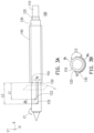
FIG. 3A is a schematic view of the bipolar electrode probe according to an embodiment of the disclosure.FIG. 3A shows the longitudinal direction x, the transverse direction y, and a direction z perpendicular to the longitudinal direction x and the transverse direction y.FIG. 3B is a schematic cross-sectional view taken along the plane I ofFIG. 3A . Referring toFIG. 1 andFIG. 3A , the area of thefirst opening 122 is smaller than the area of thesecond opening 132, such that a portion of theinsulation layer 120 is exposed by thesecond opening 132, and the exposed region of theinsulation layer 120 has a longitudinal insulation distance dx and a transverse insulation distance dy. - Referring to
FIG. 2 ,FIG. 3A, and FIG. 3B , in an embodiment, in the region of the transverse electric field E2, the longitudinal insulation distance dx is from a front end of thesecond opening 132 to a front end of thefirst opening 122 along the longitudinal direction x. The transverse insulation distance dy is from one end of thesecond opening 132 to one end of thefirst opening 122 on the same side along the transverse direction y. The longitudinal insulation distance dx is to ensure the longitudinal isolation distance between theconductive needle 110 and theconductive sleeve 130, so as to prevent a large current from flowing through the tissue due to a short isolation distance. If the isolation distance between theconductive needle 110 and theconductive sleeve 130 is too short, a large current may flow through the tissue to cause the temperature to rise too quickly and result in coking in a short time, and the ablation range will be only about 0.5mm of the probe surface. Such a small ablation range is inadequate for clinical use. - In addition, as shown in
FIG. 3B , the transverse insulation distance dy ensures the transverse isolation distance between theconductive needle 110 and theconductive sleeve 130, so as to maintain a current path that is sufficient for generating the transverse electric field E2 and prevent reduction of the ablation range due to a short current path. - Referring to
FIG. 3A and FIG. 3B , in an embodiment, in the region of the transverse electric field E2, a ratio of the area of theconductive needle 110 exposed by thefirst opening 122 to the area of theconductive sleeve 130 in the region outside thesecond opening 132 is 1:0.9 to 1:1.1. - Referring to
FIG. 3A and FIG. 3B , in the region of the transverse electric field E2, the area of theconductive needle 110 is L1×W1, wherein L1 is a length of theconductive needle 110 along the longitudinal direction x and W1 is a length of theconductive needle 110 in a circumferential direction; moreover, the area of theconductive sleeve 130 is L2×W2, wherein L2 is a length of theconductive sleeve 130 along the longitudinal direction x and W2 is a length of theconductive sleeve 130 in the circumferential direction. In an embodiment, the area of theconductive needle 110 may be equal to the area of theconductive sleeve 130, so as to generate the transverse electric field E2 uniformly. In other embodiments, when the ratio of the area of theconductive needle 110 to the area of theconductive sleeve 130 in the region of the transverse electric field E2 is set to 1:0.9 to 1:1.1, the transverse electric field E2 may be generated uniformly. - In addition, referring to
FIG. 3A and FIG. 3B , in an embodiment, a ratio of the area of a conductive region where the longitudinal electric field E1 exists to the area of a conductive region where the transverse electric field E2 exists is 1:2.1 to 1:2.6. Thereby, the front ablation region (the longitudinal electric field E1) and the rear ablation region (the transverse electric field E2) of thebipolar electrode probe 100 may be set to a proper ratio. - Further, referring to
FIG. 3A and FIG. 3B , in the region of the transverse electric field E2, the longitudinal insulation distance dx and the transverse insulation distance dy define an insulation area, and the area of theconductive needle 110 exposed by thefirst opening 122 and the area of theconductive sleeve 130 outside thesecond opening 132 define a conductive area, and a ratio of the insulation area to the conductive area is 1:8 to 1:44. - As shown in
FIG. 3A and FIG. 3B , in the region of the transverse electric field E2, the insulation area is the area of theinsulation layer 120 that exists in the region of the longitudinal insulation distance dx and the transverse insulation distance dy. In the region of the transverse electric field E2, the conductive area is a sum of the area L1×W1 of theconductive needle 110 and the area L2×W2 of theconductive sleeve 130. Through calculation, it is obtained that the ratio of the insulation area to the conductive area is 1:8 to 1:44. With this setting, the transverse electric field E2 is generated uniformly, so as to perform uniform ablation. -
FIG. 4A and FIG. 4B are schematic views showing that the insulation sleeve moves back and forth along the longitudinal direction according to another embodiment of the disclosure. Referring toFIG. 4A and FIG. 4B , relative to theconductive needle 110, theinsulation layer 120, and theconductive sleeve 130 disposed at fixed locations, theinsulation sleeve 140 is configured to be movable back and forth along the longitudinal direction x. As shown inFIG. 4A and FIG. 4B , when theinsulation sleeve 140 moves toward the front end of thebipolar electrode probe 100, the larger transverse electric field E2 changes to a smaller transverse electric field E2'. - In other words, the range of the transverse electric field E2 (ablation region) may be adjusted by moving the
insulation sleeve 140 back and forth along the longitudinal direction x. When ablating a superficial tissue of the epidermis, theinsulation sleeve 140 may be moved to completely close the transverse electric field E2 and to only use the longitudinal electric field E1 for ablation, so as to prevent burning the epidermis of the patient. In addition, when theinsulation sleeve 140 is moved toward the front end of thebipolar electrode probe 100, the range of the transverse electric field E2 is reduced to achieve a smaller ablation region; on the other hand, when theinsulation sleeve 140 is moved toward the rear end of thebipolar electrode probe 100, the range of the transverse electric field E2 is increased to achieve a larger ablation region. - In the disclosure, even if the
insulation sleeve 140 moves back and forth in the longitudinal direction x, the strength of the transverse electric field E2 in the transverse direction y remains uniform. Therefore, the ablation region is maintained uniform in the transverse direction y. - In the embodiments of
FIG. 1 to FIG. 4B , the number of thefirst openings 122 may be equal to the number of thesecond openings 132. The number of thefirst openings 122 is one or more, and the number of thesecond openings 132 is one or more. Thereby, an electrode pair is formed (as shown inFIG. 3B ). In other embodiments, however, the number of thefirst openings 122 and the number of thesecond openings 132 may be two, three, four, five, six, and so on, respectively. -
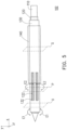
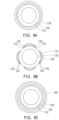
FIG. 5 is a schematic view of the bipolar electrode probe according to another embodiment of the disclosure.FIG. 6A is a schematic cross-sectional view taken along the plane O ofFIG. 5 .FIG. 6B is a schematic cross-sectional view taken along the plane P ofFIG. 5 .FIG. 6C is a schematic cross-sectional view taken along the plane Q ofFIG. 5 . In abipolar electrode probe 102, identical components are represented by identical reference numerals as shown inFIG. 1 to FIG. 4B , and therefore detailed descriptions thereof are not repeated hereinafter. Referring toFIG. 5 andFIG. 6B , in this embodiment, the number of thefirst openings 122 is four and the number of thesecond openings 132 is four, so as to form four electrode pairs (as shown inFIG. 6B ). -
FIG. 7 is a partially enlarged view of the bipolar electrode probe ofFIG. 5 . Referring toFIG. 7 , similarly, in thebipolar electrode probe 102, the region exposed by theinsulation layer 120 has the longitudinal insulation distance dx and the transverse insulation distance dy. The longitudinal insulation distance dx is to ensure the longitudinal isolation distance between theconductive needle 110 and theconductive sleeve 130 in the longitudinal direction, so as to prevent a large current from flowing through the tissue due to a short isolation distance. In addition, the transverse insulation distance dy is maintained to ensure the transverse isolation distance between theconductive needle 110 and theconductive sleeve 130, so as to maintain a current path that is sufficient for generating the transverse electric field E2 and prevent reduction of the ablation range due to a short current path. -
FIG. 8 is a partially enlarged view of the bipolar electrode probe ofFIG. 5 . Similar to the description ofFIG. 3B , as shown inFIG. 8 , in the region of the transverse electric field E2, the area of theconductive needle 110 may be equal to the area of theconductive sleeve 130, so as to generate the transverse electric field E2 uniformly. In another embodiment, when the ratio of the area of theconductive needle 110 to the area of theconductive sleeve 130 is set to 1:0.9 to 1:1.1, the transverse electric field E2 may be generated uniformly. -
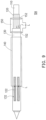
FIG. 9 is a schematic view of the bipolar electrode probe according to another embodiment of the disclosure. Components identical to those in the above embodiments ofFIG. 1 to FIG. 8 are represented by identical reference numerals, and therefore detailed descriptions thereof are not repeated hereinafter. Referring toFIG. 9 , abipolar electrode probe 104 of this embodiment may further include: aninfusion member 150 disposed at the rear ends of theinsulation layer 120 and theconductive sleeve 130. Theinfusion member 150 is disposed to allow a liquid substance L to pass through a gap between theinsulation layer 120 and theconductive sleeve 130 to be outputted from thefirst opening 122 and thesecond opening 132. - Referring to
FIG. 9 , the liquid substance L enters the gap between theinsulation layer 120 and theconductive sleeve 130 in the direction indicated by the arrow and flows out from thefirst opening 122 and thesecond opening 132 at the front to be infused into the target tissue. In an embodiment, the liquid substance L may be: an anesthetic drug for easing pain in the ablation region or physiological saline for increasing the volume of ablation. When thebipolar electrode probe 104 is used for ablation on an air-related organ (e.g., lungs), infusion of physiological saline facilitates the ablation and solves the problem of poor ablation effect resulting from that gas cannot effectively transfer current and heat. - The
infusion member 150 may further include sealingmembers 152 disposed at a junction between theinfusion member 150 and theinsulation layer 120 and a junction between theinfusion member 150 and theconductive sleeve 130, so as to properly assemble theinfusion member 150 to thebipolar electrode probe 104 and enable the liquid substance L to be properly inputted into the inlet of theinfusion member 150, and then through the gap between theinsulation layer 120 and theconductive sleeve 130, to be outputted to the target tissue from thefirst opening 122 and thesecond opening 132. - As shown in
FIG. 9 , theinfusion member 150 is assembled to thebipolar electrode probe 104 that has fourfirst openings 122 and foursecond openings 132; however, theinfusion member 150 may also be assembled to thebipolar electrode probe 100 that has onefirst opening 122 and onesecond opening 132, as shown inFIG. 3A . -
FIG. 10 is a table of comparison between the bipolar electrode probe ofFIG. 1 to FIG. 4B and the conventional unipolar electrode probe used for ablating the target tissue. Referring toFIG. 10 , when a target length for ablation of the target tissue is 5mm, it is known that the unipolar electrode probe forms an ablation region of 6mm in the longitudinal direction and an ablation region of 4mm in the transverse direction; on the other hand, thebipolar electrode probe 100 according to the embodiments of the disclosure forms an ablation region of 6mm in the longitudinal direction and an ablation region of 3.5mm in the transverse direction, which at least achieves an ablation effect similar to the unipolar electrode probe. - Referring to
FIG. 10 again, when the target length for ablation of the target tissue is 7mm, it is known that the unipolar electrode probe forms an ablation region of 9mm in the longitudinal direction and an ablation region of 4mm in the transverse direction; on the other hand, thebipolar electrode probe 100 according to the embodiments of the disclosure forms an ablation region of 6mm in the longitudinal direction and an ablation region of 4mm in the transverse direction, which at least achieves an ablation effect similar to the unipolar electrode probe. It is known from the above that the length of the ablation region formed by the unipolar electrode probe in the longitudinal direction is 9mm, which exceeds the target length 7mm and the operation accuracy drops. However, the length of the ablation region formed by thebipolar electrode probe 100 of the disclosure in the longitudinal direction is 6mm, which is close to the target length 7mm and achieves favorable operation accuracy. - Referring to
FIG. 10 again, when the target length for ablation of the target tissue is 10mm, it is known that the unipolar electrode probe forms an ablation region of 11mm in the longitudinal direction and an ablation region of 4mm in the transverse direction; on the other hand, thebipolar electrode probe 100 according to the embodiments of the disclosure forms an ablation region of 11mm in the longitudinal direction and an ablation region of 4.5mm in the transverse direction, which at least achieves an ablation effect similar to the unipolar electrode probe. - To sum up, the bipolar electrode probe of the disclosure at least achieves the following. First, the active electrode and the passive electrode are formed on the same needle without use of the conventional additional electrode plate, which prevents an unnecessary current from flowing through the normal organs and improves the safety for patients. Second, the ablation region is formed uniformly, which avoids generating a hot spot and prevents burning the patient's epidermis when ablating a superficial tissue of the epidermis. Third, the bipolar electrode probe has a sleeve-type structure design, which simplifies the overall assembly and avoids weakening the mechanical strength. Furthermore, when the insulation sleeve is configured movable, the insulation sleeve may be moved back and forth along the longitudinal direction, which makes it easy to adjust the range of the transverse electric field (the ablation region) for ablating target tissues of different sizes (e.g., cancer cells) in one operation. Because of the structure design of the disclosure, the transverse electric field has a uniform strength, and when the insulation sleeve is moved along the longitudinal direction to obtain different lengths of conductivity, the target tissue is uniformly heated around the transverse electric field. In addition, when the infusion member is used, the bipolar electrode probe has a channel for injecting liquid substances (e.g., anesthetic) for easing the patient's pain during treatment.
Claims (8)
- A bipolar electrode probe (100, 102, 104), comprising:a conductive needle (110) having a longitudinal direction (x) and a transverse direction (y) perpendicular to the longitudinal direction (x);an insulation layer (120) covering the conductive needle (110) and having at least a first opening (122);a conductive sleeve (130) covering the insulation layer (120) and having at least one second opening (132); andan insulation sleeve (140) covering the conductive sleeve (130), wherein the insulation sleeve (140) is configured to be movable back and forth along the longitudinal direction (x),wherein a needle end portion of the conductive needle (110) is exposed from distal ends of the insulation layer (120), the conductive sleeve (130) and the insulation sleeve (140),wherein when the bipolar electrode probe (100, 102, 104) is applied with power and a voltage is applied between the conductive needle (110) and the conductive sleeve (130) at a rear end of the bipolar electrode probe (100, 102, 104), a longitudinal electric field (E1) is formed from a front end of the conductive needle (110) to the conductive sleeve (130) along the longitudinal direction (x), anda transverse electric field (E2, E2') is formed from the conductive needle (110) to the conductive sleeve (130) via the at least one first opening (122) and the at least one second opening (132) along the transverse direction (y);wherein the bipolar electrode probe (100, 102, 104) has: a front ablation region, where the longitudinal electric field (E1) is formed, and a rear ablation region, where the transverse electric field (E2, E2') is formed;wherein a tip of the insulation layer (120) is protruding distally from the conductive sleeve (130);wherein the conductive sleeve (130) is protruding distally from the insulation sleeve (140);whereinin a region of the transverse electric field (E2, E2'), a longitudinal insulation distance (dx) exists between a front end of the at least one second opening (132) and a front end of the at least one first opening (122) along the longitudinal direction (x); anda transverse insulation distance (dy) exists between an end of the at least one second opening (132) and an end of the at least one first opening (122) on a same side along the transverse direction (y).
- The bipolar electrode probe (100, 102, 104) according to claim 1, wherein
an area of the at least one first opening (122) is smaller than an area of the at least one second opening (132). - The bipolar electrode probe (100, 102, 104) according to any one of claims 1 or 2, wherein
in a region of the transverse electric field (E2, E2'), a ratio of an area (W1×L1) of the conductive needle (110) exposed by the at least one first opening (122) to an area (W2×L2) of the conductive sleeve (130) in a region outside the at least one second opening (132) is 1:0.9 to 1:1.1. - The bipolar electrode probe (100, 102, 104) according to any one of claims 1 to 3, whereina ratio of a first area of a conductive region where the longitudinal electric field (E1) exists to a second area of a conductive region where the transverse electric field (E2, E2') exists is 1:2.1 to 1:2.6,wherein the first area of the conductive region of the conductive needle (110) is defined from a tip of the conductive needle (110) to a front side of the at least one second opening (132) along the longitudinal direction,wherein the second area of the conductive region of the conductive needle (110) is defined a sum of a region of the conductive needle (110) exposed by the at least first opening (122) and a region of the conductive sleeve (130) outside the at least one second opening (132) and exposed by the insulation sleeve (140) and other than the first area.
- The bipolar electrode probe (100, 102, 104) according to any one of claims 1 to 4, whereinin a region of the transverse electric field (E2, E2'), a longitudinal insulation distance (dx) exists between a front end of the at least one second opening (132) and a front end of the at least one first opening (122) along the longitudinal direction (x); anda transverse insulation distance (dy) exists between an end of the at least one second opening (132) and an end of the at least one first opening (122) on a same side along the transverse direction (y),wherein in the region of the transverse electric field (E2, E2'), the longitudinal insulation distance (dx) and the transverse insulation distance (dy) define an insulation area, and an area (W1×L1) of the conductive needle (110) exposed by the at least one first opening (122) and an area (W2×L2) of the conductive sleeve (130) outside the at least one second opening (132) define a conductive area, anda ratio of the insulation area to the conductive area is 1:8 to 1:44.
- The bipolar electrode probe (100, 102, 104) according to any one of claims 1 to 5, wherein
the number of the at least one first opening (122) is equal to the number of the at least one second opening (132). - The bipolar electrode probe (100, 102, 104) according to any one of claims 1 to 6, further comprising:an infusion member (150) disposed at rear ends of the insulation layer (120) and the conductive sleeve (130),wherein the infusion member (150) is configured to allow a liquid substance (L) to pass through a gap between the insulation layer (120) and the conductive sleeve (130) to be outputted from the at least one first opening (122) and the at least one second opening (132).
- The bipolar electrode probe (100, 102, 104) according to claim 7, wherein
the infusion member (150) further comprises a plurality of sealing members (152) disposed at a junction between the infusion member (150) and the insulation layer (120) and at a junction between the infusion member (150) and the conductive sleeve (130).
Applications Claiming Priority (1)
| Application Number | Priority Date | Filing Date | Title |
|---|---|---|---|
| TW106145210A TWI634868B (en) | 2017-12-22 | 2017-12-22 | Bipolar electrode probe |
Publications (2)
| Publication Number | Publication Date |
|---|---|
| EP3501440A1 EP3501440A1 (en) | 2019-06-26 |
| EP3501440B1 true EP3501440B1 (en) | 2025-07-09 |
Family
ID=61868281
Family Applications (1)
| Application Number | Title | Priority Date | Filing Date |
|---|---|---|---|
| EP18165102.7A Active EP3501440B1 (en) | 2017-12-22 | 2018-03-29 | Bipolar electrode probe |
Country Status (5)
| Country | Link |
|---|---|
| US (1) | US10898261B2 (en) |
| EP (1) | EP3501440B1 (en) |
| JP (1) | JP6535121B1 (en) |
| CN (1) | CN109953821B (en) |
| TW (1) | TWI634868B (en) |
Families Citing this family (10)
| Publication number | Priority date | Publication date | Assignee | Title |
|---|---|---|---|---|
| CN112641506B (en) * | 2019-10-11 | 2025-01-17 | 广州爱锘德医疗器械有限公司 | Slide fastener structure and adjusting device |
| CN111529049B (en) * | 2019-10-11 | 2025-12-19 | 深圳钮迈科技有限公司 | Double-electrode probe and operation method thereof |
| US12070243B2 (en) | 2020-09-25 | 2024-08-27 | Industrial Technology Research Institute | Medical material needle |
| US20240206937A1 (en) * | 2021-05-22 | 2024-06-27 | Snipe Medical Ltd | Tumor ablation tools and techniques |
| CN113693714B (en) * | 2021-10-29 | 2022-02-22 | 北京微刀医疗科技有限公司 | Water-cooling internal circulation type bipolar ablation needle for electroporation and focus ablation device |
| CN114557766B (en) * | 2022-01-17 | 2023-07-28 | 安隽医疗科技(南京)有限公司 | A length-adjustable radiofrequency ablation needle system |
| CN116725656B (en) * | 2022-03-03 | 2026-03-06 | 上海微创电生理医疗科技股份有限公司 | A medical catheter and ablation system |
| CN115399865A (en) * | 2022-11-02 | 2022-11-29 | 杭州维纳安可医疗科技有限责任公司 | Ablation electrode needle, ablation system and machining process of ablation electrode needle |
| CN115399869A (en) * | 2022-11-02 | 2022-11-29 | 杭州维纳安可医疗科技有限责任公司 | Ablation needle, processing technology, ablation system and using method thereof |
| CN116269724A (en) * | 2023-02-08 | 2023-06-23 | 南京航空航天大学 | A steam ablation needle for directional ablation |
Family Cites Families (26)
| Publication number | Priority date | Publication date | Assignee | Title |
|---|---|---|---|---|
| US6530922B2 (en) | 1993-12-15 | 2003-03-11 | Sherwood Services Ag | Cluster ablation electrode system |
| US6106524A (en) | 1995-03-03 | 2000-08-22 | Neothermia Corporation | Methods and apparatus for therapeutic cauterization of predetermined volumes of biological tissue |
| US6312428B1 (en) | 1995-03-03 | 2001-11-06 | Neothermia Corporation | Methods and apparatus for therapeutic cauterization of predetermined volumes of biological tissue |
| US6638277B2 (en) | 2000-07-06 | 2003-10-28 | Scimed Life Systems, Inc. | Tumor ablation needle with independently activated and independently traversing tines |
| US7744595B2 (en) * | 2000-08-01 | 2010-06-29 | Arqos Surgical, Inc. | Voltage threshold ablation apparatus |
| US7387628B1 (en) | 2000-09-15 | 2008-06-17 | Boston Scientific Scimed, Inc. | Methods and systems for focused bipolar tissue ablation |
| US7258690B2 (en) | 2003-03-28 | 2007-08-21 | Relievant Medsystems, Inc. | Windowed thermal ablation probe |
| US7416549B2 (en) | 2003-10-10 | 2008-08-26 | Boston Scientific Scimed, Inc. | Multi-zone bipolar ablation probe assembly |
| US20050288663A1 (en) | 2004-06-28 | 2005-12-29 | Kamran Behzadian | Method and apparatus for substantial uniform ablation about a bipolar array of electrodes |
| JP5046931B2 (en) * | 2004-08-05 | 2012-10-10 | タイコ ヘルスケア グループ リミテッド パートナーシップ | Method and apparatus for coagulating and / or constricting hollow anatomical structures |
| US7976542B1 (en) | 2006-03-02 | 2011-07-12 | Cosman Eric R | Adjustable high frequency electrode |
| US8216226B2 (en) | 2007-04-13 | 2012-07-10 | Boston Scientific Scimed, Inc. | Radiofrequency ablation device |
| DE102007042524A1 (en) | 2007-09-07 | 2009-03-12 | Celon Ag Medical Instruments | Coagulation template and application device |
| EP2366352B1 (en) | 2010-03-19 | 2013-07-31 | Vesalius Medical Technologies Bvba | Device for radio frequency ablation (RFA) |
| JP5763263B2 (en) * | 2011-04-08 | 2015-08-12 | コビディエン エルピー | Flexible microwave catheter for natural or artificial lumens |
| KR20120126706A (en) | 2011-05-12 | 2012-11-21 | (주) 태웅메디칼 | Asymmetric bipolar electrode needle for high frequency thermotherapy |
| US9078665B2 (en) | 2011-09-28 | 2015-07-14 | Angiodynamics, Inc. | Multiple treatment zone ablation probe |
| KR101415900B1 (en) | 2012-05-18 | 2014-07-08 | 신경민 | Reiterating type bipolar electrode for high frequency thermotherapy |
| US20150045675A1 (en) * | 2012-06-01 | 2015-02-12 | Ary Chernomorsky | Percutaneous methods and devices for carotid body ablation |
| CN102860870B (en) * | 2012-08-14 | 2016-09-07 | 中美联合技术(北京)有限公司 | A kind of bipolar operation electrode device |
| TWM464141U (en) | 2013-06-17 | 2013-11-01 | Jiaxin Biotech Co Ltd | Inner core for bipolar ablation device |
| US10314647B2 (en) * | 2013-12-23 | 2019-06-11 | Medtronic Advanced Energy Llc | Electrosurgical cutting instrument |
| CN104688333A (en) | 2014-12-17 | 2015-06-10 | 珠海和佳医疗设备股份有限公司 | Single-needle bipolar radiofrequency ablation electrode needle and radio-frequency electrode bare area adjusting method thereof |
| KR20180006365A (en) | 2015-01-21 | 2018-01-17 | 서린 메디컬 인코포레이티드 | Systems and devices for identifying and limiting nerve conduction |
| US9119628B1 (en) | 2015-01-21 | 2015-09-01 | Serene Medical, Inc. | Systems and devices to identify and limit nerve conduction |
| JP6723249B2 (en) * | 2015-01-30 | 2020-07-15 | アールエフイーエムビー ホールディングス リミテッド ライアビリティ カンパニー | System and method for ablating soft tissue |
-
2017
- 2017-12-22 TW TW106145210A patent/TWI634868B/en active
- 2017-12-25 US US15/853,856 patent/US10898261B2/en active Active
-
2018
- 2018-02-06 CN CN201810116047.2A patent/CN109953821B/en active Active
- 2018-03-29 EP EP18165102.7A patent/EP3501440B1/en active Active
- 2018-04-17 JP JP2018079159A patent/JP6535121B1/en active Active
Also Published As
| Publication number | Publication date |
|---|---|
| EP3501440A1 (en) | 2019-06-26 |
| JP2019111311A (en) | 2019-07-11 |
| TW201927253A (en) | 2019-07-16 |
| CN109953821B (en) | 2021-03-26 |
| CN109953821A (en) | 2019-07-02 |
| US10898261B2 (en) | 2021-01-26 |
| TWI634868B (en) | 2018-09-11 |
| US20190192216A1 (en) | 2019-06-27 |
| JP6535121B1 (en) | 2019-06-26 |
Similar Documents
| Publication | Publication Date | Title |
|---|---|---|
| US10898261B2 (en) | Bipolar electrode probe | |
| Gerhard | Surgical Electrotechnology: Quo Vadis? | |
| JP4138249B2 (en) | High frequency energy emitting device | |
| RU2499574C2 (en) | Bipolar radio-frequency ablative instrument | |
| RU2612863C2 (en) | Electrosurgical device with offset conducting element | |
| US20040193152A1 (en) | Windowed thermal ablation probe | |
| WO2005089663A1 (en) | Saline-enhanced catheter for radiofrequency tumor ablation | |
| JP2004267759A (en) | Method to cure bone containing intraosseous nerve ion, method to cure corpus vertebra containing nerve bvn of corpus vertebra, device to denervate intraosseous nerve, method to cure healthy corpus vertebra, system to denervate intraosseous nerve, and method to cure corpus vertebra and its bvn | |
| US9814519B2 (en) | Ablation probe with ribbed insulated sheath | |
| KR101522662B1 (en) | An electrode device for a high frequency treatment | |
| US20220313353A1 (en) | Ent instrument with rf electrodes on wire frame | |
| US20250009404A1 (en) | Multi-electrode devices, systems, and methods for medical procedures | |
| US20170360501A1 (en) | Disposable bipolar coaxial radio frequency ablation needle, system and method | |
| US20200000516A1 (en) | Sterile disposable bipolar ablation needle, associated system, and method of use | |
| US20150196350A1 (en) | Electrosurgical devices having enhanced effectiveness and methods of making and using same | |
| Smith et al. | Radiofrequency electrosurgery | |
| RU2368406C2 (en) | Method and device for destroying malignant tumours | |
| US20240252227A1 (en) | Electrode device comprising high-frequency electrode and multi-functional electrode | |
| US20220233832A1 (en) | Cryotherapy Systems and Methods | |
| US20180071008A1 (en) | Instruments and methods for thermal tissue treatment | |
| CN105792765A (en) | Apparatus for creating linear lesions in body tissue within a body vessel | |
| EP3897436B1 (en) | Steerable tip cooled radiofrequency ablation probe | |
| RU2740699C2 (en) | Sterile disposable bipolar ablation needle, associated system, and method of use | |
| KR20260017470A (en) | Devices, systems and methods for preventing arcing between electrodes during medical procedures | |
| WO2020153976A1 (en) | Sterile disposable bipolar ablation needle, associated system, and method of use |
Legal Events
| Date | Code | Title | Description |
|---|---|---|---|
| PUAI | Public reference made under article 153(3) epc to a published international application that has entered the european phase |
Free format text: ORIGINAL CODE: 0009012 |
|
| STAA | Information on the status of an ep patent application or granted ep patent |
Free format text: STATUS: REQUEST FOR EXAMINATION WAS MADE |
|
| 17P | Request for examination filed |
Effective date: 20180329 |
|
| AK | Designated contracting states |
Kind code of ref document: A1 Designated state(s): AL AT BE BG CH CY CZ DE DK EE ES FI FR GB GR HR HU IE IS IT LI LT LU LV MC MK MT NL NO PL PT RO RS SE SI SK SM TR |
|
| AX | Request for extension of the european patent |
Extension state: BA ME |
|
| STAA | Information on the status of an ep patent application or granted ep patent |
Free format text: STATUS: EXAMINATION IS IN PROGRESS |
|
| 17Q | First examination report despatched |
Effective date: 20220615 |
|
| GRAP | Despatch of communication of intention to grant a patent |
Free format text: ORIGINAL CODE: EPIDOSNIGR1 |
|
| STAA | Information on the status of an ep patent application or granted ep patent |
Free format text: STATUS: GRANT OF PATENT IS INTENDED |
|
| INTG | Intention to grant announced |
Effective date: 20250204 |
|
| GRAS | Grant fee paid |
Free format text: ORIGINAL CODE: EPIDOSNIGR3 |
|
| GRAA | (expected) grant |
Free format text: ORIGINAL CODE: 0009210 |
|
| STAA | Information on the status of an ep patent application or granted ep patent |
Free format text: STATUS: THE PATENT HAS BEEN GRANTED |
|
| AK | Designated contracting states |
Kind code of ref document: B1 Designated state(s): AL AT BE BG CH CY CZ DE DK EE ES FI FR GB GR HR HU IE IS IT LI LT LU LV MC MK MT NL NO PL PT RO RS SE SI SK SM TR |
|
| REG | Reference to a national code |
Ref country code: GB Ref legal event code: FG4D |
|
| REG | Reference to a national code |
Ref country code: CH Ref legal event code: EP |
|
| P01 | Opt-out of the competence of the unified patent court (upc) registered |
Free format text: CASE NUMBER: APP_26675/2025 Effective date: 20250604 |
|
| REG | Reference to a national code |
Ref country code: IE Ref legal event code: FG4D |
|
| REG | Reference to a national code |
Ref country code: DE Ref legal event code: R096 Ref document number: 602018083363 Country of ref document: DE |
|
| REG | Reference to a national code |
Ref country code: NL Ref legal event code: MP Effective date: 20250709 |
|
| PG25 | Lapsed in a contracting state [announced via postgrant information from national office to epo] |
Ref country code: PT Free format text: LAPSE BECAUSE OF FAILURE TO SUBMIT A TRANSLATION OF THE DESCRIPTION OR TO PAY THE FEE WITHIN THE PRESCRIBED TIME-LIMIT Effective date: 20251110 |
|
| PG25 | Lapsed in a contracting state [announced via postgrant information from national office to epo] |
Ref country code: NL Free format text: LAPSE BECAUSE OF FAILURE TO SUBMIT A TRANSLATION OF THE DESCRIPTION OR TO PAY THE FEE WITHIN THE PRESCRIBED TIME-LIMIT Effective date: 20250709 |
|
| REG | Reference to a national code |
Ref country code: AT Ref legal event code: MK05 Ref document number: 1811082 Country of ref document: AT Kind code of ref document: T Effective date: 20250709 |
|
| PG25 | Lapsed in a contracting state [announced via postgrant information from national office to epo] |
Ref country code: IS Free format text: LAPSE BECAUSE OF FAILURE TO SUBMIT A TRANSLATION OF THE DESCRIPTION OR TO PAY THE FEE WITHIN THE PRESCRIBED TIME-LIMIT Effective date: 20251109 |
|
| PG25 | Lapsed in a contracting state [announced via postgrant information from national office to epo] |
Ref country code: NO Free format text: LAPSE BECAUSE OF FAILURE TO SUBMIT A TRANSLATION OF THE DESCRIPTION OR TO PAY THE FEE WITHIN THE PRESCRIBED TIME-LIMIT Effective date: 20251009 |
|
| REG | Reference to a national code |
Ref country code: LT Ref legal event code: MG9D |
|
| PG25 | Lapsed in a contracting state [announced via postgrant information from national office to epo] |
Ref country code: AT Free format text: LAPSE BECAUSE OF FAILURE TO SUBMIT A TRANSLATION OF THE DESCRIPTION OR TO PAY THE FEE WITHIN THE PRESCRIBED TIME-LIMIT Effective date: 20250709 |
|
| PG25 | Lapsed in a contracting state [announced via postgrant information from national office to epo] |
Ref country code: FI Free format text: LAPSE BECAUSE OF FAILURE TO SUBMIT A TRANSLATION OF THE DESCRIPTION OR TO PAY THE FEE WITHIN THE PRESCRIBED TIME-LIMIT Effective date: 20250709 |
|
| PG25 | Lapsed in a contracting state [announced via postgrant information from national office to epo] |
Ref country code: HR Free format text: LAPSE BECAUSE OF FAILURE TO SUBMIT A TRANSLATION OF THE DESCRIPTION OR TO PAY THE FEE WITHIN THE PRESCRIBED TIME-LIMIT Effective date: 20250709 |
|
| PG25 | Lapsed in a contracting state [announced via postgrant information from national office to epo] |
Ref country code: GR Free format text: LAPSE BECAUSE OF FAILURE TO SUBMIT A TRANSLATION OF THE DESCRIPTION OR TO PAY THE FEE WITHIN THE PRESCRIBED TIME-LIMIT Effective date: 20251010 |
|
| PG25 | Lapsed in a contracting state [announced via postgrant information from national office to epo] |
Ref country code: SE Free format text: LAPSE BECAUSE OF FAILURE TO SUBMIT A TRANSLATION OF THE DESCRIPTION OR TO PAY THE FEE WITHIN THE PRESCRIBED TIME-LIMIT Effective date: 20250709 |
|
| PG25 | Lapsed in a contracting state [announced via postgrant information from national office to epo] |
Ref country code: LV Free format text: LAPSE BECAUSE OF FAILURE TO SUBMIT A TRANSLATION OF THE DESCRIPTION OR TO PAY THE FEE WITHIN THE PRESCRIBED TIME-LIMIT Effective date: 20250709 |
|
| PG25 | Lapsed in a contracting state [announced via postgrant information from national office to epo] |
Ref country code: BG Free format text: LAPSE BECAUSE OF FAILURE TO SUBMIT A TRANSLATION OF THE DESCRIPTION OR TO PAY THE FEE WITHIN THE PRESCRIBED TIME-LIMIT Effective date: 20250709 Ref country code: PL Free format text: LAPSE BECAUSE OF FAILURE TO SUBMIT A TRANSLATION OF THE DESCRIPTION OR TO PAY THE FEE WITHIN THE PRESCRIBED TIME-LIMIT Effective date: 20250709 |
|
| PG25 | Lapsed in a contracting state [announced via postgrant information from national office to epo] |
Ref country code: RS Free format text: LAPSE BECAUSE OF FAILURE TO SUBMIT A TRANSLATION OF THE DESCRIPTION OR TO PAY THE FEE WITHIN THE PRESCRIBED TIME-LIMIT Effective date: 20251009 |
|
| PG25 | Lapsed in a contracting state [announced via postgrant information from national office to epo] |
Ref country code: ES Free format text: LAPSE BECAUSE OF FAILURE TO SUBMIT A TRANSLATION OF THE DESCRIPTION OR TO PAY THE FEE WITHIN THE PRESCRIBED TIME-LIMIT Effective date: 20250709 |
|
| PG25 | Lapsed in a contracting state [announced via postgrant information from national office to epo] |
Ref country code: SM Free format text: LAPSE BECAUSE OF FAILURE TO SUBMIT A TRANSLATION OF THE DESCRIPTION OR TO PAY THE FEE WITHIN THE PRESCRIBED TIME-LIMIT Effective date: 20250709 |
|
| PGFP | Annual fee paid to national office [announced via postgrant information from national office to epo] |
Ref country code: GB Payment date: 20260327 Year of fee payment: 9 |
|
| PG25 | Lapsed in a contracting state [announced via postgrant information from national office to epo] |
Ref country code: DK Free format text: LAPSE BECAUSE OF FAILURE TO SUBMIT A TRANSLATION OF THE DESCRIPTION OR TO PAY THE FEE WITHIN THE PRESCRIBED TIME-LIMIT Effective date: 20250709 |
|
| PGFP | Annual fee paid to national office [announced via postgrant information from national office to epo] |
Ref country code: DE Payment date: 20260327 Year of fee payment: 9 |
|
| PG25 | Lapsed in a contracting state [announced via postgrant information from national office to epo] |
Ref country code: IT Free format text: LAPSE BECAUSE OF FAILURE TO SUBMIT A TRANSLATION OF THE DESCRIPTION OR TO PAY THE FEE WITHIN THE PRESCRIBED TIME-LIMIT Effective date: 20250709 |
|
| PGFP | Annual fee paid to national office [announced via postgrant information from national office to epo] |
Ref country code: FR Payment date: 20260325 Year of fee payment: 9 |
|
| PG25 | Lapsed in a contracting state [announced via postgrant information from national office to epo] |
Ref country code: CZ Free format text: LAPSE BECAUSE OF FAILURE TO SUBMIT A TRANSLATION OF THE DESCRIPTION OR TO PAY THE FEE WITHIN THE PRESCRIBED TIME-LIMIT Effective date: 20250709 |
|
| PG25 | Lapsed in a contracting state [announced via postgrant information from national office to epo] |
Ref country code: SK Free format text: LAPSE BECAUSE OF FAILURE TO SUBMIT A TRANSLATION OF THE DESCRIPTION OR TO PAY THE FEE WITHIN THE PRESCRIBED TIME-LIMIT Effective date: 20250709 Ref country code: EE Free format text: LAPSE BECAUSE OF FAILURE TO SUBMIT A TRANSLATION OF THE DESCRIPTION OR TO PAY THE FEE WITHIN THE PRESCRIBED TIME-LIMIT Effective date: 20250709 |
|
| PLBE | No opposition filed within time limit |
Free format text: ORIGINAL CODE: 0009261 |
|
| STAA | Information on the status of an ep patent application or granted ep patent |
Free format text: STATUS: NO OPPOSITION FILED WITHIN TIME LIMIT |