EP3501347A1 - Beverage dispenser with a plurality of dissolution chambers - Google Patents
Beverage dispenser with a plurality of dissolution chambers Download PDFInfo
- Publication number
- EP3501347A1 EP3501347A1 EP17210205.5A EP17210205A EP3501347A1 EP 3501347 A1 EP3501347 A1 EP 3501347A1 EP 17210205 A EP17210205 A EP 17210205A EP 3501347 A1 EP3501347 A1 EP 3501347A1
- Authority
- EP
- European Patent Office
- Prior art keywords
- sub
- frame
- chambers
- beverage
- chamber
- Prior art date
- Legal status (The legal status is an assumption and is not a legal conclusion. Google has not performed a legal analysis and makes no representation as to the accuracy of the status listed.)
- Withdrawn
Links
- 235000013361 beverage Nutrition 0.000 title claims abstract description 111
- 238000004090 dissolution Methods 0.000 title claims abstract description 44
- 239000003085 diluting agent Substances 0.000 claims abstract description 79
- 239000004615 ingredient Substances 0.000 claims abstract description 55
- 238000002360 preparation method Methods 0.000 claims abstract description 29
- 239000000463 material Substances 0.000 claims description 6
- 238000004140 cleaning Methods 0.000 description 21
- 239000000843 powder Substances 0.000 description 15
- 240000007154 Coffea arabica Species 0.000 description 13
- 235000016213 coffee Nutrition 0.000 description 13
- 235000013353 coffee beverage Nutrition 0.000 description 13
- 239000008267 milk Substances 0.000 description 12
- 235000013336 milk Nutrition 0.000 description 12
- 210000004080 milk Anatomy 0.000 description 12
- 235000008504 concentrate Nutrition 0.000 description 7
- 239000012141 concentrate Substances 0.000 description 5
- 239000007788 liquid Substances 0.000 description 5
- 244000269722 Thea sinensis Species 0.000 description 4
- 230000035622 drinking Effects 0.000 description 4
- 235000013616 tea Nutrition 0.000 description 4
- 235000019219 chocolate Nutrition 0.000 description 3
- 230000003670 easy-to-clean Effects 0.000 description 3
- 235000021539 instant coffee Nutrition 0.000 description 3
- 238000004519 manufacturing process Methods 0.000 description 3
- 230000005484 gravity Effects 0.000 description 2
- 238000007373 indentation Methods 0.000 description 2
- 238000012423 maintenance Methods 0.000 description 2
- 239000000203 mixture Substances 0.000 description 2
- XLYOFNOQVPJJNP-UHFFFAOYSA-N water Substances O XLYOFNOQVPJJNP-UHFFFAOYSA-N 0.000 description 2
- 241000894006 Bacteria Species 0.000 description 1
- 244000299461 Theobroma cacao Species 0.000 description 1
- 230000000712 assembly Effects 0.000 description 1
- 238000000429 assembly Methods 0.000 description 1
- 235000015123 black coffee Nutrition 0.000 description 1
- 235000015116 cappuccino Nutrition 0.000 description 1
- 230000003247 decreasing effect Effects 0.000 description 1
- YSXLJTGZMRNQSG-UHFFFAOYSA-L disodium;6-amino-5-[[2-[4-[2-[4-[2-[(2-amino-5-sulfonatonaphthalen-1-yl)diazenyl]phenyl]sulfonyloxyphenyl]propan-2-yl]phenoxy]sulfonylphenyl]diazenyl]naphthalene-1-sulfonate Chemical compound [Na+].[Na+].C1=CC=C2C(N=NC3=CC=CC=C3S(=O)(=O)OC3=CC=C(C=C3)C(C)(C=3C=CC(OS(=O)(=O)C=4C(=CC=CC=4)N=NC=4C5=CC=CC(=C5C=CC=4N)S([O-])(=O)=O)=CC=3)C)=C(N)C=CC2=C1S([O-])(=O)=O YSXLJTGZMRNQSG-UHFFFAOYSA-L 0.000 description 1
- 235000013399 edible fruits Nutrition 0.000 description 1
- 230000000694 effects Effects 0.000 description 1
- 239000004744 fabric Substances 0.000 description 1
- 239000012530 fluid Substances 0.000 description 1
- 235000012041 food component Nutrition 0.000 description 1
- 239000005417 food ingredient Substances 0.000 description 1
- 238000002347 injection Methods 0.000 description 1
- 239000007924 injection Substances 0.000 description 1
- 235000020344 instant tea Nutrition 0.000 description 1
- 238000012986 modification Methods 0.000 description 1
- 230000004048 modification Effects 0.000 description 1
- 230000002572 peristaltic effect Effects 0.000 description 1
- 235000014347 soups Nutrition 0.000 description 1
- 239000006188 syrup Substances 0.000 description 1
- 235000020357 syrup Nutrition 0.000 description 1
- 239000008399 tap water Substances 0.000 description 1
- 235000020679 tap water Nutrition 0.000 description 1
Images





Classifications
-
- A—HUMAN NECESSITIES
- A47—FURNITURE; DOMESTIC ARTICLES OR APPLIANCES; COFFEE MILLS; SPICE MILLS; SUCTION CLEANERS IN GENERAL
- A47J—KITCHEN EQUIPMENT; COFFEE MILLS; SPICE MILLS; APPARATUS FOR MAKING BEVERAGES
- A47J31/00—Apparatus for making beverages
- A47J31/40—Beverage-making apparatus with dispensing means for adding a measured quantity of ingredients, e.g. coffee, water, sugar, cocoa, milk, tea
- A47J31/401—Beverage-making apparatus with dispensing means for adding a measured quantity of ingredients, e.g. coffee, water, sugar, cocoa, milk, tea whereby the powder ingredients and the water are delivered to a mixing bowl
Definitions
- the present invention relates to beverage dispensers preparing beverages from a soluble beverage ingredient and in which a dose of said ingredient is mixed with a liquid in a mixing chamber.
- the biggest apparatus enable the preparation of different types of beverages depending on the selection made by the consumer.
- such apparatus enable alternatively the preparation of coffee, milk, chocolate or tea and mixtures of said beverages, usually mixtures of milk with coffee, chocolate or tea.
- the apparatus comprises several containers sorting separately different beverage ingredients such as coffee, tea, milk and chocolate soluble powders and several dissolution chambers dedicated to the preparation of the different beverages.
- the internal parts of the apparatus must be regularly cleaned in order to avoid the growth of bacteria due to residues of beverages in the machine and clogging. Cleaning operation usually concerns the following parts of the dispenser:
- a beverage preparation apparatus comprising a main frame supporting the functional components of the apparatus. A part of said components comprises :
- the beverage dispenser of the present invention comprises a main frame in which the different functional elements for preparing the beverages are positioned.
- the main frame supports the diluent supply system providing the diluent to prepare the beverages.
- the diluent can be any suitable liquid adapted for dissolving a soluble beverage ingredient.
- a preferred diluent is water either hot or cold.
- the diluent supply system of the apparatus comprises at least a diluent tank or diluent supply (such as tap water), a diluent pump, a diluent heater and/or cooler and valves for actuating the diluent delivery.
- the system can also comprise a selection valve for delivering diluent at either hot or cold temperature.
- the main frame supports at least two containers, said container being configured for storing soluble beverage ingredients.
- each container comprises a storing tank and an ingredient outlet.
- the outlet is positioned at the bottom of the tank.
- the apparatus comprises at least one soluble beverage ingredient dosing device, preferably one dosing device per container.
- the dosing device delivers the dosed ingredient to the dissolution chamber.
- the dosing device is preferably a rotatable volumetric dosing member.
- the devices for dosing can be comprised in the list of a dosing screw, a dosing auger or perforated discs.
- the dosing device can be integrated inside the container or provided at the outlet of the container.
- the dosing device is placed inside the container and positioned at the bottom of the container. It is preferably a spring or screw auger. Such augers displace a volume of powder from the container to the powder outlet.
- This sub-assembly composed of the container and the dosing device is usually identified as a canister in current beverage dispensers.
- the dosing device is preferably a peristaltic pump cooperating with a flexible tube filled with the concentrate.
- the main frame supports at least two dissolution chambers configured for preparing a beverage from a dose of soluble beverage ingredient and a dose of diluent.
- Each dissolution chamber comprises :
- the apparatus comprises a sub-frame.
- This sub-frame is supported by the main frame and is configured for holding all the dissolution chambers.
- the sub-frame is removably attached to the main frame. Accordingly, when the sub-frame is removed from the main frame of the apparatus, all the chambers are simultaneously removed from the apparatus. In one gesture, the operator removes all the chambers and gets a full and direct access to the internal parts of the apparatus hidden behind the chambers.
- the sub-frame is positioned in a receiving area of the main frame and this receiving area forms a cavity inside the apparatus.
- This cavity presents a front face and lateral faces, these lateral faces extending inside the apparatus back to said front face.
- the receiving area defines a volume inside the apparatus for positioning and holding the sub-frame - and implicitly the chambers hold in the sub-frame - inside the apparatus.
- the sub-frame and the receiving area comprise cooperating guiding means in order to enable a better handling of the sub-frame during the withdrawal from or the introduction in the main frame.
- the sub-frame can be correctly introduced and positioned inside the receiving area
- the apparatus comprises a locking device in order to firmly attached the sub-frame to the receiving area during the operation of the apparatus.
- the locking device can be a lever.
- the sub-frame is a drawer and the drawer is able to slide horizontally in the receiving area of the main frame.
- the front face of the receiving area is essentially flat and smooth.
- essentially flat it is meant that the front face does not comprise parts jutting out and creating edges.
- the front face can comprise holes, in particular holes communicating with the diluent supply system.
- the global shape of this front face can be curved, the curvature presenting a radius of at least 40 mm.
- Such front faces enable an extremely fast and easy cleaning of this surface for the operator for example by simply wiping with a cloth.
- the at least one diluent inlet comprises a conduit extending outside the chamber, said conduit presenting a length such that the conduit extends outside the external surface of the sub-frame when the chamber is hold in the sub-frame, and wherein the front face of the receiving area comprises holes communicating with the diluent supply system, and wherein the conduit of each chamber fits in one corresponding hole in the front face of the receiving area when the sub-frame is positioned in the receiving area. Accordingly, since the front face comprises only holes to connect the diluent inlets of the chamber to the liquid supply system, the surface of the receiving area remains essentially flat and easy to clean.
- the sub-frame can comprise sub-areas, each of these sub-areas being configured for holding one dissolution chamber and for orienting the conduit of the at least one diluent inlet of said chamber so that each conduit of each dissolution chamber is able to enter a corresponding hole in the surface of the receiving area. Consequently, the connection of several chambers to the apparatus can be made in one easy gesture only.
- the conduits are oriented perpendicularly to the back face of the sub-frame. This embodiment makes connection easy, in particular when the sub-frame is a drawer.
- the chambers are removable from the sub-frame. Consequently, once the sub-frame has been removed from the apparatus, it becomes easy to separate each chamber from the sub-frame. The operator is able to operate on a table or one side of a sink. Inconvenient handling inside the apparatus is not necessary any longer.
- the sub-frame comprises sub-areas, each of these sub-areas being configured for receiving one dissolution chamber and for orienting the conduit of the at least one diluent inlet of said chamber.
- the conduit of the at least one diluent inlet is a positioned at the same place at the outside of the chamber and oriented in the same direction.
- Each sub-area is configured for orienting the conduit of the at least one diluent inlet of the chamber.
- the orientation of the conduit is defined in order to enable this conduit to easily fit inside the corresponding hole of the receiving area in the apparatus so as to provide connection with the liquid supply system.
- the sub-area is configured for orienting the conduit perpendicularly to the back face of the sub-frame.
- each of the sub-areas of the sub-frame can comprise a longitudinal slot to hold the conduit.
- each sub-areas presents a top opening, through which each chamber can slide.
- the chambers present a cylindrical external aspect
- the at least two dissolution chambers can be attached in the sub-frame in a non-dismountable manner.
- the at least two dissolution chambers and the sub-frame are made of one single piece of material.
- the sub-frame can be injection molded.
- the operator does not need to dismount the chambers from the sub-frame for cleaning, the whole sub-frame can be cleaned in the same operation, for example in a dishwasher.
- the operations of dismantling the chambers from the sub-frame and re-assembling them after cleaning do not happen saving time for the operator.
- a set of different sub-frames can be provided so that the operator is able to customise the beverage proposed in the beverage preparation apparatus.
- one sub-frame can comprise two chambers both designed for preparing coffee in dispensing coffees in different drinking receptacles and another sub-frame can comprise one chamber designed for preparing coffee and one chamber for preparing foamed milk in the same drinking receptacle.
- At least two dissolution chambers can differ by their internal configurations. This is the case when one chamber is configured for preparing coffee and another chamber is configured for preparing milk. Such chambers can differ by :
- the system can comprise a multiplicity of sub-frames, the sub-frames differing by the combination of chambers hold inside.
- the combinations of chambers from one sub-frame to another can differ by the beverage offer they provide.
- one sub-frame can comprise two chambers designed for preparing coffee and dispensing coffees in different drinking receptacles and another sub-frame can comprise one chamber designed for preparing coffee and one chamber for preparing foamed milk in the same drinking receptacle.
- These sub-frames can be used at different hours of the day depending on the demand of the consumers : the demand for black coffees is stronger in the morning whereas the demand for cappuccinos is stronger after the lunch.
- the two sub-frames enables the operator to change easily from one offer to the other in the course of the day, to clean the dirty chambers and to get them ready to use for the next day.
- the combination of at least two dissolution chambers and the sub-frame are made of one single piece of material.
- the beverage ingredient used in the apparatus of the present invention can be a soluble beverage powder or a beverage concentrate.
- a soluble beverage powder can be instant coffee powder, chocolate powder, milk powder, instant tea powder, a fruit powder, a soup powder.
- a beverage concentrate can be a coffee concentrate, milk concentrate, tea concentrate, a syrup.
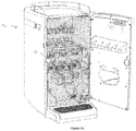
- FIG 1a illustrates a beverage preparation apparatus 1 of the state of the art, the front door being opened to enable an operator to start cleaning.
- the frame of the apparatus supports five containers 2 storing difference soluble beverage ingredients
- the outlets 21 of these containers dispense doses of ingredients in three dissolution chambers 3 positioned downwardly.
- These chambers prepare beverages and the beverages are dispensed through beverage tubes hold in a manifold 8.
- the beverages are dispensed in a cup that can be positioned on a drip tray at the bottom of the apparatus.
- the cleaning of such an apparatus requires that each chamber 3 is removed from the apparatus one after the other and that each chamber is further dismantled. After dismantling, cleaning and reassembling, each chamber must positioned back at the right original place in the apparatus.
- Figure 1b illustrates the apparatus at the step where the chambers 3, the manifold x and even the containers 2 have been removed so that the operator is about cleaning the internal parts of the frame of the apparatus. It can be noticed that the surfaces of the frame present many hidden recesses and edges making he cleaning tedious.
- FIGs 2a-2c are a schematic views of a beverage preparation apparatus according to the invention.
- the dispenser is represented according to a vertical cross section side view and a front view.
- the apparatus 10 is in its operational state ready to prepare beverages. It comprises three containers 2 storing soluble beverage ingredients. These ingredients are of different natures such as coffee, milk, decaffeinated coffee or not. Preferably these containers comprise or cooperate with dosing devices to dose and dispense the stored ingredient downwardly in three corresponding dissolution chambers 3. The doses of ingredient are introduced through the tops of the chambers. Each chamber 3 is designed for mixing the dose of beverage ingredient with a diluent to prepare the beverage.
- the diluent is introduced in each chamber 3 through a top diluent inlet 31a and a bottom diluent inlet 31b.
- the chamber comprises the bottom diluent inlet 31b only.
- Each diluent inlet is connected to the diluent supply system 4 hold inside the frame 1 of the apparatus.
- Each chamber 3 comprises a beverage outlet and each beverage outlet is connected to a flexible tube 61 that is part of a pinching valve as described hereunder.
- the apparatus comprises three pinching actuators 62 able to pinch the flexible tube as illustrated in Figure 2a . These actuators 62 are hold in the main frame 1 of the apparatus.
- the apparatus comprises a main frame 1 that holds at least the containers 2 and the diluent supply system 4.
- Figure 2b illustrates the apparatus in the state where the operator begins the cleaning operation.
- the three chambers are hold by a sub-frame 5.
- This sub-frame is attached to the main frame 1 in Figure 2a , but can be removed from the main frame as illustrated in Figure 2b .
- the sub-frame is pulled horizontally away from the frame and, in one movement, the three chambers are disconnected from the diluent system supply and removed from the apparatus.
- the part of the frame in which the sub-frame is positioned is a receiving area 7 forming a cavity inside the apparatus. This cavity presents a front face 72 and lateral faces 73.
- the front face 75 comprises holes 71a, 71b communicating with the diluent supply system 4 and establishing fluid connection with the different diluent inlets of the chambers, respectively 31a, 31b.
- the front face comprises only three holes 71b.
- the sub-frame 5 is a drawer sliding horizontally inside the receiving area 7.
- the lateral faces 72 comprise slots 74 in which lateral guiding rails 59 of the drawer can slide. Once the sub-frame has been removed, and as illustrated in Figure 2c , this receiving area 7 is fully accessible and easy to clean.
- the front face 72 is essentially flat since it comprises small holes 71b, and eventually the holes 71a, and the pinching actuators 62 are retracted behind the surface of the receiving area.
- the beverage outlets of the chambers are not connected to a flexible tube that is part of a pinching valve and the apparatus does not comprise pinching actuators.
- the front face 72 comprises only the holes 71a, 71b, and even more preferably only 71b, establishing connection with the diluent supply system 4.
- Figures 3a-3b illustrate an embodiment of the sub-frame 5 holding three chambers 3 according to the first mode.
- the sub-frame comprises three sub-areas 51 in which one chamber can be positioned. In particular the chambers can be slid from above in three rings guiding the movement of the operator.
- the sub-frame presents three slots 52. Each slot is designed to receive the bottom diluent inlet 31b of one chamber. These slots enable the correct orientation of the diluent inlet in the sub-frame, preferably in order to orientate the diluent inlets 31b perpendicularly to the back side of the sub-frame.
- the sub-frame comprises three indentations 53 enabling too the other top diluent inlets 31a to nest in the sub-frame.
- the chambers are well immobilised and oriented inside the sub-frame.
- the back side of the sub-frame comprises three holes 56 enabling the introduction and removal of the pinching actuators to pinch the flexible tubes hold in the sub-frame. Downstream the flexible tubes 61, conduits drive the beverages to the final dispensing outlets 57.
- the three outlets dispense their beverages in the same area, for example in the same cup.
- the three outlets can be designed to dispense their beverages in different areas, for example in three different cups.
- Figure 4 illustrates the sub-frame of Figures 3a-b the chambers being removed therefrom.
- the bottom part of the sub-frame comprises three conduits 54 designed to cooperate with the beverage outlet 33 (see Figures 5a-b ) of the chambers and leading to the flexible tubes of the pinching valves.
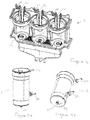
- Figures 5a -b are side and bottom views of one chamber 3.
- the chamber can comprise a slot 33 designed and positioned to fit with a corresponding bump 55 at the bottom part of one sub-area 51 of the sub-frame.
- This couple of slot and bump enables the positioning of the chambers always in the same sub-area 51 in the sub-frame.
- This embodiment is useful if the chambers present different internal configurations configured for specific natures of ingredients. It is important that the correct chamber is positioned under the correct ingredient containers and that after cleaning the chamber is positioned again at the same sub-area and under the same ingredient container. In place of the couple of slot and bump, the same code colour can be used for the chamber and its sub-area.
- Figure 6 is a perspective view of a sub-frame according to the second mode of the invention.
- the sub-frame 5 holds two dissolution chambers 3A, 3B and the assembly of the sub-frame 5 and the two chambers 3A, 3B is made of one single piece of material.
- the two chambers are attached one to the other by the external surfaces of their lateral side walls 34A, 34B.
- guiding rails 59 are moulded on the external surface of their lateral side walls 34A, 34B. Both chambers present different designs, in particular to dissolve different ingredients, such as instant coffee and milk powder.
- the front face of the receiving area comprises holes positioned to enable the connection of the three diluent inlets 31, 31a and 31b with the diluent supply.
- the operator can remove simultaneously both chambers and simultaneously rinse them and then put them in a dish washer.
- a second identical sub-frame can be provided to enable the operator to have the apparatus operational immediately.
- the sub-frame is illustrated with two different chambers. Yet in a variant, the two chambers can present the same design and can be configured for dissolving the same ingredient.
- Figures 7a and 7b are side views of a set of two sub-frames 5, 5' similar to the sub-frame described in Figure 6 except that the diluent inlets 31 of the chambers are always positioned at the same position of the chamber.
- the two chambers 3A, 3B present different designs, in particular to dissolve different ingredients, such as instant coffee and milk powder
- the two chambers 3B, 3B present the same design and are configured to dissolve the same ingredient such as milk powder.
- the diluents inlets 31 are always positioned at the same position of the sub-frame.
- both sub-frames 5, 5' can be alternatively used in the same apparatus wherein the front face of the receiving area comprises holes positioned to receive the diluent inlets 31 of the chambers.
- the operator is able to customise the beverages proposed in the beverage preparation apparatus and when the sub-frame 5 is used, the sub-frame 5' can be washed.
- the designs of the chambers 3A, 3B can also simply differ by the position of the beverage outlets 32.
- both outlets 32 are designed to dispense the beverages at the same place, meaning that only one receptacle can be positioned under these outlets.
- the outlets 32 can be designed to dispense the beverages at different places, meaning that one receptacle can be positioned under each outlet and that two beverages can be dispensed simultaneously.
Landscapes
- Engineering & Computer Science (AREA)
- Food Science & Technology (AREA)
- Apparatus For Making Beverages (AREA)
Abstract
The invention concerns a beverage preparation apparatus (10) comprising a main frame (1) supporting the functional components of the apparatus, part of said components comprising :
- a diluent supply system (4),
- at least two containers (2), said containers being configured for storing soluble beverage ingredients,
- at least two dissolution chambers (3) configured for preparing a beverage from a dose of soluble beverage ingredient and a dose of diluent, each dissolution chamber comprising :
• at last one diluent inlet (31a, 31b) designed to removably cooperate with the diluent supply system,
• one ingredient inlet (30) designed to receive the dose of soluble beverage ingredient,
• one beverage dispensing outlet (32),
wherein the apparatus comprises a sub-frame (5), said sub-frame being configured for holding all the dissolution chambers (2) and, said sub-frame being removably attached to the main frame (1).
- a diluent supply system (4),
- at least two containers (2), said containers being configured for storing soluble beverage ingredients,
- at least two dissolution chambers (3) configured for preparing a beverage from a dose of soluble beverage ingredient and a dose of diluent, each dissolution chamber comprising :
• at last one diluent inlet (31a, 31b) designed to removably cooperate with the diluent supply system,
• one ingredient inlet (30) designed to receive the dose of soluble beverage ingredient,
• one beverage dispensing outlet (32),
wherein the apparatus comprises a sub-frame (5), said sub-frame being configured for holding all the dissolution chambers (2) and, said sub-frame being removably attached to the main frame (1).
Description
- The present invention relates to beverage dispensers preparing beverages from a soluble beverage ingredient and in which a dose of said ingredient is mixed with a liquid in a mixing chamber.
- In the field of beverage preparation apparatus, the biggest apparatus enable the preparation of different types of beverages depending on the selection made by the consumer. For example, such apparatus enable alternatively the preparation of coffee, milk, chocolate or tea and mixtures of said beverages, usually mixtures of milk with coffee, chocolate or tea.
In order to provide this large choice of different beverages, the apparatus comprises several containers sorting separately different beverage ingredients such as coffee, tea, milk and chocolate soluble powders and several dissolution chambers dedicated to the preparation of the different beverages.
The internal parts of the apparatus must be regularly cleaned in order to avoid the growth of bacteria due to residues of beverages in the machine and clogging. Cleaning operation usually concerns the following parts of the dispenser: - each dissolution chamber must be thoroughly cleaned. Each chamber must be disconnected and dismantled during this operation.
- when all the chambers are disconnected from the apparatus, the internal parts of the machine are accessible and must be cleaned too.
- There is a need for improving the cleaning operation of beverage preparation apparatus.
- It would be advantageous to enable the operator to prepare ready-to-use assemblies of several beverage dissolution chamber.
- It would be advantageous to enable the operator to rapidly customise the beverage offer of the apparatus at the step of maintenance of the apparatus.
- In a first aspect of the invention, there is provided a beverage preparation apparatus comprising a main frame supporting the functional components of the apparatus. A part of said components comprises :
- a diluent supply system,
- at least two containers, said container being configured for storing soluble beverage ingredients,
- at least two dissolution chambers configured for preparing a beverage from a dose of soluble beverage ingredient and a dose of diluent, each dissolution chamber comprising :
- at last one diluent inlet designed to removably cooperate with the diluent supply system,
- one ingredient inlet designed to receive the dose of soluble beverage ingredient,
- one beverage dispensing outlet.
- The beverage dispenser of the present invention comprises a main frame in which the different functional elements for preparing the beverages are positioned.
- In particular, the main frame supports the diluent supply system providing the diluent to prepare the beverages. The diluent can be any suitable liquid adapted for dissolving a soluble beverage ingredient. A preferred diluent is water either hot or cold. Generally the diluent supply system of the apparatus comprises at least a diluent tank or diluent supply (such as tap water), a diluent pump, a diluent heater and/or cooler and valves for actuating the diluent delivery. The system can also comprise a selection valve for delivering diluent at either hot or cold temperature.
- The main frame supports at least two containers, said container being configured for storing soluble beverage ingredients. Usually each container comprises a storing tank and an ingredient outlet. Usually the outlet is positioned at the bottom of the tank.
- Usually, the apparatus comprises at least one soluble beverage ingredient dosing device, preferably one dosing device per container. The dosing device delivers the dosed ingredient to the dissolution chamber.
When the ingredient is a powder, the dosing device is preferably a rotatable volumetric dosing member. The devices for dosing can be comprised in the list of a dosing screw, a dosing auger or perforated discs. Depending on the type of container the dosing device can be integrated inside the container or provided at the outlet of the container. According to the preferred embodiment the dosing device is placed inside the container and positioned at the bottom of the container. It is preferably a spring or screw auger. Such augers displace a volume of powder from the container to the powder outlet. This sub-assembly composed of the container and the dosing device is usually identified as a canister in current beverage dispensers.
When the ingredient is a concentrate, the dosing device is preferably a peristaltic pump cooperating with a flexible tube filled with the concentrate. - The main frame supports at least two dissolution chambers configured for preparing a beverage from a dose of soluble beverage ingredient and a dose of diluent.
Each dissolution chamber comprises : - at least one diluent inlet designed to removably cooperate with the diluent supply system of the apparatus. The removable cooperation enables the removal of the chamber from the apparatus in order to clean it.
- one ingredient inlet designed to receive the dose of soluble beverage ingredient. Preferably each chamber cooperates with one dedicated container and receives a dose of ingredient therefrom. Yet in a variant, one chamber can cooperate with two dedicated containers.
- one beverage dispensing outlet. Usually, the dispensing outlet is positioned at the bottom of the chamber.
- In addition, the apparatus comprises a sub-frame. This sub-frame is supported by the main frame and is configured for holding all the dissolution chambers.
The sub-frame is removably attached to the main frame.
Accordingly, when the sub-frame is removed from the main frame of the apparatus, all the chambers are simultaneously removed from the apparatus. In one gesture, the operator removes all the chambers and gets a full and direct access to the internal parts of the apparatus hidden behind the chambers. - Preferably, the sub-frame is positioned in a receiving area of the main frame and this receiving area forms a cavity inside the apparatus. This cavity presents a front face and lateral faces, these lateral faces extending inside the apparatus back to said front face.
As a result, the receiving area defines a volume inside the apparatus for positioning and holding the sub-frame - and implicitly the chambers hold in the sub-frame - inside the apparatus.
Usually, the sub-frame and the receiving area comprise cooperating guiding means in order to enable a better handling of the sub-frame during the withdrawal from or the introduction in the main frame. The sub-frame can be correctly introduced and positioned inside the receiving area
Preferably, the apparatus comprises a locking device in order to firmly attached the sub-frame to the receiving area during the operation of the apparatus. The locking device can be a lever.
Preferably the sub-frame is a drawer and the drawer is able to slide horizontally in the receiving area of the main frame.
Preferably the front face of the receiving area is essentially flat and smooth. By essentially flat it is meant that the front face does not comprise parts jutting out and creating edges. Yet, the front face can comprise holes, in particular holes communicating with the diluent supply system. The global shape of this front face can be curved, the curvature presenting a radius of at least 40 mm.
Such front faces enable an extremely fast and easy cleaning of this surface for the operator for example by simply wiping with a cloth. - According to the preferred embodiment, for each dissolution chamber, the at least one diluent inlet comprises a conduit extending outside the chamber, said conduit presenting a length such that the conduit extends outside the external surface of the sub-frame when the chamber is hold in the sub-frame, and
wherein the front face of the receiving area comprises holes communicating with the diluent supply system, and
wherein the conduit of each chamber fits in one corresponding hole in the front face of the receiving area when the sub-frame is positioned in the receiving area.
Accordingly, since the front face comprises only holes to connect the diluent inlets of the chamber to the liquid supply system, the surface of the receiving area remains essentially flat and easy to clean. - Preferably the sub-frame can comprise sub-areas, each of these sub-areas being configured for holding one dissolution chamber and for orienting the conduit of the at least one diluent inlet of said chamber so that each conduit of each dissolution chamber is able to enter a corresponding hole in the surface of the receiving area.
Consequently, the connection of several chambers to the apparatus can be made in one easy gesture only.
Preferably, the conduits are oriented perpendicularly to the back face of the sub-frame. This embodiment makes connection easy, in particular when the sub-frame is a drawer. - According to one mode, the chambers are removable from the sub-frame. Consequently, once the sub-frame has been removed from the apparatus, it becomes easy to separate each chamber from the sub-frame. The operator is able to operate on a table or one side of a sink. Inconvenient handling inside the apparatus is not necessary any longer.
Preferably the sub-frame comprises sub-areas, each of these sub-areas being configured for receiving one dissolution chamber and for orienting the conduit of the at least one diluent inlet of said chamber.
Preferably, for all the chambers, the conduit of the at least one diluent inlet is a positioned at the same place at the outside of the chamber and oriented in the same direction.
Each sub-area is configured for orienting the conduit of the at least one diluent inlet of the chamber. The orientation of the conduit is defined in order to enable this conduit to easily fit inside the corresponding hole of the receiving area in the apparatus so as to provide connection with the liquid supply system. Preferably, the sub-area is configured for orienting the conduit perpendicularly to the back face of the sub-frame. With that aim, each of the sub-areas of the sub-frame can comprise a longitudinal slot to hold the conduit.
In one embodiment, each sub-areas presents a top opening, through which each chamber can slide. In that embodiment, preferably the chambers present a cylindrical external aspect - According to one second mode, the at least two dissolution chambers can be attached in the sub-frame in a non-dismountable manner.
Preferably, the at least two dissolution chambers and the sub-frame are made of one single piece of material. The sub-frame can be injection molded.
In that mode, the operator does not need to dismount the chambers from the sub-frame for cleaning, the whole sub-frame can be cleaned in the same operation, for example in a dishwasher. With that embodiment, the operations of dismantling the chambers from the sub-frame and re-assembling them after cleaning do not happen saving time for the operator.
A set of different sub-frames can be provided so that the operator is able to customise the beverage proposed in the beverage preparation apparatus. For example, one sub-frame can comprise two chambers both designed for preparing coffee in dispensing coffees in different drinking receptacles and another sub-frame can comprise one chamber designed for preparing coffee and one chamber for preparing foamed milk in the same drinking receptacle. - Whatever the mode, at least two dissolution chambers can differ by their internal configurations. This is the case when one chamber is configured for preparing coffee and another chamber is configured for preparing milk. Such chambers can differ by :
- their internal volume, and usually their internal diameter if the chambers are cylindrical, and/or
- the design of their internal surface, and/or
- the orientation of the diluent inlet inside the chamber. Actually, the jet of water provided by the diluent inlet can be inclined differently inside the chamber depending on the required dissolution effect, and/or
- the cross section and/or the shape of the beverage dispensing outlet.
- According to one embodiment of the apparatus :
- the dispensing outlet of each chamber communicates with a flexible tube, and
- each flexible tube is part of the sub-frame, and
- for each flexible tube, the apparatus comprises a corresponding pinching actuator able to slide in and out of the surface of the receiving area.
- In a second aspect of the invention, there is provided a system of :
- a beverage preparation apparatus, said apparatus comprising a main frame supporting the functional components of the apparatus, part of said components comprising :
- a diluent supply system,
- at least two containers, said containers being configured for storing soluble beverage ingredients,
- a receiving area configured for removably positioning a sub-frame under the containers, and
- at least two sub-frames, said sub-frame being configured for holding a combination of at least two dissolution chambers said chambers being configured for preparing a beverage from a dose of soluble beverage ingredient and a dose of diluent, each dissolution chamber comprising :
- at last one diluent inlet designed to removably cooperate with the diluent supply system,
- one ingredient inlet designed to receive the dose of soluble beverage ingredient,
- one beverage dispensing outlet,
- Alternatively or in addition to, the system can comprise a multiplicity of sub-frames, the sub-frames differing by the combination of chambers hold inside. The combinations of chambers from one sub-frame to another can differ by the beverage offer they provide. For example, one sub-frame can comprise two chambers designed for preparing coffee and dispensing coffees in different drinking receptacles and another sub-frame can comprise one chamber designed for preparing coffee and one chamber for preparing foamed milk in the same drinking receptacle. These sub-frames can be used at different hours of the day depending on the demand of the consumers : the demand for black coffees is stronger in the morning whereas the demand for cappuccinos is stronger after the lunch. The two sub-frames enables the operator to change easily from one offer to the other in the course of the day, to clean the dirty chambers and to get them ready to use for the next day.
- Preferably the combination of at least two dissolution chambers and the sub-frame are made of one single piece of material.
- The beverage ingredient used in the apparatus of the present invention can be a soluble beverage powder or a beverage concentrate.
Such a soluble beverage powder can be instant coffee powder, chocolate powder, milk powder, instant tea powder, a fruit powder, a soup powder.
Such a beverage concentrate can be a coffee concentrate, milk concentrate, tea concentrate, a syrup. - In the present application the terms "internal", "external", "back", "front", "bottom", "lateral" and "top" are used to describe the relational positioning of features of the invention. These terms should be understood to refer to the components of the apparatus in their normal orientation when positioned in the apparatus for the production of a beverage as shown in the
figures 2a-c ,3a-b ,6 and7a-b . - The above aspects of the invention may be combined in any suitable combination. Moreover, various features herein may be combined with one or more of the above aspects to provide combinations other than those specifically illustrated and described. Further objects and advantageous features of the invention will be apparent from the claims, from the detailed description, and annexed drawings.
- The characteristics and advantages of the invention will be better understood in relation to the following figures :
-
Figures 1a and1b illustrate a beverage preparation apparatus according to the state of the art during the cleaning operation -
Figures 2a-2c are a schematic view of an apparatus according to the invention in different operational states, -
Figures 3a-3b are perspective views of the front and back sides of an embodiment of the sub-frame holding three chambers, -
Figure 4 illustrates the sub-frame ofFigures 3a-b without the chambers, -
Figures 5a-b are side and bottom views of one chamber. -
Figure 6 is a perspective view of a sub-frame according to the second mode of the invention, -
Figures 7a and 7b are side views of a set of two sub-frames according to the second mode of the invention. -
Figure 1a illustrates abeverage preparation apparatus 1 of the state of the art, the front door being opened to enable an operator to start cleaning.
Internally, the frame of the apparatus supports fivecontainers 2 storing difference soluble beverage ingredients The outlets 21 of these containers dispense doses of ingredients in threedissolution chambers 3 positioned downwardly. These chambers prepare beverages and the beverages are dispensed through beverage tubes hold in a manifold 8. The beverages are dispensed in a cup that can be positioned on a drip tray at the bottom of the apparatus.
The cleaning of such an apparatus requires that eachchamber 3 is removed from the apparatus one after the other and that each chamber is further dismantled. After dismantling, cleaning and reassembling, each chamber must positioned back at the right original place in the apparatus.
In another step, the manifold 8 is dismantled too, cleaned, reassembled and positioned back in the apparatus.
Figure 1b illustrates the apparatus at the step where thechambers 3, the manifold x and even thecontainers 2 have been removed so that the operator is about cleaning the internal parts of the frame of the apparatus. It can be noticed that the surfaces of the frame present many hidden recesses and edges making he cleaning tedious. -
Figures 2a-2c are a schematic views of a beverage preparation apparatus according to the invention. In each Figure, the dispenser is represented according to a vertical cross section side view and a front view.
InFigure 2a , theapparatus 10 is in its operational state ready to prepare beverages. It comprises threecontainers 2 storing soluble beverage ingredients. These ingredients are of different natures such as coffee, milk, decaffeinated coffee or not. Preferably these containers comprise or cooperate with dosing devices to dose and dispense the stored ingredient downwardly in threecorresponding dissolution chambers 3. The doses of ingredient are introduced through the tops of the chambers. Eachchamber 3 is designed for mixing the dose of beverage ingredient with a diluent to prepare the beverage. The diluent is introduced in eachchamber 3 through a topdiluent inlet 31a and abottom diluent inlet 31b. Yet, according to the preferred embodiment, the chamber comprises thebottom diluent inlet 31b only. Each diluent inlet is connected to the diluent supply system 4 hold inside theframe 1 of the apparatus. Eachchamber 3 comprises a beverage outlet and each beverage outlet is connected to aflexible tube 61 that is part of a pinching valve as described hereunder.
The apparatus comprises three pinchingactuators 62 able to pinch the flexible tube as illustrated inFigure 2a . Theseactuators 62 are hold in themain frame 1 of the apparatus.
The apparatus comprises amain frame 1 that holds at least thecontainers 2 and the diluent supply system 4.
Figure 2b illustrates the apparatus in the state where the operator begins the cleaning operation. The three chambers are hold by asub-frame 5. This sub-frame is attached to themain frame 1 inFigure 2a , but can be removed from the main frame as illustrated inFigure 2b . After opening the front door of the apparatus and eventually unlocked the sub-frame, the sub-frame is pulled horizontally away from the frame and, in one movement, the three chambers are disconnected from the diluent system supply and removed from the apparatus. The part of the frame in which the sub-frame is positioned is a receiving area 7 forming a cavity inside the apparatus. This cavity presents afront face 72 and lateral faces 73. The front face 75 comprises holes 71a, 71b communicating with the diluent supply system 4 and establishing fluid connection with the different diluent inlets of the chambers, respectively 31a, 31b. According to the preferred embodiment, the front face comprises only three holes 71b. In this illustrated embodiment, thesub-frame 5 is a drawer sliding horizontally inside the receiving area 7. The lateral faces 72 compriseslots 74 in which lateral guiding rails 59 of the drawer can slide.
Once the sub-frame has been removed, and as illustrated inFigure 2c , this receiving area 7 is fully accessible and easy to clean. In particular thefront face 72 is essentially flat since it comprises small holes 71b, and eventually the holes 71a, and the pinchingactuators 62 are retracted behind the surface of the receiving area.
In the preferred embodiment, the beverage outlets of the chambers are not connected to a flexible tube that is part of a pinching valve and the apparatus does not comprise pinching actuators. As a result thefront face 72 comprises only the holes 71a, 71b, and even more preferably only 71b, establishing connection with the diluent supply system 4. -
Figures 3a-3b illustrate an embodiment of thesub-frame 5 holding threechambers 3 according to the first mode. The sub-frame comprises three sub-areas 51 in which one chamber can be positioned. In particular the chambers can be slid from above in three rings guiding the movement of the operator. On the back side, the sub-frame presents threeslots 52. Each slot is designed to receive thebottom diluent inlet 31b of one chamber. These slots enable the correct orientation of the diluent inlet in the sub-frame, preferably in order to orientate thediluent inlets 31b perpendicularly to the back side of the sub-frame. Consequently, when the operator positions the sub-frame in the receiving area of the frame, the movement of the operator is a horizontal sliding movement enabling easy connection of the diluent inlets with the holes in the surface of the receiving area.
The sub-frame comprises threeindentations 53 enabling too the other topdiluent inlets 31a to nest in the sub-frame.
The chambers are well immobilised and oriented inside the sub-frame.
The back side of the sub-frame comprises threeholes 56 enabling the introduction and removal of the pinching actuators to pinch the flexible tubes hold in the sub-frame. Downstream theflexible tubes 61, conduits drive the beverages to thefinal dispensing outlets 57. In the illustrated embodiment, the three outlets dispense their beverages in the same area, for example in the same cup. Alternatively, the three outlets can be designed to dispense their beverages in different areas, for example in three different cups. -
Figure 4 illustrates the sub-frame ofFigures 3a-b the chambers being removed therefrom. The bottom part of the sub-frame comprises threeconduits 54 designed to cooperate with the beverage outlet 33 (seeFigures 5a-b ) of the chambers and leading to the flexible tubes of the pinching valves. -
Figures 5a -b are side and bottom views of onechamber 3. At its bottom, the chamber can comprise aslot 33 designed and positioned to fit with a corresponding bump 55 at the bottom part of onesub-area 51 of the sub-frame. This couple of slot and bump enables the positioning of the chambers always in thesame sub-area 51 in the sub-frame. This embodiment is useful if the chambers present different internal configurations configured for specific natures of ingredients. It is important that the correct chamber is positioned under the correct ingredient containers and that after cleaning the chamber is positioned again at the same sub-area and under the same ingredient container. In place of the couple of slot and bump, the same code colour can be used for the chamber and its sub-area. -
Figure 6 is a perspective view of a sub-frame according to the second mode of the invention.
Thesub-frame 5 holds twodissolution chambers sub-frame 5 and the twochambers lateral side walls sub-frame 5, guidingrails 59 are moulded on the external surface of theirlateral side walls diluent inlets
The sub-frame is illustrated with two different chambers. Yet in a variant, the two chambers can present the same design and can be configured for dissolving the same ingredient. -
Figures 7a and 7b are side views of a set of twosub-frames 5, 5' similar to the sub-frame described inFigure 6 except that thediluent inlets 31 of the chambers are always positioned at the same position of the chamber. In thesub-frame 5, the twochambers chambers sub-frames 5, 5', whatever the design of thechambers diluents inlets 31 are always positioned at the same position of the sub-frame.
As a result, bothsub-frames 5, 5' can be alternatively used in the same apparatus wherein the front face of the receiving area comprises holes positioned to receive thediluent inlets 31 of the chambers. With this set ofdifferent sub-frames 5, 5', the operator is able to customise the beverages proposed in the beverage preparation apparatus and when thesub-frame 5 is used, the sub-frame 5' can be washed.
In a variant, the designs of thechambers beverage outlets 32. InFigures 7a and 7b , bothoutlets 32 are designed to dispense the beverages at the same place, meaning that only one receptacle can be positioned under these outlets. In the variant, theoutlets 32 can be designed to dispense the beverages at different places, meaning that one receptacle can be positioned under each outlet and that two beverages can be dispensed simultaneously. - Although the invention has been described with reference to the above illustrated embodiments, it will be appreciated that the invention as claimed is not limited in any way by these illustrated embodiments.
Variations and modifications may be made without departing from the scope of the invention as defined in the claims. Furthermore, where known equivalents exist to specific features, such equivalents are incorporated as if specifically referred in this specification.
As used in this specification, the words "comprises", "comprising", and similar words, are not to be interpreted in an exclusive or exhaustive sense. In other words, they are intended to mean "including, but not limited to". -
- beverage preparation apparatus
- 10
- frame
- 1
- container
- 2
- chamber
- 3, 3A, 3B
- ingredient inlet
- 30
- diluent inlet
- 31, 31a, 31b
- conduit
- 311a, 311b
- beverage outlet
- 32
- recess
- 33
- lateral side wall
- 34A, 34B
- diluent supply system
- 4
- sub-frame
- 5, 5'
- sub-areas
- 51
- slot
- 52
- indentation
- 53
- outlet
- 54
- bump
- 55
- holes
- 56
- final dispensing outlets
- 57
- back side
- 58
- guiding rail
- 59
- flexible tube
- 61
- pinching actuator
- 62
- receiving area
- 7
- holes
- 71a, 71b
- front face
- 72
- lateral face
- 73
- slot
- 74
- manifold
- 8
This operation takes time and it must done by people that have been trained for the disassembling and the reassembling to avoid errors and further failure in the beverages production. Usually this cleaning is made by an operator dedicated to the maintenance of the beverages production machines.
Now there is need for decreasing the time for the cleaning operation to limit the period of time during which the dispenser is not operable. There is also a need for having this operation made by any non-trained person so that it is not necessary to ask a specific operator to come and clean the machine. The cleaning should be made by any person briefly trained on the cleaning operations. This cleaning operation must also be so short that he can be made more often depending on the nature of the food ingredients.
Preferably, the dissolution chamber can comprise at least one diluent inlet configured for introducing the diluent in the form of a jet inside the chamber. The chamber is preferably configured so that a whirlpool of liquid is created in the chamber and the jet of diluent hits said whirlpool. Such a dissolution chamber is described in
Preferably, the chamber is devoid of whipper because whipper require more time for cleaning : indeed, a whipper is an additional piece of material to be cleaned, and whipper requires a connection to a motor, which complicates the dismantling of the chamber.
Usually the dissolution chamber is positioned under the outlet of the container so that the ingredient can be dispensed from a container in the chamber by gravity fall.
Generally the top of the dissolution chamber is opened so that powder can freely flow inside by gravity fall. By opened it is meant that the top of the chamber is not covered e.g. by a lid.
This system presents the advantage of providing several ready-to-use sub-frames for the same apparatus. Accordingly, one sub-frame can be introduced and used in the apparatus while another one can be quietly cleaned in the meantime. These sub-frames can present the same combination of chambers.
Claims (16)
- Beverage preparation apparatus (10) comprising a main frame (1) supporting the functional components of the apparatus, part of said components comprising :- a diluent supply system (4),- at least two containers (2), said containers being configured for storing soluble beverage ingredients,- at least two dissolution chambers (3) configured for preparing a beverage from a dose of soluble beverage ingredient and a dose of diluent, each dissolution chamber comprising :. at last one diluent inlet (31a, 31b) designed to removably cooperate with the diluent supply system,. one ingredient inlet (30) designed to receive the dose of soluble beverage ingredient,. one beverage dispensing outlet (32),wherein the apparatus comprises a sub-frame (5), said sub-frame being configured for holding all the dissolution chambers (2) and, said sub-frame being removably attached to the main frame (1).
- Beverage preparation apparatus according to Claim 1, wherein the sub-frame (5) is positioned in a receiving area (7) of the main frame, said receiving area (7) forming a cavity inside the apparatus, said cavity presenting a front face (72) and lateral faces (73), said lateral faces extending inside the apparatus back to said front face.
- Beverage preparation apparatus according to the precedent claim, wherein the sub-frame (5) is a drawer and the drawer is able to slide horizontally in the receiving area (7) of the main frame.
- Beverage preparation apparatus according to Claim 2 or 3, wherein the front face (72) of the receiving area is essentially flat and smooth.
- Beverage preparation apparatus according to any one of Claims 2 to 4, wherein, for each dissolution chamber (3), the at least one diluent inlet (31a, 31b) comprises a conduit (311a, 311b) extending outside the chamber, said conduit presenting a length such that the conduit extends outside the external surface of the sub-frame when the chamber is hold in the sub-frame, and
wherein the front face (72) of the cavity of the receiving area comprises holes (71a, 71b) communicating with the diluent supply system (4), and
wherein the conduit (311a, 311b) of each chamber fits in one corresponding hole (71a, 71b) in the surface of the receiving area when the sub-frame is positioned in the receiving area. - Beverage preparation apparatus according to the precedent claim, wherein the sub-frame (5) comprises sub-areas (51), each of these sub-areas being configured for holding one dissolution chamber (3) and for orienting the conduit (71a, 71b) of the at least one diluent inlet of said chamber so that each conduit of each dissolution chamber is able to enter a corresponding hole (71a, 71b) in the surface of the receiving area.
- Beverage preparation apparatus according to any one of the precedent claims, wherein the chambers (3) are removable from the sub-frame (5).
- Beverage preparation apparatus according to any one of Claims 6 or 7, wherein all the chambers (3) present the same external configuration.
- Beverage preparation apparatus according to and one of Claims 5 to 8, wherein, for all the chambers (3), the conduit (71a, 71b) of the at least one diluent inlet is a positioned at the same place, and the external volume of the chamber is the same.
- Beverage preparation apparatus according to any one of the precedent claims, wherein at least two chambers (2) differ by their internal configurations.
- Beverage preparation apparatus according to any one of the precedent claims, wherein :- the beverage dispensing outlet (32) of each chamber communicates with a flexible tube (61), and- each flexible tube (61) is part of the sub-frame (5), and- for each flexible tube, the apparatus comprises a corresponding pinching actuator (62) able to slide in and out of the surface of the receiving area.
- Beverage preparation apparatus according to any one of Claim 1 to 3, wherein the at least two dissoluble chambers (3) are attached in the sub-frame (5) in a non-dismountable manner.
- Beverage preparation apparatus according to the precedent claim, wherein the at least two dissoluble chambers (3) and the sub-frame (5) are made of one single piece of material.
- System of :- a beverage preparation apparatus (10), said apparatus comprising a main frame (1) supporting the functional components of the apparatus, part of said components comprising :. a diluent supply system (4),. at least two containers (2), said containers being configured for storing soluble beverage ingredients,. a receiving area (7) configured for removably positioning a sub-frame (5) under the containers,
and- at least two sub-frames (5), each sub-frame being configured for holding a combination of at least two dissolution chambers (3), said chambers being configured for preparing a beverage from a dose of soluble beverage ingredient and a dose of diluent, each dissolution chamber comprising :. at last one diluent inlet (31a, 31b) designed to removably cooperate with the diluent supply system,. one ingredient inlet (30) designed to receive a dose of soluble beverage ingredient,. one beverage dispensing outlet (32)each chamber presenting an internal design configured to dissolve one dedicated type of soluble beverage ingredient. - System according to Claim 14, wherein the system comprises a multiplicity of sub-frames, the sub-frames differing by the combination of chambers hold inside.
- System according to Claim 14 or 15, wherein the combination of at least two dissoluble chambers (3) and the sub-frame (5) are made of one single piece of material.
Priority Applications (1)
| Application Number | Priority Date | Filing Date | Title |
|---|---|---|---|
| EP17210205.5A EP3501347A1 (en) | 2017-12-22 | 2017-12-22 | Beverage dispenser with a plurality of dissolution chambers |
Applications Claiming Priority (1)
| Application Number | Priority Date | Filing Date | Title |
|---|---|---|---|
| EP17210205.5A EP3501347A1 (en) | 2017-12-22 | 2017-12-22 | Beverage dispenser with a plurality of dissolution chambers |
Publications (1)
| Publication Number | Publication Date |
|---|---|
| EP3501347A1 true EP3501347A1 (en) | 2019-06-26 |
Family
ID=60782097
Family Applications (1)
| Application Number | Title | Priority Date | Filing Date |
|---|---|---|---|
| EP17210205.5A Withdrawn EP3501347A1 (en) | 2017-12-22 | 2017-12-22 | Beverage dispenser with a plurality of dissolution chambers |
Country Status (1)
| Country | Link |
|---|---|
| EP (1) | EP3501347A1 (en) |
Citations (6)
| Publication number | Priority date | Publication date | Assignee | Title |
|---|---|---|---|---|
| WO2003094681A1 (en) * | 2002-05-09 | 2003-11-20 | Rheavendors Spa | Machine for preparing beverages |
| WO2008067843A1 (en) * | 2006-12-18 | 2008-06-12 | Saeco Ipr Limited | Improvements in beverage vending machines |
| WO2008071613A1 (en) | 2006-12-11 | 2008-06-19 | Nestec S.A. | Device and method for producing a frothed liquid from soluble ingredients and diluent |
| US20120006204A1 (en) * | 2010-07-09 | 2012-01-12 | Crane Merchandising Systems, Inc. | Modular vending machine and cartridge system |
| WO2012136643A1 (en) * | 2011-04-05 | 2012-10-11 | Nestec S.A. | Set of modular beverage preparation machines and processes for configuring and manufacturing the machines |
| WO2016016240A1 (en) * | 2014-07-30 | 2016-02-04 | Nestec S.A. | Dispenser preparing beverages from powders |
-
2017
- 2017-12-22 EP EP17210205.5A patent/EP3501347A1/en not_active Withdrawn
Patent Citations (6)
| Publication number | Priority date | Publication date | Assignee | Title |
|---|---|---|---|---|
| WO2003094681A1 (en) * | 2002-05-09 | 2003-11-20 | Rheavendors Spa | Machine for preparing beverages |
| WO2008071613A1 (en) | 2006-12-11 | 2008-06-19 | Nestec S.A. | Device and method for producing a frothed liquid from soluble ingredients and diluent |
| WO2008067843A1 (en) * | 2006-12-18 | 2008-06-12 | Saeco Ipr Limited | Improvements in beverage vending machines |
| US20120006204A1 (en) * | 2010-07-09 | 2012-01-12 | Crane Merchandising Systems, Inc. | Modular vending machine and cartridge system |
| WO2012136643A1 (en) * | 2011-04-05 | 2012-10-11 | Nestec S.A. | Set of modular beverage preparation machines and processes for configuring and manufacturing the machines |
| WO2016016240A1 (en) * | 2014-07-30 | 2016-02-04 | Nestec S.A. | Dispenser preparing beverages from powders |
Similar Documents
| Publication | Publication Date | Title |
|---|---|---|
| RU2630758C2 (en) | Machines for preparation of beverages | |
| RU2500328C2 (en) | Coffee machine | |
| AU2011315486B2 (en) | Beverage dispenser with whipper assembly | |
| AU2018369579B2 (en) | A system for multi-ingredient beverage preparation from various container types | |
| EP2604152B1 (en) | Beverage dispenser with improved outlet tubes assembly | |
| AU2018387674B2 (en) | Beverage dispenser with a plurality of dissolution chambers | |
| AU2018387722B2 (en) | Beverage preparation machine with handy drop stop | |
| AU2018387158A1 (en) | Beverage preparation machine with foam refinement | |
| JP2018503452A (en) | System for refilling powder into a beverage dispenser | |
| EP3501347A1 (en) | Beverage dispenser with a plurality of dissolution chambers | |
| AU2018387159B2 (en) | Beverage preparation machine with drop evacuation | |
| US20240407586A1 (en) | Ergonomic beverage machine |
Legal Events
| Date | Code | Title | Description |
|---|---|---|---|
| PUAI | Public reference made under article 153(3) epc to a published international application that has entered the european phase |
Free format text: ORIGINAL CODE: 0009012 |
|
| AK | Designated contracting states |
Kind code of ref document: A1 Designated state(s): AL AT BE BG CH CY CZ DE DK EE ES FI FR GB GR HR HU IE IS IT LI LT LU LV MC MK MT NL NO PL PT RO RS SE SI SK SM TR |
|
| AX | Request for extension of the european patent |
Extension state: BA ME |
|
| RAP1 | Party data changed (applicant data changed or rights of an application transferred) |
Owner name: SOCIETE DES PRODUITS NESTLE S.A. |
|
| STAA | Information on the status of an ep patent application or granted ep patent |
Free format text: STATUS: THE APPLICATION HAS BEEN WITHDRAWN |
|
| 18W | Application withdrawn |
Effective date: 20190717 |