EP3500704B1 - Dual method subsea chemical delivery and pressure boosting - Google Patents
Dual method subsea chemical delivery and pressure boosting Download PDFInfo
- Publication number
- EP3500704B1 EP3500704B1 EP17776730.8A EP17776730A EP3500704B1 EP 3500704 B1 EP3500704 B1 EP 3500704B1 EP 17776730 A EP17776730 A EP 17776730A EP 3500704 B1 EP3500704 B1 EP 3500704B1
- Authority
- EP
- European Patent Office
- Prior art keywords
- fluid
- pump
- subsea
- flow
- power
- Prior art date
- Legal status (The legal status is an assumption and is not a legal conclusion. Google has not performed a legal analysis and makes no representation as to the accuracy of the status listed.)
- Active
Links
Images

Classifications
-
- E—FIXED CONSTRUCTIONS
- E21—EARTH OR ROCK DRILLING; MINING
- E21B—EARTH OR ROCK DRILLING; OBTAINING OIL, GAS, WATER, SOLUBLE OR MELTABLE MATERIALS OR A SLURRY OF MINERALS FROM WELLS
- E21B41/00—Equipment or details not covered by groups E21B15/00 - E21B40/00
- E21B41/02—Equipment or details not covered by groups E21B15/00 - E21B40/00 in situ inhibition of corrosion in boreholes or wells
-
- E—FIXED CONSTRUCTIONS
- E21—EARTH OR ROCK DRILLING; MINING
- E21B—EARTH OR ROCK DRILLING; OBTAINING OIL, GAS, WATER, SOLUBLE OR MELTABLE MATERIALS OR A SLURRY OF MINERALS FROM WELLS
- E21B41/00—Equipment or details not covered by groups E21B15/00 - E21B40/00
- E21B41/0007—Equipment or details not covered by groups E21B15/00 - E21B40/00 for underwater installations
-
- E—FIXED CONSTRUCTIONS
- E21—EARTH OR ROCK DRILLING; MINING
- E21B—EARTH OR ROCK DRILLING; OBTAINING OIL, GAS, WATER, SOLUBLE OR MELTABLE MATERIALS OR A SLURRY OF MINERALS FROM WELLS
- E21B33/00—Sealing or packing boreholes or wells
- E21B33/02—Surface sealing or packing
- E21B33/03—Well heads; Setting-up thereof
- E21B33/068—Well heads; Setting-up thereof having provision for introducing objects or fluids into, or removing objects from, wells
- E21B33/076—Well heads; Setting-up thereof having provision for introducing objects or fluids into, or removing objects from, wells specially adapted for underwater installations
-
- E—FIXED CONSTRUCTIONS
- E21—EARTH OR ROCK DRILLING; MINING
- E21B—EARTH OR ROCK DRILLING; OBTAINING OIL, GAS, WATER, SOLUBLE OR MELTABLE MATERIALS OR A SLURRY OF MINERALS FROM WELLS
- E21B34/00—Valve arrangements for boreholes or wells
-
- E—FIXED CONSTRUCTIONS
- E21—EARTH OR ROCK DRILLING; MINING
- E21B—EARTH OR ROCK DRILLING; OBTAINING OIL, GAS, WATER, SOLUBLE OR MELTABLE MATERIALS OR A SLURRY OF MINERALS FROM WELLS
- E21B37/00—Methods or apparatus for cleaning boreholes or wells
- E21B37/06—Methods or apparatus for cleaning boreholes or wells using chemical means for preventing or limiting, e.g. eliminating, the deposition of paraffins or like substances
Definitions
- Subsea oil and gas production wells typically require chemical treatment to help ensure the reservoir, production tubing, valves and pipelines remain in optimum condition for well flow and pressure integrity.
- Chemicals are typically delivered to the production wells thru an umbilical from the host facility to which the production is routed. Current methods require the chemicals to be stored and pressurized at the production host to a pressure exceeding that of the shut in pressure of the reservoir in one case and above flowing pressure of the reservoir in another. Exceeding the production pressure ensures the chemicals are delivered into the wellbore and pipeline system to commingle with the production flow.
- High pressure chemical delivery requires the delivery conduits in the control umbilical to be rated for these high pressures to both meet the injection pressure requirements locally at the wellsite.
- Each production reservoir is somewhat unique and requires a variety of chemicals and volumes to be delivered to keep the flow conduits in optimum condition. Corrosion, scale, paraffin, emulsifiers and others are a few of the chemicals used in relatively small volumes to treat the production flow. Some chemicals such as methanol, LDHI, monoethylene glycol are typically delivered in higher volumes to treat the production flow and inhibit the formation of hydrates in the production stream.
- US 2012/175125 A1 discloses a subsea oil and gas production Christmas tree control system, serviceable by an ROV subsea, comprises an umbilical and a system controller further comprising an HPU that comprises a manipulatable subsea housing; a subsea hydraulic fluid reservoir; a motor disposed in the housing; and a hydraulic power unit disposed in the housing.
- Hydrocarbon production may controlled subsea by deploying a modular subsea oil and gas production Christmas tree control system using an ROV; supplying the HPU with hydraulic fluid; providing a predetermined control to a subsea Christmas tree using a Christmas tree control system component; monitoring a Christmas tree control system status; enabling a redundant Christmas tree control system component upon detection of a fault in a Christmas tree control system component paired with the redundant component; and providing status data from the Christmas tree control system to a status data receiver using a data communications link.
- the disclosed invention removes chemical delivery conduits from an umbilical, and in some instances eliminates all fluid conduits from the umbilical, and requires only electrical power and/or data delivery to a well site.
- subsea fluid storage reservoirs are located on a seafloor adjacent to the well site for low fluid flow requirement chemicals necessary for the well.
- a subsea pumping system is typically included for boosting the chemical pressure from ambient to that required for injection into the production stream.
- low and high flow chemical delivery systems are segregated by use of subsea storage and pressure boosting for the low flow needs and a dedicated flowline from the host facility for the high flow needs.
- Subsea pressure boosting for the high fluid flow requirements can also be provided for allowing a low pressure flowline to be utilized and minimize cost.
- the modular approach offered by embodiments of the invention accommodates chemical storage and pumping systems expansion and modification.
- integrating the controls and monitoring of both the dual method fluid delivery system and the other subsea production system elements can simplify an umbilical system from a host facility.
- a modular subsea chemical injection system comprises one or more power and communication modules 20 operatively connected to one or more power and communications umbilicals 21, at least one power and communications umbilical 21 lacking a chemical delivery conduit; at least one power and communications umbilical terminator 22 operatively connected to umbilical 21; one or more power and communications modules 30; one or more fluid storage modules 40 operatively in communication with subsea electronics module 31 and electrical power distributor 32; one or more pump modules 50 operatively in communication with subsea electronics module 31 and electrical power distributor 32; and fluid distribution unit 60.
- Host facility 10 may be operatively connected to power and communications umbilical 21.
- subsea control module (SCM) 70 may be present, as more fully described below, where SCM 70 may further comprise SCM fluid port 72.
- Power and communication terminator 20 comprises electrical power port 24 (not shown in the figures) which may comprise low voltage power outlet 22, high voltage power outlet 23, or the like, or a combination thereof. Power and communications umbilical terminator 20 may further comprise data communications port 25. If SCM 70 is present, power and communications terminator 20 typically further comprises non-integral SCM power and data communications port 25 operatively in communication with SCM 70.
- At least one power and communications modules 30 comprises subsea electronics module 31 operatively in communication with power and communications umbilical terminator data communications port 23 and electrical power distributor 32 operatively in communication with power and communications umbilical terminator electrical power port 24. If SCM 70 is present, power and communications module 30 may further comprise integral SCM power and data communications port 35 operatively in communication with SCM 70.
- Fluid storage modules 40 typically comprise a plurality of fluid storage bays 41, each fluid storage bay 41 adapted to selectively receive a corresponding plurality of fluid storage tanks 42, and at least one fluid storage module fluid port 43 in fluid communication with one or more fluid storage tank 42.Not all fluid storage bays 41need to be populated at any given time.
- Pump module 50 typically comprises a plurality of pump bays 51 adapted to selectively receive a corresponding plurality of pumps 52, although not all pump bays 51 need to be populated at any given time. At least one pump 52 is in fluid communication with at least one fluid storage tank 42. In addition, pump module 50 further comprises one or more pump module fluid ports 54 in fluid communication with at least one pump 52. In embodiments, one or more high flow fluid ports 53 may be present in fluid communication with at least one pump 52.
- Fluid distribution unit 60 typically comprises at least one distribution fluid port 62 in fluid communication with at least one pump module fluid port 54, at least one fluid distribution unit fluid supply port 63 in fluid communication with distribution fluid port 62, and fluid metering valve 61 disposed intermediate distribution fluid port 62 and fluid distribution unit fluid supply port 63. If one or more subsea control modules (SCM) 70 are present, each SCM 70 is typically in fluid communication with fluid distribution unit fluid supply port 63 such as via port 71. In embodiments, each SCM 70 is in fluid communication with a separate fluid distribution unit fluid supply port 63.
- SCM subsea control modules
- subsea processing system 80 may be present and in fluid communication with fluid distribution unit fluid supply port 63 and/or SCM fluid port 72 such as via subsea processing system fluid inlet port 81.
- Subsea processing system 80 may further comprise fluid delivery booster 83 which may be in fluid communication with subsea processing system fluid inlet port 81. If host facility 10 is present, subsea processing system 80 may further comprise at least one subsea processing system fluid outlet port 82 in fluid communication with host facility 10 and, if fluid delivery booster 83 is present, with fluid delivery booster 83.
- a single standalone flowline 90 (composite, carbon steel, stainless) is connected from the surface host 10 to the subsea fluid distribution unit 60.
- Chemical startup fluid is pressurized via the surface host 10 and delivered at the required flow rate to the fluid distribution unit 60.
- a modular subsea chemical injection system comprises one or more power and communication modules 20 operatively connected to one or more power and communications umbilicals 21, at least one power and communications umbilical 21 lacking a chemical delivery conduit; at least one power and communications umbilical terminator 22 operatively connected to umbilical 21; one or more power and communications modules 30; one or more fluid storage modules 40 operatively in communication with subsea electronics module 31 and electrical power distributor 32; one or more pump modules 50 operatively in communication with subsea electronics module 31 and electrical power distributor 32; and fluid distribution unit 60.
- Host facility 10 may be operatively connected to power and communications umbilical 21.
- subsea control module (SCM) 70 may be present, as more fully described below, where SCM 70 may further comprise SCM fluid port 72.
- Power and communication terminator 20 comprises electrical power port 24 (not shown in the figures) which may comprise low voltage power outlet 22, high voltage power outlet 23, or the like, or a combination thereof. Power and communications umbilical terminator 20 may further comprise data communications port 25. If SCM 70 is present, power and communications terminator 20 typically further comprises non-integral SCM power and data communications port 25 operatively in communication with SCM 70.
- At least one power and communications modules 30 comprises subsea electronics module 31 operatively in communication with power and communications umbilical terminator data communications port 23 and electrical power distributor 32 operatively in communication with power and communications umbilical terminator electrical power port 24. If SCM 70 is present, power and communications module 30 may further comprise integral SCM power and data communications port 35 operatively in communication with SCM 70.
- Fluid storage modules 40 typically comprise a plurality of fluid storage bays 41, each fluid storage bay 41 adapted to selectively receive a corresponding plurality of fluid storage tanks 42, and at least one fluid storage module fluid port 43 in fluid communication with one or more fluid storage tank 42.Not all fluid storage bays 41need to be populated at any given time.
- Pump module 50 typically comprises a plurality of pump bays 51 adapted to selectively receive a corresponding plurality of pumps 52, although not all pump bays 51 need to be populated at any given time. At least one pump 52 is in fluid communication with at least one fluid storage tank 42. In addition, pump module 50 further comprises one or more pump module fluid ports 54 in fluid communication with at least one pump 52. In embodiments, one or more high flow fluid ports 53 may be present in fluid communication with at least one pump 52.
- Fluid distribution unit 60 typically comprises at least one distribution fluid port 62 in fluid communication with at least one pump module fluid port 54, at least one fluid distribution unit fluid supply port 63 in fluid communication with distribution fluid port 62, and fluid metering valve 61 disposed intermediate distribution fluid port 62 and fluid distribution unit fluid supply port 63. If one or more subsea control modules (SCM) 70 are present, each SCM 70 is typically in fluid communication with fluid distribution unit fluid supply port 63 such as via port 71. In embodiments, each SCM 70 is in fluid communication with a separate fluid distribution unit fluid supply port 63.
- SCM subsea control modules
- subsea processing system 80 may be present and in fluid communication with fluid distribution unit fluid supply port 63 and/or SCM fluid port 72 such as via subsea processing system fluid inlet port 81.
- Subsea processing system 80 may further comprise fluid delivery booster 83 which may be in fluid communication with subsea processing system fluid inlet port 81. If host facility 10 is present, subsea processing system 80 may further comprise at least one subsea processing system fluid outlet port 82 in fluid communication with host facility 10 and, if fluid delivery booster 83 is present, with fluid delivery booster 83.
- a single standalone flowline 90 (composite, carbon steel, stainless) is connected from the surface host 10 to fluid storage module 40.
- Single flowline 90 is comprised of low pressure capability designed to aid in refilling fluid storage tanks housing startup chemicals.
- a modular subsea chemical injection system comprises one or more power and communication modules 20 operatively connected to one or more power and communications umbilicals 21, at least one power and communications umbilical 21 lacking a chemical delivery conduit; at least one power and communications umbilical terminator 22 operatively connected to umbilical 21; one or more power and communications modules 30; one or more fluid storage modules 40 operatively in communication with subsea electronics module 31 and electrical power distributor 32; one or more pump modules 50 operatively in communication with subsea electronics module 31 and electrical power distributor 32; and fluid distribution unit 60.
- Host facility 10 may be operatively connected to power and communications umbilical 21.
- subsea control module (SCM) 70 may be present, as more fully described below, where SCM 70 may further comprise SCM fluid port 72.
- Power and communication terminator 20 comprises electrical power port 24 (not shown in the figures) which may comprise low voltage power outlet 22, high voltage power outlet 23, or the like, or a combination thereof. Power and communications umbilical terminator 20 may further comprise data communications port 25. If SCM 70 is present, power and communications terminator 20 typically further comprises non-integral SCM power and data communications port 25 operatively in communication with SCM 70.
- At least one power and communications modules 30 comprises subsea electronics module 31 operatively in communication with power and communications umbilical terminator data communications port 23 and electrical power distributor 32 operatively in communication with power and communications umbilical terminator electrical power port 24. If SCM 70 is present, power and communications module 30 may further comprise integral SCM power and data communications port 35 operatively in communication with SCM 70.
- Fluid storage modules 40 typically comprise a plurality of fluid storage bays 41, where each fluid storage bay 41 is adapted to selectively receive a corresponding plurality of fluid storage tanks 42, and at least one fluid storage module fluid port 43 in fluid communication with one or more fluid storage tank 42. Not all fluid storage bays 41 need to be populated at any given time.
- Pump module 50 typically comprises a plurality of pump bays 51 adapted to selectively receive a corresponding plurality of pumps 52, although not all pump bays 51 need to be populated at any given time. At least one pump 52 is in fluid communication with at least one fluid storage tank 42. In addition, pump module 50 further comprises one or more pump module fluid ports 54 in fluid communication with at least one pump 52. In embodiments, one or more high flow fluid ports 53 may be present in fluid communication with at least one pump 52.
- Fluid distribution unit 60 typically comprises at least one distribution fluid port 62 in fluid communication with at least one pump module fluid port 54, at least one fluid distribution unit fluid supply port 63 in fluid communication with distribution fluid port 62, and fluid metering valve 61 disposed intermediate distribution fluid port 62 and fluid distribution unit fluid supply port 63. If one or more subsea control modules (SCM) 70 are present, each SCM 70 is typically in fluid communication with fluid distribution unit fluid supply port 63 such as via port 71. In embodiments, each SCM 70 is in fluid communication with a separate fluid distribution unit fluid supply port 63.
- SCM subsea control modules
- subsea processing system 80 may be present and in fluid communication with fluid distribution unit fluid supply port 63 and/or SCM fluid port 72 such as via subsea processing system fluid inlet port 81.
- Subsea processing system 80 may further comprise fluid delivery booster 83 which may be in fluid communication with subsea processing system fluid inlet port 81. If host facility 10 is present, subsea processing system 80 may further comprise at least one subsea processing system fluid outlet port 82 in fluid communication with host facility 10 and, if fluid delivery booster 83 is present, with fluid delivery booster 83.
- a single standalone flowline 90 (which can be composite, carbon steel, stainless, or the like, or a combination thereof) is connected from the surface host 10 to the electric pump module 50.
- Single flowline 90 is comprised of low pressure capability designed to deliver required chemical startup flowrates higher than required but at low pressure.
- Single or multiple pumps 52 take the low pressure supply from the flowline 90 and boost the to the required injection pressure.
- Startup chemicals are delivered via the pumps 52 to the port 62 to the fluid distribution unit 60 to service the wells during startup and shutdown.
- Each pump 52 is typically configured to be self-contained and isolatable from the remaining pumps 52 of the predetermined set of individual pumps 52 and to be selectively removable from the bays 51.
- each pump 52 typically comprises storage tank 42, low flow fluid pump 52 in fluid communication with storage tank 42, and fluid pump controller in communication with umbilical 21.
- Each of storage tank 42, low flow fluid pump 52, and fluid pump controller 1103 may be scalable.
- Storage tank 42 may comprise a multi-fluid storage tank. In such configurations, multi-fluid storage tank 42 may further comprise a multi-fluid storage tank which is refillable or replacable subsea.
- One or more pumps 52 may further comprise a pump designed to deliver fluid to multiple wells distributed via subsea manifold .
- Each pump 52 is typically configured to be selectively removable from housing 42 such as via a remotely operated vehicle (ROV), an autonomous underwater vehicle (AUV), a crane assist, or the like, or a combination thereof.
- ROV remotely operated vehicle
- AUV autonomous underwater vehicle
- crane assist or the like, or a combination thereof.
- Leak detector 1110 may be integrated within fluid storage units 42.
- leak detector 1110 may comprise ROV compatible fluid sampler and tester 1111.
- At least one pump module 50 may further comprise chemical delivery system 1120 which is adapted to provide one or more arrangements of electrically or battery powered positive displacement pumps 1121 which may be driven by a single motor 1122, e.g. multiple pumps 1121 coupled to a single motor 1122 to achieve desired flow rate.
- multiple pumps 1121 may be coupled to a single motor adjustable such as via stroke to achieve multiple flow rates.
- Level indication measurer 1123 may be present for fluid stored in an fluid storage units 42.
- a chemical filter may be present and configured to minimize risk to pump and metering valve failure rates.
- Chemical filter may comprise an ROV replaceable chemical filter in conjunction with or independent of delivery methods.
- Pump module 52 typically comprises pump module housing comprising a plurality of pump receivers pump fluid inlet in fluid communication with modular subsea chemical injection skid pump fluid outlet a predetermined set of low flow fluid pumps, each low flow fluid pump configured to be received into a pump receiver of the plurality of pump receivers ; and fluid pump controller in communication with umbilical signal conduit.
- Each low flow fluid pump is typically in fluid communication with pump fluid inlet and pump fluid outlet.
- High flow chemical flowline may be present and in fluid communication with pump module.
- Subsea fluid processor typically comprises subsea electronics controller and electrical power distributor .
- Subsea fluid processor may further comprise subsea fluid processor, subsea fluid pressure booster, and/or chemical metering valve. Where present, one chemical metering valve may be present for each low flow fluid pump of the predetermined set of low flow fluid pumps.
- Power and communications umbilical terminator is typically operatively connected to fluid distributor and comprises host umbilical connector port .
- Power and communication foundation may comprise subsea electronics controller and electrical power distributor for
- a system for delivering fluids subsea comprises umbilical termination assembly 200 designed to break out power cable or electrical umbilical into motive power source, communication pathway which may be bidirectional to provide both feedback to surface location and/or to receive commands/data from surface location, and low voltage power source to supply low voltage to the field.
- Modular electric/power distribution module 300 designed to be retrievable and comprises subsea electronics housing 301.
- electric/power distribution module 300 comprises subsea transformer 310 to step down voltage to usable motive power levels for and distribute electrical signals to the various other modules.
- Switchgear 310 is housed in subsea electronics housing 301 and configured for control and protection of electrical components.
- Distribution panels/equipment 311 is housed in subsea electronics housing 301 and usable to deliver signals and power to other various modules.
- Mudmat 302 is sized to contain and support numerous electrical components. Mudmat 302 is typically sized to contain and support numerous pump modules and may comprise additional slots for expansion if needed.
- Subsea electronics module 300 is designed to control components and data exchange throughout predetermined components of the system for delivering fluids subsea and typically comprises controls for automatic fail safe state should a loss of power, communications, and/or controls occur. It also typically receives and collects data/information from all individual modules within the system such as system pressure, valve position, cycle counter, RPM, flow rate, linear position, stroke rate, chemical leak detect, water detection, ground fault monitoring, voltage, and/or current. In embodiments, subsea electronics module 31 receives commands such as via a topside communication link and relays controls and commands to appropriate modules. In certain embodiments the system for delivering fluids subsea may comprise one or more redundant and/or secondary communication links.
- Modular fluid storage module 400 is configured to contain a variety of fluids utilized in subsea production activities and comprises frame 410 designed to be delivered and retrieved subsea.
- Frame 410 may be locked in place via locking pins 411.
- One or more indicators 412 may be present to aid in confirm positioning of modular fluid storage module 400.
- Frame 410 typically comprises ROV interface 420 which comprises one or more subsea interconnects 421 for a predetermined set of connections, by way of example and not limitation comprising low voltage power, data communications, hydraulic connections for suction and discharge, stab plate and connector connectors, instrument and visual indicators designed to relay information topside about the condition of the system, leak detection, and/or level indication.
- module 430 which comprises control valves, may be used to isolate the system for delivering fluids subsea via topside communication or manually via an ROV.
- a predetermined number of storage modules 402 are disposed within frame 410 and utilized for storage of low flow fluids.
- Over pressure relief device 413 may be present and disposed within a hydraulic circuit and usable to provide system relief due to under pressure within the hydraulic circuit.
- One or more chemical tanks 401 may be removably disposed in storage modules 402, each of which may comprise a bladder is designed to be a form of secondary containment
- Electric pump module 500 is utilized for delivery of flow assurance chemicals via subsea stored chemicals or boosting for high flow line, and comprises one or more pumps 501, which may comprise a positive displacement pump modified for subsea use, removably disposed in pump storage 500.
- Pumps 501 are typically disposed within frame 510 and sized to distribute low flow, high pressure inhibitor type chemicals to a multitude of wells or sized to deliver low flow, high pressure inhibitor type chemicals to a single well.
- a single motor drives a single pump or a series of pump.
- Pump 501 may be rated for metering or dosing. Flow rate can be adjusted via a VFD or a metering valve.
- electric pump module 500 may comprise an adjustable device for the regulation of system pressure, one or more devices for system relief of over pressure within the hydraulic circuit, and/or one or more a devices for system relief due to under pressure within the hydraulic circuit.
- Components of electric pump module 500 are typically housed in frame 510 which is designed to be delivered and retrieved subsea.
- Frame 510 may be locked in place via locking pins and comprise indicator to aid in confirming position.
- Frame 510 may further comprise an ROV interface with subsea interconnects for low voltage power, data communciations, motive power, hydraulic connections for suction and discharge, and/or stab plate and connector connections.
- Electric pump module 500 components may be protected via subsea compensation and may further comprise one or more control valves which can isolate system via topside communication or manually via an ROV.
- the overall cost from both a manufacturing and installation perspective of fluids subsea may be minimized by using one or more of the disclosed systems and providing umbilical 21 that lacks a chemical delivery conduit; locating a subsea fluid storage reservoir such as 40 on a seafloor adjacent to a well site, where subsea fluid storage reservoir 40 is configured to provide low flow requirement fluids necessary for the well; and segregating low and high flow chemical delivery systems by use of subsea storage and pressure boosting for the low flow needs and a dedicated flowline from the host facility for the high flow needs.
- all fluid conduits may be eliminated from umbilical 21 and only electrical power needs to be delivered to the well site.
- fluid pressure may be boosted subsea from the subsea storage reservoir for high flow chemical requirements such as boosting the chemical fluid pressure from ambient to that required for injection into the production stream.
- a low pressure flowline may be utilized to minimize cost.
- a "host” can be defined as a floating deepwater production facility, a permanently fixed structure, an unmanned floating control buoy, or the like.
Landscapes
- Life Sciences & Earth Sciences (AREA)
- Mining & Mineral Resources (AREA)
- Geology (AREA)
- Engineering & Computer Science (AREA)
- Physics & Mathematics (AREA)
- Environmental & Geological Engineering (AREA)
- Fluid Mechanics (AREA)
- General Life Sciences & Earth Sciences (AREA)
- Geochemistry & Mineralogy (AREA)
- Chemical & Material Sciences (AREA)
- General Chemical & Material Sciences (AREA)
- Chemical Kinetics & Catalysis (AREA)
- Other Liquid Machine Or Engine Such As Wave Power Use (AREA)
Description
- This application claims the benefit of
US Provisional Patent Application 62/315,417 titled "Dual Method Subsea Chemical Delivery and Pressure Boosting" filed on March 30, 2016 - Subsea oil and gas production wells typically require chemical treatment to help ensure the reservoir, production tubing, valves and pipelines remain in optimum condition for well flow and pressure integrity. Chemicals are typically delivered to the production wells thru an umbilical from the host facility to which the production is routed. Current methods require the chemicals to be stored and pressurized at the production host to a pressure exceeding that of the shut in pressure of the reservoir in one case and above flowing pressure of the reservoir in another. Exceeding the production pressure ensures the chemicals are delivered into the wellbore and pipeline system to commingle with the production flow. High pressure chemical delivery requires the delivery conduits in the control umbilical to be rated for these high pressures to both meet the injection pressure requirements locally at the wellsite. Often they are required to be rated for higher pressures to overcome the frictional loss while flowing the chemicals over great distances from the host facility to the subsea well location. Each production reservoir is somewhat unique and requires a variety of chemicals and volumes to be delivered to keep the flow conduits in optimum condition. Corrosion, scale, paraffin, emulsifiers and others are a few of the chemicals used in relatively small volumes to treat the production flow. Some chemicals such as methanol, LDHI, monoethylene glycol are typically delivered in higher volumes to treat the production flow and inhibit the formation of hydrates in the production stream.
- Often time flow requirements vary over the course of operating the subsea wells. During startup and shutdown of the wells, higher dosage rates and volumes of these hydrate inhibitors are used to prepare the wells for the flowing and stagnant conditions respectively. Once the wells are flowing and their temperatures are stabilized, the flow rates can sometimes be reduced. Intermittent high rates and volumes of the hydrate inhibitors can drive line sizing in the umbilical to accommodate the worst case scenarios often resulting in an over capacity system design for normal flowing conditions. Many projects suffer an undue economic challenge with large diameter, highly corrosion resistant steel specification, umbilical manufacturing costs as a result. Depending on the overall system level chemical requirements, some umbilicals also exceed total volume and weight requirements of the majority of the available vessels needed to install the umbilical, resulting in further additional costs.
- Reference is made to
US 2012/175125 A1 , which discloses a subsea oil and gas production Christmas tree control system, serviceable by an ROV subsea, comprises an umbilical and a system controller further comprising an HPU that comprises a manipulatable subsea housing; a subsea hydraulic fluid reservoir; a motor disposed in the housing; and a hydraulic power unit disposed in the housing. Hydrocarbon production may controlled subsea by deploying a modular subsea oil and gas production Christmas tree control system using an ROV; supplying the HPU with hydraulic fluid; providing a predetermined control to a subsea Christmas tree using a Christmas tree control system component; monitoring a Christmas tree control system status; enabling a redundant Christmas tree control system component upon detection of a fault in a Christmas tree control system component paired with the redundant component; and providing status data from the Christmas tree control system to a status data receiver using a data communications link. - The figures supplied herein illustrate various embodiments of the invention.
-
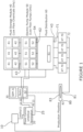
FIG. 1 is a block diagram of a first exemplary embodiment of the claimed invention describing the low flow system; -
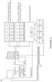
FIG. 2 is a block diagram of a second exemplary embodiment of the claimed invention describing the high flow startup chemical delivery system wherein a flowline is utilized to deliver startup chemicals at pressure and flow; -
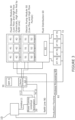
FIG. 3 is a block diagram of a third exemplary embodiment of the claimed invention describing the high flow system wherein a flowline is utilized to deliver startup chemicals at low pressure and flow to refill a series of subsea tanks and where a subsea high flow pump is utilized to deliver startup chemicals at pressure and flow; -
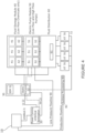
Fig. 4 is a block diagram of a fourth exemplary embodiment of the claimed invention describing the high flow system wherein a flowline is utilized to deliver startup chemicals at low pressure and flow to a subsea high flow pump wherein the chemical supply is boosted via the pump; and -
Fig. 5 is a block diagram of a further exemplary embodiment of the claimed invention. - In one aspect of the present disclosure there is provided a method as specified in
claim 1. In its various embodiments, the disclosed invention removes chemical delivery conduits from an umbilical, and in some instances eliminates all fluid conduits from the umbilical, and requires only electrical power and/or data delivery to a well site. - In embodiments, subsea fluid storage reservoirs are located on a seafloor adjacent to the well site for low fluid flow requirement chemicals necessary for the well. A subsea pumping system is typically included for boosting the chemical pressure from ambient to that required for injection into the production stream.
- In embodiments, low and high flow chemical delivery systems are segregated by use of subsea storage and pressure boosting for the low flow needs and a dedicated flowline from the host facility for the high flow needs. Subsea pressure boosting for the high fluid flow requirements can also be provided for allowing a low pressure flowline to be utilized and minimize cost. The modular approach offered by embodiments of the invention accommodates chemical storage and pumping systems expansion and modification.
- In embodiments, integrating the controls and monitoring of both the dual method fluid delivery system and the other subsea production system elements can simplify an umbilical system from a host facility.
- Referring to
Fig. 1 , in a first embodiment a modular subsea chemical injection system comprises one or more power andcommunication modules 20 operatively connected to one or more power andcommunications umbilicals 21, at least one power and communications umbilical 21 lacking a chemical delivery conduit; at least one power and communicationsumbilical terminator 22 operatively connected to umbilical 21; one or more power andcommunications modules 30; one or morefluid storage modules 40 operatively in communication withsubsea electronics module 31 andelectrical power distributor 32; one ormore pump modules 50 operatively in communication withsubsea electronics module 31 andelectrical power distributor 32; andfluid distribution unit 60. -
Host facility 10 may be operatively connected to power and communications umbilical 21. - In contemplated embodiments, subsea control module (SCM) 70 may be present, as more fully described below, where SCM 70 may further comprise
SCM fluid port 72. - Power and
communication terminator 20 comprises electrical power port 24 (not shown in the figures) which may comprise lowvoltage power outlet 22, highvoltage power outlet 23, or the like, or a combination thereof. Power and communicationsumbilical terminator 20 may further comprisedata communications port 25. IfSCM 70 is present, power andcommunications terminator 20 typically further comprises non-integral SCM power anddata communications port 25 operatively in communication withSCM 70. - At least one power and
communications modules 30 comprisessubsea electronics module 31 operatively in communication with power and communications umbilical terminatordata communications port 23 andelectrical power distributor 32 operatively in communication with power and communications umbilical terminator electrical power port 24.IfSCM 70 is present, power andcommunications module 30 may further comprise integral SCM power and data communications port 35 operatively in communication withSCM 70. -
Fluid storage modules 40 typically comprise a plurality offluid storage bays 41, eachfluid storage bay 41 adapted to selectively receive a corresponding plurality offluid storage tanks 42, and at least one fluid storagemodule fluid port 43 in fluid communication with one or more fluid storage tank 42.Not all fluid storage bays 41need to be populated at any given time. -
Pump module 50 typically comprises a plurality ofpump bays 51 adapted to selectively receive a corresponding plurality ofpumps 52, although not allpump bays 51 need to be populated at any given time. At least onepump 52 is in fluid communication with at least onefluid storage tank 42. In addition,pump module 50 further comprises one or more pumpmodule fluid ports 54 in fluid communication with at least onepump 52. In embodiments, one or more high flow fluid ports 53 may be present in fluid communication with at least onepump 52. -
Fluid distribution unit 60 typically comprises at least onedistribution fluid port 62 in fluid communication with at least one pumpmodule fluid port 54, at least one fluid distribution unit fluid supply port 63 in fluid communication withdistribution fluid port 62, andfluid metering valve 61 disposed intermediatedistribution fluid port 62 and fluid distribution unit fluid supply port 63. If one or more subsea control modules (SCM) 70 are present, each SCM 70 is typically in fluid communication with fluid distribution unit fluid supply port 63 such as viaport 71. In embodiments, eachSCM 70 is in fluid communication with a separate fluid distribution unit fluid supply port 63. - In contemplated embodiments,
subsea processing system 80 may be present and in fluid communication with fluid distribution unit fluid supply port 63 and/orSCM fluid port 72 such as via subsea processing systemfluid inlet port 81.Subsea processing system 80 may further comprisefluid delivery booster 83 which may be in fluid communication with subsea processing systemfluid inlet port 81. Ifhost facility 10 is present,subsea processing system 80 may further comprise at least one subsea processing systemfluid outlet port 82 in fluid communication withhost facility 10 and, iffluid delivery booster 83 is present, withfluid delivery booster 83. - Referring to
Fig. 2 , in a second embodiment a modular subsea chemical injection system comprises one or more power andcommunication modules 20 operatively connected to one or more power andcommunications umbilicals 21, at least one power and communications umbilical 21 lacking a chemical delivery conduit; at least one power and communicationsumbilical terminator 22 operatively connected to umbilical 21; one or more power andcommunications modules 30; one or morefluid storage modules 40 operatively in communication withsubsea electronics module 31 andelectrical power distributor 32; one ormore pump modules 50 operatively in communication withsubsea electronics module 31 andelectrical power distributor 32; andfluid distribution unit 60. -
Host facility 10 may be operatively connected to power and communications umbilical 21. - In contemplated embodiments, subsea control module (SCM) 70 may be present, as more fully described below, where SCM 70 may further comprise
SCM fluid port 72. - Power and
communication terminator 20 comprises electrical power port 24 (not shown in the figures) which may comprise lowvoltage power outlet 22, highvoltage power outlet 23, or the like, or a combination thereof. Power and communicationsumbilical terminator 20 may further comprisedata communications port 25. IfSCM 70 is present, power andcommunications terminator 20 typically further comprises non-integral SCM power anddata communications port 25 operatively in communication withSCM 70. - At least one power and
communications modules 30 comprisessubsea electronics module 31 operatively in communication with power and communications umbilical terminatordata communications port 23 andelectrical power distributor 32 operatively in communication with power and communications umbilical terminator electrical power port 24.IfSCM 70 is present, power andcommunications module 30 may further comprise integral SCM power and data communications port 35 operatively in communication withSCM 70. -
Fluid storage modules 40 typically comprise a plurality offluid storage bays 41, eachfluid storage bay 41 adapted to selectively receive a corresponding plurality offluid storage tanks 42, and at least one fluid storagemodule fluid port 43 in fluid communication with one or more fluid storage tank 42.Not all fluid storage bays 41need to be populated at any given time. -
Pump module 50 typically comprises a plurality ofpump bays 51 adapted to selectively receive a corresponding plurality ofpumps 52, although not allpump bays 51 need to be populated at any given time. At least onepump 52 is in fluid communication with at least onefluid storage tank 42. In addition,pump module 50 further comprises one or more pumpmodule fluid ports 54 in fluid communication with at least onepump 52. In embodiments, one or more high flow fluid ports 53 may be present in fluid communication with at least onepump 52. -
Fluid distribution unit 60 typically comprises at least onedistribution fluid port 62 in fluid communication with at least one pumpmodule fluid port 54, at least one fluid distribution unit fluid supply port 63 in fluid communication withdistribution fluid port 62, andfluid metering valve 61 disposed intermediatedistribution fluid port 62 and fluid distribution unit fluid supply port 63. If one or more subsea control modules (SCM) 70 are present, eachSCM 70 is typically in fluid communication with fluid distribution unit fluid supply port 63 such as viaport 71. In embodiments, eachSCM 70 is in fluid communication with a separate fluid distribution unit fluid supply port 63. - In contemplated embodiments,
subsea processing system 80 may be present and in fluid communication with fluid distribution unit fluid supply port 63 and/orSCM fluid port 72 such as via subsea processing systemfluid inlet port 81.Subsea processing system 80 may further comprisefluid delivery booster 83 which may be in fluid communication with subsea processing systemfluid inlet port 81. Ifhost facility 10 is present,subsea processing system 80 may further comprise at least one subsea processing systemfluid outlet port 82 in fluid communication withhost facility 10 and, iffluid delivery booster 83 is present, withfluid delivery booster 83. - In contemplated embodiments, a single standalone flowline 90 (composite, carbon steel, stainless) is connected from the
surface host 10 to the subseafluid distribution unit 60. Chemical startup fluid is pressurized via thesurface host 10 and delivered at the required flow rate to thefluid distribution unit 60. - Referring to
Fig. 3 , in a third embodiment a modular subsea chemical injection system comprises one or more power andcommunication modules 20 operatively connected to one or more power and communications umbilicals 21, at least one power and communications umbilical 21 lacking a chemical delivery conduit; at least one power and communicationsumbilical terminator 22 operatively connected to umbilical 21; one or more power andcommunications modules 30; one or morefluid storage modules 40 operatively in communication withsubsea electronics module 31 andelectrical power distributor 32; one ormore pump modules 50 operatively in communication withsubsea electronics module 31 andelectrical power distributor 32; andfluid distribution unit 60. -
Host facility 10 may be operatively connected to power and communications umbilical 21. - In contemplated embodiments, subsea control module (SCM) 70 may be present, as more fully described below, where
SCM 70 may further compriseSCM fluid port 72. - Power and
communication terminator 20 comprises electrical power port 24 (not shown in the figures) which may comprise lowvoltage power outlet 22, highvoltage power outlet 23, or the like, or a combination thereof. Power and communicationsumbilical terminator 20 may further comprisedata communications port 25. IfSCM 70 is present, power andcommunications terminator 20 typically further comprises non-integral SCM power anddata communications port 25 operatively in communication withSCM 70. - At least one power and
communications modules 30 comprisessubsea electronics module 31 operatively in communication with power and communications umbilical terminatordata communications port 23 andelectrical power distributor 32 operatively in communication with power and communications umbilical terminator electrical power port 24.IfSCM 70 is present, power andcommunications module 30 may further comprise integral SCM power and data communications port 35 operatively in communication withSCM 70. -
Fluid storage modules 40 typically comprise a plurality offluid storage bays 41, eachfluid storage bay 41 adapted to selectively receive a corresponding plurality offluid storage tanks 42, and at least one fluid storagemodule fluid port 43 in fluid communication with one or more fluid storage tank 42.Not all fluid storage bays 41need to be populated at any given time. -
Pump module 50 typically comprises a plurality ofpump bays 51 adapted to selectively receive a corresponding plurality ofpumps 52, although not all pumpbays 51 need to be populated at any given time. At least onepump 52 is in fluid communication with at least onefluid storage tank 42. In addition,pump module 50 further comprises one or more pumpmodule fluid ports 54 in fluid communication with at least onepump 52. In embodiments, one or more high flow fluid ports 53 may be present in fluid communication with at least onepump 52. -
Fluid distribution unit 60 typically comprises at least onedistribution fluid port 62 in fluid communication with at least one pumpmodule fluid port 54, at least one fluid distribution unit fluid supply port 63 in fluid communication withdistribution fluid port 62, andfluid metering valve 61 disposed intermediatedistribution fluid port 62 and fluid distribution unit fluid supply port 63. If one or more subsea control modules (SCM) 70 are present, eachSCM 70 is typically in fluid communication with fluid distribution unit fluid supply port 63 such as viaport 71. In embodiments, eachSCM 70 is in fluid communication with a separate fluid distribution unit fluid supply port 63. - In contemplated embodiments,
subsea processing system 80 may be present and in fluid communication with fluid distribution unit fluid supply port 63 and/orSCM fluid port 72 such as via subsea processing systemfluid inlet port 81.Subsea processing system 80 may further comprisefluid delivery booster 83 which may be in fluid communication with subsea processing systemfluid inlet port 81. Ifhost facility 10 is present,subsea processing system 80 may further comprise at least one subsea processing systemfluid outlet port 82 in fluid communication withhost facility 10 and, iffluid delivery booster 83 is present, withfluid delivery booster 83. - In contemplated embodiments, a single standalone flowline 90 (composite, carbon steel, stainless) is connected from the
surface host 10 tofluid storage module 40. -
Single flowline 90 is comprised of low pressure capability designed to aid in refilling fluid storage tanks housing startup chemicals. - Referring to
Fig. 4 , in a third embodiment a modular subsea chemical injection system comprises one or more power andcommunication modules 20 operatively connected to one or more power and communications umbilicals 21, at least one power and communications umbilical 21 lacking a chemical delivery conduit; at least one power and communicationsumbilical terminator 22 operatively connected to umbilical 21; one or more power andcommunications modules 30; one or morefluid storage modules 40 operatively in communication withsubsea electronics module 31 andelectrical power distributor 32; one ormore pump modules 50 operatively in communication withsubsea electronics module 31 andelectrical power distributor 32; andfluid distribution unit 60. -
Host facility 10 may be operatively connected to power and communications umbilical 21. - In contemplated embodiments, subsea control module (SCM) 70 may be present, as more fully described below, where
SCM 70 may further compriseSCM fluid port 72. - Power and
communication terminator 20 comprises electrical power port 24 (not shown in the figures) which may comprise lowvoltage power outlet 22, highvoltage power outlet 23, or the like, or a combination thereof. Power and communicationsumbilical terminator 20 may further comprisedata communications port 25. IfSCM 70 is present, power andcommunications terminator 20 typically further comprises non-integral SCM power anddata communications port 25 operatively in communication withSCM 70. - At least one power and
communications modules 30 comprisessubsea electronics module 31 operatively in communication with power and communications umbilical terminatordata communications port 23 andelectrical power distributor 32 operatively in communication with power and communications umbilical terminator electrical power port 24. IfSCM 70 is present, power andcommunications module 30 may further comprise integral SCM power and data communications port 35 operatively in communication withSCM 70. -
Fluid storage modules 40 typically comprise a plurality offluid storage bays 41, where eachfluid storage bay 41 is adapted to selectively receive a corresponding plurality offluid storage tanks 42, and at least one fluid storagemodule fluid port 43 in fluid communication with one or morefluid storage tank 42. Not allfluid storage bays 41 need to be populated at any given time. -
Pump module 50 typically comprises a plurality ofpump bays 51 adapted to selectively receive a corresponding plurality ofpumps 52, although not all pumpbays 51 need to be populated at any given time. At least onepump 52 is in fluid communication with at least onefluid storage tank 42. In addition,pump module 50 further comprises one or more pumpmodule fluid ports 54 in fluid communication with at least onepump 52. In embodiments, one or more high flow fluid ports 53 may be present in fluid communication with at least onepump 52. -
Fluid distribution unit 60 typically comprises at least onedistribution fluid port 62 in fluid communication with at least one pumpmodule fluid port 54, at least one fluid distribution unit fluid supply port 63 in fluid communication withdistribution fluid port 62, andfluid metering valve 61 disposed intermediatedistribution fluid port 62 and fluid distribution unit fluid supply port 63. If one or more subsea control modules (SCM) 70 are present, eachSCM 70 is typically in fluid communication with fluid distribution unit fluid supply port 63 such as viaport 71. In embodiments, eachSCM 70 is in fluid communication with a separate fluid distribution unit fluid supply port 63. - In contemplated embodiments,
subsea processing system 80 may be present and in fluid communication with fluid distribution unit fluid supply port 63 and/orSCM fluid port 72 such as via subsea processing systemfluid inlet port 81.Subsea processing system 80 may further comprisefluid delivery booster 83 which may be in fluid communication with subsea processing systemfluid inlet port 81. Ifhost facility 10 is present,subsea processing system 80 may further comprise at least one subsea processing systemfluid outlet port 82 in fluid communication withhost facility 10 and, iffluid delivery booster 83 is present, withfluid delivery booster 83. - In contemplated embodiments, a single standalone flowline 90 (which can be composite, carbon steel, stainless, or the like, or a combination thereof) is connected from the
surface host 10 to theelectric pump module 50. -
Single flowline 90 is comprised of low pressure capability designed to deliver required chemical startup flowrates higher than required but at low pressure. - Single or
multiple pumps 52 take the low pressure supply from theflowline 90 and boost the to the required injection pressure. - Startup chemicals are delivered via the
pumps 52 to theport 62 to thefluid distribution unit 60 to service the wells during startup and shutdown. - Each
pump 52 is typically configured to be self-contained and isolatable from the remaining pumps 52 of the predetermined set ofindividual pumps 52 and to be selectively removable from thebays 51. Moreover, each pump 52 typically comprisesstorage tank 42, lowflow fluid pump 52 in fluid communication withstorage tank 42, and fluid pump controller in communication with umbilical 21. Each ofstorage tank 42, lowflow fluid pump 52, and fluid pump controller 1103 may be scalable.Storage tank 42 may comprise a multi-fluid storage tank. In such configurations,multi-fluid storage tank 42 may further comprise a multi-fluid storage tank which is refillable or replacable subsea. - One or
more pumps 52 may further comprise a pump designed to deliver fluid to multiple wells distributed via subsea manifold . - Each
pump 52 is typically configured to be selectively removable fromhousing 42 such as via a remotely operated vehicle (ROV), an autonomous underwater vehicle (AUV), a crane assist, or the like, or a combination thereof. - Leak detector 1110 may be integrated within
fluid storage units 42. In addition, leak detector 1110 may comprise ROV compatible fluid sampler and tester 1111. - In contemplated embodiments, at least one
pump module 50 may further comprise chemical delivery system 1120 which is adapted to provide one or more arrangements of electrically or battery powered positive displacement pumps 1121 which may be driven by a single motor 1122, e.g. multiple pumps 1121 coupled to a single motor 1122 to achieve desired flow rate. In other embodiments, multiple pumps 1121 may be coupled to a single motor adjustable such as via stroke to achieve multiple flow rates. - Level indication measurer 1123 may be present for fluid stored in an
fluid storage units 42. - In embodiments, a chemical filter may be present and configured to minimize risk to pump and metering valve failure rates. Chemical filter may comprise an ROV replaceable chemical filter in conjunction with or independent of delivery methods.
-
Pump module 52 typically comprises pump module housing comprising a plurality of pump receivers pump fluid inlet in fluid communication with modular subsea chemical injection skid pump fluid outlet a predetermined set of low flow fluid pumps, each low flow fluid pump configured to be received into a pump receiver of the plurality of pump receivers ; and fluid pump controller in communication with umbilical signal conduit. Each low flow fluid pump is typically in fluid communication with pump fluid inlet and pump fluid outlet. High flow chemical flowline may be present and in fluid communication with pump module. - Subsea fluid processor typically comprises subsea electronics controller and electrical power distributor . Subsea fluid processor may further comprise subsea fluid processor, subsea fluid pressure booster, and/or chemical metering valve. Where present, one chemical metering valve may be present for each low flow fluid pump of the predetermined set of low flow fluid pumps.
- Power and communications umbilical terminator is typically operatively connected to fluid distributor and comprises host umbilical connector port .
- Power and communication foundation may comprise subsea electronics controller and electrical power distributor for
- In further contemplated embodiments, referring generally to
Fig. 5 a system for delivering fluids subsea comprisesumbilical termination assembly 200 designed to break out power cable or electrical umbilical into motive power source, communication pathway which may be bidirectional to provide both feedback to surface location and/or to receive commands/data from surface location, and low voltage power source to supply low voltage to the field. - Modular electric/
power distribution module 300 designed to be retrievable and comprisessubsea electronics housing 301. In embodiments, electric/power distribution module 300 comprisessubsea transformer 310 to step down voltage to usable motive power levels for and distribute electrical signals to the various other modules. -
Switchgear 310 is housed insubsea electronics housing 301 and configured for control and protection of electrical components. - Distribution panels/
equipment 311 is housed insubsea electronics housing 301 and usable to deliver signals and power to other various modules. -
Mudmat 302 is sized to contain and support numerous electrical components.Mudmat 302 is typically sized to contain and support numerous pump modules and may comprise additional slots for expansion if needed. -
Subsea electronics module 300 is designed to control components and data exchange throughout predetermined components of the system for delivering fluids subsea and typically comprises controls for automatic fail safe state should a loss of power, communications, and/or controls occur. It also typically receives and collects data/information from all individual modules within the system such as system pressure, valve position, cycle counter, RPM, flow rate, linear position, stroke rate, chemical leak detect, water detection, ground fault monitoring, voltage, and/or current. In embodiments,subsea electronics module 31 receives commands such as via a topside communication link and relays controls and commands to appropriate modules. In certain embodiments the system for delivering fluids subsea may comprise one or more redundant and/or secondary communication links. - Modular
fluid storage module 400 is configured to contain a variety of fluids utilized in subsea production activities and comprisesframe 410 designed to be delivered and retrieved subsea. -
Frame 410 may be locked in place via locking pins 411. One or more indicators 412 may be present to aid in confirm positioning of modularfluid storage module 400.Frame 410 typically comprisesROV interface 420 which comprises one or moresubsea interconnects 421 for a predetermined set of connections, by way of example and not limitation comprising low voltage power, data communications, hydraulic connections for suction and discharge, stab plate and connector connectors, instrument and visual indicators designed to relay information topside about the condition of the system, leak detection, and/or level indication. In addition,module 430, which comprises control valves, may be used to isolate the system for delivering fluids subsea via topside communication or manually via an ROV. - A predetermined number of storage modules 402 are disposed within
frame 410 and utilized for storage of low flow fluids. Overpressure relief device 413 may be present and disposed within a hydraulic circuit and usable to provide system relief due to under pressure within the hydraulic circuit. - One or more
chemical tanks 401 may be removably disposed in storage modules 402, each of which may comprise a bladder is designed to be a form of secondary containment -
Electric pump module 500 is utilized for delivery of flow assurance chemicals via subsea stored chemicals or boosting for high flow line, and comprises one ormore pumps 501, which may comprise a positive displacement pump modified for subsea use, removably disposed inpump storage 500.Pumps 501 are typically disposed withinframe 510 and sized to distribute low flow, high pressure inhibitor type chemicals to a multitude of wells or sized to deliver low flow, high pressure inhibitor type chemicals to a single well. In certain embodiments, a single motor drives a single pump or a series of pump. Pump 501 may be rated for metering or dosing. Flow rate can be adjusted via a VFD or a metering valve. As with other modules,electric pump module 500 may comprise an adjustable device for the regulation of system pressure, one or more devices for system relief of over pressure within the hydraulic circuit, and/or one or more a devices for system relief due to under pressure within the hydraulic circuit. - Components of
electric pump module 500 are typically housed inframe 510 which is designed to be delivered and retrieved subsea.Frame 510 may be locked in place via locking pins and comprise indicator to aid in confirming position.Frame 510 may further comprise an ROV interface with subsea interconnects for low voltage power, data communciations, motive power, hydraulic connections for suction and discharge, and/or stab plate and connector connections.Electric pump module 500 components may be protected via subsea compensation and may further comprise one or more control valves which can isolate system via topside communication or manually via an ROV. - In the operation of exemplary embodiments, the overall cost from both a manufacturing and installation perspective of fluids subsea may be minimized by using one or more of the disclosed systems and providing umbilical 21 that lacks a chemical delivery conduit; locating a subsea fluid storage reservoir such as 40 on a seafloor adjacent to a well site, where subsea
fluid storage reservoir 40 is configured to provide low flow requirement fluids necessary for the well; and segregating low and high flow chemical delivery systems by use of subsea storage and pressure boosting for the low flow needs and a dedicated flowline from the host facility for the high flow needs. - In embodiments, all fluid conduits may be eliminated from umbilical 21 and only electrical power needs to be delivered to the well site. In those embodiments with boosters, fluid pressure may be boosted subsea from the subsea storage reservoir for high flow chemical requirements such as boosting the chemical fluid pressure from ambient to that required for injection into the production stream. In certain embodiments, a low pressure flowline may be utilized to minimize cost.
- As used herein, a "host" can be defined as a floating deepwater production facility, a permanently fixed structure, an unmanned floating control buoy, or the like.
- The invention is defined by the features specified in the appended claims.
Claims (6)
- A method to minimize the overall cost from both a manufacturing and installation perspective for modular subsea chemical injection system comprising a power and communications module to be operatively connected to an umbilical (21) that lacks a chemical delivery conduit, a power and communications umbilical terminator (20) to be operatively connected to the umbilical where the power and communications umbilical terminator comprises a data communications port and an electrical power port, a power and communications module (30) comprising a subsea electronics module operatively in communication with the power and communications umbilical terminator data communications port and further comprising an electrical power distributor (32) operatively in communication with the power and communications umbilical terminator electrical power port, a fluid storage module (40) operatively in communication with the subsea electronics module and the electrical power distributor and comprising a plurality of fluid storage bays (41) adapted to selectively receive a corresponding plurality of fluid storage units (42) where the fluid storage units (42) comprise at least one high flow fluid storage unit and at least one low flow fluid storage unit, a pump module (50) operatively in communication with the subsea electronics module and the electrical power distributor and the fluid storage module and comprising a plurality of pump bays (51) adapted to selectively receive a corresponding plurality of pumps (52), and a fluid distribution unit (60) in fluid communication with a pump module fluid port (54), the method comprising:a. providing an umbilical (21) that lacks a chemical delivery conduit;b. operatively connecting the umbilical to the power and communications module (30) and the power and communications umbilical terminator (20);c. disposing the fluid storage module (40) on a seafloor adjacent to a well site, the fluid storage module configured to selectively provide low fluid flow requirement fluids and high fluid flow requirement fluids for an adjacent well disposed proximate the well site; andd. segregating low and high flow chemical delivery of fluids by populating a first pump bay (51) of the plurality of pump bays (51) with a high fluid flow pump (52) and placing the high fluid flow pump (52) into fluid communication with a high fluid flow fluid storage tank (42) and by populating a second pump bay (51) of the plurality of pump bays (51) with a low fluid flow pump (52) and placing the low fluid flow pump (52) into fluid communication with a low fluid flow fluid storage tank (42); ande. selectively providing low and high flow fluid delivery by use of subsea storage and pressure boosting for low flow fluid needs and high flow fluid needs by using one of the high fluid flow pumps (52) to provide high fluid flow and/or one of the low fluid flow pumps (52) to provide low fluid flow.
- The method to minimize the overall cost from both a manufacturing and installation perspective of Claim 1, further comprising:a. providing a dedicated flowline from a host facility associated with the well; andb. using the dedicated flowline to provide high flow fluid to the well for high flow needs.
- The method to minimize the overall cost from both a manufacturing and installation perspective of Claim 1, further comprising using a pump from the high fluid flow and low fluid flow pumps to boost fluid pressure subsea from the fluid storage module (40) for high flow chemical requirements; and further comprising allowing a low pressure flowline to be utilized for supplying fluid whose fluid pressure is to be boosted by the pump.
- The method to minimize the overall cost from both a manufacturing and installation perspective of Claim 1, further comprising using a pump from the high fluid flow pumps to boost fluid pressure subsea from the fluid storage module for high flow chemical requirements and, further comprising allowing a low pressure flowline to be utilized for supplying fluid whose fluid pressure is to be boosted by the pump.
- The method to minimize the overall cost from both a manufacturing and installation perspective of Claim 1, further comprising using a pump from the low fluid flow pumps to boost fluid pressure subsea from the fluid storage module for high flow chemical requirements and, further comprising allowing a low pressure flowline to be utilized for supplying fluid whose fluid pressure is to be boosted by the pump
- The method to minimize the overall cost from both a manufacturing and installation perspective of Claim 1, further comprising boosting fluid flow pressure from ambient to that required for injection into a production stream.
Priority Applications (2)
| Application Number | Priority Date | Filing Date | Title |
|---|---|---|---|
| EP20195582.0A EP3783191B1 (en) | 2016-03-30 | 2017-03-31 | Dual method subsea chemical delivery and pressure boosting |
| EP20195576.2A EP3805464B1 (en) | 2016-03-30 | 2017-03-31 | Dual method subsea chemical delivery and pressure boosting |
Applications Claiming Priority (2)
| Application Number | Priority Date | Filing Date | Title |
|---|---|---|---|
| US201662315417P | 2016-03-30 | 2016-03-30 | |
| PCT/US2017/025221 WO2017173192A1 (en) | 2016-03-30 | 2017-03-31 | Dual method subsea chemical delivery and pressure boosting |
Related Child Applications (4)
| Application Number | Title | Priority Date | Filing Date |
|---|---|---|---|
| EP20195576.2A Division-Into EP3805464B1 (en) | 2016-03-30 | 2017-03-31 | Dual method subsea chemical delivery and pressure boosting |
| EP20195576.2A Division EP3805464B1 (en) | 2016-03-30 | 2017-03-31 | Dual method subsea chemical delivery and pressure boosting |
| EP20195582.0A Division-Into EP3783191B1 (en) | 2016-03-30 | 2017-03-31 | Dual method subsea chemical delivery and pressure boosting |
| EP20195582.0A Division EP3783191B1 (en) | 2016-03-30 | 2017-03-31 | Dual method subsea chemical delivery and pressure boosting |
Publications (3)
| Publication Number | Publication Date |
|---|---|
| EP3500704A1 EP3500704A1 (en) | 2019-06-26 |
| EP3500704A4 EP3500704A4 (en) | 2020-03-25 |
| EP3500704B1 true EP3500704B1 (en) | 2024-11-13 |
Family
ID=59960762
Family Applications (3)
| Application Number | Title | Priority Date | Filing Date |
|---|---|---|---|
| EP20195582.0A Active EP3783191B1 (en) | 2016-03-30 | 2017-03-31 | Dual method subsea chemical delivery and pressure boosting |
| EP17776730.8A Active EP3500704B1 (en) | 2016-03-30 | 2017-03-31 | Dual method subsea chemical delivery and pressure boosting |
| EP20195576.2A Active EP3805464B1 (en) | 2016-03-30 | 2017-03-31 | Dual method subsea chemical delivery and pressure boosting |
Family Applications Before (1)
| Application Number | Title | Priority Date | Filing Date |
|---|---|---|---|
| EP20195582.0A Active EP3783191B1 (en) | 2016-03-30 | 2017-03-31 | Dual method subsea chemical delivery and pressure boosting |
Family Applications After (1)
| Application Number | Title | Priority Date | Filing Date |
|---|---|---|---|
| EP20195576.2A Active EP3805464B1 (en) | 2016-03-30 | 2017-03-31 | Dual method subsea chemical delivery and pressure boosting |
Country Status (3)
| Country | Link |
|---|---|
| US (1) | US9915129B2 (en) |
| EP (3) | EP3783191B1 (en) |
| WO (1) | WO2017173192A1 (en) |
Families Citing this family (7)
| Publication number | Priority date | Publication date | Assignee | Title |
|---|---|---|---|---|
| US11421673B2 (en) | 2016-09-02 | 2022-08-23 | Halliburton Energy Services, Inc. | Hybrid drive systems for well stimulation operations |
| WO2019164511A1 (en) * | 2018-02-23 | 2019-08-29 | Halliburton Energy Services, Inc. | Storage, transport, and delivery of well treatments |
| CN111101477B (en) * | 2019-12-30 | 2020-10-30 | 长江大学 | Method for determining flow of low-grade water during supplement actual measurement of data-free design basin |
| US11053776B1 (en) * | 2020-03-23 | 2021-07-06 | Smart Subsea, Llc | Subsea chemical injection metering valve communications module and system for injecting chemicals into a subsea structure |
| CN113863901B (en) * | 2021-08-10 | 2023-11-28 | 海洋石油工程股份有限公司 | Method for constructing functional loop of underwater high-integrity pressure protection device |
| US12498288B2 (en) * | 2022-03-31 | 2025-12-16 | Lenovo Global Technology (United States) Inc. | System and method for detecting coolant leaks in a server system |
| US12540607B2 (en) | 2023-06-23 | 2026-02-03 | Halliburton Energy Services, Inc. | Hybrid drive and distributed power systems for well stimulation operations |
Citations (4)
| Publication number | Priority date | Publication date | Assignee | Title |
|---|---|---|---|---|
| US20110114329A1 (en) | 2009-11-18 | 2011-05-19 | Chevron U.S.A. Inc. | Apparatus and method for providing a controllable supply of fluid to subsea well equipment |
| US20120175125A1 (en) | 2010-11-15 | 2012-07-12 | Oceaneering International, Inc. | Subsea pod pump |
| WO2015092331A1 (en) | 2013-12-19 | 2015-06-25 | Total Sa | Method for injecting fluids into an underwater facility |
| WO2015200661A1 (en) | 2014-06-26 | 2015-12-30 | Cameron International Corporation | Subsea on-site chemical injection management system |
Family Cites Families (13)
| Publication number | Priority date | Publication date | Assignee | Title |
|---|---|---|---|---|
| US3643741A (en) * | 1970-02-03 | 1972-02-22 | Salvatore W Miranda | Sealing of underwater fissures |
| NO20031569A (en) * | 2003-04-08 | 2004-06-21 | Soerco As | Method and apparatus for treating water to an injection well |
| CA2583270A1 (en) * | 2004-10-06 | 2006-04-13 | Oceaneering International, Inc. | Subsea fluid delivery system and method |
| GB0700114D0 (en) * | 2007-01-04 | 2007-02-14 | Qinetiq Ltd | Subsea chemical injection system and pumps therefor |
| GB2482466B (en) * | 2009-05-04 | 2014-02-12 | Cameron Int Corp | System and method of providing high pressure fluid injection with metering using low pressure supply lines |
| SG175720A1 (en) * | 2009-06-25 | 2011-12-29 | Cameron Int Corp | Sampling skid for subsea wells |
| US9034182B2 (en) * | 2010-08-24 | 2015-05-19 | Shell Oil Company | Deepwater dispersion system and method of using same background |
| AU2011316751A1 (en) * | 2010-10-12 | 2013-05-02 | Bp Corporation North America Inc. | Subsea autonomous dispersant injection system and methods |
| NO331478B1 (en) * | 2010-12-21 | 2012-01-16 | Seabox As | Technical system, method and applications for dosing at least one liquid treatment agent in injection water to an injection well |
| NO333264B1 (en) * | 2011-04-18 | 2013-04-22 | Siemens Ag | Pump system, method and applications for transporting injection water to an underwater injection well |
| WO2012148993A2 (en) * | 2011-04-28 | 2012-11-01 | Bp Corporation North America, Inc. | Subsea dispersant injection systems and methods |
| GB2521826B (en) * | 2013-12-18 | 2017-11-08 | Ge Oil & Gas Uk Ltd | Multiple chemical supply line |
| US10137484B2 (en) * | 2015-07-16 | 2018-11-27 | Exxonmobil Upstream Research Company | Methods and systems for passivation of remote systems by chemical displacement through pre-charged conduits |
-
2017
- 2017-03-30 US US15/475,126 patent/US9915129B2/en active Active
- 2017-03-31 WO PCT/US2017/025221 patent/WO2017173192A1/en not_active Ceased
- 2017-03-31 EP EP20195582.0A patent/EP3783191B1/en active Active
- 2017-03-31 EP EP17776730.8A patent/EP3500704B1/en active Active
- 2017-03-31 EP EP20195576.2A patent/EP3805464B1/en active Active
Patent Citations (4)
| Publication number | Priority date | Publication date | Assignee | Title |
|---|---|---|---|---|
| US20110114329A1 (en) | 2009-11-18 | 2011-05-19 | Chevron U.S.A. Inc. | Apparatus and method for providing a controllable supply of fluid to subsea well equipment |
| US20120175125A1 (en) | 2010-11-15 | 2012-07-12 | Oceaneering International, Inc. | Subsea pod pump |
| WO2015092331A1 (en) | 2013-12-19 | 2015-06-25 | Total Sa | Method for injecting fluids into an underwater facility |
| WO2015200661A1 (en) | 2014-06-26 | 2015-12-30 | Cameron International Corporation | Subsea on-site chemical injection management system |
Non-Patent Citations (8)
| Title |
|---|
| D10 - ARTICLE "SUBSEA STATIONS COULD REDUCE COST, LOADS OF LONG-DISTANCE UMBILICALS" - GABRIEL BEAUDONNET, DAVID CHILLOUX, LUC RIVIÈR, GUILLAUME DELAETER - DORIS ENGINEERING & TOTAL – OFFSHORE, DISCLOSED ON 08.08.2013 |
| D11 - OPERATOR PARTICIPATION MCEDD MADRID 08-10.04.2014 |
| D12 - Affidavit of Mr Vincent Peyrony |
| D7 - BROCHURE "MCE DEEPWATER DEVELOPMENT 2014- SHOW PROGRAM", DISCLOSED ON 08- 10.10.2014 |
| D8 - BROCHURE "MCE DEEPWATER DEVELOPMENT 2015– TECHNICAL PROGRAM", DISCLOSED ON 24- 26.03.2015, EXCEL , LONDON |
| D9 - SLIDESHOW "SUBSEA STATION FOR CHEMICAL STORAGE AND INJECTION" - GABRIEL BEAUDONNET & VINCENT PEYRONY - DORIS ENGINEERING & TOTAL – SUBSEA FORUM RIO 2014, DISCLOSED ON 26- 28.05.2014 |
| GABRIEL BEAUDONNET, CHILLOUX DAVID, RIVIÈRE LUC, DELAËTER GUILLAUME : "Subsea Station for Chemical Storage and Injection", DEEP OFFSHORE TECHNOLOGY CONFERENCE, - 29 November 2012 (2012-11-29), XP055304627 |
| VINCENT PEYRONY, BEAUDONNET GABRIEL: "Subsea Station for Chemical Storage and Injection: 2 Case Studies", XP055304628, Retrieved from the Internet <URL:http://mcedd.com/wp-content/uploads/Gabriel Beaudonnet & Vincent Peyrony - Doris & Total.pdf> [retrieved on 20160922] |
Also Published As
| Publication number | Publication date |
|---|---|
| EP3500704A1 (en) | 2019-06-26 |
| WO2017173192A1 (en) | 2017-10-05 |
| EP3805464B1 (en) | 2025-09-03 |
| EP3783191A1 (en) | 2021-02-24 |
| US20170284173A1 (en) | 2017-10-05 |
| EP3805464A1 (en) | 2021-04-14 |
| US9915129B2 (en) | 2018-03-13 |
| EP3783191B1 (en) | 2025-07-09 |
| EP3500704A4 (en) | 2020-03-25 |
Similar Documents
| Publication | Publication Date | Title |
|---|---|---|
| EP3500704B1 (en) | Dual method subsea chemical delivery and pressure boosting | |
| US6640901B1 (en) | Retrievable module and operating method suitable for a seabed processing system | |
| US8955595B2 (en) | Apparatus and method for providing a controllable supply of fluid to subsea well equipment | |
| US8500419B2 (en) | Subsea pumping system with interchangable pumping units | |
| US8083501B2 (en) | Subsea pumping system including a skid with wet matable electrical and hydraulic connections | |
| CN107002479A (en) | High pressure subsea blowout preventer system | |
| US9309750B2 (en) | Subsea on-site chemical injection management system | |
| BRPI0903198A2 (en) | pumping system for use in a subsea location, system for use in a subsea pumping application, method for pumping fluid in a subsea location, and method | |
| US20200199960A1 (en) | Reliability assessable systems for actuating hydraulically actuated devices and related methods | |
| NO20120468A1 (en) | Integrated production manifold and multiphase pump station | |
| US20050178556A1 (en) | Subsea hydrocarbon production system | |
| CN103097651A (en) | Combined barrier and lubrication fluids pressure regulation system and unit for a subsea motor and pump module | |
| CN103477024B (en) | The method and apparatus extending at least life-span of production tree or pipeline | |
| EP4146908B1 (en) | Subsea autonomous chemical injection system | |
| US9033053B2 (en) | Method and device for extending lifetime of a wellhead |
Legal Events
| Date | Code | Title | Description |
|---|---|---|---|
| STAA | Information on the status of an ep patent application or granted ep patent |
Free format text: STATUS: THE INTERNATIONAL PUBLICATION HAS BEEN MADE |
|
| PUAI | Public reference made under article 153(3) epc to a published international application that has entered the european phase |
Free format text: ORIGINAL CODE: 0009012 |
|
| STAA | Information on the status of an ep patent application or granted ep patent |
Free format text: STATUS: REQUEST FOR EXAMINATION WAS MADE |
|
| 17P | Request for examination filed |
Effective date: 20180926 |
|
| AK | Designated contracting states |
Kind code of ref document: A1 Designated state(s): AL AT BE BG CH CY CZ DE DK EE ES FI FR GB GR HR HU IE IS IT LI LT LU LV MC MK MT NL NO PL PT RO RS SE SI SK SM TR |
|
| AX | Request for extension of the european patent |
Extension state: BA ME |
|
| DAV | Request for validation of the european patent (deleted) | ||
| DAX | Request for extension of the european patent (deleted) | ||
| RIC1 | Information provided on ipc code assigned before grant |
Ipc: B65D 88/78 20060101ALI20191008BHEP Ipc: B63G 8/00 20060101ALI20191008BHEP Ipc: E02B 15/08 20060101ALI20191008BHEP Ipc: E21B 37/06 20060101ALI20191008BHEP Ipc: E02B 15/04 20060101AFI20191008BHEP Ipc: E21B 33/076 20060101ALI20191008BHEP Ipc: E21B 43/01 20060101ALI20191008BHEP |
|
| A4 | Supplementary search report drawn up and despatched |
Effective date: 20200225 |
|
| RIC1 | Information provided on ipc code assigned before grant |
Ipc: E02B 15/04 20060101AFI20200219BHEP Ipc: E02B 15/08 20060101ALI20200219BHEP Ipc: E21B 43/01 20060101ALI20200219BHEP Ipc: B63G 8/00 20060101ALI20200219BHEP Ipc: E21B 33/076 20060101ALI20200219BHEP Ipc: E21B 37/06 20060101ALI20200219BHEP Ipc: B65D 88/78 20060101ALI20200219BHEP |
|
| STAA | Information on the status of an ep patent application or granted ep patent |
Free format text: STATUS: EXAMINATION IS IN PROGRESS |
|
| 17Q | First examination report despatched |
Effective date: 20201123 |
|
| P01 | Opt-out of the competence of the unified patent court (upc) registered |
Effective date: 20230526 |
|
| REG | Reference to a national code |
Ref legal event code: R079 Free format text: PREVIOUS MAIN CLASS: E02B0015040000 Ref country code: DE Ref legal event code: R079 Ref document number: 602017086108 Country of ref document: DE Free format text: PREVIOUS MAIN CLASS: E02B0015040000 Ipc: E21B0041020000 |
|
| GRAP | Despatch of communication of intention to grant a patent |
Free format text: ORIGINAL CODE: EPIDOSNIGR1 |
|
| STAA | Information on the status of an ep patent application or granted ep patent |
Free format text: STATUS: GRANT OF PATENT IS INTENDED |
|
| RIC1 | Information provided on ipc code assigned before grant |
Ipc: E21B 37/06 20060101ALI20240229BHEP Ipc: E21B 41/02 20060101AFI20240229BHEP |
|
| INTG | Intention to grant announced |
Effective date: 20240319 |
|
| GRAJ | Information related to disapproval of communication of intention to grant by the applicant or resumption of examination proceedings by the epo deleted |
Free format text: ORIGINAL CODE: EPIDOSDIGR1 |
|
| STAA | Information on the status of an ep patent application or granted ep patent |
Free format text: STATUS: EXAMINATION IS IN PROGRESS |
|
| INTC | Intention to grant announced (deleted) | ||
| GRAP | Despatch of communication of intention to grant a patent |
Free format text: ORIGINAL CODE: EPIDOSNIGR1 |
|
| STAA | Information on the status of an ep patent application or granted ep patent |
Free format text: STATUS: GRANT OF PATENT IS INTENDED |
|
| GRAS | Grant fee paid |
Free format text: ORIGINAL CODE: EPIDOSNIGR3 |
|
| INTG | Intention to grant announced |
Effective date: 20240830 |
|
| GRAA | (expected) grant |
Free format text: ORIGINAL CODE: 0009210 |
|
| STAA | Information on the status of an ep patent application or granted ep patent |
Free format text: STATUS: THE PATENT HAS BEEN GRANTED |
|
| AK | Designated contracting states |
Kind code of ref document: B1 Designated state(s): AL AT BE BG CH CY CZ DE DK EE ES FI FR GB GR HR HU IE IS IT LI LT LU LV MC MK MT NL NO PL PT RO RS SE SI SK SM TR |
|
| RAP3 | Party data changed (applicant data changed or rights of an application transferred) |
Owner name: OCEANEERING INTERNATIONAL, INC. |
|
| REG | Reference to a national code |
Ref country code: GB Ref legal event code: FG4D |
|
| REG | Reference to a national code |
Ref country code: CH Ref legal event code: EP |
|
| REG | Reference to a national code |
Ref country code: IE Ref legal event code: FG4D |
|
| REG | Reference to a national code |
Ref country code: DE Ref legal event code: R096 Ref document number: 602017086108 Country of ref document: DE |
|
| REG | Reference to a national code |
Ref country code: LT Ref legal event code: MG9D |
|
| REG | Reference to a national code |
Ref country code: NL Ref legal event code: MP Effective date: 20241113 |
|
| PG25 | Lapsed in a contracting state [announced via postgrant information from national office to epo] |
Ref country code: HR Free format text: LAPSE BECAUSE OF FAILURE TO SUBMIT A TRANSLATION OF THE DESCRIPTION OR TO PAY THE FEE WITHIN THE PRESCRIBED TIME-LIMIT Effective date: 20241113 Ref country code: PT Free format text: LAPSE BECAUSE OF FAILURE TO SUBMIT A TRANSLATION OF THE DESCRIPTION OR TO PAY THE FEE WITHIN THE PRESCRIBED TIME-LIMIT Effective date: 20250313 Ref country code: IS Free format text: LAPSE BECAUSE OF FAILURE TO SUBMIT A TRANSLATION OF THE DESCRIPTION OR TO PAY THE FEE WITHIN THE PRESCRIBED TIME-LIMIT Effective date: 20250313 |
|
| PG25 | Lapsed in a contracting state [announced via postgrant information from national office to epo] |
Ref country code: NL Free format text: LAPSE BECAUSE OF FAILURE TO SUBMIT A TRANSLATION OF THE DESCRIPTION OR TO PAY THE FEE WITHIN THE PRESCRIBED TIME-LIMIT Effective date: 20241113 Ref country code: FI Free format text: LAPSE BECAUSE OF FAILURE TO SUBMIT A TRANSLATION OF THE DESCRIPTION OR TO PAY THE FEE WITHIN THE PRESCRIBED TIME-LIMIT Effective date: 20241113 |
|
| REG | Reference to a national code |
Ref country code: AT Ref legal event code: MK05 Ref document number: 1741822 Country of ref document: AT Kind code of ref document: T Effective date: 20241113 |
|
| PG25 | Lapsed in a contracting state [announced via postgrant information from national office to epo] |
Ref country code: BG Free format text: LAPSE BECAUSE OF FAILURE TO SUBMIT A TRANSLATION OF THE DESCRIPTION OR TO PAY THE FEE WITHIN THE PRESCRIBED TIME-LIMIT Effective date: 20241113 |
|
| PG25 | Lapsed in a contracting state [announced via postgrant information from national office to epo] |
Ref country code: ES Free format text: LAPSE BECAUSE OF FAILURE TO SUBMIT A TRANSLATION OF THE DESCRIPTION OR TO PAY THE FEE WITHIN THE PRESCRIBED TIME-LIMIT Effective date: 20241113 |
|
| PG25 | Lapsed in a contracting state [announced via postgrant information from national office to epo] |
Ref country code: AT Free format text: LAPSE BECAUSE OF FAILURE TO SUBMIT A TRANSLATION OF THE DESCRIPTION OR TO PAY THE FEE WITHIN THE PRESCRIBED TIME-LIMIT Effective date: 20241113 Ref country code: LV Free format text: LAPSE BECAUSE OF FAILURE TO SUBMIT A TRANSLATION OF THE DESCRIPTION OR TO PAY THE FEE WITHIN THE PRESCRIBED TIME-LIMIT Effective date: 20241113 Ref country code: GR Free format text: LAPSE BECAUSE OF FAILURE TO SUBMIT A TRANSLATION OF THE DESCRIPTION OR TO PAY THE FEE WITHIN THE PRESCRIBED TIME-LIMIT Effective date: 20250214 |
|
| PG25 | Lapsed in a contracting state [announced via postgrant information from national office to epo] |
Ref country code: PL Free format text: LAPSE BECAUSE OF FAILURE TO SUBMIT A TRANSLATION OF THE DESCRIPTION OR TO PAY THE FEE WITHIN THE PRESCRIBED TIME-LIMIT Effective date: 20241113 |
|
| PG25 | Lapsed in a contracting state [announced via postgrant information from national office to epo] |
Ref country code: RS Free format text: LAPSE BECAUSE OF FAILURE TO SUBMIT A TRANSLATION OF THE DESCRIPTION OR TO PAY THE FEE WITHIN THE PRESCRIBED TIME-LIMIT Effective date: 20250213 |
|
| PG25 | Lapsed in a contracting state [announced via postgrant information from national office to epo] |
Ref country code: SM Free format text: LAPSE BECAUSE OF FAILURE TO SUBMIT A TRANSLATION OF THE DESCRIPTION OR TO PAY THE FEE WITHIN THE PRESCRIBED TIME-LIMIT Effective date: 20241113 |
|
| PG25 | Lapsed in a contracting state [announced via postgrant information from national office to epo] |
Ref country code: DK Free format text: LAPSE BECAUSE OF FAILURE TO SUBMIT A TRANSLATION OF THE DESCRIPTION OR TO PAY THE FEE WITHIN THE PRESCRIBED TIME-LIMIT Effective date: 20241113 |
|
| PGFP | Annual fee paid to national office [announced via postgrant information from national office to epo] |
Ref country code: GB Payment date: 20250522 Year of fee payment: 9 |
|
| PGFP | Annual fee paid to national office [announced via postgrant information from national office to epo] |
Ref country code: NO Payment date: 20250528 Year of fee payment: 9 |
|
| PG25 | Lapsed in a contracting state [announced via postgrant information from national office to epo] |
Ref country code: EE Free format text: LAPSE BECAUSE OF FAILURE TO SUBMIT A TRANSLATION OF THE DESCRIPTION OR TO PAY THE FEE WITHIN THE PRESCRIBED TIME-LIMIT Effective date: 20241113 |
|
| PG25 | Lapsed in a contracting state [announced via postgrant information from national office to epo] |
Ref country code: RO Free format text: LAPSE BECAUSE OF FAILURE TO SUBMIT A TRANSLATION OF THE DESCRIPTION OR TO PAY THE FEE WITHIN THE PRESCRIBED TIME-LIMIT Effective date: 20241113 |
|
| PG25 | Lapsed in a contracting state [announced via postgrant information from national office to epo] |
Ref country code: SK Free format text: LAPSE BECAUSE OF FAILURE TO SUBMIT A TRANSLATION OF THE DESCRIPTION OR TO PAY THE FEE WITHIN THE PRESCRIBED TIME-LIMIT Effective date: 20241113 |
|
| PG25 | Lapsed in a contracting state [announced via postgrant information from national office to epo] |
Ref country code: CZ Free format text: LAPSE BECAUSE OF FAILURE TO SUBMIT A TRANSLATION OF THE DESCRIPTION OR TO PAY THE FEE WITHIN THE PRESCRIBED TIME-LIMIT Effective date: 20241113 |
|
| PG25 | Lapsed in a contracting state [announced via postgrant information from national office to epo] |
Ref country code: IT Free format text: LAPSE BECAUSE OF FAILURE TO SUBMIT A TRANSLATION OF THE DESCRIPTION OR TO PAY THE FEE WITHIN THE PRESCRIBED TIME-LIMIT Effective date: 20241113 |
|
| REG | Reference to a national code |
Ref country code: DE Ref legal event code: R026 Ref document number: 602017086108 Country of ref document: DE |
|
| PLBI | Opposition filed |
Free format text: ORIGINAL CODE: 0009260 |
|
| PLAX | Notice of opposition and request to file observation + time limit sent |
Free format text: ORIGINAL CODE: EPIDOSNOBS2 |
|
| PG25 | Lapsed in a contracting state [announced via postgrant information from national office to epo] |
Ref country code: SE Free format text: LAPSE BECAUSE OF FAILURE TO SUBMIT A TRANSLATION OF THE DESCRIPTION OR TO PAY THE FEE WITHIN THE PRESCRIBED TIME-LIMIT Effective date: 20241113 |
|
| 26 | Opposition filed |
Opponent name: SAIPEM SPA / TOTALENERGIES SE Effective date: 20250811 |
|
| REG | Reference to a national code |
Ref country code: DE Ref legal event code: R119 Ref document number: 602017086108 Country of ref document: DE |
|
| PG25 | Lapsed in a contracting state [announced via postgrant information from national office to epo] |
Ref country code: MC Free format text: LAPSE BECAUSE OF FAILURE TO SUBMIT A TRANSLATION OF THE DESCRIPTION OR TO PAY THE FEE WITHIN THE PRESCRIBED TIME-LIMIT Effective date: 20241113 |
|
| REG | Reference to a national code |
Ref country code: CH Ref legal event code: H13 Free format text: ST27 STATUS EVENT CODE: U-0-0-H10-H13 (AS PROVIDED BY THE NATIONAL OFFICE) Effective date: 20251023 |
|
| PG25 | Lapsed in a contracting state [announced via postgrant information from national office to epo] |
Ref country code: LU Free format text: LAPSE BECAUSE OF NON-PAYMENT OF DUE FEES Effective date: 20250331 |
|
| REG | Reference to a national code |
Ref country code: BE Ref legal event code: MM Effective date: 20250331 |
|
| PLBB | Reply of patent proprietor to notice(s) of opposition received |
Free format text: ORIGINAL CODE: EPIDOSNOBS3 |
|
| PG25 | Lapsed in a contracting state [announced via postgrant information from national office to epo] |
Ref country code: DE Free format text: LAPSE BECAUSE OF NON-PAYMENT OF DUE FEES Effective date: 20251001 |
|
| PG25 | Lapsed in a contracting state [announced via postgrant information from national office to epo] |
Ref country code: FR Free format text: LAPSE BECAUSE OF NON-PAYMENT OF DUE FEES Effective date: 20250331 |
|
| PG25 | Lapsed in a contracting state [announced via postgrant information from national office to epo] |
Ref country code: BE Free format text: LAPSE BECAUSE OF NON-PAYMENT OF DUE FEES Effective date: 20250331 |
|
| PG25 | Lapsed in a contracting state [announced via postgrant information from national office to epo] |
Ref country code: CH Free format text: LAPSE BECAUSE OF NON-PAYMENT OF DUE FEES Effective date: 20250331 |
|
| PG25 | Lapsed in a contracting state [announced via postgrant information from national office to epo] |
Ref country code: IE Free format text: LAPSE BECAUSE OF NON-PAYMENT OF DUE FEES Effective date: 20250331 |