EP3500463B1 - Dual master cylinder brake assembly with quick-fill function - Google Patents
Dual master cylinder brake assembly with quick-fill function Download PDFInfo
- Publication number
- EP3500463B1 EP3500463B1 EP17842105.3A EP17842105A EP3500463B1 EP 3500463 B1 EP3500463 B1 EP 3500463B1 EP 17842105 A EP17842105 A EP 17842105A EP 3500463 B1 EP3500463 B1 EP 3500463B1
- Authority
- EP
- European Patent Office
- Prior art keywords
- master cylinder
- boost
- chamber
- piston
- brake assembly
- Prior art date
- Legal status (The legal status is an assumption and is not a legal conclusion. Google has not performed a legal analysis and makes no representation as to the accuracy of the status listed.)
- Active
Links
Images







Classifications
-
- B—PERFORMING OPERATIONS; TRANSPORTING
- B60—VEHICLES IN GENERAL
- B60T—VEHICLE BRAKE CONTROL SYSTEMS OR PARTS THEREOF; BRAKE CONTROL SYSTEMS OR PARTS THEREOF, IN GENERAL; ARRANGEMENT OF BRAKING ELEMENTS ON VEHICLES IN GENERAL; PORTABLE DEVICES FOR PREVENTING UNWANTED MOVEMENT OF VEHICLES; VEHICLE MODIFICATIONS TO FACILITATE COOLING OF BRAKES
- B60T11/00—Transmitting braking action from initiating means to ultimate brake actuator without power assistance or drive or where such assistance or drive is irrelevant
- B60T11/10—Transmitting braking action from initiating means to ultimate brake actuator without power assistance or drive or where such assistance or drive is irrelevant transmitting by fluid means, e.g. hydraulic
- B60T11/16—Master control, e.g. master cylinders
- B60T11/20—Tandem, side-by-side, or other multiple master cylinder units
- B60T11/203—Side-by-side configuration
-
- B—PERFORMING OPERATIONS; TRANSPORTING
- B60—VEHICLES IN GENERAL
- B60T—VEHICLE BRAKE CONTROL SYSTEMS OR PARTS THEREOF; BRAKE CONTROL SYSTEMS OR PARTS THEREOF, IN GENERAL; ARRANGEMENT OF BRAKING ELEMENTS ON VEHICLES IN GENERAL; PORTABLE DEVICES FOR PREVENTING UNWANTED MOVEMENT OF VEHICLES; VEHICLE MODIFICATIONS TO FACILITATE COOLING OF BRAKES
- B60T11/00—Transmitting braking action from initiating means to ultimate brake actuator without power assistance or drive or where such assistance or drive is irrelevant
- B60T11/10—Transmitting braking action from initiating means to ultimate brake actuator without power assistance or drive or where such assistance or drive is irrelevant transmitting by fluid means, e.g. hydraulic
-
- B—PERFORMING OPERATIONS; TRANSPORTING
- B60—VEHICLES IN GENERAL
- B60T—VEHICLE BRAKE CONTROL SYSTEMS OR PARTS THEREOF; BRAKE CONTROL SYSTEMS OR PARTS THEREOF, IN GENERAL; ARRANGEMENT OF BRAKING ELEMENTS ON VEHICLES IN GENERAL; PORTABLE DEVICES FOR PREVENTING UNWANTED MOVEMENT OF VEHICLES; VEHICLE MODIFICATIONS TO FACILITATE COOLING OF BRAKES
- B60T11/00—Transmitting braking action from initiating means to ultimate brake actuator without power assistance or drive or where such assistance or drive is irrelevant
- B60T11/10—Transmitting braking action from initiating means to ultimate brake actuator without power assistance or drive or where such assistance or drive is irrelevant transmitting by fluid means, e.g. hydraulic
- B60T11/16—Master control, e.g. master cylinders
-
- B—PERFORMING OPERATIONS; TRANSPORTING
- B60—VEHICLES IN GENERAL
- B60T—VEHICLE BRAKE CONTROL SYSTEMS OR PARTS THEREOF; BRAKE CONTROL SYSTEMS OR PARTS THEREOF, IN GENERAL; ARRANGEMENT OF BRAKING ELEMENTS ON VEHICLES IN GENERAL; PORTABLE DEVICES FOR PREVENTING UNWANTED MOVEMENT OF VEHICLES; VEHICLE MODIFICATIONS TO FACILITATE COOLING OF BRAKES
- B60T11/00—Transmitting braking action from initiating means to ultimate brake actuator without power assistance or drive or where such assistance or drive is irrelevant
- B60T11/10—Transmitting braking action from initiating means to ultimate brake actuator without power assistance or drive or where such assistance or drive is irrelevant transmitting by fluid means, e.g. hydraulic
- B60T11/16—Master control, e.g. master cylinders
- B60T11/20—Tandem, side-by-side, or other multiple master cylinder units
-
- B—PERFORMING OPERATIONS; TRANSPORTING
- B60—VEHICLES IN GENERAL
- B60T—VEHICLE BRAKE CONTROL SYSTEMS OR PARTS THEREOF; BRAKE CONTROL SYSTEMS OR PARTS THEREOF, IN GENERAL; ARRANGEMENT OF BRAKING ELEMENTS ON VEHICLES IN GENERAL; PORTABLE DEVICES FOR PREVENTING UNWANTED MOVEMENT OF VEHICLES; VEHICLE MODIFICATIONS TO FACILITATE COOLING OF BRAKES
- B60T11/00—Transmitting braking action from initiating means to ultimate brake actuator without power assistance or drive or where such assistance or drive is irrelevant
- B60T11/10—Transmitting braking action from initiating means to ultimate brake actuator without power assistance or drive or where such assistance or drive is irrelevant transmitting by fluid means, e.g. hydraulic
- B60T11/16—Master control, e.g. master cylinders
- B60T11/20—Tandem, side-by-side, or other multiple master cylinder units
- B60T11/21—Tandem, side-by-side, or other multiple master cylinder units with two pedals operating on respective circuits, pressures therein being equalised when both pedals are operated together, e.g. for steering
-
- B—PERFORMING OPERATIONS; TRANSPORTING
- B60—VEHICLES IN GENERAL
- B60T—VEHICLE BRAKE CONTROL SYSTEMS OR PARTS THEREOF; BRAKE CONTROL SYSTEMS OR PARTS THEREOF, IN GENERAL; ARRANGEMENT OF BRAKING ELEMENTS ON VEHICLES IN GENERAL; PORTABLE DEVICES FOR PREVENTING UNWANTED MOVEMENT OF VEHICLES; VEHICLE MODIFICATIONS TO FACILITATE COOLING OF BRAKES
- B60T11/00—Transmitting braking action from initiating means to ultimate brake actuator without power assistance or drive or where such assistance or drive is irrelevant
- B60T11/10—Transmitting braking action from initiating means to ultimate brake actuator without power assistance or drive or where such assistance or drive is irrelevant transmitting by fluid means, e.g. hydraulic
- B60T11/16—Master control, e.g. master cylinders
- B60T11/224—Master control, e.g. master cylinders with pressure-varying means, e.g. with two stage operation provided by use of different piston diameters including continuous variation from one diameter to another
-
- B—PERFORMING OPERATIONS; TRANSPORTING
- B60—VEHICLES IN GENERAL
- B60T—VEHICLE BRAKE CONTROL SYSTEMS OR PARTS THEREOF; BRAKE CONTROL SYSTEMS OR PARTS THEREOF, IN GENERAL; ARRANGEMENT OF BRAKING ELEMENTS ON VEHICLES IN GENERAL; PORTABLE DEVICES FOR PREVENTING UNWANTED MOVEMENT OF VEHICLES; VEHICLE MODIFICATIONS TO FACILITATE COOLING OF BRAKES
- B60T11/00—Transmitting braking action from initiating means to ultimate brake actuator without power assistance or drive or where such assistance or drive is irrelevant
- B60T11/10—Transmitting braking action from initiating means to ultimate brake actuator without power assistance or drive or where such assistance or drive is irrelevant transmitting by fluid means, e.g. hydraulic
- B60T11/16—Master control, e.g. master cylinders
- B60T11/228—Pressure-maintaining arrangements, e.g. for replenishing the master cylinder chamber with fluid from a reservoir
-
- B—PERFORMING OPERATIONS; TRANSPORTING
- B60—VEHICLES IN GENERAL
- B60T—VEHICLE BRAKE CONTROL SYSTEMS OR PARTS THEREOF; BRAKE CONTROL SYSTEMS OR PARTS THEREOF, IN GENERAL; ARRANGEMENT OF BRAKING ELEMENTS ON VEHICLES IN GENERAL; PORTABLE DEVICES FOR PREVENTING UNWANTED MOVEMENT OF VEHICLES; VEHICLE MODIFICATIONS TO FACILITATE COOLING OF BRAKES
- B60T11/00—Transmitting braking action from initiating means to ultimate brake actuator without power assistance or drive or where such assistance or drive is irrelevant
- B60T11/10—Transmitting braking action from initiating means to ultimate brake actuator without power assistance or drive or where such assistance or drive is irrelevant transmitting by fluid means, e.g. hydraulic
- B60T11/16—Master control, e.g. master cylinders
- B60T11/232—Recuperation valves
-
- B—PERFORMING OPERATIONS; TRANSPORTING
- B60—VEHICLES IN GENERAL
- B60T—VEHICLE BRAKE CONTROL SYSTEMS OR PARTS THEREOF; BRAKE CONTROL SYSTEMS OR PARTS THEREOF, IN GENERAL; ARRANGEMENT OF BRAKING ELEMENTS ON VEHICLES IN GENERAL; PORTABLE DEVICES FOR PREVENTING UNWANTED MOVEMENT OF VEHICLES; VEHICLE MODIFICATIONS TO FACILITATE COOLING OF BRAKES
- B60T2201/00—Particular use of vehicle brake systems; Special systems using also the brakes; Special software modules within the brake system controller
- B60T2201/12—Pre-actuation of braking systems without significant braking effect; Optimizing brake performance by reduction of play between brake pads and brake disc
Definitions
- the present invention relates generally to vehicle brake systems and, more particularly, to an improved boosted brake master cylinder assembly having a quick-fill function.
- US 4,444,440 A describes a hydraulic booster having a housing provided with an input member, a boost piston, an output member, and connections to a source of pressure and a fluid reservoir.
- a force applied to the input member is transmitted to the output member and augmented by the boost piston in response to pressurization of a boost chamber controlled by a valve mechanism in response to operation of the input member.
- An auxiliary chamber is defined between the boost piston and the output member.
- the auxiliary chamber In a first stage of operation to take up lost-motion in the system, the auxiliary chamber is supplied with fluid from the source to advance the output member relative to the boost piston through a distance determined by a limiting mechanism.
- the output member and the boost piston move together in response to pressurization of the boost chamber.
- the area of the boost piston on which the auxiliary pressure acts is greater than or equal to the effective area of the boost piston.
- the present invention provides a hydraulic brake assembly with a quick-fill function that takes up any running clearances in the brakes upon initial application of the brakes by a user. After the running clearances have been taken up, continued application of force to the brake pedal by the user actuates the brakes to retard or stop the vehicle. While the invention will be described in connection with certain embodiments, it will be understood that the invention is not limited to these embodiments.
- a hydraulic brake assembly in accordance with the principles of the present disclosure includes a brake assembly housing and first and second housing bores in the brake assembly housing, arranged side-by-side.
- Each of the first and second bores defines a respective master cylinder assembly
- each master cylinder assembly includes a master cylinder piston slidably disposed in the respective housing bore and movable by actuation of a respective brake pedal to and between an active position and an inactive position.
- the master cylinder piston has a first diameter and a second diameter. The first diameter cooperates with the housing bore to define a variable volume quick-fill chamber, and the second diameter cooperates with the housing bore to define a variable volume master cylinder chamber.
- the master cylinder assembly further includes a piston bore in the master cylinder piston and communicating with the quick-fill chamber.
- a spool is slidably disposed within the piston bore and is operable in a first mode to direct hydraulic fluid from the quick-fill chamber to the master cylinder chamber and the brakes at a first pressure upon initial movement of the master cylinder piston from the inactive position toward the active position.
- the hydraulic fluid from the quick-fill chamber takes up any clearance between the friction elements of the brakes.
- the spool is operable in a second mode to direct hydraulic fluid from the quick-fill chamber to a tank when pressure in the master cylinder chamber reaches a predefined threshold, whereafter continued movement of the master cylinder piston toward the active position provides hydraulic fluid to the friction elements of the brakes at a second pressure higher than the first pressure.
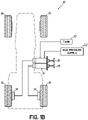
- FIG. 1A schematically illustrates an embodiment of a vehicle brake system 10 including an exemplary hydraulic brake assembly 12 in accordance with the principles of the present invention.
- the hydraulic brake assembly 12 provides pressurized hydraulic fluid to brake friction elements 14 associated with each of the wheels 16 of the vehicle to thereby retard or stop the rotational movement of the wheels 16 when brake pedal 18 is actuated by a user.
- a single brake pedal 18 actuates both cylinders of the brake assembly 12, as will be described below.
- the brake assembly 12 communicates with a supply of hydraulic fluid provided in a tank 20, and a high pressure supply of hydraulic fluid 22.
- the brake system may further include a pump, a hydraulic accumulator, or other suitable device for pressurizing the hydraulic fluid.
- FIG. 1B schematically illustrates another embodiment of a vehicle brake system 10a including an exemplary hydraulic brake assembly 12 in accordance with the principles of the present invention.
- individual brake pedals 18 may be depressed by a user to separately actuate the cylinders of the brake assembly 12, and each cylinder communicates with one of the brake friction elements 14 of the rear wheels 16 of a vehicle, for example.
- Such a configuration may be useful for agricultural tractors or other applications wherein individual actuation of the cylinders is desired, for example, to facilitate turning of the vehicle.
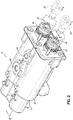
- the exemplary brake assembly 12 comprises a brake assembly housing 24 enclosing the components of the brake assembly, including one or more master cylinders, as will described in more detail below.
- the brake assembly 12 includes first and second master cylinders arranged side-by-side to define a dual master cylinder brake assembly. It will be appreciated, however, that various features of the inventive brake assembly described herein may be utilized in various other brake configurations. As non-limiting examples, various features of the inventive brake assembly described herein may be used in a tandem arrangement of master cylinders, or in a single master cylinder arrangement.
- the brake assembly 12 communicates with the supply of hydraulic fluid provided in tank 20 through a tank port 26, and communicates with the supply of high pressure fluid 22 through a boost port 28.
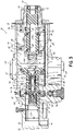
- First and second longitudinally extending housing bores are formed in the brake assembly housing in a side-by-side arrangement to define the dual master cylinder arrangement (only the first housing bore 30 is illustrated in FIG. 3 ). Because each master cylinder assembly of the brake assembly is constructed in the same manner, only one of the master cylinder arrangements will be described herein.
- Each master cylinder assembly includes a master cylinder piston 32 slidably disposed within the respective housing bore 30 for movement by actuation of brake pedal 18 to and between an inactive position (depicted in FIG. 3 ) and an active position (depicted in FIG. 4G ), as will be described more fully below.
- each master cylinder piston 32 may be individually moved by actuation of the respective brake pedals 18, as generally discussed above.
- Brake pedal 18 is coupled by brake rods 34 to a respective input rod 36 at a first, open end 38 of the brake housing 24.
- Each input rod 36 is slidably received in an aperture 40 of an input journal 42 at the first end 38 of the brake housing 24, and is sealed by a circumferentially extending seal 44 disposed between the input rod 36 and the inner diameter of the input journal 42.
- a second end 46 of the housing 24 is closed by an end wall 48, and cooperates with the master cylinder piston 32 to define a master cylinder chamber 50 which communicates with the brake friction elements 14 through respective brake ports 52 at the second end 46 of the housing 24.
- the master cylinder piston 32 comprises a first piston portion 60 having a first diameter D1 that cooperates with a corresponding inner diameter of the housing bore 30 to define a quick-fill chamber 62.
- the master cylinder piston 32 further includes a second piston portion 64 having a second diameter D2, smaller than the first diameter D1, and cooperating with a corresponding reduced inner diameter portion of the housing bore 30 to define the master cylinder chamber 50 between the second piston portion 64 and the end wall 48 of the housing 24.
- a biasing element shown herein in the form of a master cylinder spring 66, is disposed in the quick-fill chamber 62 and biases the master cylinder piston 32 in a direction toward the first end 38 of the housing 24 corresponding to the inactive position of the master cylinder piston 32 when no external force is applied to the brake pedal 18 to actuate the brakes.
- a longitudinally extending piston bore 70 is provided in the master cylinder piston 32 and communicates with the quick-fill chamber 62 through radially extending passages 72 in the master cylinder piston 32.
- a spool 74 is slidably disposed within the piston bore 70 and is sealed against the inner diameter of the piston bore 70 by one or more circumferentially extending seals 76.
- a longitudinally extending central passage 78 provided in the spool 74 communicates with the quick-fill chamber 62 through the radially extending passages 72 of the master cylinder piston 32 and corresponding radially extending passages 80 in the spool 74.
- a first check valve 82 may be provided at a first end 84 of the central passage 78 to control the flow of hydraulic fluid back to a recuperation chamber 86, as will be described in more detail below.
- a second check valve 88 may be provided at a second end 90 of the central passage 78 through the spool 74 to control the flow of hydraulic fluid through the central passage 78 for communication with the master cylinder chamber 50.
- the spool 74 is operable in a first mode to direct hydraulic fluid from the quick-fill chamber 62 through the second check valve 88 and into the master cylinder chamber 50 at a first pressure upon an initial movement of the master cylinder piston 32 from the inactive position toward the active position, such that any clearance between the friction elements 14 of the brakes is taken up.
- the spool 74 is also operable in a second mode to direct hydraulic fluid from the quick-fill chamber 62 to the tank 20 when pressure in the master cylinder chamber 50 reaches a predefined threshold.
- the predefined threshold may be set by preloading a spring 144 (described further below).
- the second check valve permits the passage of hydraulic fluid to the master cylinder chamber 50, and the first check valve 82 prevents hydraulic fluid from passing to the recuperation chamber 86.
- the brake assembly may further include a booster assembly 100 operatively coupled with the master cylinder piston 32 by a piston extension 102 to provide a boost force to the master cylinder piston 32 when the associated brake pedal 18 is actuated by a user.
- the booster assembly 100 includes a boost piston 110 slidably disposed within the housing bore 30.
- First and second lands 112, 114 are provided on the boost piston 110, with first and second circumferential seals 116, 118 sealingly engaging the first inner diameter of the housing bore 30.
- the first and second lands 112, 114 of the boost piston 110 cooperate with the housing bore 30 to define a boost chamber 120 therebetween.
- the boost chamber 120 communicates with the high pressure supply 22 through the boost port 28.
- the second land 114 of the boost piston 110 cooperates with the first master cylinder piston portion 60 to define the recuperation chamber 86 between the master cylinder piston 32 and the second land 114.
- a longitudinally extending boost bore 122 is provided in the boost piston 110, and a control valve 124 is slidably disposed within the boost bore 122.
- the control valve 124 is slidably moveable by actuation of the associated brake pedal 18 to and from a first position and a second position.
- a boost spring 126 provided at a distal end of the boost bore 122 biases the control valve 124 in a direction toward the first end 38 of the housing 24, corresponding with the first position of the control valve 124.
- An elongate passage 128 and radially extending passages 130 are provided in the control valve 124.
- First and second radially extending passages 132, 134 are provided in the boost piston 110 for communication between the boost chamber 120, the boost bore 122 and the recuperation chamber 86, as will be described below.
- First and second circumferential seals 136, 138 disposed between the control valve 124 and the boost bore 122 operate to open and close the radially extending passages 132, 134 in the boost piston 110 to control the flow of hydraulic fluid therethrough as the control valve 124 moves between the first and second positions.
- FIG. 3 depicts a cross-section of the exemplary brake assembly wherein no pressure is applied to the brake pedal 18 by a user, and the master cylinder piston 32 is in the inactive position, biased by the master cylinder spring 66 in a direction fully toward the first end 38 of the brake assembly housing 24.
- the first radial passages 132 in the boost piston 110 are closed off by the control valve 124, the recuperation chamber 86 is in communication with the tank 20 through the tank port 26, and the second radial passages 134 in the boost piston 110 are open so that hydraulic fluid may pass between boost bore 122 and the recuperation chamber 86.
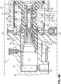
- the input rod 36 is moved in a direction toward the second end 46 of the brake assembly housing 24, as depicted in FIG. 4A . Movement of the input rod 36 causes the control valve 124 to move in a direction toward the second end 46 of the brake assembly housing 24, compressing the boost spring 126. Any air that may be trapped within the booster or the brake system may escape through one or more bleed passages 140, 142 formed in the master cylinder piston 32 and the brake assembly housing 24 in a direction toward the tank port 26 as generally depicted by arrows in FIG. 4B .
- the input rod 36 continues to move the control valve 124 toward the second end 46 of the brake housing 24, further compressing the boost spring 126 until the first radially extending passages 132 in the boost piston 110 are uncovered by the first circumferential seal 136 on the control valve 124, thereby establishing fluid communication between the boost chamber 120 and the boost bore 122 through the first radially extending passages 132 in the boost piston 110, the radially extending passages 130 in the control valve 124, and the elongate passage 128 in the control valve 124.
- the second circumferential seal 138 on the control valve 124 closes off the second radially extending passages 134 in the boost piston 110, thereby preventing fluid communication between the boost bore 122 and the recuperation chamber 86, as depicted in FIG. 4C .
- the increased pressure within the boost bore provides a boost force that facilitates movement of the master cylinder piston 32 in a direction toward the second end 46 of the brake assembly housing 24, as depicted in FIG. 4D .
- the boost force is proportional to the force applied to the input rod 36 by the user's foot on pedal 18, multiplied by the boost ratio.
- the boost ratio is the square of the ratio of the diameter D1 of the first piston portion 60 to the diameter of the aperture 40.
- movement of the master cylinder piston 32 compresses the master cylinder spring 66 and reduces the volume of the quick-fill chamber 62, thereby forcing hydraulic fluid through the radially extending passages 72, 80 in the master cylinder piston 32 and the spool 74 into the central passage 78 of the spool 74.
- the hydraulic fluid then flows through the second check valve 88 and into the master cylinder chamber 50 at the second end 46 of the brake assembly housing 24 for communication to the brake friction elements 14 via the brake port 52.
- the relatively large volume of hydraulic fluid forced from the quick-fill chamber 62 through the master cylinder chamber 50 and toward the brake friction elements 14 quickly takes up any running clearance between the friction elements 14.
- the boost piston 110 and master cylinder piston 32 continue to move in a direction toward the second end 46 of the brake assembly housing 24, wherein the smaller diameter of the second portion 64 of the master cylinder piston 32 forces an additional volume of hydraulic fluid to the brake friction elements 14 from the master cylinder chamber 50 at a pressure higher than the first pressure, as generally depicted in FIG. 4F .
- the higher pressure of the hydraulic fluid causes the friction elements 14 of the brakes to be activated for retarding and/or stopping the vehicle.
- the pressure of the hydraulic fluid to the brakes will be maintained while the user's foot remains on the brake pedal 18, as generally depicted in FIG. 4G .
- the boost spring 126 biases the control valve 124 in the direction of the first end 38 of the brake assembly housing 24.
- the first circumferential seal 136 on the control valve 124 closes off the radially extending passages 132 between the elongate passage 128 of the control valve 124 and the boost chamber 120, and the second circumferential 138 seal moves to open the radially extending passages 134 between the boost bore 122 and the recuperation chamber 86, whereby hydraulic fluid in the central passage 128 may flow into the recuperation chamber 86 communicating with the tank 20, as depicted in FIG. 4I .
- the boost force is removed and the master cylinder spring 66 begins to move the master cylinder piston 32 in the direction of the first end 38 of the brake assembly housing 24, back toward the inactive position of the master cylinder piston 32. Movement of the master cylinder piston 32 toward the inactive position moves circumferentially extending seals 148 on the master cylinder piston 32 to undercover the bleed passage 140, thereby facilitating the flow of hydraulic fluid from the brakes and the master cylinder chamber 50 in the direction of the quick-fill chamber 62 as the quick-fill chamber volume increases, as illustrated in FIG. 4J .
- the spool spring 144 moves the spool 74 relative to the master cylinder piston 32 in a direction toward the second end 46 of the brake assembly housing 24.
- hydraulic fluid flows from the recuperation chamber 86 through the extension piston 102 and the first check valve 82 into the central passage 78 of the spool 74.
- hydraulic fluid flows through the radially extending passages 80, 72 in the spool 74 and the master cylinder piston 32 into the quick-fill chamber 62, as depicted in FIG. 4K .
- Additional hydraulic fluid may be directed from the recuperation chamber 86 through passages 150 in the brake assembly housing 24 and recuperation valves 152 positioned below the bores 30 in the brake assembly housing 24, as illustrated in FIG. 4L .
- the brake assembly 12 With the master cylinder piston 32 and boost piston 110 in their original positions as depicted in FIG. 2 , the brake assembly 12 is in the inactive condition and ready for further application of braking forces as described above.
Landscapes
- Engineering & Computer Science (AREA)
- Transportation (AREA)
- Mechanical Engineering (AREA)
- Braking Systems And Boosters (AREA)
- Transmission Of Braking Force In Braking Systems (AREA)
Description
- This application claims the benefit of
U.S. Provisional Patent Application Serial No. 62/376,481, filed August 18, 2016 - The present invention relates generally to vehicle brake systems and, more particularly, to an improved boosted brake master cylinder assembly having a quick-fill function.
- In the design and development of vehicles, there is a continued effort to achieve increased fuel efficiencies, particularly for Class 8 trucks or other industrial vehicles. One strategy of this effort for improved fuel efficiency involves increasing brake running clearances. While these increased running clearances facilitate fuel efficient operation, they also require more hydraulic fluid volume in order to take up the clearances when brakes are applied to slow or stop a vehicle. Thereby requiring more energy devoted to providing additional hydraulic pressure. A need exists for an improved, efficient, and compact brake system that accommodates larger brake running clearances, and which can achieve the take up of these clearances upon activation of the brakes without the need for additional hydraulic power components for pressurizing hydraulic fluid in the system.
-
US 4,444,440 A describes a hydraulic booster having a housing provided with an input member, a boost piston, an output member, and connections to a source of pressure and a fluid reservoir. A force applied to the input member is transmitted to the output member and augmented by the boost piston in response to pressurization of a boost chamber controlled by a valve mechanism in response to operation of the input member. An auxiliary chamber is defined between the boost piston and the output member. In a first stage of operation to take up lost-motion in the system, the auxiliary chamber is supplied with fluid from the source to advance the output member relative to the boost piston through a distance determined by a limiting mechanism. In a second stage of operation the output member and the boost piston move together in response to pressurization of the boost chamber. The area of the boost piston on which the auxiliary pressure acts is greater than or equal to the effective area of the boost piston. - The present invention provides a hydraulic brake assembly with a quick-fill function that takes up any running clearances in the brakes upon initial application of the brakes by a user. After the running clearances have been taken up, continued application of force to the brake pedal by the user actuates the brakes to retard or stop the vehicle. While the invention will be described in connection with certain embodiments, it will be understood that the invention is not limited to these embodiments.
- In one aspect, a hydraulic brake assembly in accordance with the principles of the present disclosure includes a brake assembly housing and first and second housing bores in the brake assembly housing, arranged side-by-side. Each of the first and second bores defines a respective master cylinder assembly, and each master cylinder assembly includes a master cylinder piston slidably disposed in the respective housing bore and movable by actuation of a respective brake pedal to and between an active position and an inactive position. The master cylinder piston has a first diameter and a second diameter. The first diameter cooperates with the housing bore to define a variable volume quick-fill chamber, and the second diameter cooperates with the housing bore to define a variable volume master cylinder chamber.
- The master cylinder assembly further includes a piston bore in the master cylinder piston and communicating with the quick-fill chamber. A spool is slidably disposed within the piston bore and is operable in a first mode to direct hydraulic fluid from the quick-fill chamber to the master cylinder chamber and the brakes at a first pressure upon initial movement of the master cylinder piston from the inactive position toward the active position. The hydraulic fluid from the quick-fill chamber takes up any clearance between the friction elements of the brakes. The spool is operable in a second mode to direct hydraulic fluid from the quick-fill chamber to a tank when pressure in the master cylinder chamber reaches a predefined threshold, whereafter continued movement of the master cylinder piston toward the active position provides hydraulic fluid to the friction elements of the brakes at a second pressure higher than the first pressure.
- The above and other objects and advantages of the present invention will be apparent from the accompanying drawings and the description thereof.
- The accompanying drawings, which are incorporated in and constitute a part of this specification, illustrate exemplary embodiments of the invention and, together with a general description of the invention given above, and the detailed description given below, serve to explain the principles of the invention.
-
FIG. 1A is a schematic illustration of a vehicle brake system including an exemplary brake assembly in accordance with the principles of the present disclosure. -
FIG. 1B is a schematic illustration of another embodiment of vehicle brake system including an exemplary brake assembly in accordance with the principles of the present disclosure. -
FIG. 2 is a perspective view of an exemplary dual master cylinder brake assembly in accordance with the principles of the present disclosure. -
FIG. 3 is a cross-sectional view of the brake assembly ofFIG. 1 , taken along line 2-2. -
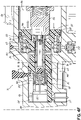
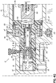
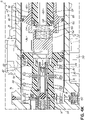
FIGS. 4A-4L are cross-sectional views of the brake assembly ofFIG. 2 , similar toFIG. 3 , and illustrating operation of the brake assembly. -
FIG. 1A schematically illustrates an embodiment of a vehicle brake system 10 including an exemplaryhydraulic brake assembly 12 in accordance with the principles of the present invention. Thehydraulic brake assembly 12 provides pressurized hydraulic fluid tobrake friction elements 14 associated with each of thewheels 16 of the vehicle to thereby retard or stop the rotational movement of thewheels 16 whenbrake pedal 18 is actuated by a user. In the embodiment shown, asingle brake pedal 18 actuates both cylinders of thebrake assembly 12, as will be described below. Thebrake assembly 12 communicates with a supply of hydraulic fluid provided in atank 20, and a high pressure supply ofhydraulic fluid 22. The brake system may further include a pump, a hydraulic accumulator, or other suitable device for pressurizing the hydraulic fluid. -
FIG. 1B schematically illustrates another embodiment of a vehicle brake system 10a including an exemplaryhydraulic brake assembly 12 in accordance with the principles of the present invention. In this embodiment,individual brake pedals 18 may be depressed by a user to separately actuate the cylinders of thebrake assembly 12, and each cylinder communicates with one of thebrake friction elements 14 of therear wheels 16 of a vehicle, for example. Such a configuration may be useful for agricultural tractors or other applications wherein individual actuation of the cylinders is desired, for example, to facilitate turning of the vehicle. - Referring now to
FIGS. 2 and3 , theexemplary brake assembly 12 comprises abrake assembly housing 24 enclosing the components of the brake assembly, including one or more master cylinders, as will described in more detail below. In the embodiment shown, thebrake assembly 12 includes first and second master cylinders arranged side-by-side to define a dual master cylinder brake assembly. It will be appreciated, however, that various features of the inventive brake assembly described herein may be utilized in various other brake configurations. As non-limiting examples, various features of the inventive brake assembly described herein may be used in a tandem arrangement of master cylinders, or in a single master cylinder arrangement. Thebrake assembly 12 communicates with the supply of hydraulic fluid provided intank 20 through atank port 26, and communicates with the supply ofhigh pressure fluid 22 through aboost port 28. - First and second longitudinally extending housing bores are formed in the brake assembly housing in a side-by-side arrangement to define the dual master cylinder arrangement (only the
first housing bore 30 is illustrated inFIG. 3 ). Because each master cylinder assembly of the brake assembly is constructed in the same manner, only one of the master cylinder arrangements will be described herein. Each master cylinder assembly includes amaster cylinder piston 32 slidably disposed within therespective housing bore 30 for movement by actuation ofbrake pedal 18 to and between an inactive position (depicted inFIG. 3 ) and an active position (depicted inFIG. 4G ), as will be described more fully below. In the alternative embodiment depicted inFIG. 1B , eachmaster cylinder piston 32 may be individually moved by actuation of therespective brake pedals 18, as generally discussed above. -
Brake pedal 18 is coupled bybrake rods 34 to arespective input rod 36 at a first,open end 38 of thebrake housing 24. Eachinput rod 36 is slidably received in anaperture 40 of aninput journal 42 at thefirst end 38 of thebrake housing 24, and is sealed by a circumferentially extendingseal 44 disposed between theinput rod 36 and the inner diameter of theinput journal 42. Asecond end 46 of thehousing 24 is closed by anend wall 48, and cooperates with themaster cylinder piston 32 to define amaster cylinder chamber 50 which communicates with thebrake friction elements 14 throughrespective brake ports 52 at thesecond end 46 of thehousing 24. - With continued reference to
FIG. 3 , themaster cylinder piston 32 comprises afirst piston portion 60 having a first diameter D1 that cooperates with a corresponding inner diameter of thehousing bore 30 to define a quick-fill chamber 62. Themaster cylinder piston 32 further includes asecond piston portion 64 having a second diameter D2, smaller than the first diameter D1, and cooperating with a corresponding reduced inner diameter portion of the housing bore 30 to define themaster cylinder chamber 50 between thesecond piston portion 64 and theend wall 48 of thehousing 24. A biasing element, shown herein in the form of amaster cylinder spring 66, is disposed in the quick-fill chamber 62 and biases themaster cylinder piston 32 in a direction toward thefirst end 38 of thehousing 24 corresponding to the inactive position of themaster cylinder piston 32 when no external force is applied to thebrake pedal 18 to actuate the brakes. - A longitudinally extending piston bore 70 is provided in the
master cylinder piston 32 and communicates with the quick-fill chamber 62 through radially extendingpassages 72 in themaster cylinder piston 32. Aspool 74 is slidably disposed within the piston bore 70 and is sealed against the inner diameter of the piston bore 70 by one or more circumferentially extending seals 76. A longitudinally extendingcentral passage 78 provided in thespool 74 communicates with the quick-fill chamber 62 through theradially extending passages 72 of themaster cylinder piston 32 and corresponding radially extendingpassages 80 in thespool 74. Afirst check valve 82 may be provided at afirst end 84 of thecentral passage 78 to control the flow of hydraulic fluid back to arecuperation chamber 86, as will be described in more detail below. Asecond check valve 88 may be provided at asecond end 90 of thecentral passage 78 through thespool 74 to control the flow of hydraulic fluid through thecentral passage 78 for communication with themaster cylinder chamber 50. - The
spool 74 is operable in a first mode to direct hydraulic fluid from the quick-fill chamber 62 through thesecond check valve 88 and into themaster cylinder chamber 50 at a first pressure upon an initial movement of themaster cylinder piston 32 from the inactive position toward the active position, such that any clearance between thefriction elements 14 of the brakes is taken up. Thespool 74 is also operable in a second mode to direct hydraulic fluid from the quick-fill chamber 62 to thetank 20 when pressure in themaster cylinder chamber 50 reaches a predefined threshold. The predefined threshold may be set by preloading a spring 144 (described further below). When the pressure in themaster cylinder chamber 50 reaches the predefined threshold, continued movement of themaster cylinder piston 32 toward the active position provides hydraulic fluid to thefriction elements 14 of the brakes at a second pressure that is higher than the first pressure for actuation of the brakes. In the first mode of operation the second check valve permits the passage of hydraulic fluid to themaster cylinder chamber 50, and thefirst check valve 82 prevents hydraulic fluid from passing to therecuperation chamber 86. - The brake assembly may further include a
booster assembly 100 operatively coupled with themaster cylinder piston 32 by apiston extension 102 to provide a boost force to themaster cylinder piston 32 when the associatedbrake pedal 18 is actuated by a user. In the embodiment shown, thebooster assembly 100 includes aboost piston 110 slidably disposed within the housing bore 30. First andsecond lands boost piston 110, with first and secondcircumferential seals second lands boost piston 110 cooperate with the housing bore 30 to define aboost chamber 120 therebetween. Theboost chamber 120 communicates with thehigh pressure supply 22 through theboost port 28. Thesecond land 114 of theboost piston 110 cooperates with the first mastercylinder piston portion 60 to define therecuperation chamber 86 between themaster cylinder piston 32 and thesecond land 114. - A longitudinally extending boost bore 122 is provided in the
boost piston 110, and acontrol valve 124 is slidably disposed within the boost bore 122. Thecontrol valve 124 is slidably moveable by actuation of the associatedbrake pedal 18 to and from a first position and a second position. Aboost spring 126 provided at a distal end of the boost bore 122 biases thecontrol valve 124 in a direction toward thefirst end 38 of thehousing 24, corresponding with the first position of thecontrol valve 124. Anelongate passage 128 and radially extendingpassages 130 are provided in thecontrol valve 124. First and second radially extendingpassages boost piston 110 for communication between theboost chamber 120, the boost bore 122 and therecuperation chamber 86, as will be described below. First and secondcircumferential seals control valve 124 and the boost bore 122 operate to open and close theradially extending passages boost piston 110 to control the flow of hydraulic fluid therethrough as thecontrol valve 124 moves between the first and second positions. - With continued reference to
FIG. 3 , and referring further toFIGS. 4A-4L , operation of thebrake assembly 12 will now be described.FIG. 3 depicts a cross-section of the exemplary brake assembly wherein no pressure is applied to thebrake pedal 18 by a user, and themaster cylinder piston 32 is in the inactive position, biased by themaster cylinder spring 66 in a direction fully toward thefirst end 38 of thebrake assembly housing 24. In this position, the firstradial passages 132 in theboost piston 110 are closed off by thecontrol valve 124, therecuperation chamber 86 is in communication with thetank 20 through thetank port 26, and the secondradial passages 134 in theboost piston 110 are open so that hydraulic fluid may pass between boost bore 122 and therecuperation chamber 86. As pressure is applied to thebrake pedal 18 by a user, theinput rod 36 is moved in a direction toward thesecond end 46 of thebrake assembly housing 24, as depicted inFIG. 4A . Movement of theinput rod 36 causes thecontrol valve 124 to move in a direction toward thesecond end 46 of thebrake assembly housing 24, compressing theboost spring 126. Any air that may be trapped within the booster or the brake system may escape through one ormore bleed passages master cylinder piston 32 and thebrake assembly housing 24 in a direction toward thetank port 26 as generally depicted by arrows inFIG. 4B . - As the
brake pedal 18 is further depressed, theinput rod 36 continues to move thecontrol valve 124 toward thesecond end 46 of thebrake housing 24, further compressing theboost spring 126 until the firstradially extending passages 132 in theboost piston 110 are uncovered by the firstcircumferential seal 136 on thecontrol valve 124, thereby establishing fluid communication between theboost chamber 120 and the boost bore 122 through the firstradially extending passages 132 in theboost piston 110, theradially extending passages 130 in thecontrol valve 124, and theelongate passage 128 in thecontrol valve 124. At the same time, the secondcircumferential seal 138 on thecontrol valve 124 closes off the secondradially extending passages 134 in theboost piston 110, thereby preventing fluid communication between the boost bore 122 and therecuperation chamber 86, as depicted inFIG. 4C . The increased pressure within the boost bore provides a boost force that facilitates movement of themaster cylinder piston 32 in a direction toward thesecond end 46 of thebrake assembly housing 24, as depicted inFIG. 4D . The boost force is proportional to the force applied to theinput rod 36 by the user's foot onpedal 18, multiplied by the boost ratio. In the embodiment shown, the boost ratio is the square of the ratio of the diameter D1 of thefirst piston portion 60 to the diameter of theaperture 40. - With continued reference to
FIG. 4D , movement of themaster cylinder piston 32 compresses themaster cylinder spring 66 and reduces the volume of the quick-fill chamber 62, thereby forcing hydraulic fluid through theradially extending passages master cylinder piston 32 and thespool 74 into thecentral passage 78 of thespool 74. The hydraulic fluid then flows through thesecond check valve 88 and into themaster cylinder chamber 50 at thesecond end 46 of thebrake assembly housing 24 for communication to thebrake friction elements 14 via thebrake port 52. The relatively large volume of hydraulic fluid forced from the quick-fill chamber 62 through themaster cylinder chamber 50 and toward thebrake friction elements 14 quickly takes up any running clearance between thefriction elements 14. As hydraulic fluid is forced from the quick-fill chamber 62 into themaster cylinder chamber 50, pressure begins to build in themaster cylinder chamber 50. As this pressure builds, fluid flow back through thecentral passage 78 of thespool 74 is prevented by thesecond check valve 88, and the spool biasing element, shown herein in the form of aspring 144, begins to compress, whereby thespool 74 is moved relative to themaster cylinder piston 32 in a direction toward thefirst end 38 of thebrake assembly housing 24, as depicted inFIG. 4E . - As the
spool 74 reaches its limit of travel in the direction of thefirst end 38 of thebrake cylinder housing 24,fluid passages 146 between the piston bore 78 and therecuperation chamber 86 are opened, whereby further hydraulic fluid from the quick-fill chamber 62 is now directed to therecuperation chamber 86 for communication with thetank 20 through thetank port 26 in the second mode of operation of thespool 74, thereby ceasing the quick-fill function of thebrake assembly 12. With continued pressure applied to thebrake pedal 18, theboost piston 110 andmaster cylinder piston 32 continue to move in a direction toward thesecond end 46 of thebrake assembly housing 24, wherein the smaller diameter of thesecond portion 64 of themaster cylinder piston 32 forces an additional volume of hydraulic fluid to thebrake friction elements 14 from themaster cylinder chamber 50 at a pressure higher than the first pressure, as generally depicted inFIG. 4F . The higher pressure of the hydraulic fluid causes thefriction elements 14 of the brakes to be activated for retarding and/or stopping the vehicle. The pressure of the hydraulic fluid to the brakes will be maintained while the user's foot remains on thebrake pedal 18, as generally depicted inFIG. 4G . - Referring now to
FIG. 4H , operation of thebrake assembly 12 to release the brakes will now be described. As the user releases pressure on thebrake pedal 18, theboost spring 126 biases thecontrol valve 124 in the direction of thefirst end 38 of thebrake assembly housing 24. The firstcircumferential seal 136 on thecontrol valve 124 closes off theradially extending passages 132 between theelongate passage 128 of thecontrol valve 124 and theboost chamber 120, and the second circumferential 138 seal moves to open theradially extending passages 134 between the boost bore 122 and therecuperation chamber 86, whereby hydraulic fluid in thecentral passage 128 may flow into therecuperation chamber 86 communicating with thetank 20, as depicted inFIG. 4I . As the pressure in the boost bore 122 is reduced, the boost force is removed and themaster cylinder spring 66 begins to move themaster cylinder piston 32 in the direction of thefirst end 38 of thebrake assembly housing 24, back toward the inactive position of themaster cylinder piston 32. Movement of themaster cylinder piston 32 toward the inactive position moves circumferentially extendingseals 148 on themaster cylinder piston 32 to undercover thebleed passage 140, thereby facilitating the flow of hydraulic fluid from the brakes and themaster cylinder chamber 50 in the direction of the quick-fill chamber 62 as the quick-fill chamber volume increases, as illustrated inFIG. 4J . - As the pressure in the
master cylinder chamber 50 reduces, thespool spring 144 moves thespool 74 relative to themaster cylinder piston 32 in a direction toward thesecond end 46 of thebrake assembly housing 24. As themaster cylinder piston 32 moves toward thefirst end 38 of thebrake assembly housing 24 and the volume of the quick-fill chamber 62 is increased, hydraulic fluid flows from therecuperation chamber 86 through theextension piston 102 and thefirst check valve 82 into thecentral passage 78 of thespool 74. Thereafter, hydraulic fluid flows through theradially extending passages spool 74 and themaster cylinder piston 32 into the quick-fill chamber 62, as depicted inFIG. 4K . - Additional hydraulic fluid may be directed from the
recuperation chamber 86 throughpassages 150 in thebrake assembly housing 24 andrecuperation valves 152 positioned below thebores 30 in thebrake assembly housing 24, as illustrated inFIG. 4L . With themaster cylinder piston 32 andboost piston 110 in their original positions as depicted inFIG. 2 , thebrake assembly 12 is in the inactive condition and ready for further application of braking forces as described above.
Claims (14)
- A hydraulic brake assembly (12) for use with a vehicle having brakes with friction elements (14) for stopping the wheels (16) of a vehicle and a supply of hydraulic fluid for the brake assembly (12), the hydraulic brake assembly (12) including one or more master cylinder assemblies in a brake assembly housing (24) having one or more housing bores (30) arranged side-by-side for housing a respective master cylinder assembly;
each of the one or more master cylinder assemblies comprising:a master cylinder piston (32) slidably disposed in the respective housing bore (30) and movable by actuation of a brake pedal (18) between an active position and an inactive position,the master cylinder piston (32) having a first diameter (D1) and a second diameter (D2),the first diameter (D1) cooperating with the housing bore (30) to define a variable volume quick-fill chamber (62),the second diameter (D2) cooperating with the housing bore (30) to define a variable volume master cylinder chamber (50),the master cylinder piston (32) including a piston bore (70) communicating with the quick-fill chamber (62), anda spool (74) slidably disposed within the piston bore (70),characterised in that the spool (74) is operable in a first mode to direct hydraulic fluid from the quick-fill chamber (62) to the master cylinder chamber (50) and the brakes at a first pressure upon initial movement of the master cylinder piston (32) from the inactive position toward the active position for taking up any clearance between the friction elements (14) of the brakes, andthe spool (74) is operable in a second mode on further movement of the master cylinder piston (32) to direct hydraulic fluid from the quick-fill chamber (62) to the supply of hydraulic fluid when pressure in the master cylinder chamber (50) reaches a predefined threshold, and continued movement of the master cylinder piston (32) toward the active position provides hydraulic fluid to the friction elements (14) of the brakes at a second pressure higher than the first pressure. - The hydraulic brake assembly (12) of claim 1, further comprising a first check valve (82) and a second check valve (88) cooperating with the spool (74) of the master cylinder piston (32), the first and second check valves (82, 88) controlling the passage of hydraulic fluid from the quick-fill chamber (62) to the master cylinder chamber (50) or from the supply of hydraulic fluid to the quick-fill chamber (62).
- The hydraulic brake assembly (12) of claim 2, wherein the second check valve (88) controls the passage of hydraulic fluid from the quick-fill chamber (62) to the master cylinder chamber (50) in the first mode of the master cylinder piston (32) in the active position.
- The hydraulic brake assembly (12) of any preceding claim, further comprising a biasing element cooperating with the spool (74), the biasing element biasing the spool (74) within the piston bore (70) toward a position associated with the first mode of operation.
- The hydraulic brake assembly (12) of any preceding claim, wherein the first diameter (D1) is greater than the second diameter (D2).
- The hydraulic brake assembly (12) of any preceding claim, further comprising:
a booster assembly (100) operatively coupled with the master cylinder piston (32) and providing a boost force to the master cylinder piston (32) when the respective brake pedal (18) is actuated. - The hydraulic brake assembly (12) of claim 6, wherein the booster assembly (100) comprises:a boost piston (110) slidably disposed in the respective housing bore (30);the boost piston (110) cooperating with the first diameter (D1) of the master cylinder piston (32) to define a recuperation chamber (86);the boost piston (110) cooperating with the housing bore (30) to define a boost chamber (120) operatively communicating with a high pressure supply.
- The hydraulic brake assembly (12) of claim 7, further comprisinga boost bore (122) in the boost piston (110);a control valve (124) slidably disposed within the boost bore (122) and movable by actuation of the respective brake pedal (18) to and from a first position and a second position;the first position of the control valve (124) providing fluid communication between the boost bore (122) and the recuperation chamber (86); andthe second position of the control valve (124) closing off the communication between the boost bore (122) and the recuperation chamber (86), and providing fluid communication between the boost bore (122) and the boost chamber (120).
- The hydraulic brake assembly (12) of claim 7, further comprising a biasing element cooperating with the control valve (124), the biasing element biasing the control valve (124) within the boost bore (122) toward the first position.
- The hydraulic brake assembly (12) of claim 7 further comprising first radial extending passages (132) in the boost piston (110) for providing fluid communication between the boost bore (122) and the boost chamber (120) in the second position of the control valve (124).
- The hydraulic brake assembly (12) of claim 7 further comprising second radial extending passages (134) in the boost piston (110) for providing fluid communication between the boost bore (122) and the recuperation chamber (86) in the first position of the control valve (124).
- The hydraulic brake assembly (12) of claim 2, comprising a recuperation chamber (86) formed in the housing bore (30) and in communication with the supply of hydraulic fluid, the first check valve (82) controlling passage of the hydraulic fluid from the recuperation chamber (86) to the quick-fill chamber (62) when the master cylinder piston (32) is in the inactive position.
- The hydraulic brake assembly (12) of any proceeding claim, further comprising a biasing element coupled between the housing bore (30) and the master cylinder piston (32) for biasing the master cylinder piston (32) to the inactive position.
- The hydraulic brake assembly (12) of claim 1, further comprising:
a booster assembly (100) operatively coupled with the master cylinder piston (32) and providing a boost force to the master cylinder piston (32) when the brake pedal (18) is actuated to move the master cylinder piston (32) from the inactive position toward the active position, the booster assembly (100) including:a boost piston (110) slidably disposed in the respective housing bore (30);the boost piston (110) cooperating with the housing bore (30) to define a boost chamber (120) operatively communicating with a high pressure supply for providing the boost force when the brake pedal (18) is actuated.
Applications Claiming Priority (2)
| Application Number | Priority Date | Filing Date | Title |
|---|---|---|---|
| US201662376481P | 2016-08-18 | 2016-08-18 | |
| PCT/US2017/047314 WO2018035306A1 (en) | 2016-08-18 | 2017-08-17 | Dual master cylinder brake assembly with quick-fill function |
Publications (3)
| Publication Number | Publication Date |
|---|---|
| EP3500463A1 EP3500463A1 (en) | 2019-06-26 |
| EP3500463A4 EP3500463A4 (en) | 2020-06-10 |
| EP3500463B1 true EP3500463B1 (en) | 2022-04-06 |
Family
ID=61197086
Family Applications (1)
| Application Number | Title | Priority Date | Filing Date |
|---|---|---|---|
| EP17842105.3A Active EP3500463B1 (en) | 2016-08-18 | 2017-08-17 | Dual master cylinder brake assembly with quick-fill function |
Country Status (7)
| Country | Link |
|---|---|
| US (1) | US11173887B2 (en) |
| EP (1) | EP3500463B1 (en) |
| KR (1) | KR102401246B1 (en) |
| CN (1) | CN109803862B (en) |
| AR (1) | AR109381A1 (en) |
| ES (1) | ES2912622T3 (en) |
| WO (1) | WO2018035306A1 (en) |
Families Citing this family (4)
| Publication number | Priority date | Publication date | Assignee | Title |
|---|---|---|---|---|
| IT201800005911A1 (en) * | 2018-05-31 | 2019-12-01 | DRIVE PUMP OF A BRAKING SYSTEM FOR VEHICLES AND RELATIVE BRAKING SYSTEM FOR VEHICLES | |
| CN109404447B (en) * | 2018-12-28 | 2024-03-08 | 芜湖稳乐制动系统有限公司 | Vehicle brake pump |
| CN112810592A (en) * | 2021-03-05 | 2021-05-18 | 江苏沃得农业机械股份有限公司 | Double-circuit two-stage pressure booster brake pump |
| CN112810590A (en) * | 2021-03-05 | 2021-05-18 | 江苏沃得农业机械股份有限公司 | Double-circuit two-stage pressure booster brake pump |
Family Cites Families (12)
| Publication number | Priority date | Publication date | Assignee | Title |
|---|---|---|---|---|
| US2453852A (en) * | 1947-01-24 | 1948-11-16 | Wagner Electric Corp | Mechanism for selective operation of a plurality of master cylinders |
| JPS4927809B1 (en) * | 1966-11-24 | 1974-07-20 | ||
| US3937021A (en) * | 1974-07-01 | 1976-02-10 | The Bendix Corporation | Hold off valve for a two stage servomotor |
| US4444440A (en) * | 1981-04-23 | 1984-04-24 | Lucas Industries Public Limited Company | Hydraulic boosters for vehicle braking systems |
| US4445334A (en) * | 1981-08-26 | 1984-05-01 | General Motors Corporation | Quick take-up master cylinder |
| GB2129520B (en) * | 1982-11-02 | 1986-06-11 | Lucas Ind Plc | A master cylinder assembly for a vehicle hydraulic braking system |
| JP3414033B2 (en) | 1995-03-13 | 2003-06-09 | トヨタ自動車株式会社 | Brake system |
| GB0218167D0 (en) * | 2002-08-06 | 2002-09-11 | Meritor Heavy Vehicle Braking | In line vacuum bleeding device |
| GB0704431D0 (en) * | 2007-03-08 | 2007-04-18 | Ap Racing Ltd | Differential hydraulic master cylinder |
| US8661812B2 (en) | 2010-02-03 | 2014-03-04 | Kelsey-Hayes Company | Hydraulic brake system with controlled boost |
| US8671679B2 (en) * | 2010-07-09 | 2014-03-18 | Robert Bosch Gmbh | Fast fill tandem master cylinder |
| KR101315063B1 (en) * | 2012-01-25 | 2013-10-08 | 주식회사 만도 | Pre-fill system to improve brake feeling and method for flux increase beginning thereof |
-
2017
- 2017-08-17 KR KR1020197005249A patent/KR102401246B1/en active Active
- 2017-08-17 CN CN201780062680.1A patent/CN109803862B/en active Active
- 2017-08-17 EP EP17842105.3A patent/EP3500463B1/en active Active
- 2017-08-17 ES ES17842105T patent/ES2912622T3/en active Active
- 2017-08-17 US US16/325,496 patent/US11173887B2/en active Active
- 2017-08-17 WO PCT/US2017/047314 patent/WO2018035306A1/en not_active Ceased
- 2017-08-18 AR ARP170102313A patent/AR109381A1/en active IP Right Grant
Also Published As
| Publication number | Publication date |
|---|---|
| KR20190043541A (en) | 2019-04-26 |
| ES2912622T3 (en) | 2022-05-26 |
| US20190210578A1 (en) | 2019-07-11 |
| CN109803862A (en) | 2019-05-24 |
| EP3500463A1 (en) | 2019-06-26 |
| US11173887B2 (en) | 2021-11-16 |
| KR102401246B1 (en) | 2022-05-23 |
| WO2018035306A1 (en) | 2018-02-22 |
| EP3500463A4 (en) | 2020-06-10 |
| CN109803862B (en) | 2022-01-28 |
| AR109381A1 (en) | 2018-11-28 |
Similar Documents
| Publication | Publication Date | Title |
|---|---|---|
| US6305758B1 (en) | Electro-hydraulic actuator for motor vehicle brake | |
| EP3500463B1 (en) | Dual master cylinder brake assembly with quick-fill function | |
| CN105073530A (en) | Brakes for braking systems of vehicles and braking systems for vehicles | |
| CN209441353U (en) | Braking device for hydraulic motor vehicle braking system | |
| CN102099232A (en) | On-demand power brake system and method | |
| JP2013514933A (en) | Hydraulic vehicle brake device | |
| JPH0674543U (en) | Actuator of hydraulic brake system with slip control | |
| US4444440A (en) | Hydraulic boosters for vehicle braking systems | |
| JPS61146665A (en) | Power brake booster for hydraulic brake system | |
| JP2876336B2 (en) | Hydraulic pressure control device | |
| US6082831A (en) | Electro-hydraulic brake apply system displacement augmentation | |
| GB2098687A (en) | A twin master cylinder or booster assembly for a vehicle braking system | |
| EP1064179B1 (en) | Fluid control valve and braking system incorporating such a valve | |
| JP2008265431A (en) | Master cylinder and hydraulic control system | |
| EP2749462B1 (en) | Hydraulic braking system and method of brake boosting in a motor vehicle | |
| EP1114761B1 (en) | Dual hydraulic booster assembly for vehicle hydraulic braking systems | |
| JPH08529B2 (en) | Automotive hydraulic brake device | |
| US4232520A (en) | Actuator assemblies for vehicle hydraulic braking systems | |
| EP1538045B1 (en) | Hydraulic controller | |
| JP3932153B2 (en) | Brake system | |
| EP3397536B1 (en) | Hydraulic device for controlling braking for farm vehicles and the like | |
| JP2813916B2 (en) | Hydraulic pressure control valve | |
| JP4765196B2 (en) | Hydraulic brake device | |
| EP2663478B1 (en) | Master cylinder | |
| JP3932152B2 (en) | Brake hydraulic boost system |
Legal Events
| Date | Code | Title | Description |
|---|---|---|---|
| STAA | Information on the status of an ep patent application or granted ep patent |
Free format text: STATUS: THE INTERNATIONAL PUBLICATION HAS BEEN MADE |
|
| PUAI | Public reference made under article 153(3) epc to a published international application that has entered the european phase |
Free format text: ORIGINAL CODE: 0009012 |
|
| STAA | Information on the status of an ep patent application or granted ep patent |
Free format text: STATUS: REQUEST FOR EXAMINATION WAS MADE |
|
| 17P | Request for examination filed |
Effective date: 20190312 |
|
| AK | Designated contracting states |
Kind code of ref document: A1 Designated state(s): AL AT BE BG CH CY CZ DE DK EE ES FI FR GB GR HR HU IE IS IT LI LT LU LV MC MK MT NL NO PL PT RO RS SE SI SK SM TR |
|
| AX | Request for extension of the european patent |
Extension state: BA ME |
|
| DAV | Request for validation of the european patent (deleted) | ||
| DAX | Request for extension of the european patent (deleted) | ||
| A4 | Supplementary search report drawn up and despatched |
Effective date: 20200511 |
|
| RIC1 | Information provided on ipc code assigned before grant |
Ipc: B60T 11/10 20060101ALI20200504BHEP Ipc: B60T 11/224 20060101AFI20200504BHEP Ipc: B60T 11/228 20060101ALI20200504BHEP Ipc: B60T 11/16 20060101ALI20200504BHEP Ipc: B60T 11/20 20060101ALI20200504BHEP Ipc: B60T 11/21 20060101ALI20200504BHEP |
|
| STAA | Information on the status of an ep patent application or granted ep patent |
Free format text: STATUS: EXAMINATION IS IN PROGRESS |
|
| 17Q | First examination report despatched |
Effective date: 20210118 |
|
| GRAP | Despatch of communication of intention to grant a patent |
Free format text: ORIGINAL CODE: EPIDOSNIGR1 |
|
| STAA | Information on the status of an ep patent application or granted ep patent |
Free format text: STATUS: GRANT OF PATENT IS INTENDED |
|
| INTG | Intention to grant announced |
Effective date: 20211029 |
|
| GRAS | Grant fee paid |
Free format text: ORIGINAL CODE: EPIDOSNIGR3 |
|
| GRAA | (expected) grant |
Free format text: ORIGINAL CODE: 0009210 |
|
| STAA | Information on the status of an ep patent application or granted ep patent |
Free format text: STATUS: THE PATENT HAS BEEN GRANTED |
|
| AK | Designated contracting states |
Kind code of ref document: B1 Designated state(s): AL AT BE BG CH CY CZ DE DK EE ES FI FR GB GR HR HU IE IS IT LI LT LU LV MC MK MT NL NO PL PT RO RS SE SI SK SM TR |
|
| REG | Reference to a national code |
Ref country code: GB Ref legal event code: FG4D |
|
| REG | Reference to a national code |
Ref country code: CH Ref legal event code: EP |
|
| REG | Reference to a national code |
Ref country code: AT Ref legal event code: REF Ref document number: 1481075 Country of ref document: AT Kind code of ref document: T Effective date: 20220415 |
|
| REG | Reference to a national code |
Ref country code: IE Ref legal event code: FG4D |
|
| REG | Reference to a national code |
Ref country code: DE Ref legal event code: R096 Ref document number: 602017055702 Country of ref document: DE |
|
| REG | Reference to a national code |
Ref country code: ES Ref legal event code: FG2A Ref document number: 2912622 Country of ref document: ES Kind code of ref document: T3 Effective date: 20220526 |
|
| REG | Reference to a national code |
Ref country code: LT Ref legal event code: MG9D |
|
| REG | Reference to a national code |
Ref country code: NL Ref legal event code: MP Effective date: 20220406 |
|
| REG | Reference to a national code |
Ref country code: AT Ref legal event code: MK05 Ref document number: 1481075 Country of ref document: AT Kind code of ref document: T Effective date: 20220406 |
|
| PG25 | Lapsed in a contracting state [announced via postgrant information from national office to epo] |
Ref country code: NL Free format text: LAPSE BECAUSE OF FAILURE TO SUBMIT A TRANSLATION OF THE DESCRIPTION OR TO PAY THE FEE WITHIN THE PRESCRIBED TIME-LIMIT Effective date: 20220406 |
|
| PG25 | Lapsed in a contracting state [announced via postgrant information from national office to epo] |
Ref country code: SE Free format text: LAPSE BECAUSE OF FAILURE TO SUBMIT A TRANSLATION OF THE DESCRIPTION OR TO PAY THE FEE WITHIN THE PRESCRIBED TIME-LIMIT Effective date: 20220406 Ref country code: PT Free format text: LAPSE BECAUSE OF FAILURE TO SUBMIT A TRANSLATION OF THE DESCRIPTION OR TO PAY THE FEE WITHIN THE PRESCRIBED TIME-LIMIT Effective date: 20220808 Ref country code: NO Free format text: LAPSE BECAUSE OF FAILURE TO SUBMIT A TRANSLATION OF THE DESCRIPTION OR TO PAY THE FEE WITHIN THE PRESCRIBED TIME-LIMIT Effective date: 20220706 Ref country code: LT Free format text: LAPSE BECAUSE OF FAILURE TO SUBMIT A TRANSLATION OF THE DESCRIPTION OR TO PAY THE FEE WITHIN THE PRESCRIBED TIME-LIMIT Effective date: 20220406 Ref country code: HR Free format text: LAPSE BECAUSE OF FAILURE TO SUBMIT A TRANSLATION OF THE DESCRIPTION OR TO PAY THE FEE WITHIN THE PRESCRIBED TIME-LIMIT Effective date: 20220406 Ref country code: GR Free format text: LAPSE BECAUSE OF FAILURE TO SUBMIT A TRANSLATION OF THE DESCRIPTION OR TO PAY THE FEE WITHIN THE PRESCRIBED TIME-LIMIT Effective date: 20220707 Ref country code: FI Free format text: LAPSE BECAUSE OF FAILURE TO SUBMIT A TRANSLATION OF THE DESCRIPTION OR TO PAY THE FEE WITHIN THE PRESCRIBED TIME-LIMIT Effective date: 20220406 Ref country code: BG Free format text: LAPSE BECAUSE OF FAILURE TO SUBMIT A TRANSLATION OF THE DESCRIPTION OR TO PAY THE FEE WITHIN THE PRESCRIBED TIME-LIMIT Effective date: 20220706 Ref country code: AT Free format text: LAPSE BECAUSE OF FAILURE TO SUBMIT A TRANSLATION OF THE DESCRIPTION OR TO PAY THE FEE WITHIN THE PRESCRIBED TIME-LIMIT Effective date: 20220406 |
|
| PG25 | Lapsed in a contracting state [announced via postgrant information from national office to epo] |
Ref country code: RS Free format text: LAPSE BECAUSE OF FAILURE TO SUBMIT A TRANSLATION OF THE DESCRIPTION OR TO PAY THE FEE WITHIN THE PRESCRIBED TIME-LIMIT Effective date: 20220406 Ref country code: PL Free format text: LAPSE BECAUSE OF FAILURE TO SUBMIT A TRANSLATION OF THE DESCRIPTION OR TO PAY THE FEE WITHIN THE PRESCRIBED TIME-LIMIT Effective date: 20220406 Ref country code: LV Free format text: LAPSE BECAUSE OF FAILURE TO SUBMIT A TRANSLATION OF THE DESCRIPTION OR TO PAY THE FEE WITHIN THE PRESCRIBED TIME-LIMIT Effective date: 20220406 Ref country code: IS Free format text: LAPSE BECAUSE OF FAILURE TO SUBMIT A TRANSLATION OF THE DESCRIPTION OR TO PAY THE FEE WITHIN THE PRESCRIBED TIME-LIMIT Effective date: 20220806 |
|
| REG | Reference to a national code |
Ref country code: DE Ref legal event code: R097 Ref document number: 602017055702 Country of ref document: DE |
|
| PG25 | Lapsed in a contracting state [announced via postgrant information from national office to epo] |
Ref country code: SM Free format text: LAPSE BECAUSE OF FAILURE TO SUBMIT A TRANSLATION OF THE DESCRIPTION OR TO PAY THE FEE WITHIN THE PRESCRIBED TIME-LIMIT Effective date: 20220406 Ref country code: SK Free format text: LAPSE BECAUSE OF FAILURE TO SUBMIT A TRANSLATION OF THE DESCRIPTION OR TO PAY THE FEE WITHIN THE PRESCRIBED TIME-LIMIT Effective date: 20220406 Ref country code: RO Free format text: LAPSE BECAUSE OF FAILURE TO SUBMIT A TRANSLATION OF THE DESCRIPTION OR TO PAY THE FEE WITHIN THE PRESCRIBED TIME-LIMIT Effective date: 20220406 Ref country code: EE Free format text: LAPSE BECAUSE OF FAILURE TO SUBMIT A TRANSLATION OF THE DESCRIPTION OR TO PAY THE FEE WITHIN THE PRESCRIBED TIME-LIMIT Effective date: 20220406 Ref country code: DK Free format text: LAPSE BECAUSE OF FAILURE TO SUBMIT A TRANSLATION OF THE DESCRIPTION OR TO PAY THE FEE WITHIN THE PRESCRIBED TIME-LIMIT Effective date: 20220406 Ref country code: CZ Free format text: LAPSE BECAUSE OF FAILURE TO SUBMIT A TRANSLATION OF THE DESCRIPTION OR TO PAY THE FEE WITHIN THE PRESCRIBED TIME-LIMIT Effective date: 20220406 |
|
| PLBE | No opposition filed within time limit |
Free format text: ORIGINAL CODE: 0009261 |
|
| STAA | Information on the status of an ep patent application or granted ep patent |
Free format text: STATUS: NO OPPOSITION FILED WITHIN TIME LIMIT |
|
| 26N | No opposition filed |
Effective date: 20230110 |
|
| PG25 | Lapsed in a contracting state [announced via postgrant information from national office to epo] |
Ref country code: MC Free format text: LAPSE BECAUSE OF FAILURE TO SUBMIT A TRANSLATION OF THE DESCRIPTION OR TO PAY THE FEE WITHIN THE PRESCRIBED TIME-LIMIT Effective date: 20220406 Ref country code: AL Free format text: LAPSE BECAUSE OF FAILURE TO SUBMIT A TRANSLATION OF THE DESCRIPTION OR TO PAY THE FEE WITHIN THE PRESCRIBED TIME-LIMIT Effective date: 20220406 |
|
| REG | Reference to a national code |
Ref country code: CH Ref legal event code: PL |
|
| PG25 | Lapsed in a contracting state [announced via postgrant information from national office to epo] |
Ref country code: LU Free format text: LAPSE BECAUSE OF NON-PAYMENT OF DUE FEES Effective date: 20220817 Ref country code: LI Free format text: LAPSE BECAUSE OF NON-PAYMENT OF DUE FEES Effective date: 20220831 Ref country code: CH Free format text: LAPSE BECAUSE OF NON-PAYMENT OF DUE FEES Effective date: 20220831 |
|
| REG | Reference to a national code |
Ref country code: BE Ref legal event code: MM Effective date: 20220831 |
|
| PG25 | Lapsed in a contracting state [announced via postgrant information from national office to epo] |
Ref country code: SI Free format text: LAPSE BECAUSE OF FAILURE TO SUBMIT A TRANSLATION OF THE DESCRIPTION OR TO PAY THE FEE WITHIN THE PRESCRIBED TIME-LIMIT Effective date: 20220406 |
|
| PG25 | Lapsed in a contracting state [announced via postgrant information from national office to epo] |
Ref country code: IE Free format text: LAPSE BECAUSE OF NON-PAYMENT OF DUE FEES Effective date: 20220817 |
|
| REG | Reference to a national code |
Ref country code: GB Ref legal event code: 732E Free format text: REGISTERED BETWEEN 20230713 AND 20230719 |
|
| PG25 | Lapsed in a contracting state [announced via postgrant information from national office to epo] |
Ref country code: BE Free format text: LAPSE BECAUSE OF NON-PAYMENT OF DUE FEES Effective date: 20220831 |
|
| REG | Reference to a national code |
Ref country code: DE Ref legal event code: R081 Ref document number: 602017055702 Country of ref document: DE Owner name: CMBF, LLC (N. D. GES. D. STAATES DELAWARE), SO, US Free format text: FORMER OWNER: CARLISLE INDUSTRIAL BRAKE&FRICTION, SOLON, OH, US |
|
| PG25 | Lapsed in a contracting state [announced via postgrant information from national office to epo] |
Ref country code: HU Free format text: LAPSE BECAUSE OF FAILURE TO SUBMIT A TRANSLATION OF THE DESCRIPTION OR TO PAY THE FEE WITHIN THE PRESCRIBED TIME-LIMIT; INVALID AB INITIO Effective date: 20170817 |
|
| PG25 | Lapsed in a contracting state [announced via postgrant information from national office to epo] |
Ref country code: CY Free format text: LAPSE BECAUSE OF FAILURE TO SUBMIT A TRANSLATION OF THE DESCRIPTION OR TO PAY THE FEE WITHIN THE PRESCRIBED TIME-LIMIT Effective date: 20220406 |
|
| PG25 | Lapsed in a contracting state [announced via postgrant information from national office to epo] |
Ref country code: MK Free format text: LAPSE BECAUSE OF FAILURE TO SUBMIT A TRANSLATION OF THE DESCRIPTION OR TO PAY THE FEE WITHIN THE PRESCRIBED TIME-LIMIT Effective date: 20220406 |
|
| PG25 | Lapsed in a contracting state [announced via postgrant information from national office to epo] |
Ref country code: TR Free format text: LAPSE BECAUSE OF FAILURE TO SUBMIT A TRANSLATION OF THE DESCRIPTION OR TO PAY THE FEE WITHIN THE PRESCRIBED TIME-LIMIT Effective date: 20220406 |
|
| REG | Reference to a national code |
Ref country code: ES Ref legal event code: PC2A Owner name: CMBF, LLC Effective date: 20240722 |
|
| PG25 | Lapsed in a contracting state [announced via postgrant information from national office to epo] |
Ref country code: MT Free format text: LAPSE BECAUSE OF FAILURE TO SUBMIT A TRANSLATION OF THE DESCRIPTION OR TO PAY THE FEE WITHIN THE PRESCRIBED TIME-LIMIT Effective date: 20220406 |
|
| PG25 | Lapsed in a contracting state [announced via postgrant information from national office to epo] |
Ref country code: BG Free format text: LAPSE BECAUSE OF FAILURE TO SUBMIT A TRANSLATION OF THE DESCRIPTION OR TO PAY THE FEE WITHIN THE PRESCRIBED TIME-LIMIT Effective date: 20220406 |
|
| PG25 | Lapsed in a contracting state [announced via postgrant information from national office to epo] |
Ref country code: BG Free format text: LAPSE BECAUSE OF FAILURE TO SUBMIT A TRANSLATION OF THE DESCRIPTION OR TO PAY THE FEE WITHIN THE PRESCRIBED TIME-LIMIT Effective date: 20220406 |
|
| PGFP | Annual fee paid to national office [announced via postgrant information from national office to epo] |
Ref country code: ES Payment date: 20250901 Year of fee payment: 9 |
|
| PGFP | Annual fee paid to national office [announced via postgrant information from national office to epo] |
Ref country code: DE Payment date: 20250827 Year of fee payment: 9 |
|
| PGFP | Annual fee paid to national office [announced via postgrant information from national office to epo] |
Ref country code: IT Payment date: 20250820 Year of fee payment: 9 |
|
| PGFP | Annual fee paid to national office [announced via postgrant information from national office to epo] |
Ref country code: GB Payment date: 20250827 Year of fee payment: 9 |
|
| PGFP | Annual fee paid to national office [announced via postgrant information from national office to epo] |
Ref country code: FR Payment date: 20250825 Year of fee payment: 9 |