EP3499804A1 - Network switching method, terminal device, and network device - Google Patents
Network switching method, terminal device, and network device Download PDFInfo
- Publication number
- EP3499804A1 EP3499804A1 EP17923980.1A EP17923980A EP3499804A1 EP 3499804 A1 EP3499804 A1 EP 3499804A1 EP 17923980 A EP17923980 A EP 17923980A EP 3499804 A1 EP3499804 A1 EP 3499804A1
- Authority
- EP
- European Patent Office
- Prior art keywords
- core network
- terminal device
- network
- configuration
- pdcp
- Prior art date
- Legal status (The legal status is an assumption and is not a legal conclusion. Google has not performed a legal analysis and makes no representation as to the accuracy of the status listed.)
- Granted
Links
- 238000000034 method Methods 0.000 title claims abstract description 124
- 230000011664 signaling Effects 0.000 claims abstract description 66
- 238000004891 communication Methods 0.000 claims description 20
- 230000008569 process Effects 0.000 claims description 19
- 230000006978 adaptation Effects 0.000 claims description 7
- 230000007774 longterm Effects 0.000 claims description 6
- 230000006870 function Effects 0.000 description 19
- 230000008859 change Effects 0.000 description 14
- 238000010586 diagram Methods 0.000 description 9
- 238000004590 computer program Methods 0.000 description 5
- 230000003993 interaction Effects 0.000 description 4
- 238000012545 processing Methods 0.000 description 4
- 230000009286 beneficial effect Effects 0.000 description 3
- 230000008878 coupling Effects 0.000 description 3
- 238000010168 coupling process Methods 0.000 description 3
- 238000005859 coupling reaction Methods 0.000 description 3
- 230000001960 triggered effect Effects 0.000 description 2
- 241001061260 Emmelichthys struhsakeri Species 0.000 description 1
- 230000001413 cellular effect Effects 0.000 description 1
- 238000013461 design Methods 0.000 description 1
- 238000011161 development Methods 0.000 description 1
- 238000005516 engineering process Methods 0.000 description 1
- 230000000977 initiatory effect Effects 0.000 description 1
- 230000003287 optical effect Effects 0.000 description 1
- 238000006467 substitution reaction Methods 0.000 description 1
Images


Classifications
-
- H—ELECTRICITY
- H04—ELECTRIC COMMUNICATION TECHNIQUE
- H04W—WIRELESS COMMUNICATION NETWORKS
- H04W36/00—Hand-off or reselection arrangements
- H04W36/12—Reselecting a serving backbone network switching or routing node
-
- H—ELECTRICITY
- H04—ELECTRIC COMMUNICATION TECHNIQUE
- H04L—TRANSMISSION OF DIGITAL INFORMATION, e.g. TELEGRAPHIC COMMUNICATION
- H04L41/00—Arrangements for maintenance, administration or management of data switching networks, e.g. of packet switching networks
- H04L41/08—Configuration management of networks or network elements
- H04L41/0803—Configuration setting
- H04L41/0813—Configuration setting characterised by the conditions triggering a change of settings
- H04L41/0816—Configuration setting characterised by the conditions triggering a change of settings the condition being an adaptation, e.g. in response to network events
-
- H—ELECTRICITY
- H04—ELECTRIC COMMUNICATION TECHNIQUE
- H04W—WIRELESS COMMUNICATION NETWORKS
- H04W36/00—Hand-off or reselection arrangements
- H04W36/0005—Control or signalling for completing the hand-off
- H04W36/0083—Determination of parameters used for hand-off, e.g. generation or modification of neighbour cell lists
- H04W36/00837—Determination of triggering parameters for hand-off
-
- H—ELECTRICITY
- H04—ELECTRIC COMMUNICATION TECHNIQUE
- H04W—WIRELESS COMMUNICATION NETWORKS
- H04W36/00—Hand-off or reselection arrangements
- H04W36/14—Reselecting a network or an air interface
- H04W36/144—Reselecting a network or an air interface over a different radio air interface technology
- H04W36/1443—Reselecting a network or an air interface over a different radio air interface technology between licensed networks
-
- H—ELECTRICITY
- H04—ELECTRIC COMMUNICATION TECHNIQUE
- H04W—WIRELESS COMMUNICATION NETWORKS
- H04W36/00—Hand-off or reselection arrangements
- H04W36/34—Reselection control
- H04W36/36—Reselection control by user or terminal equipment
- H04W36/362—Conditional handover
-
- H—ELECTRICITY
- H04—ELECTRIC COMMUNICATION TECHNIQUE
- H04W—WIRELESS COMMUNICATION NETWORKS
- H04W76/00—Connection management
- H04W76/20—Manipulation of established connections
- H04W76/27—Transitions between radio resource control [RRC] states
-
- H—ELECTRICITY
- H04—ELECTRIC COMMUNICATION TECHNIQUE
- H04W—WIRELESS COMMUNICATION NETWORKS
- H04W48/00—Access restriction; Network selection; Access point selection
- H04W48/08—Access restriction or access information delivery, e.g. discovery data delivery
- H04W48/12—Access restriction or access information delivery, e.g. discovery data delivery using downlink control channel
-
- H—ELECTRICITY
- H04—ELECTRIC COMMUNICATION TECHNIQUE
- H04W—WIRELESS COMMUNICATION NETWORKS
- H04W80/00—Wireless network protocols or protocol adaptations to wireless operation
- H04W80/02—Data link layer protocols
Definitions
- the present application relates to the communication field, and more particularly, to a network handover method, a terminal device, and a network device.
- LTE Long Term Evolution
- E-UTRA Evolved-Universal Terrestrial Radio Access
- terminal devices in a same LTE cell may only access to an Evolved Packet Core (EPC), or only access to the 5G core network, or may access to the EPC network and the 5G core network simultaneously.
- EPC Evolved Packet Core
- the terminal device needs to perform handover from one core network to another core network, which involves a large number of signaling interaction processes. Therefore, for the terminal device, how to realize core network handover to reduce signaling overhead is an urgent problem to be solved.
- Embodiments of the present application provide a network handover method, a terminal device and a network device, thus signaling overhead can be reduced during a core network handover.
- a network handover method includes:
- determining, by the terminal device, that the handover from the first core network to the second core network needs to be performed includes: determining, by the terminal device, that the handover from the first core network to the second core network needs to be performed according to a current service requirement.
- determining, by the terminal device, that the handover from the first core network to the second core network needs to be performed includes: when the terminal device has received a trigger instruction from a network device, determining, by the terminal device, that the handover from the first core network to the second core network needs to be performed, wherein the trigger instruction is used for notifying the terminal device to perform the handover from the first core network to the second core network.
- the method further includes: receiving, by the terminal device, the trigger instruction sent by the network device.
- the network device is an access network device or a core network device.
- the trigger instruction is an S1 signaling, an N2/N3 signaling, or a radio resource control (RRC) signaling.
- RRC radio resource control
- the method further includes: acquiring, by the terminal device, system information of the second core network.
- acquiring, by the terminal device, the system information of the second core network includes: receiving, by the terminal device, a broadcast message sent by an access network device; and acquiring the system information of the second core network from the broadcast message.
- acquiring, by the terminal device, the system information of the second core network includes:
- configuring, by the terminal device, the protocol layer according to the core network type of the first core network and the core network type of the second core network includes: If the first core network and the second core network are core networks of different types, updating, by the terminal device, configuration of a packet data convergence protocol (PDCP) layer corresponding to the first core network to configuration of a PDCP layer corresponding to the second core network; updating, by the terminal device, a protocol version of the PDCP layer corresponding to the first core network to a protocol version of the PDCP layer corresponding to the second core network; updating, by the terminal device, configuration of a radio resource control (RRC) layer corresponding to the first core network to configuration of an RRC layer corresponding to the second core network; and switching, by the terminal device, a non-access stratum (NAS) entity from a first NAS entity supporting the first core network to a second NAS entity supporting the second core network.
- PDCP packet data convergence protocol
- RRC radio resource control
- the method further includes: not reconfiguring, by the terminal device, a radio link control (RLC) layer, a media access control (MAC) layer, or a physical (PHY) layer.
- RLC radio link control
- MAC media access control
- PHY physical
- the terminal device can only reconfigure the PDCP layer and RRC without reconfiguring the RLC layer, the MAC layer and the PHY layer, which is beneficial to reducing the signaling overhead of the terminal device during the network handover.
- updating the protocol version of the PDCP layer corresponding to the first core network to the protocol version of the PDCP layer corresponding to the second core network includes: updating, by the terminal device, LTE PDCP to NR PDCP, wherein the LTE PDCP is a protocol version of the PDCP layer corresponding to the first core network, and the NR PDCP is a protocol version of the PDCP layer corresponding to the second core network.
- LTE long term evolution
- NR new wireless
- updating the configuration of the RRC layer corresponding to the first core network to the configuration of the RRC layer corresponding to the second core network includes: newly adding, by the terminal device, configuration of a service data adaptation protocol (SDAP) layer, and newly adding configuration of a user plane (UP) function, based on the configuration of the RRC layer corresponding to the first core network.
- SDAP service data adaptation protocol
- UP user plane
- updating the protocol version of the PDCP layer corresponding to the first core network to the protocol version of the PDCP layer corresponding to the second core network includes: updating, by the terminal device, NR PDCP to LTE PDCP, wherein the NR PDCP is a protocol version of the PDCP layer corresponding to the first core network, and the LTE PDCP is a protocol version of the PDCP layer corresponding to the second core network.
- updating the configuration of the RRC layer corresponding to the first core network to the configuration of the RRC layer corresponding to the second core network includes: deleting, by the terminal device, configuration of an SDAP layer and configuration of a user plane (UP) function, based on the configuration of the RRC layer corresponding to the first core network.
- UP user plane
- configuring, by the terminal device, the protocol layer according to the core network type of the first core network and the core network type of the second core network includes: If the first core network and the second core network are core networks of a same type, not updating, by the terminal device, the protocol version of the PDCP layer or the protocol version of the RRC layer of the terminal device.
- configuring, by the terminal device, the protocol layer according to the core network type of the first core network and the core network type of the second core network includes: updating configuration of the PDCP layer corresponding to the first core network to configuration of the PDCP layer corresponding to the second core network, and/or updating configuration of the RRC layer corresponding to the first core network to configuration of the RRC layer corresponding to the second core network.
- the terminal may not need to update the protocol versions of the PDCP layer or the RRC, and may not need to reconfigure the RLC layer, the MAC layer, or the PHY layer, which is beneficial to reducing the signaling overhead of the terminal device during the network handover.
- the method further includes: sending, by the terminal device, a request message to an access network device, wherein the request message is used for requesting to acquire the configuration of the PDCP layer and the protocol version of the PDCP layer corresponding to the second core network.
- the method further includes: sending, by the terminal device, an NAS message to the second core network, wherein the NAS message is used for triggering the second core network to initiate a protocol data unit (PDU) session establishment process.
- PDU protocol data unit
- a network handover method includes:
- determining, by the network device, that the terminal device needs to perform the handover from the first core network to the second core network includes: determining, by the network device, that the terminal device needs to perform the handover from the first core network to the second core network according to a current load condition.
- the network device is an access network device or a core network device.
- the trigger instruction is an S1 signaling, an N2/N3 signaling, or a radio resource control (RRC) signaling.
- RRC radio resource control
- a terminal device is provided.
- the terminal device is used for performing the method in the first aspect or any possible implementation of the above first aspect.
- the terminal device includes units used for performing the method in the first aspect or any possible implementation of the above first aspect.
- a network device is provided.
- the network device is used for performing the method in the second aspect or any possible implementation of the above second aspect.
- the network device includes units used for performing the method in the second aspect or any possible implementation of the above second aspect.
- a terminal device in a fifth aspect, includes a memory, a processor, an input interface, and an output interface.
- the memory, the processor, the input interface and the output interface are connected through a bus system.
- the memory is used for storing instructions, and the processor is used for executing the instructions stored in the memory to perform the method in the first aspect or any possible implementation of the above first aspect.
- a network device in a sixth aspect, includes a memory, a processor, an input interface, and an output interface.
- the memory, the processor, the input interface and the output interface are connected through a bus system.
- the memory is used for storing instructions, and the processor is used for executing the instructions stored in the memory to perform the method in the second aspect or any possible implementation of the above second aspect.
- a computer storage medium is provided.
- the computer storage medium is used for storing computer software instructions for executing the method in the first aspect or any possible implementation of the above first aspect, which includes a program designed for executing the above aspect.
- a computer storage medium is provided.
- the computer storage medium is used for storing computer software instructions for executing the method in the second aspect or any of the possible implementations of the above second aspect, which includes a program designed for executing the above aspect.
- a computer program product including instructions is provided.
- the computer program product when running on a computer, causes the computer to perform the method in the first aspect or any of the possible implementations of the above first aspect.
- a computer program product including instructions is provided.
- the computer program product when running on a computer, causes the computer to perform the method in the second aspect or any of the possible implementations of the above second aspect.
- LTE Long Term Evolution
- FDD Frequency Division Duplex
- TDD Time Division Duplex
- 5G future 5G system
- FIG. 1 shows a wireless communication system 100 applied in an embodiment of the present application.
- the wireless communication system 100 may include an access network device 110.
- the access network device 100 may be a device that communicates with a terminal device.
- the access network device 100 may provide communication coverage for a specific geographic area and may communicate with terminal devices (e.g., UE) located within the coverage area.
- the access network device 100 may be an evolutional Node B (eNB or eNodeB) in an LTE system or a radio controller in a Cloud Radio Access Network (CRAN).
- the network device may be a relay station, an access point, an on-board device, a wearable device, a network-side device in a future 5G network, or a network device in a future evolved Public Land Mobile Network (PLMN), etc.
- PLMN Public Land Mobile Network
- the wireless communication system 100 also includes at least one terminal device 120 located within the coverage area of the access network device 110.
- the terminal device 120 may be mobile or fixed.
- the terminal device 120 may be referred to as an access terminal, User Equipment (UE), a subscriber unit, a subscriber station, a mobile station, a rover station, a remote station, a remote terminal, a mobile device, a user terminal, a terminal, a wireless communication device, a user agent, or a user device.
- UE User Equipment
- the access terminal may be a cellular phone, a cordless phone, a session initiation protocol (SIP) phone, a wireless local loop (WLL) station, a personal digital assistant (PDA), a handheld device with a wireless communication function, a computing device or other processing device connected to a wireless modem, an on-board device, a wearable device, a terminal device in a future 5G network, or a terminal device in a future evolved public land mobile network (PLMN), etc.
- SIP session initiation protocol
- WLL wireless local loop
- PDA personal digital assistant
- PLMN future evolved public land mobile network
- the communication system 100 may include at least two core network devices, for example, a core network device 130 and a core network device 140 shown in FIG.1 .
- the core network device 130 and the core network device 140 may be core networks of a same type or core networks of different types.
- the core network device 130 is a core network device of an LTE system, e.g., EPC
- the core network device 140 may be a core network device of a 5G system, etc.
- different core networks may share an access network device, that is, the access network device may communicate with core network devices of different networks.
- the 5G system or network may also be referred to as a New Radio (NR) system or network.
- NR New Radio
- the terminal device needs to perform handover from a source core network to a target core network.
- the source core network and the target core network may be core networks of a same type or core networks of different types.
- the source core network is an EPC and the target core network is a core network of the 5G system (5GC).
- the terminal device will firstly release a Protocol Data Unit (PDN) connection with the EPC and a source cell, and then establish a PDU session with the 5GC and the target cell.
- PDN Protocol Data Unit
- additional signaling overhead may be caused since the terminal device releases an old RRC connection, and establishes a new RRC.
- a network handover method is provided in an embodiment of the present application, by which signaling overhead can be reduced during the network handover.
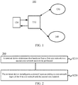
- FIG. 2 schematically shows a schematic flow chart of a network handover method 200 provided by an embodiment of the present application.
- the method 200 may be applied to the wireless communication system 100 described above, but embodiments of the present application are not limited thereto.
- the method 200 includes the following contents.
- a terminal device determines that handover from a first core network to a second core network needs to be performed.
- the first core network i.e., source core network
- the second core network i.e., target core network
- the access network device may communicate with core network devices of the first core network and the second core network, or it may be determined that, the access network to which the terminal device is accessed does not change (or, a serving cell does not change) before and after the terminal device performs the handover.
- the first core network and the second core network may be core networks of a same type, or may be core networks of different types.
- the first core network is a core network of an LTE system, i.e., EPC
- the second core network is a core network of a 5G system
- the first core network is a core network of the 5G system
- the second core network is the EPC, etc., and this is not restricted in embodiments of the present application.
- determining, by the terminal device, that the handover from the first core network to the second core network needs to be performed may refer to as that the terminal device makes the determination by itself, or makes the determination based on a trigger instruction of the network device.
- the network device may be a core network device, or may be an access network device, and the trigger instruction may be an S1 signaling, an N2/N3 signaling, an RRC signaling, etc., and this is not restricted in embodiments of the present application.
- S210 may include: the terminal device determines that the handover from the first core network to the second core network needs to be performed according to a current service requirement.
- the terminal device may determine that, the handover to the second core network supporting the current service requirement needs to be performed.
- the first core network to which the terminal device is currently accessed is the 5GC, and when the terminal device wants to transmit services that are not supported by the 5GC, such as a Multimedia Broadcast and Multicast Service (MBMS), a Vehicle to Vehicle (V2V) service, or a Vehicle to Everything (V2X) service, the terminal device determines that the handover to EPC needs to be performed, to support the current service requirement of the terminal device.
- MBMS Multimedia Broadcast and Multicast Service
- V2V Vehicle to Vehicle
- V2X Vehicle to Everything
- the handover of the terminal device based on the service requirement may occur in core networks of a same type, for example, the first core network is the 5GC and the second core network is also the 5GC, but service types supported by the two core networks are different. If the first core network does not support a first service that the terminal device currently wants to access, and the second core network supports the first service, the terminal device may determine that the handover from the first core network to the second core network needs to be performed.
- the method 200 further includes: the terminal device acquires system information of the second core network.
- the terminal device may receive a broadcast message sent by an access network device and acquires the system information of the second core network from the broadcast message. Or, the terminal device requests to acquire the system information of the second core network by sending an RRC signaling to the access network device.
- the terminal device may acquire a protocol version of a protocol layer (e.g., a protocol version of a PDCP layer, etc.) and configuration information of an RRC layer corresponding to the second core network according to the system information of the second core network.
- the system information of the second core network may be carried in the broadcast message sent by the access network device, and the terminal device may acquire the system information of the second core network by receiving the broadcast message, or the terminal device may acquire the system information of the second core network by sending the RRC signaling to the access network device.
- the terminal device may acquire information of a service type supported by the second core network according to the broadcast message sent by the access network device, such that the terminal device decides to perform handover to which core network the handover.
- S210 may include: When the terminal device has received a trigger instruction from the network device, the terminal device determines that the handover from the first core network to the second core network needs to be performed.
- the trigger instruction is used for notifying the terminal device to perform the handover from the first core network to the second core network.
- the terminal device may perform the network handover based on the trigger instruction of the network device, and the trigger instruction may be used for instructing the terminal device to perform the handover from the first core network to the second core network.
- the trigger instruction may be an S1 signaling, an N2/N3 signaling, an RRC signaling, etc., that is, the terminal device may determine that the handover from the first core network to the second core network needs to be performed according to the trigger instruction, such as the S1 signaling, the N2/N3 signaling, or the RRC signaling, and performs relevant configuration of the protocol layer.
- the trigger instruction of the network device may be sent based on a specific redirection strategy.
- the network device is a core network device, and the core network device may determine that the terminal device needs to perform handover from the first core network to the first core network based on load information of the core network side.
- the network device is an access network device, the access network device may determine that the terminal device needs to perform the handover from the first core network to the first core network based on load information of the access network side.
- the terminal device configures a protocol layer according to core network types of the first core network and the second core network.
- the terminal device may perform relevant configuration of the protocol layer according to whether the core network types of the first core network and the second core network are the same. For example, if the core network types of the first core network and the second core network are the same, that is, before and after the handover is performed, the access network does not change (or a serving cell does not change) and the core network type does not change. In this case, the terminal device does not need to reconfigure a Radio Link Control (RLC) layer, a Media Access Control (MAC) layer, or a Physical (PHY) Layer, while the terminal device does not need to update the protocol versions of the Packet Data Convergence Protocol (PDCP) layer or the Radio Resource Control (RRC) layer. Optionally, the terminal device may need to update some configuration information of the PDCP layer or the RRC layer, such as secret keys.
- RLC Radio Link Control
- MAC Media Access Control
- PHY Physical
- the terminal device does not need to update the protocol versions of the Packet Data Convergence Protocol (PDCP) layer
- the terminal device needs to update a non-access stratum (NAS) entity, and may trigger an interaction between the layers.
- NAS non-access stratum
- the NAS layer needs to notify the RRC layer to reconfigure the configuration of the PDCP layer, and add or delete some configuration of the RRC layer to support a new core network type.
- S220 may include: If the first core network and the second core network are core networks of different types, the terminal device updates configuration of a packet data convergence protocol (PDCP) layer corresponding to the first core network to configuration of a PDCP layer corresponding to the second core network, updates a protocol version of the PDCP layer corresponding to the first core network to a protocol version of the PDCP layer corresponding to the second core network, updates configuration of an RRC layer corresponding to the first core network to configuration of an RRC layer corresponding to the second core network, and switches an NAS entity from a first NAS entity supporting the first core network to a second NAS entity supporting the second core network.
- PDCP packet data convergence protocol
- the terminal device does not need to update the configuration of the RLC layer, the MAC layer, or the PHY layer, but only needs to update some aspects in following.
- the terminal device needs to switch the NAS entity from the first NAS entity corresponding to the first core network to the second NAS entity corresponding to the second core network.
- the terminal device needs to switch an EPC NAS entity to a 5GC NAS entity.
- the terminal device needs to switch the 5GC NAS entity to the EPC NAS entity.
- the terminal device needs to update the protocol version of the PDCP, that is, updating the protocol version of the PDCP layer corresponding to the first core network to the protocol version of the PDCP layer corresponding to the second core network.
- the terminal device may update LTE PDCP to NR PDCP, wherein the LTE PDCP is a protocol version of the PDCP layer corresponding to the first core network and the NR PDCP is a protocol version of the PDCP layer corresponding to the second core network.
- the terminal device updates the NR PDCP to the LTE PDCP, wherein the NR PDCP is the protocol version of the PDCP layer corresponding to the first core network, and the LTE PDCP is the protocol version of the PDCP layer corresponding to the second core network.
- the terminal device needs to reconfigure the PDCP layer, so that the updated configuration of the PDCP layer can be adapted to the second core network.
- the terminal device may update the configuration of the RRC layer.
- the first core network is a core network of a LTE system
- the second core network is a core network of an NR system
- the configuration of the RRC layer of the NR system supports a Service Data Adaptation Layer (SDAP) function and a User Plane (UP) function
- SDAP Service Data Adaptation Layer
- UP User Plane
- the terminal device needs to newly add configuration of the SDAP layer and configuration of the UP function.
- the terminal device needs to delete the configuration of the SDAP layer and the configuration of the UP function.
- the terminal device may only need to reconfigure the PDCP layer and the RRC layer without reconfiguring the RLC layer, MAC layer and PHY layer.
- the terminal device may not need to update the protocol versions of the PDCP layer or the RRC, and may not need to reconfigure the RLC layer, the MAC layer, or the PHY layer, which is beneficial to reducing the signaling overhead of the terminal device during the network handover.
- the method 200 further includes: The terminal device sends an NAS message to the second core network, and the NAS message is used for triggering the second core network to initiate a protocol data unit (PDU) session establishment process.
- PDU protocol data unit
- the terminal device may send the NAS message to the second core network to trigger the second core network to initiate the PDU session establishment process or a PDN connection establishment process.
- the network handover method according to an embodiment of the present application is described in detail from the perspective of a terminal device above in combination with FIG. 2
- a network handover method according to another embodiment of the present application is described in detail from the perspective of a network device below in combination with FIG.3 .
- the description on the network device side corresponds to the description on the terminal device side, and similar descriptions can refer to the above description, which will not be repeated here to avoid repetition.
- FIG. 3 is a schematic flow chart of a network handover method 300 according to another embodiment of the present application.
- the network handover method 300 may be performed by an access network device or a core network device in the communication system shown in FIG. 1 .
- the method 300 includes following contents.
- a network device determines that a terminal device needs to perform handover from a first core network to a second core network.
- the network device sends a trigger instruction to the terminal device, wherein the trigger instruction is used for notifying the terminal device to perform the handover from the first core network to the second core network.
- determining, by the network device, that the terminal device needs to perform the handover from the first core network to the second core network includes: the network device determines that the terminal device needs to perform the handover from the first core network to the second core network according to a current load condition.
- the network device is a core network device of a first core network, and the network device may determine that the terminal device needs to be perform the handover from the first core network to the second core network when the load of the first core network is heavy.
- the network device is an access network device, and the access network device may determine that the terminal device needs to be perform the handover from the first core network to the second core network when the load of the first core network is heavy.
- the access network device may acquire the load condition of the core network to which the connection is established, so that the access network device instructs the terminal device to perform the network handover according to the load condition of the core network.
- the network device is an access network device or a core network device.
- the trigger instruction is an S1 signaling, an N2/N3 signaling, or a radio resource control (RRC) signaling.
- RRC radio resource control
- FIG. 4 and FIG. 5 illustrate embodiments of the present application by taking handover from a core network of an LTE system (i.e. EPC) to a core network of a 5G system (i.e. 5GC) as an example, but embodiments of the present application are not limited thereto.
- a core network currently establishing connection with the terminal device is EPC, i.e. the source core network is the first core network, which is the EPC, and the target core network, i.e. the second core network is 5GC, i.e. the core network type changes before and after the handover is performed, wherein ng-eNB is an access network device shared by the EPC and the 5GC.
- FIG. 4 the terminal device performs the network handover which is triggered by the terminal device
- FIG. 5 the terminal device performs the network handover which is triggered by the network device
- the network device may be a core network device or an access network device.
- a method 20 may include the following contents.
- a terminal device determines that handover from a first core network to a second core network needs to be performed.
- the terminal device may determine that the handover from the first core network to the second core network needs to be performed according to a factor such as a service requirement of the terminal device.
- the terminal device After the terminal device determines that the handover from the first core network to the second core network needs to be performed, further, in S22, the terminal device switches an NAS entity from an EPC NAS entity to a 5GC NAS entity .
- the terminal device may reconfigure a PDCP layer and an RRC layer. Before reconfiguring the PDCP layer and RRC layer, in S23, the terminal device acquires system information of a 5GC. Specifically, the terminal device may acquire the system information of the 5GC from an access network device by receiving a broadcast message or sending an RRC signaling.
- the system information of the 5GC includes a protocol version of the PDCP layer and relevant configuration information of the RRC layer.
- the protocol version of the PDCP layer is a protocol version of the PDCP layer corresponding to the 5GC.
- the process of performing S23 may be before S21 or may be after S21, and this is not restricted in embodiments of the present application.
- the above information needs to be acquired firstly.
- the terminal device updates the protocol version and configuration of the PDCP layer, and newly adds configuration of an SDAP layer and configuration of a UP function (e.g., integrity protection) and the like in the RRC layer.
- a UP function e.g., integrity protection
- the terminal device may send an NAS message to the 5GC to trigger the 5GC to initiate a PDU session establishment process.
- a method 30 may include the following contents.
- the terminal device performs network handover based on a trigger instruction of a network device.
- an EPC determines that the terminal device needs to perform handover from a first core network to a second core network.
- the EPC device may determine that the terminal device needs to perform the handover from the first core network to the second core network according to load information of the EPC device itself.
- the EPC sends a trigger instruction to the terminal device to instruct the terminal device to perform the handover from the first core network to the second core network.
- the trigger instruction is a signaling or a message used for communication between the terminal device and the core network, such as an S1 signaling or an N2/N3 signaling.
- the terminal device performs the network handover based on the trigger of the access network device.
- the ng-eNB determines that the terminal device needs to perform the handover from the first core network to the second core network.
- the ng-eNB may determine that the terminal device needs to perform the handover from the first core network to the second core network according to load information of the ng-eNB itself.
- the ng-eNB sends a trigger instruction to the terminal device to instruct the terminal device to perform the handover from the first core network to the second core network.
- the trigger instruction may be a signaling or a message used for communication between the terminal device and the access network device, such as an RRC signaling, and this is not restricted in embodiments of the present application.
- the terminal device After receiving the trigger instruction of the EPC or the ng-eNB, the terminal device determines that the handover from the first core network to the second core network needs to be performed. Further, in S35, the terminal device switches an NAS entity from an EPC NAS entity to a 5GC NAS entity.
- the terminal device may reconfigure a PDCP layer and an RRC layer. Before reconfiguring the PDCP layer and RRC layer, in S36, the terminal device acquires system information of the 5GC. Specifically, the terminal device may acquire the system information of the 5GC from the access network device by receiving a broadcast message or sending an RRC signaling.
- the system information of the 5GC includes a protocol version of the PDCP layer and relevant configuration information of the RRC layer.
- the protocol version of the PDCP layer is a protocol version of the PDCP layer corresponding to the 5GC.
- the process for performing S36 may be before S31 to S34, or may be after S31 to S34, and this is not restricted in embodiments of the present application.
- the above system information needs to be acquired firstly.
- the terminal device updates the protocol version and configuration of the PDCP layer, and newly adds configuration of an SDAP layer and configuration of a UP function (e.g., integrity protection) and the like in the RRC layer.
- a UP function e.g., integrity protection
- the terminal device may send an NAS message to the 5GC to trigger the 5GC to initiate a PDU session establishment process.
- FIG. 6 shows a block diagram of a terminal device 400 according to an embodiment of the present application.
- the terminal device 400 includes a determination module 410 and a configuration module 420.
- the determination module 410 is used for determining that handover from a first core network to a second core network needs to be performed.
- the configuration module 420 is used for configuring a protocol layer according to core network types of the first core network and the second core network.
- the determination module 410 is specifically used for: determining that the handover from the first core network to the second core network needs to be performed according to a current service requirement.
- the determination module 410 is specifically used for: when a trigger instruction has been received from a network device, determining that the handover from the first core network to the second core network needs to be performed, wherein the trigger instruction is used for notifying the terminal device to perform the handover from the first core network to the second core network.
- the terminal device 400 further includes a first receiving module.
- the first receiving module is used for receiving the trigger instruction sent by the network device.
- the network device is an access network device or a core network device.
- the trigger instruction is an S1 signaling, an N2/N3 signaling, or a radio resource control (RRC) signaling.
- RRC radio resource control
- the terminal device further includes an acquisition module.
- the acquisition module is used for acquiring system information of the second core network.
- the terminal device 400 further includes a second receiving module.
- the second receiving module is used for receiving a broadcast message sent by an access network device and acquiring the system information of the second core network from the broadcast message.
- the terminal device 400 further includes a first sending module and a third receiving module.
- the first sending module is used for sending a first RRC signaling to an access network device.
- the third receiving module is used for receiving a second RRC signaling replied by the access network device.
- the acquisition module is specifically used for: acquiring system information of the second core network from the second RRC signaling.
- the configuration module 420 is specifically used for: If the first core network and the second core network are core networks of different types, updating configuration of a packet data convergence protocol (PDCP) layer corresponding to the first core network to configuration of a PDCP layer corresponding to the second core network, updating a protocol version of the PDCP layer corresponding to the first core network to a protocol version of the PDCP layer corresponding to the second core network, updating configuration of an RRC layer corresponding to the first core network to configuration of an RRC layer corresponding to the second core network, and switching a non-access stratum (NAS) entity from a first NAS entity supporting the first core network to a second NAS entity supporting the second core network.
- PDCP packet data convergence protocol
- RRC non-access stratum
- the configuration module 420 is further used for: not reconfiguring an RLC layer, an MAC layer, or a PHY layer.
- the configuration module 420 is specifically used for: updating LTE PDCP to NR PDCP, and the LTE PDCP is a protocol version of the PDCP layer corresponding to the first core network, and the NR PDCP is a protocol version of the PDCP layer corresponding to the second core network.
- LTE long term evolution
- NR new wireless
- the configuration module 420 is specifically used for: newly adding configuration of a service data adaptation protocol (SDAP) layer and newly adding configuration of a user plane (UP) function, based on the configuration of the RRC layer corresponding to the first core network.
- SDAP service data adaptation protocol
- UP user plane
- the configuration module 420 is specifically used for: updating NR PDCP to LTE PDCP, wherein the NR PDCP is a protocol version of the PDCP layer corresponding to the first core network, and the LTE PDCP is a protocol version of the PDCP layer corresponding to the second core network.
- the configuration module 420 is specifically used for: deleting configuration of an SDAP layer and deleting configuration of a user plane (UP) function, based on the configuration of the RRC layer corresponding to the first core network.
- UP user plane
- the configuration module 420 is specifically used for: if the first core network and the second core network are core networks of the same type, not updating the protocol versions of the PDCP layer or RRC layer of the terminal device.
- the configuration module 420 is specifically used for: updating configuration of the PDCP layer corresponding to the first core network to configuration of the PDCP layer corresponding to the second core network, and/or updating configuration of the RRC layer corresponding to the first core network to configuration of the RRC layer corresponding to the second core network.
- the terminal device 400 further includes a second sending module and a third sending module.
- the second sending module is used for sending a request message to an access network device, and the request message is used for requesting to acquire the configuration of a PDCP layer and the protocol version of the PDCP layer corresponding to the second core network.
- the terminal device 400 further includes a third sending module.
- the third sending module is used for sending an NAS message to the second core network, and the NAS message is used for triggering the second core network to initiate a PDU session establishment process.
- the terminal device 400 in an embodiment of the present application may correspond to the terminal device in the method embodiment of the present application, and the above operations and other operations and/or functions of each unit in the terminal device 400 are respectively for implementing the corresponding flow of the terminal device in the method 200 shown in FIG. 2 , or the method 20 shown in FIG.4 , or the method 30 shown in FIG.5 , and will not be repeated here for brevity.
- FIG.7 shows a block diagram of a network device 500 according to an embodiment of the present application.
- the terminal device 500 includes a determination module 510 and a communication module 520.
- the determination module 510 is used for determining that the terminal device needs to perform handover from a first core network to a second core network.
- the communication module 520 is used for sending a trigger instruction to the terminal device, wherein the trigger instruction is used for notifying the terminal device to perform the handover from the first core network to the second core network.
- the determination module 510 is specifically used for: determining that the terminal device needs to perform the handover from the first core network to the second core network according to a current load condition.
- the network device is an access network device or a core network device.
- the trigger instruction is an S1 signaling, an N2/N3 signaling, or a radio resource control (RRC) signaling.
- RRC radio resource control
- the network device 500 in an embodiment of the present application may correspond to the access network device in the method embodiment of the present application, and the above operations and other operations and/or functions of each unit in the network device 500 are respectively for implementing the corresponding flow of the network device in the method 300 shown in FIG. 3 , or the method 20 shown in FIG.4 , or the method 30 shown in FIG.5 , and will not be repeated here for brevity.
- an embodiment of the present application provides a terminal device 600.
- the terminal device 600 may be the terminal device 400 in FIG. 6 , and can be used to perform the contents for the terminal device corresponding to the method 200 in FIG. 2 , the method 20 in FIG. 4 , or the method 30 in FIG. 5 .
- the terminal device 600 includes an input interface 610, an output interface 620, a processor 630, and a memory 640.
- the input interface 610, the output interface 620, the processor 630, and the memory 640 may be connected through a bus system.
- the memory 640 is used for storing programs, instructions or codes.
- the processor 630 is used for executing the programs, the instructions or the codes in the memory 640 to control the input interface 610 to receive signals, control the output interface 620 to send signals, and accomplish operations in the foregoing method embodiments.
- the processor 630 may be a central processing unit (CPU), or the processor 630 may be other general purpose processor, a digital signal processor (DSP), an application specific integrated circuit (ASIC), an off-the-shelf programmable gate array (FPGA) or other programmable logic device, a discrete gate or a transistor logic device, or a discrete hardware component, etc.
- the general purpose processor may be a microprocessor or the processor may be any conventional processor or the like.
- the memory 640 may include a read-only memory and a random access memory, and provide instructions and data to the processor 630.
- a portion of memory 640 may also include a non-volatile random access memory.
- the memory 640 may also store device type information.
- various contents of the methods described above may be accomplished by integrated logic circuits of hardware in the processor 630 or instructions in the form of software.
- the contents of the method disclosed in connection with an embodiment of the present application can be directly embodied by the execution of the hardware processor or by the execution of the combination of hardware and software modules in the processor.
- the software modules may be located in a storage medium commonly used in the art, such as a random access memory, flash memory, read-only memory, programmable read-only memory or electrically erasable programmable memory, or register.
- the storage medium is located in the memory 640, and the processor 630 reads the information in the memory 640, and accomplishes the contents of the above method in combination with its hardware. In order to avoid repetition, it will not be described in detail here.
- the first receiving module, the second receiving module, the third receiving module, the first sending module, the second sending module and the third sending module in the terminal device 400 shown in FIG.6 may be implemented by the input interface 610 and the output interface 620 shown in FIG. 8
- the determination module 410, the configuration module 420 and the acquisition module in the terminal device 400 shown in FIG.6 may be implemented by the processor 630 shown in FIG. 8 .
- an embodiment of the present application provides a network device 700.
- the network device 700 may be the network device 500 in FIG. 7 , and can be used for perform the contents for the network device corresponding to the method 300 in FIG. 3 , the method 20 in FIG. 4 , or the method 30 in FIG. 5 .
- the network device 700 includes an input interface 710, an output interface 720, a processor 730, and a memory 740.
- the input interface 710, the output interface 720, the processor 730, and the memory 740 may be connected through a bus system.
- the memory 740 is used for storing programs, instructions or codes.
- the processor 730 is used for executing the programs, the instructions or the codes in the memory 740 to control the input interface 710 to receive signals, control the output interface 720 to send signals, and accomplish operations in the foregoing method embodiments.
- the processor 730 may be a central processing unit (CPU), or the processor 730 may be other general purpose processor, a digital signal processor (DSP), an application specific integrated circuit (ASIC), an off-the-shelf programmable gate array(FPGA) or other programmable logic device, a discrete gate or a transistor logic device, or a discrete hardware component, etc.
- the general purpose processor may be a microprocessor or the processor may be any conventional processor or the like.
- the memory 740 may include a read-only memory and a random access memory, and provide instructions and data to the processor 730.
- a portion of memory 740 may also include a non-volatile random access memory.
- the memory 740 may also store device type information.
- various contents of the methods described above may be accomplished by integrated logic circuits of hardware in the processor 730 or instructions in the form of software.
- the contents of the method disclosed in connection with an embodiment of the present application can be directly embodied by the execution of the hardware processor or by the execution of the combination of hardware and software modules in the processor.
- the software modules may be located in a storage medium commonly used in the art, such as a random access memory, flash memory, read-only memory, programmable read-only memory or electrically erasable programmable memory, or register.
- the storage medium is located in the memory 740, and the processor 730 reads the information in the memory 740, and accomplishes the contents of the above method in combination with its hardware. In order to avoid repetition, it will not be described in detail here.
- the communication module 520 in the network device 500 shown in FIG.7 may be implemented by the input interface 710 and the output interface 720 of FIG. 9
- the determination module 510 in the network device 500 may be implemented by the processor 730 of FIG. 9 .
- An embodiment of the present application provides a computer readable storage medium, the computer readable storage medium stores one or more programs including instructions which, when executed by a portable electronic device including multiple application programs, enable the portable electronic device to perform the methods of the embodiments shown in FIGs. 2 to 5 .
- the embodiment of the application provides a computer program, which includes instructions which, when executed by a computer, enable the computer to execute the corresponding flows of the methods of the embodiments shown in FIGs. 2 to 5 .
- the disclosed system, apparatus and method may be implemented in other ways.
- the apparatus embodiments described above are only illustrative, for example, the division of the units is only a logical function division, and there may be other division manners in actual implementation.
- multiple units or components may be combined or integrated into another system, or some features may be ignored or not executed.
- the mutual coupling or direct coupling or communication connection shown or discussed may be indirect coupling or communication connection through some interface, apparatus or unit, and may be electrical, mechanical or in other forms.
- the unit described as a separate component may or may not be physically separated, and the component shown as a unit may or may not be a physical unit, i.e., it may be located in one place or may be distributed over multiple network units. Some or all of the units may be selected according to practical needs to achieve a purpose of the embodiments.
- various functional units in various embodiments of the present application may be integrated in one processing unit, or various units may be physically present separately, or two or more units may be integrated in one unit.
- the functions may be stored in a computer readable storage medium if implemented in a form of software functional units and sold or used as a separate product.
- the technical solution of the present application in essence, or the part contributing to the related art, or the part of the technical solution, may be embodied in the form of a software product stored in a storage medium, including several instructions for causing a computer device (which may be a personal computer, a server, or a network device, etc.) to perform all or part of the acts of the methods described in various embodiments of the present application.
- the aforementioned storage media include U disk, mobile hard disk, read-only memory (ROM), random access memory (RAM), magnetic disk or optical disk, and other media capable of storing program codes.
Landscapes
- Engineering & Computer Science (AREA)
- Computer Networks & Wireless Communication (AREA)
- Signal Processing (AREA)
- Mobile Radio Communication Systems (AREA)
Abstract
Description
- The present application relates to the communication field, and more particularly, to a network handover method, a terminal device, and a network device.
- With development of the 5G technology, a Long Term Evolution (LTE) system will support an Evolved-Universal Terrestrial Radio Access (E-UTRA) system to access to a 5G core network, or accessing, by an LTE system, to the 5G core network is a transitional and mixed deployment scheme from a 4G network to a 5G network.
- In this network, terminal devices in a same LTE cell may only access to an Evolved Packet Core (EPC), or only access to the 5G core network, or may access to the EPC network and the 5G core network simultaneously.
- In some cases, the terminal device needs to perform handover from one core network to another core network, which involves a large number of signaling interaction processes. Therefore, for the terminal device, how to realize core network handover to reduce signaling overhead is an urgent problem to be solved.
- Embodiments of the present application provide a network handover method, a terminal device and a network device, thus signaling overhead can be reduced during a core network handover.
- In a first aspect, a network handover method is provided. The method includes:
- determining, by a terminal device, that handover from a first core network to a second core network needs to be performed; and
- configuring, by the terminal device, a protocol layer according to core network types of the first core network and the second core network.
- In combination with the first aspect, in some implementations of the first aspect, determining, by the terminal device, that the handover from the first core network to the second core network needs to be performed, includes:
determining, by the terminal device, that the handover from the first core network to the second core network needs to be performed according to a current service requirement. - In combination with the first aspect, in some implementations of the first aspect, determining, by the terminal device, that the handover from the first core network to the second core network needs to be performed, includes:
when the terminal device has received a trigger instruction from a network device, determining, by the terminal device, that the handover from the first core network to the second core network needs to be performed, wherein the trigger instruction is used for notifying the terminal device to perform the handover from the first core network to the second core network. - In combination with the first aspect, in some implementations of the first aspect, the method further includes:
receiving, by the terminal device, the trigger instruction sent by the network device. - In combination with the first aspect, in some implementations of the first aspect, the network device is an access network device or a core network device.
- In combination with the first aspect, in some implementations of the first aspect, the trigger instruction is an S1 signaling, an N2/N3 signaling, or a radio resource control (RRC) signaling.
- In combination with the first aspect, in some implementations of the first aspect, if the first core network and the second core network are core networks of different types, the method further includes:
acquiring, by the terminal device, system information of the second core network. - In combination with the first aspect, in some implementations of the first aspect, acquiring, by the terminal device, the system information of the second core network, includes:
receiving, by the terminal device, a broadcast message sent by an access network device; and acquiring the system information of the second core network from the broadcast message. - In combination with the first aspect, in some implementations of the first aspect, acquiring, by the terminal device, the system information of the second core network, includes:
- sending, by the terminal device, a first RRC signaling to an access network device; and
- receiving, by the terminal device, a second RRC signaling replied by the access network device, and acquiring, by the terminal device, the system information of the second core network from the second RRC signaling.
- In combination with the first aspect, in some implementations of the first aspect, configuring, by the terminal device, the protocol layer according to the core network type of the first core network and the core network type of the second core network, includes:
If the first core network and the second core network are core networks of different types, updating, by the terminal device, configuration of a packet data convergence protocol (PDCP) layer corresponding to the first core network to configuration of a PDCP layer corresponding to the second core network; updating, by the terminal device, a protocol version of the PDCP layer corresponding to the first core network to a protocol version of the PDCP layer corresponding to the second core network; updating, by the terminal device, configuration of a radio resource control (RRC) layer corresponding to the first core network to configuration of an RRC layer corresponding to the second core network; and switching, by the terminal device, a non-access stratum (NAS) entity from a first NAS entity supporting the first core network to a second NAS entity supporting the second core network. - In combination with the first aspect, in some implementations of the first aspect, the method further includes:
not reconfiguring, by the terminal device, a radio link control (RLC) layer, a media access control (MAC) layer, or a physical (PHY) layer. - Therefore, in the network handover method of an embodiment of the present application, under the condition that before and after the handover of the terminal device is performed, the access network does not change and the type of the core network changes, the terminal device can only reconfigure the PDCP layer and RRC without reconfiguring the RLC layer, the MAC layer and the PHY layer, which is beneficial to reducing the signaling overhead of the terminal device during the network handover.
- In combination with the first aspect, in some implementations of the first aspect, if the first core network is a core network of a long term evolution (LTE) system and the second core network is a core network of a new wireless (NR) system, updating the protocol version of the PDCP layer corresponding to the first core network to the protocol version of the PDCP layer corresponding to the second core network includes:
updating, by the terminal device, LTE PDCP to NR PDCP, wherein the LTE PDCP is a protocol version of the PDCP layer corresponding to the first core network, and the NR PDCP is a protocol version of the PDCP layer corresponding to the second core network. - In combination with the first aspect, in some implementations of the first aspect, if the first core network is a core network of the LTE system and the second core network is a core network of the NR system, updating the configuration of the RRC layer corresponding to the first core network to the configuration of the RRC layer corresponding to the second core network includes:
newly adding, by the terminal device, configuration of a service data adaptation protocol (SDAP) layer, and newly adding configuration of a user plane (UP) function, based on the configuration of the RRC layer corresponding to the first core network. - In combination with the first aspect, in some implementations of the first aspect, if the first core network is a core network of an NR system and the second core network is a core network of an LTE system, updating the protocol version of the PDCP layer corresponding to the first core network to the protocol version of the PDCP layer corresponding to the second core network includes:
updating, by the terminal device, NR PDCP to LTE PDCP, wherein the NR PDCP is a protocol version of the PDCP layer corresponding to the first core network, and the LTE PDCP is a protocol version of the PDCP layer corresponding to the second core network. - In combination with the first aspect, in some implementations of the first aspect, if the first core network is the core network of then NR system and the second core network is the core network of the LTE system, updating the configuration of the RRC layer corresponding to the first core network to the configuration of the RRC layer corresponding to the second core network includes:
deleting, by the terminal device, configuration of an SDAP layer and configuration of a user plane (UP) function, based on the configuration of the RRC layer corresponding to the first core network. - In combination with the first aspect, in some implementations of the first aspect, configuring, by the terminal device, the protocol layer according to the core network type of the first core network and the core network type of the second core network, includes:
If the first core network and the second core network are core networks of a same type, not updating, by the terminal device, the protocol version of the PDCP layer or the protocol version of the RRC layer of the terminal device. - In combination with the first aspect, in some implementations of the first aspect, configuring, by the terminal device, the protocol layer according to the core network type of the first core network and the core network type of the second core network, includes:
updating configuration of the PDCP layer corresponding to the first core network to configuration of the PDCP layer corresponding to the second core network, and/or updating configuration of the RRC layer corresponding to the first core network to configuration of the RRC layer corresponding to the second core network. - Therefore, in the network handover method of an embodiment of the present application, under the condition that before and after the handover of the terminal device is performed, the access network does not change and the type of the core network does not change, the terminal may not need to update the protocol versions of the PDCP layer or the RRC, and may not need to reconfigure the RLC layer, the MAC layer, or the PHY layer, which is beneficial to reducing the signaling overhead of the terminal device during the network handover.
- In combination with the first aspect, in some implementations of the first aspect, the method further includes:
sending, by the terminal device, a request message to an access network device, wherein the request message is used for requesting to acquire the configuration of the PDCP layer and the protocol version of the PDCP layer corresponding to the second core network. - In combination with the first aspect, in some implementations of the first aspect, the method further includes:
sending, by the terminal device, an NAS message to the second core network, wherein the NAS message is used for triggering the second core network to initiate a protocol data unit (PDU) session establishment process. - In a second aspect, a network handover method is provided. The method includes:
- determining, by a network device, that a terminal device needs to perform handover from a first core network to a second core network; and
- sending, by the network device, a trigger instruction to the terminal device, wherein the trigger instruction is used for notifying the terminal device to perform the handover from the first core network to the second core network.
- In combination with the second aspect, in some implementations of the second aspect, determining, by the network device, that the terminal device needs to perform the handover from the first core network to the second core network, includes:
determining, by the network device, that the terminal device needs to perform the handover from the first core network to the second core network according to a current load condition. - In combination with the second aspect, in some implementations of the second aspect, the network device is an access network device or a core network device.
- In combination with the second aspect, in some implementations of the second aspect, the trigger instruction is an S1 signaling, an N2/N3 signaling, or a radio resource control (RRC) signaling.
- In a third aspect, a terminal device is provided. The terminal device is used for performing the method in the first aspect or any possible implementation of the above first aspect. Specifically, the terminal device includes units used for performing the method in the first aspect or any possible implementation of the above first aspect.
- In a fourth aspect, a network device is provided. The network device is used for performing the method in the second aspect or any possible implementation of the above second aspect. Specifically, the network device includes units used for performing the method in the second aspect or any possible implementation of the above second aspect.
- In a fifth aspect, a terminal device is provided. The terminal device includes a memory, a processor, an input interface, and an output interface. The memory, the processor, the input interface and the output interface are connected through a bus system. The memory is used for storing instructions, and the processor is used for executing the instructions stored in the memory to perform the method in the first aspect or any possible implementation of the above first aspect.
- In a sixth aspect, a network device is provided. The network device includes a memory, a processor, an input interface, and an output interface. The memory, the processor, the input interface and the output interface are connected through a bus system. The memory is used for storing instructions, and the processor is used for executing the instructions stored in the memory to perform the method in the second aspect or any possible implementation of the above second aspect.
- In a seventh aspect, a computer storage medium is provided. The computer storage medium is used for storing computer software instructions for executing the method in the first aspect or any possible implementation of the above first aspect, which includes a program designed for executing the above aspect.
- In an eighth aspect, a computer storage medium is provided. The computer storage medium is used for storing computer software instructions for executing the method in the second aspect or any of the possible implementations of the above second aspect, which includes a program designed for executing the above aspect.
- In a ninth aspect, a computer program product including instructions is provided. The computer program product, when running on a computer, causes the computer to perform the method in the first aspect or any of the possible implementations of the above first aspect.
- In a tenth aspect, a computer program product including instructions is provided. The computer program product, when running on a computer, causes the computer to perform the method in the second aspect or any of the possible implementations of the above second aspect.
-
-
FIG. 1 is a schematic diagram of a communication system according to an embodiment of the present application. -
FIG. 2 is a schematic flow chart of a network handover method according to an embodiment of the present application. -
FIG. 3 is a schematic flow chart of a network handover method according to another embodiment of the present application. -
FIG. 4 is a schematic diagram of interaction in a network handover method according to according to yet another embodiment of the present application. -
FIG. 5 is a schematic diagram of interaction in a network handover method according to according to yet another embodiment of the present application. -
FIG. 6 is a block diagram of a terminal device according to an embodiment of the present application. -
FIG. 7 is a block diagram of a network device according to an embodiment of the present application. -
FIG. 8 is a block diagram of a terminal device according to another embodiment of the present application. -
Fig. 9 is a block diagram of a network device according to another embodiment of the present application. - The technical solutions in embodiments of the present application will be described in the following with reference to drawings in embodiments of the present application.
- It should be understood that, the terms "system" and "network" are often used interchangeably in this document. The term "and/or" in this document is merely an association relationship describing associated objects, indicating that there may be three relationships, for example, a and/or b may indicate three situations: a alone, a and b, or b alone. In addition, the symbol "/" in this document generally indicates that objects before and after the symbol "/" have an "or" relationship.
- The technical solutions of embodiments of the present application may be applied to various communication systems, such as a Long Term Evolution (LTE) system, an LTE Frequency Division Duplex (FDD) system, an LTE Time Division Duplex (TDD), and a future 5G system.
-
FIG. 1 shows awireless communication system 100 applied in an embodiment of the present application. Thewireless communication system 100 may include anaccess network device 110. Theaccess network device 100 may be a device that communicates with a terminal device. Theaccess network device 100 may provide communication coverage for a specific geographic area and may communicate with terminal devices (e.g., UE) located within the coverage area. Optionally, theaccess network device 100 may be an evolutional Node B (eNB or eNodeB) in an LTE system or a radio controller in a Cloud Radio Access Network (CRAN). The network device may be a relay station, an access point, an on-board device, a wearable device, a network-side device in a future 5G network, or a network device in a future evolved Public Land Mobile Network (PLMN), etc. - The
wireless communication system 100 also includes at least oneterminal device 120 located within the coverage area of theaccess network device 110. Theterminal device 120 may be mobile or fixed. Optionally, theterminal device 120 may be referred to as an access terminal, User Equipment (UE), a subscriber unit, a subscriber station, a mobile station, a rover station, a remote station, a remote terminal, a mobile device, a user terminal, a terminal, a wireless communication device, a user agent, or a user device. The access terminal may be a cellular phone, a cordless phone, a session initiation protocol (SIP) phone, a wireless local loop (WLL) station, a personal digital assistant (PDA), a handheld device with a wireless communication function, a computing device or other processing device connected to a wireless modem, an on-board device, a wearable device, a terminal device in a future 5G network, or a terminal device in a future evolved public land mobile network (PLMN), etc. - The
communication system 100 may include at least two core network devices, for example, acore network device 130 and acore network device 140 shown inFIG.1 . Thecore network device 130 and thecore network device 140 may be core networks of a same type or core networks of different types. For example, thecore network device 130 is a core network device of an LTE system, e.g., EPC, and thecore network device 140 may be a core network device of a 5G system, etc. - It should be noted that, in an embodiment of the present application, different core networks may share an access network device, that is, the access network device may communicate with core network devices of different networks.
- Optionally, in embodiments of the present application, the 5G system or network may also be referred to as a New Radio (NR) system or network.
- As mentioned above, in some cases, the terminal device needs to perform handover from a source core network to a target core network. The source core network and the target core network may be core networks of a same type or core networks of different types. For example, the source core network is an EPC and the target core network is a core network of the 5G system (5GC). When handover from the EPC to the 5GC needs to be performed, in the prior art, the terminal device will firstly release a Protocol Data Unit (PDN) connection with the EPC and a source cell, and then establish a PDU session with the 5GC and the target cell. However, if the serving cell does not change before and after the handover is performed, additional signaling overhead may be caused since the terminal device releases an old RRC connection, and establishes a new RRC.
- In view of this, a network handover method is provided in an embodiment of the present application, by which signaling overhead can be reduced during the network handover.
-
FIG. 2 schematically shows a schematic flow chart of anetwork handover method 200 provided by an embodiment of the present application. Themethod 200 may be applied to thewireless communication system 100 described above, but embodiments of the present application are not limited thereto. - As shown in
FIG. 2 , themethod 200 includes the following contents. - In S210, a terminal device determines that handover from a first core network to a second core network needs to be performed.
- It should be noted that, in an embodiment of the present application, the first core network (i.e., source core network) and the second core network (i.e., target core network) share an access network device, that is, the access network device may communicate with core network devices of the first core network and the second core network, or it may be determined that, the access network to which the terminal device is accessed does not change (or, a serving cell does not change) before and after the terminal device performs the handover.
- Optionally, in an embodiment of the present application, the first core network and the second core network may be core networks of a same type, or may be core networks of different types. For example, the first core network is a core network of an LTE system, i.e., EPC, the second core network is a core network of a 5G system, or the first core network is a core network of the 5G system, the second core network is the EPC, etc., and this is not restricted in embodiments of the present application.
- Optionally, determining, by the terminal device, that the handover from the first core network to the second core network needs to be performed, may refer to as that the terminal device makes the determination by itself, or makes the determination based on a trigger instruction of the network device. Here, the network device may be a core network device, or may be an access network device, and the trigger instruction may be an S1 signaling, an N2/N3 signaling, an RRC signaling, etc., and this is not restricted in embodiments of the present application.
- Optionally, as an embodiment, S210 may include: the terminal device determines that the handover from the first core network to the second core network needs to be performed according to a current service requirement.
- Specifically, when the first core network to which the terminal device currently accessed does not support the current service requirement, the terminal device may determine that, the handover to the second core network supporting the current service requirement needs to be performed. For example, the first core network to which the terminal device is currently accessed is the 5GC, and when the terminal device wants to transmit services that are not supported by the 5GC, such as a Multimedia Broadcast and Multicast Service (MBMS), a Vehicle to Vehicle (V2V) service, or a Vehicle to Everything (V2X) service, the terminal device determines that the handover to EPC needs to be performed, to support the current service requirement of the terminal device. Or, the handover of the terminal device based on the service requirement may occur in core networks of a same type, for example, the first core network is the 5GC and the second core network is also the 5GC, but service types supported by the two core networks are different. If the first core network does not support a first service that the terminal device currently wants to access, and the second core network supports the first service, the terminal device may determine that the handover from the first core network to the second core network needs to be performed.
- Optionally, in some embodiments, if core network types of the first core network and the second core network are different, the
method 200 further includes: the terminal device acquires system information of the second core network. - Optionally, the terminal device may receive a broadcast message sent by an access network device and acquires the system information of the second core network from the broadcast message. Or, the terminal device requests to acquire the system information of the second core network by sending an RRC signaling to the access network device. The terminal device may acquire a protocol version of a protocol layer (e.g., a protocol version of a PDCP layer, etc.) and configuration information of an RRC layer corresponding to the second core network according to the system information of the second core network.
- In other words, the system information of the second core network may be carried in the broadcast message sent by the access network device, and the terminal device may acquire the system information of the second core network by receiving the broadcast message, or the terminal device may acquire the system information of the second core network by sending the RRC signaling to the access network device.
- Optionally, the terminal device may acquire information of a service type supported by the second core network according to the broadcast message sent by the access network device, such that the terminal device decides to perform handover to which core network the handover.
- Optionally, as another embodiment, S210 may include:
When the terminal device has received a trigger instruction from the network device, the terminal device determines that the handover from the first core network to the second core network needs to be performed. The trigger instruction is used for notifying the terminal device to perform the handover from the first core network to the second core network. - That is, the terminal device may perform the network handover based on the trigger instruction of the network device, and the trigger instruction may be used for instructing the terminal device to perform the handover from the first core network to the second core network. Optionally, the trigger instruction may be an S1 signaling, an N2/N3 signaling, an RRC signaling, etc., that is, the terminal device may determine that the handover from the first core network to the second core network needs to be performed according to the trigger instruction, such as the S1 signaling, the N2/N3 signaling, or the RRC signaling, and performs relevant configuration of the protocol layer.
- Optionally, the trigger instruction of the network device may be sent based on a specific redirection strategy. For example, the network device is a core network device, and the core network device may determine that the terminal device needs to perform handover from the first core network to the first core network based on load information of the core network side. Optionally, if the network device is an access network device, the access network device may determine that the terminal device needs to perform the handover from the first core network to the first core network based on load information of the access network side.
- In S220, the terminal device configures a protocol layer according to core network types of the first core network and the second core network.
- Optionally, the terminal device may perform relevant configuration of the protocol layer according to whether the core network types of the first core network and the second core network are the same. For example, if the core network types of the first core network and the second core network are the same, that is, before and after the handover is performed, the access network does not change (or a serving cell does not change) and the core network type does not change. In this case, the terminal device does not need to reconfigure a Radio Link Control (RLC) layer, a Media Access Control (MAC) layer, or a Physical (PHY) Layer, while the terminal device does not need to update the protocol versions of the Packet Data Convergence Protocol (PDCP) layer or the Radio Resource Control (RRC) layer. Optionally, the terminal device may need to update some configuration information of the PDCP layer or the RRC layer, such as secret keys.
- Optionally, if the core network types of the first core network and the second core network are different, that is, before and after the handover is performed, the access network does not change (or the serving cell does not change), but the core network type changes, then the terminal device needs to update a non-access stratum (NAS) entity, and may trigger an interaction between the layers. For example, the NAS layer needs to notify the RRC layer to reconfigure the configuration of the PDCP layer, and add or delete some configuration of the RRC layer to support a new core network type. Detailed description will be set forth in the following in combination with specific examples.
- Optionally, in a specific embodiment, S220 may include:
If the first core network and the second core network are core networks of different types, the terminal device updates configuration of a packet data convergence protocol (PDCP) layer corresponding to the first core network to configuration of a PDCP layer corresponding to the second core network, updates a protocol version of the PDCP layer corresponding to the first core network to a protocol version of the PDCP layer corresponding to the second core network, updates configuration of an RRC layer corresponding to the first core network to configuration of an RRC layer corresponding to the second core network, and switches an NAS entity from a first NAS entity supporting the first core network to a second NAS entity supporting the second core network. - Specifically, if the core network types are different before and after the handover is performed, that is, the core network types of the first core network and the second core network are different, the terminal device does not need to update the configuration of the RLC layer, the MAC layer, or the PHY layer, but only needs to update some aspects in following.
- In a first aspect, the terminal device needs to switch the NAS entity from the first NAS entity corresponding to the first core network to the second NAS entity corresponding to the second core network. For example, if the first core network is a core network of an LTE system, the second core network is a core network of a 5G system, the terminal device needs to switch an EPC NAS entity to a 5GC NAS entity. Or, if the first core network is a core network of the 5G system and the second core network is a core network of the LTE system, the terminal device needs to switch the 5GC NAS entity to the EPC NAS entity.
- In a second aspect, the terminal device needs to update the protocol version of the PDCP, that is, updating the protocol version of the PDCP layer corresponding to the first core network to the protocol version of the PDCP layer corresponding to the second core network. For example, if the first core network is a core network of the LTE system and the second core network is a core network of the NR system, the terminal device may update LTE PDCP to NR PDCP, wherein the LTE PDCP is a protocol version of the PDCP layer corresponding to the first core network and the NR PDCP is a protocol version of the PDCP layer corresponding to the second core network. Or, if the first core network is a core network of the NR system, the second core network is a core network of the LTE system, and the terminal device updates the NR PDCP to the LTE PDCP, wherein the NR PDCP is the protocol version of the PDCP layer corresponding to the first core network, and the LTE PDCP is the protocol version of the PDCP layer corresponding to the second core network.
- In a third aspect, the terminal device needs to reconfigure the PDCP layer, so that the updated configuration of the PDCP layer can be adapted to the second core network.
- Optionally, if functions of the configuration of the RRC layer are different before and after the handover is performed, the terminal device may update the configuration of the RRC layer. For example, if the first core network is a core network of a LTE system, the second core network is a core network of an NR system, the configuration of the RRC layer of the NR system supports a Service Data Adaptation Layer (SDAP) function and a User Plane (UP) function , therefore, when the handover from the core network of the LTE system to the core network of the 5G system is performed, the terminal device needs to newly add configuration of the SDAP layer and configuration of the UP function. Conversely, when the handover from the core network of the NR system to the core network of the LTE system is performed, the terminal device needs to delete the configuration of the SDAP layer and the configuration of the UP function.
- Therefore, in the network handover method of an embodiment of the present application, under the condition that, before and after the terminal device performs the handover, the access network of the terminal device does not change and the core network type changes, the terminal device may only need to reconfigure the PDCP layer and the RRC layer without reconfiguring the RLC layer, MAC layer and PHY layer. Under the condition that, before and after the terminal device performs the handover, the access network of the terminal device does not change and the core network type does not change, the terminal device may not need to update the protocol versions of the PDCP layer or the RRC, and may not need to reconfigure the RLC layer, the MAC layer, or the PHY layer, which is beneficial to reducing the signaling overhead of the terminal device during the network handover.
- Optionally, in some embodiments, the
method 200 further includes:
The terminal device sends an NAS message to the second core network, and the NAS message is used for triggering the second core network to initiate a protocol data unit (PDU) session establishment process. - Specifically, after the reconfiguration of the RRC layer is accomplished, the terminal device may send the NAS message to the second core network to trigger the second core network to initiate the PDU session establishment process or a PDN connection establishment process.
- The network handover method according to an embodiment of the present application is described in detail from the perspective of a terminal device above in combination with
FIG. 2 , and a network handover method according to another embodiment of the present application is described in detail from the perspective of a network device below in combination withFIG.3 . It should be understood that the description on the network device side corresponds to the description on the terminal device side, and similar descriptions can refer to the above description, which will not be repeated here to avoid repetition. -
FIG. 3 is a schematic flow chart of anetwork handover method 300 according to another embodiment of the present application. Thenetwork handover method 300 may be performed by an access network device or a core network device in the communication system shown inFIG. 1 . As shown inFIG. 3 , themethod 300 includes following contents. - In S310, a network device determines that a terminal device needs to perform handover from a first core network to a second core network.
- In S320, the network device sends a trigger instruction to the terminal device, wherein the trigger instruction is used for notifying the terminal device to perform the handover from the first core network to the second core network.
- Optionally, in some embodiments, determining, by the network device, that the terminal device needs to perform the handover from the first core network to the second core network, includes: the network device determines that the terminal device needs to perform the handover from the first core network to the second core network according to a current load condition.
- For example, the network device is a core network device of a first core network, and the network device may determine that the terminal device needs to be perform the handover from the first core network to the second core network when the load of the first core network is heavy. Or, the network device is an access network device, and the access network device may determine that the terminal device needs to be perform the handover from the first core network to the second core network when the load of the first core network is heavy. Optionally, the access network device may acquire the load condition of the core network to which the connection is established, so that the access network device instructs the terminal device to perform the network handover according to the load condition of the core network.
- Optionally, in some embodiments, the network device is an access network device or a core network device.
- Optionally, in some embodiments, the trigger instruction is an S1 signaling, an N2/N3 signaling, or a radio resource control (RRC) signaling.
- The method embodiments of the present application are described in detail above from the perspective of terminal device and network device respectively with reference to
FIGs. 2 to 3 . Network handover methods according to embodiments of the present application are described below with reference toFIGs. 4 and5 from the perspective of device interaction. - It should be understood that
FIG. 4 andFIG. 5 illustrate embodiments of the present application by taking handover from a core network of an LTE system (i.e. EPC) to a core network of a 5G system (i.e. 5GC) as an example, but embodiments of the present application are not limited thereto. - In the embodiment, a core network currently establishing connection with the terminal device is EPC, i.e. the source core network is the first core network, which is the EPC, and the target core network, i.e. the second core network is 5GC, i.e. the core network type changes before and after the handover is performed, wherein ng-eNB is an access network device shared by the EPC and the 5GC.
- The difference between
FIG. 4 andFIG. 5 is that, inFIG. 4 , the terminal device performs the network handover which is triggered by the terminal device, inFIG. 5 , the terminal device performs the network handover which is triggered by the network device, and the network device may be a core network device or an access network device. - As shown in
FIG. 4 , amethod 20 may include the following contents. - In S21, a terminal device determines that handover from a first core network to a second core network needs to be performed.
- Optionally, the terminal device may determine that the handover from the first core network to the second core network needs to be performed according to a factor such as a service requirement of the terminal device.
- After the terminal device determines that the handover from the first core network to the second core network needs to be performed, further, in S22, the terminal device switches an NAS entity from an EPC NAS entity to a 5GC NAS entity .
- Further, the terminal device may reconfigure a PDCP layer and an RRC layer. Before reconfiguring the PDCP layer and RRC layer, in S23, the terminal device acquires system information of a 5GC. Specifically, the terminal device may acquire the system information of the 5GC from an access network device by receiving a broadcast message or sending an RRC signaling.
- The system information of the 5GC includes a protocol version of the PDCP layer and relevant configuration information of the RRC layer. The protocol version of the PDCP layer is a protocol version of the PDCP layer corresponding to the 5GC.
- Optionally, the process of performing S23 may be before S21 or may be after S21, and this is not restricted in embodiments of the present application. In a word, before the PDCP layer and the RRC layer is reconfigured, the above information needs to be acquired firstly.
- Further, in S24, the terminal device updates the protocol version and configuration of the PDCP layer, and newly adds configuration of an SDAP layer and configuration of a UP function (e.g., integrity protection) and the like in the RRC layer.
- After accomplishing the configuration the RRC layer, in S25, the terminal device may send an NAS message to the 5GC to trigger the 5GC to initiate a PDU session establishment process.
- Further, in S26, a PDU session between the terminal device, ng-eNB and 5GC is established.
- As shown in
FIG. 5 , amethod 30 may include the following contents. - In an embodiment, the terminal device performs network handover based on a trigger instruction of a network device.
- In S31, an EPC determines that the terminal device needs to perform handover from a first core network to a second core network.
- Optionally, the EPC device may determine that the terminal device needs to perform the handover from the first core network to the second core network according to load information of the EPC device itself.
- Further, in S32, the EPC sends a trigger instruction to the terminal device to instruct the terminal device to perform the handover from the first core network to the second core network.
- Optionally, the trigger instruction is a signaling or a message used for communication between the terminal device and the core network, such as an S1 signaling or an N2/N3 signaling.
- Optionally, the terminal device performs the network handover based on the trigger of the access network device. Specifically, in S33, the ng-eNB determines that the terminal device needs to perform the handover from the first core network to the second core network. For example, the ng-eNB may determine that the terminal device needs to perform the handover from the first core network to the second core network according to load information of the ng-eNB itself.
- Further, in S34, the ng-eNB sends a trigger instruction to the terminal device to instruct the terminal device to perform the handover from the first core network to the second core network. Optionally, the trigger instruction may be a signaling or a message used for communication between the terminal device and the access network device, such as an RRC signaling, and this is not restricted in embodiments of the present application.
- After receiving the trigger instruction of the EPC or the ng-eNB, the terminal device determines that the handover from the first core network to the second core network needs to be performed. Further, in S35, the terminal device switches an NAS entity from an EPC NAS entity to a 5GC NAS entity.
- Further, the terminal device may reconfigure a PDCP layer and an RRC layer. Before reconfiguring the PDCP layer and RRC layer, in S36, the terminal device acquires system information of the 5GC. Specifically, the terminal device may acquire the system information of the 5GC from the access network device by receiving a broadcast message or sending an RRC signaling.
- The system information of the 5GC includes a protocol version of the PDCP layer and relevant configuration information of the RRC layer. Here, the protocol version of the PDCP layer is a protocol version of the PDCP layer corresponding to the 5GC.
- Optionally, the process for performing S36 may be before S31 to S34, or may be after S31 to S34, and this is not restricted in embodiments of the present application. In a word, before the PDCP layer and the RRC layer is reconfigured, the above system information needs to be acquired firstly.
- Further, in S37, the terminal device updates the protocol version and configuration of the PDCP layer, and newly adds configuration of an SDAP layer and configuration of a UP function (e.g., integrity protection) and the like in the RRC layer.
- After completing to configure the RRC layer, in S38, the terminal device may send an NAS message to the 5GC to trigger the 5GC to initiate a PDU session establishment process.
- Further, in S39, a PDU session between the terminal device, ng-eNB and 5GC is established.
- Method embodiments of the present application are described in detail above with reference to
FIGs. 2 to 5 , device embodiments of the present application are described in detail below with reference toFIGs. 6 to 9 . It should be understood that the device embodiments and the method embodiments correspond to each other, and description of the method embodiments may be referred to for similar description of the device embodiments. -
FIG. 6 shows a block diagram of aterminal device 400 according to an embodiment of the present application. As shown inFIG. 6 , theterminal device 400 includes adetermination module 410 and a configuration module 420. - The
determination module 410 is used for determining that handover from a first core network to a second core network needs to be performed. - The configuration module 420 is used for configuring a protocol layer according to core network types of the first core network and the second core network.
- Optionally, in some embodiments, the
determination module 410 is specifically used for:
determining that the handover from the first core network to the second core network needs to be performed according to a current service requirement. - Optionally, in some embodiments, the
determination module 410 is specifically used for:
when a trigger instruction has been received from a network device, determining that the handover from the first core network to the second core network needs to be performed, wherein the trigger instruction is used for notifying the terminal device to perform the handover from the first core network to the second core network. - Optionally, in some embodiments, the
terminal device 400 further includes a first receiving module. The first receiving module is used for receiving the trigger instruction sent by the network device. - Optionally, in some embodiments, the network device is an access network device or a core network device.
- Optionally, in some embodiments, the trigger instruction is an S1 signaling, an N2/N3 signaling, or a radio resource control (RRC) signaling.
- Optionally, in some embodiments, if the first core network and the second core network are core networks of different types, the terminal device further includes an acquisition module. The acquisition module is used for acquiring system information of the second core network.
- Optionally, in some embodiments, the
terminal device 400 further includes a second receiving module. The second receiving module is used for receiving a broadcast message sent by an access network device and acquiring the system information of the second core network from the broadcast message. - Optionally, in some embodiments, the
terminal device 400 further includes a first sending module and a third receiving module. The first sending module is used for sending a first RRC signaling to an access network device. The third receiving module is used for receiving a second RRC signaling replied by the access network device. - The acquisition module is specifically used for: acquiring system information of the second core network from the second RRC signaling.
- Optionally, in some embodiments, the configuration module 420 is specifically used for:
If the first core network and the second core network are core networks of different types, updating configuration of a packet data convergence protocol (PDCP) layer corresponding to the first core network to configuration of a PDCP layer corresponding to the second core network, updating a protocol version of the PDCP layer corresponding to the first core network to a protocol version of the PDCP layer corresponding to the second core network, updating configuration of an RRC layer corresponding to the first core network to configuration of an RRC layer corresponding to the second core network, and switching a non-access stratum (NAS) entity from a first NAS entity supporting the first core network to a second NAS entity supporting the second core network. - Optionally, in some embodiments, the configuration module 420 is further used for: not reconfiguring an RLC layer, an MAC layer, or a PHY layer.
- Optionally, in some embodiments, if the first core network is a core network of a long term evolution (LTE) system and the second core network is a core network of a new wireless (NR) system, the configuration module 420 is specifically used for: updating LTE PDCP to NR PDCP, and the LTE PDCP is a protocol version of the PDCP layer corresponding to the first core network, and the NR PDCP is a protocol version of the PDCP layer corresponding to the second core network.
- Optionally, in some embodiments, if the first core network is a core network of an LTE system and the second core network is a core network of an NR system, the configuration module 420 is specifically used for: newly adding configuration of a service data adaptation protocol (SDAP) layer and newly adding configuration of a user plane (UP) function, based on the configuration of the RRC layer corresponding to the first core network.
- Optionally, in some embodiments, if the first core network is a core network of an NR system and the second core network is a core network of an LTE system, the configuration module 420 is specifically used for: updating NR PDCP to LTE PDCP, wherein the NR PDCP is a protocol version of the PDCP layer corresponding to the first core network, and the LTE PDCP is a protocol version of the PDCP layer corresponding to the second core network.
- Optionally, in some embodiments, if the first core network is a core network of an NR system and the second core network is a core network of an LTE system, the configuration module 420 is specifically used for: deleting configuration of an SDAP layer and deleting configuration of a user plane (UP) function, based on the configuration of the RRC layer corresponding to the first core network.
- Optionally, in some embodiments, the configuration module 420 is specifically used for: if the first core network and the second core network are core networks of the same type, not updating the protocol versions of the PDCP layer or RRC layer of the terminal device.
- Optionally, in some embodiments, the configuration module 420 is specifically used for: updating configuration of the PDCP layer corresponding to the first core network to configuration of the PDCP layer corresponding to the second core network, and/or updating configuration of the RRC layer corresponding to the first core network to configuration of the RRC layer corresponding to the second core network.
- Optionally, in some embodiments, the
terminal device 400 further includes a second sending module and a third sending module. The second sending module is used for sending a request message to an access network device, and the request message is used for requesting to acquire the configuration of a PDCP layer and the protocol version of the PDCP layer corresponding to the second core network. - Optionally, in some embodiments, the
terminal device 400 further includes a third sending module. The third sending module is used for sending an NAS message to the second core network, and the NAS message is used for triggering the second core network to initiate a PDU session establishment process. - It should be understood that, the
terminal device 400 in an embodiment of the present application may correspond to the terminal device in the method embodiment of the present application, and the above operations and other operations and/or functions of each unit in theterminal device 400 are respectively for implementing the corresponding flow of the terminal device in themethod 200 shown inFIG. 2 , or themethod 20 shown inFIG.4 , or themethod 30 shown inFIG.5 , and will not be repeated here for brevity. -
FIG.7 shows a block diagram of anetwork device 500 according to an embodiment of the present application. As shown inFIG. 7 , theterminal device 500 includes adetermination module 510 and a communication module 520. - The
determination module 510 is used for determining that the terminal device needs to perform handover from a first core network to a second core network. - The communication module 520 is used for sending a trigger instruction to the terminal device, wherein the trigger instruction is used for notifying the terminal device to perform the handover from the first core network to the second core network.
- Optionally, in some embodiments, the
determination module 510 is specifically used for:
determining that the terminal device needs to perform the handover from the first core network to the second core network according to a current load condition. - Optionally, in some embodiments, the network device is an access network device or a core network device.
- Optionally, in some embodiments, the trigger instruction is an S1 signaling, an N2/N3 signaling, or a radio resource control (RRC) signaling.
- It should be understood that, the
network device 500 in an embodiment of the present application may correspond to the access network device in the method embodiment of the present application, and the above operations and other operations and/or functions of each unit in thenetwork device 500 are respectively for implementing the corresponding flow of the network device in themethod 300 shown inFIG. 3 , or themethod 20 shown inFIG.4 , or themethod 30 shown inFIG.5 , and will not be repeated here for brevity. - As shown in
FIG. 8 , an embodiment of the present application provides aterminal device 600. Theterminal device 600 may be theterminal device 400 inFIG. 6 , and can be used to perform the contents for the terminal device corresponding to themethod 200 inFIG. 2 , themethod 20 inFIG. 4 , or themethod 30 inFIG. 5 . Theterminal device 600 includes aninput interface 610, anoutput interface 620, aprocessor 630, and amemory 640. Theinput interface 610, theoutput interface 620, theprocessor 630, and thememory 640 may be connected through a bus system. Thememory 640 is used for storing programs, instructions or codes. Theprocessor 630 is used for executing the programs, the instructions or the codes in thememory 640 to control theinput interface 610 to receive signals, control theoutput interface 620 to send signals, and accomplish operations in the foregoing method embodiments. - It should be understood that, in an embodiment of the present application, the
processor 630 may be a central processing unit (CPU), or theprocessor 630 may be other general purpose processor, a digital signal processor (DSP), an application specific integrated circuit (ASIC), an off-the-shelf programmable gate array (FPGA) or other programmable logic device, a discrete gate or a transistor logic device, or a discrete hardware component, etc. The general purpose processor may be a microprocessor or the processor may be any conventional processor or the like. - The
memory 640 may include a read-only memory and a random access memory, and provide instructions and data to theprocessor 630. A portion ofmemory 640 may also include a non-volatile random access memory. For example, thememory 640 may also store device type information. - In the implementation process, various contents of the methods described above may be accomplished by integrated logic circuits of hardware in the
processor 630 or instructions in the form of software. The contents of the method disclosed in connection with an embodiment of the present application can be directly embodied by the execution of the hardware processor or by the execution of the combination of hardware and software modules in the processor. The software modules may be located in a storage medium commonly used in the art, such as a random access memory, flash memory, read-only memory, programmable read-only memory or electrically erasable programmable memory, or register. The storage medium is located in thememory 640, and theprocessor 630 reads the information in thememory 640, and accomplishes the contents of the above method in combination with its hardware. In order to avoid repetition, it will not be described in detail here. - In a specific implementation, the first receiving module, the second receiving module, the third receiving module, the first sending module, the second sending module and the third sending module in the
terminal device 400 shown inFIG.6 may be implemented by theinput interface 610 and theoutput interface 620 shown inFIG. 8 , and thedetermination module 410, the configuration module 420 and the acquisition module in theterminal device 400 shown inFIG.6 may be implemented by theprocessor 630 shown inFIG. 8 . - As shown in
FIG. 9 , an embodiment of the present application provides anetwork device 700. Thenetwork device 700 may be thenetwork device 500 inFIG. 7 , and can be used for perform the contents for the network device corresponding to themethod 300 inFIG. 3 , themethod 20 inFIG. 4 , or themethod 30 inFIG. 5 . Thenetwork device 700 includes aninput interface 710, anoutput interface 720, aprocessor 730, and amemory 740. Theinput interface 710, theoutput interface 720, theprocessor 730, and thememory 740 may be connected through a bus system. Thememory 740 is used for storing programs, instructions or codes. Theprocessor 730 is used for executing the programs, the instructions or the codes in thememory 740 to control theinput interface 710 to receive signals, control theoutput interface 720 to send signals, and accomplish operations in the foregoing method embodiments. - It should be understood that, in an embodiment of the present application, the
processor 730 may be a central processing unit (CPU), or theprocessor 730 may be other general purpose processor, a digital signal processor (DSP), an application specific integrated circuit (ASIC), an off-the-shelf programmable gate array(FPGA) or other programmable logic device, a discrete gate or a transistor logic device, or a discrete hardware component, etc. The general purpose processor may be a microprocessor or the processor may be any conventional processor or the like. - The
memory 740 may include a read-only memory and a random access memory, and provide instructions and data to theprocessor 730. A portion ofmemory 740 may also include a non-volatile random access memory. For example, thememory 740 may also store device type information. - In the implementation process, various contents of the methods described above may be accomplished by integrated logic circuits of hardware in the
processor 730 or instructions in the form of software. The contents of the method disclosed in connection with an embodiment of the present application can be directly embodied by the execution of the hardware processor or by the execution of the combination of hardware and software modules in the processor. The software modules may be located in a storage medium commonly used in the art, such as a random access memory, flash memory, read-only memory, programmable read-only memory or electrically erasable programmable memory, or register. The storage medium is located in thememory 740, and theprocessor 730 reads the information in thememory 740, and accomplishes the contents of the above method in combination with its hardware. In order to avoid repetition, it will not be described in detail here. - In a specific implementation, the communication module 520 in the
network device 500 shown inFIG.7 may be implemented by theinput interface 710 and theoutput interface 720 ofFIG. 9 , and thedetermination module 510 in thenetwork device 500 may be implemented by theprocessor 730 ofFIG. 9 . - An embodiment of the present application provides a computer readable storage medium, the computer readable storage medium stores one or more programs including instructions which, when executed by a portable electronic device including multiple application programs, enable the portable electronic device to perform the methods of the embodiments shown in
FIGs. 2 to 5 . - The embodiment of the application provides a computer program, which includes instructions which, when executed by a computer, enable the computer to execute the corresponding flows of the methods of the embodiments shown in
FIGs. 2 to 5 . - The term "and/or" in this document is merely a description of the association relationship between associated objects, indicating that there may be three kinds of relationships, and for example, A and/or B may represent that A exists alone, A and B exist at the same time, or B exists alone. In addition, the symbol "/" herein generally indicates that objects before and after the symbol are in an "or" relationship.
- It should be understood that in various embodiments of the present application, values of sequence numbers in the above-mentioned process do not imply an order of execution, and an order of execution of each process should be determined by its function and internal logic, and should not constitute any limitation on an implementation process of the embodiment of the present application.
- Those of ordinary skill in the art will recognize that the exemplary elements and algorithm acts described in connection with the embodiments disclosed herein can be implemented in electronic hardware, or a combination of computer software and electronic hardware. Whether these functions are performed in hardware or software depends on the specific application and design constraints of the technical solution. Skilled in the art may use different methods to implement the described functions for each particular application, but such implementation should not be considered to be beyond the scope of the present application.
- Those skilled in the art can clearly understand that for convenience and conciseness of description, corresponding processes in the aforementioned method embodiments may be referred to for the specific working processes of the system, device, and unit described above, which are not repeated here.
- In several embodiments provided by the present application, it should be understood that the disclosed system, apparatus and method may be implemented in other ways. For example, the apparatus embodiments described above are only illustrative, for example, the division of the units is only a logical function division, and there may be other division manners in actual implementation. For example, multiple units or components may be combined or integrated into another system, or some features may be ignored or not executed. On the other hand, the mutual coupling or direct coupling or communication connection shown or discussed may be indirect coupling or communication connection through some interface, apparatus or unit, and may be electrical, mechanical or in other forms.
- The unit described as a separate component may or may not be physically separated, and the component shown as a unit may or may not be a physical unit, i.e., it may be located in one place or may be distributed over multiple network units. Some or all of the units may be selected according to practical needs to achieve a purpose of the embodiments.
- In addition, various functional units in various embodiments of the present application may be integrated in one processing unit, or various units may be physically present separately, or two or more units may be integrated in one unit.
- The functions may be stored in a computer readable storage medium if implemented in a form of software functional units and sold or used as a separate product. Based on this understanding, the technical solution of the present application, in essence, or the part contributing to the related art, or the part of the technical solution, may be embodied in the form of a software product stored in a storage medium, including several instructions for causing a computer device (which may be a personal computer, a server, or a network device, etc.) to perform all or part of the acts of the methods described in various embodiments of the present application. The aforementioned storage media include U disk, mobile hard disk, read-only memory (ROM), random access memory (RAM), magnetic disk or optical disk, and other media capable of storing program codes.
- The foregoing are merely exemplary embodiments of the present application, but the protection scope of the present application is not limited thereto. Any person skilled in the art can easily conceive changes or substitutions within the technical scope disclosed by the present application, which should be included within the protection scope of the present application. Therefore, the protection scope of the present application should be subject to the protection scope of the claims.
Claims (46)
- A network handover method, comprising:determining, by a terminal device, that handover from a first core network to a second core network needs to be performed; andconfiguring, by the terminal device, a protocol layer according to core network types of the first core network and the second core network.
- The method of claim 1, wherein determining, by the terminal device, that the handover from the first core network to the second core network needs to be performed, comprises:
determining, by the terminal device, that the handover from the first core network to the second core network needs to be performed according to a current service requirement. - The method of claim 1, wherein determining, by the terminal device, that the handover from the first core network to the second core network needs to be performed, comprises:
when the terminal device has received a trigger instruction from a network device, determining, by the terminal device, that the handover from the first core network to the second core network needs to be performed, wherein the trigger instruction is used for notifying the terminal device to perform the handover from the first core network to the second core network. - The method of claim 3, wherein the method further comprises:
receiving, by the terminal device, the trigger instruction sent by the network device. - The method of claim 3 or claim 4, wherein the network device is an access network device or a core network device.
- The method of claim 5, wherein, the trigger instruction is an S1 signaling, an N2/N3 signaling, or a radio resource control (RRC) signaling.
- The method of any one of claims 1-6, wherein when the first core network and the second core network are core networks of different types, the method further comprises:
acquiring, by the terminal device, system information of the second core network. - The method of claim 7, wherein acquiring, by the terminal device, the system information of the second core network, comprises:
receiving, by the terminal device, a broadcast message sent by an access network device; and acquiring, by the terminal device, the system information of the second core network from the broadcast message. - The method of claim 7, wherein acquiring, by the terminal device, the system information of the second core network, comprises:sending, by the terminal device, a first RRC signaling to an access network device; andreceiving, by the terminal device, a second RRC signaling replied by the access network device, and acquiring, by the terminal device, the system information of the second core network from the second RRC signaling.
- The method of any one of claims 1-9, wherein configuring, by the terminal device, the protocol layer according to the core network types of the first core network and the second core network, comprises:
when the first core network and the second core network are core networks of different types, updating, by the terminal device, configuration of a packet data convergence protocol (PDCP) layer corresponding to the first core network to configuration of a PDCP layer corresponding to the second core network; updating, by the terminal device, a protocol version of the PDCP layer corresponding to the first core network to a protocol version of the PDCP layer corresponding to the second core network; updating, by the terminal device, configuration of a radio resource control (RRC) layer corresponding to the first core network to configuration of an RRC layer corresponding to the second core network; and switching, by the terminal device, a non-access stratum (NAS) entity from a first NAS entity supporting the first core network to a second NAS entity supporting the second core network. - The method of claim 10, wherein the method further comprises:
not reconfiguring, by the terminal device, a radio link control (RLC) layer, a media access control (MAC) layer, or a physical (PHY) layer. - The method of claim 10 or claim 11, wherein when the first core network is a core network of a long term evolution (LTE) system, the second core network is a core network of a new wireless (NR) system, updating the protocol version of the PDCP layer corresponding to the first core network to the protocol version of the PDCP layer corresponding to the second core network, comprises:
updating, by the terminal device, LTE PDCP to NR PDCP, wherein the LTE PDCP is a protocol version of the PDCP layer corresponding to the first core network, and the NR PDCP is a protocol version of the PDCP layer corresponding to the second core network. - The method of any one of claims 10-12, wherein when the first core network is a core network of an LTE system, the second core network is a core network of an NR system, updating the configuration the RRC layer corresponding to the first core network to the configuration of the RRC layer corresponding to the second core network, comprises:
newly adding, by the terminal device, configuration of a service data adaptation protocol (SDAP) layer, and newly adding configuration of a user plane (UP) function, based on the configuration of the RRC layer corresponding to the first core network. - The method of claim 10 or claim 11, wherein when the first core network is a core network of an NR system and the second core network is a core network of an LTE system, updating the protocol version of the PDCP layer corresponding to the first core network to the protocol version of the PDCP layer corresponding to the second core network, comprises:
updating, by the terminal device, NR PDCP to LTE PDCP, wherein the NR PDCP is a protocol version of the PDCP layer corresponding to the first core network, and the LTE PDCP is a protocol version of the PDCP layer corresponding to the second core network. - The method of claim 14, wherein when the first core network is the core network of the NR system and the second core network is the core network of the LTE system, updating the configuration of the RRC layer corresponding to the first core network to the configuration of the RRC layer corresponding to the second core network, comprises:
deleting, by the terminal device, configuration of a service data adaptation protocol (SDAP) layer and configuration of a user plane (UP) function, based on the configuration of the RRC layer corresponding to the first core network. - The method of any one of claims 1-9, wherein configuring, by the terminal device, the protocol layer according to the core network types of the first core network and the second core network, comprises:
when the first core network and the second core network are core networks of a same type, not updating, by the terminal device, the protocol version of the PDCP layer or the protocol version of the RRC layer of the terminal device. - The method of claim 16, wherein configuring, by the terminal device, the protocol layer according to the core network types of the first core network and the second core network, comprises:
updating configuration of the PDCP layer corresponding to the first core network to configuration of the PDCP layer corresponding to the second core network, and/or updating configuration of the RRC layer corresponding to the first core network to configuration of the RRC layer corresponding to the second core network. - The method of any one of claims 10-15, wherein the method further comprises:
sending, by the terminal device, a request message to an access network device, wherein the request message is used for requesting to acquire the configuration of the PDCP layer and the protocol version of the PDCP layer corresponding to the second core network. - The method of any one of claims 1-18, wherein the method further comprises:
sending, by the terminal device, an NAS message to the second core network, wherein the NAS message is used for triggering the second core network to initiate a protocol data unit (PDU) session establishment process. - A network handover method, comprising:determining, by a network device, that a terminal device needs to perform handover from a first core network to a second core network; andsending, by the network device, a trigger instruction to the terminal device, wherein the trigger instruction is used for notifying the terminal device to perform the handover from the first core network to the second core network.
- The method of claim 20, wherein determining, by the network device, that the terminal device needs to perform the handover from the first core network to the second core network, comprises:
determining, by the network device, that the terminal device needs to perform the handover from the first core network to the second core network according to a current load condition. - The method of claim 20 or claim 21, wherein the network device is an access network device or a core network device.
- The method of claim 22, wherein, the trigger instruction is an S1 signaling, an N2/N3 signaling, or a radio resource control (RRC) signaling.
- A terminal device comprising:a determination module used for determining that handover from a first core network to a second core network needs to be performed; anda configuration module used for configuring a protocol layer according to core network types of the first core network and the second core network.
- The terminal device of claim 24, wherein the determining module is specifically used for:
determining that the handover from the first core network to the second core network needs to be performed according to a current service requirement. - The terminal device of claim 24, wherein the determining module is specifically used for:
when a trigger instruction has been received from a network device, determining that the handover from the first core network to the second core network needs to be performed, wherein the trigger instruction is used for notifying the terminal device to perform the handover from the first core network to the second core network. - The terminal device of claim 26, wherein the terminal device further comprises:
a first receiving module used for receiving the trigger instruction sent by the network device. - The terminal device of claim 26 or claim 27, wherein the network device is an access network device or a core network device.
- The terminal device of claim 28, wherein the trigger instruction is an S1 signaling, an N2/N3 signaling, or a radio resource control (RRC) signaling.
- The terminal device of any one of claims 24-29, wherein when the first core network and the second core network are core networks of different types, the terminal device further comprises:
an acquisition module used for acquiring system information of the second core network. - The terminal device of claim 30, wherein the terminal device further comprises:
a second receiving module used for receiving a broadcast message sent by an access network device and acquiring the system information of the second core network from the broadcast message. - The terminal device of claim 30, wherein the terminal device further comprises:a first sending module used for sending a first RRC signaling to the access network device;a third receiving module used for receiving a second RRC signaling replied by the access network device;wherein, the acquisition module is specifically used for:
acquiring the system information of the second core network from the second RRC signaling. - The terminal device of any one of claims 24-32, wherein the configuration module is specifically used for:
when the first core network and the second core network are core networks of different types, updating configuration of a packet data convergence protocol (PDCP) layer corresponding to the first core network to configuration of a PDCP layer corresponding to the second core network, updating a protocol version of the PDCP layer corresponding to the first core network to a protocol version of the PDCP layer corresponding to the second core network, updating configuration of an RRC layer corresponding to the first core network to configuration of an RRC layer corresponding to the second core network, and switching a non-access stratum (NAS) entity from a first NAS entity supporting the first core network to a second NAS entity supporting the second core network. - The terminal device of claim 33, wherein the configuration module is specifically used for:
not reconfiguring a radio link control (RLC) layer, a media access control (MAC) layer, or a physical (PHY) layer. - The terminal device of claim 33 or claim 34, wherein when the first core network is a core network of a long term evolution (LTE) system and the second core network is a core network of a new wireless (NR) system, the configuration module is specifically used for:
updating LTE PDCP to NR PDCP, wherein the LTE PDCP is a protocol version of the PDCP layer corresponding to the first core network, and the NR PDCP is a protocol version of the PDCP layer corresponding to the second core network. - The terminal device of any one of claims 33-35, wherein when the first core network is a core network of an LTE system, the second core network is a core network of an NR system, the configuration module is specifically used for:
newly adding configuration of a service data adaptation protocol (SDAP) layer and newly adding configuration of a user plane (UP) function, based on the configuration of the RRC layer corresponding to the first core network. - The terminal device of claim 33 or claim 34, wherein when the first core network is a core network of an NR system and the second core network is a core network of an LTE system, the configuration module is specifically used for:
updating NR PDCP to LTE PDCP, wherein the NR PDCP is a protocol version of the PDCP layer corresponding to the first core network, and the LTE PDCP is a protocol version of the PDCP layer corresponding to the second core network. - The terminal device of claim 37, wherein when the first core network is the core network of the NR system and the second core network is the core network of the LTE system, the configuration module is specifically used for:
deleting configuration of a service data adaptation protocol (SDAP) layer and deleting configuration of a user plane (UP) function, based on the configuration of the RRC layer corresponding to the first core network. - The terminal device of any one of claims 24-32, wherein the configuration module is specifically used for:
when the first core network and the second core network are core networks of a same type, not updating the protocol versions of the PDCP layer or RRC layer of the terminal device. - The terminal device of claim 39, wherein the configuration module is specifically used for:
updating configuration of the PDCP layer corresponding to the first core network to configuration of the PDCP layer corresponding to the second core network, and/or updating configuration of the RRC layer corresponding to the first core network to configuration of the RRC layer corresponding to the second core network. - The terminal device of any one of claims 33-38, wherein the terminal device further comprises:
a second sending module used for sending a request message to an access network device, wherein the request message is used for requesting to acquire the configuration of the PDCP layer and the protocol version of the PDCP layer corresponding to the second core network. - The terminal device of any one of claims 24-41, wherein the terminal device further comprises:
a third sending module used for sending an NAS message to the second core network, wherein the NAS message is used for triggering the second core network to initiate a protocol data unit (PDU) session establishment process. - A network device comprising:a determination module, used for determining that a terminal device needs to perform handover from a first core network to a second core network; anda communication module, used for sending a trigger instruction to the terminal device, wherein the trigger instruction is used for notifying the terminal device to perform the handover from the first core network to the second core network.
- The network device of claim 43, wherein the determination module is specifically used for:
determining that the terminal device needs to perform the handover from the first core network to the second core network according to a current load condition. - The network device of claim 43 or claim 44, wherein the network device is an access network device or a core network device.
- The network device of claim 45, wherein the trigger instruction is an S1 signaling, an N2/N3 signaling, or a radio resource control (RRC) signaling.
Applications Claiming Priority (1)
| Application Number | Priority Date | Filing Date | Title |
|---|---|---|---|
| PCT/CN2017/103532 WO2019061039A1 (en) | 2017-09-26 | 2017-09-26 | Network switching method, terminal device, and network device |
Publications (3)
| Publication Number | Publication Date |
|---|---|
| EP3499804A1 true EP3499804A1 (en) | 2019-06-19 |
| EP3499804A4 EP3499804A4 (en) | 2019-09-04 |
| EP3499804B1 EP3499804B1 (en) | 2020-06-10 |
Family
ID=65900287
Family Applications (1)
| Application Number | Title | Priority Date | Filing Date |
|---|---|---|---|
| EP17923980.1A Active EP3499804B1 (en) | 2017-09-26 | 2017-09-26 | Network switching method and terminal device |
Country Status (4)
| Country | Link |
|---|---|
| US (1) | US20190268820A1 (en) |
| EP (1) | EP3499804B1 (en) |
| CN (1) | CN109792396B (en) |
| WO (1) | WO2019061039A1 (en) |
Families Citing this family (7)
| Publication number | Priority date | Publication date | Assignee | Title |
|---|---|---|---|---|
| WO2020166028A1 (en) * | 2019-02-14 | 2020-08-20 | 株式会社Nttドコモ | Network node |
| CN110351804B (en) * | 2019-06-17 | 2021-11-12 | 腾讯科技(深圳)有限公司 | Communication method, communication device, computer readable medium and electronic equipment |
| CN111786847B (en) * | 2020-06-01 | 2022-03-29 | 北京电信技术发展产业协会 | Fifth generation mobile communication terminal consistency test method and system |
| WO2022000496A1 (en) * | 2020-07-03 | 2022-01-06 | 华为技术有限公司 | Communication method and apparatus |
| CN114513757B (en) * | 2020-11-17 | 2024-05-10 | 维沃移动通信有限公司 | Information acquisition method, information indication device, related equipment and storage medium |
| JP7641395B2 (en) * | 2021-03-10 | 2025-03-06 | テレフオンアクチーボラゲット エルエム エリクソン(パブル) | On-Demand SIB Delivery Using SDT |
| US12108300B2 (en) * | 2021-07-15 | 2024-10-01 | At&T Intellectual Property I, L.P. | Intelligent packet core selection |
Family Cites Families (27)
| Publication number | Priority date | Publication date | Assignee | Title |
|---|---|---|---|---|
| US8078171B2 (en) * | 2007-06-15 | 2011-12-13 | Intel Corporation | Handoff of a mobile station from a first to a second type of wireless network |
| CN101867982A (en) * | 2009-04-17 | 2010-10-20 | 中兴通讯股份有限公司 | Method, terminal, network base station, and system for processing terminal service requests |
| CN101925121B (en) * | 2009-06-10 | 2014-03-19 | 中兴通讯股份有限公司 | Packet data convergence protocol reconstruction method and device |
| CN102123457B (en) * | 2010-01-11 | 2016-04-13 | 中兴通讯股份有限公司 | Changing method and terminal |
| CN102892167A (en) * | 2012-09-19 | 2013-01-23 | 邦讯技术股份有限公司 | Method and system for enabling femtocell gateway to support forward switching |
| CN103442399B (en) * | 2013-08-26 | 2016-04-06 | 东莞宇龙通信科技有限公司 | Method for switching network, network switched system and terminal |
| CN105850192B (en) * | 2013-12-27 | 2020-01-14 | 夏普株式会社 | Terminal device, base station device, and method |
| CN104092579B (en) * | 2014-02-12 | 2016-06-08 | 腾讯科技(深圳)有限公司 | The analogy method of network type and device |
| US20150296418A1 (en) * | 2014-04-15 | 2015-10-15 | Nokia Solutions And Networks Oy | Methods and Apparatus for Handover Management of Transfer Control Protocol Proxy Communications |
| EP3132622B1 (en) * | 2014-04-15 | 2019-09-25 | Nokia Solutions and Networks Oy | Interworking with bearer-based system |
| US10219178B2 (en) * | 2014-12-02 | 2019-02-26 | Cisco Technology, Inc. | Channel aggregation using Wi-Fi |
| WO2017039283A1 (en) * | 2015-08-31 | 2017-03-09 | 삼성전자 주식회사 | Method and apparatus for implementing wireless protocol configurable according to services and devices |
| CN105636133A (en) * | 2015-12-30 | 2016-06-01 | 深圳市金立通信设备有限公司 | Configuration method of wireless access points and base station |
| KR102107327B1 (en) * | 2016-01-08 | 2020-05-06 | 닛본 덴끼 가부시끼가이샤 | Radio station system, radio terminal, and method therefor |
| EP4429296A3 (en) * | 2016-08-09 | 2024-12-11 | Samsung Electronics Co., Ltd | Method and apparatus for managing user plane operation in wireless communication system |
| CN107734573B (en) * | 2016-08-12 | 2020-08-07 | 华为技术有限公司 | Switching method, base station and communication system |
| CN106358238A (en) * | 2016-11-24 | 2017-01-25 | 重庆邮电大学 | Data flow distribution method for LTE-A and WLAN based on interconnection technique |
| DK3510814T3 (en) * | 2016-12-29 | 2020-06-02 | Ericsson Telefon Ab L M | Network node and method for configuring PDCP for a wireless device |
| US10448386B2 (en) * | 2017-01-06 | 2019-10-15 | Kt Corporation | Method and apparatus for controlling redundant data transmission |
| WO2018131987A1 (en) * | 2017-01-16 | 2018-07-19 | Samsung Electronics Co., Ltd. | Method and apparatus for processing data in a wireless communication system |
| US10499376B2 (en) * | 2017-06-16 | 2019-12-03 | Kt Corporation | Methods for managing resource based on open interface and apparatuses thereof |
| JP6994439B2 (en) * | 2017-07-20 | 2022-01-14 | 華碩電腦股▲ふん▼有限公司 | Methods and Devices for Providing Quality of Service (QoS) Flows in Wireless Communities |
| US10869353B2 (en) * | 2017-07-23 | 2020-12-15 | Lg Electronics Inc. | Method and apparatus for modifying radio bearer in CU-DU split scenario |
| WO2019019123A1 (en) * | 2017-07-27 | 2019-01-31 | Oppo广东移动通信有限公司 | Reconfiguration method and related product |
| US10708968B2 (en) * | 2017-08-25 | 2020-07-07 | Kt Corporation | Method of controlling mobility of UE and apparatus therefor |
| CN111345066B (en) * | 2017-11-16 | 2022-07-19 | 瑞典爱立信有限公司 | Handling of PDCP version changes |
| US10869223B2 (en) * | 2018-02-13 | 2020-12-15 | Samsung Electronics Co., Ltd. | Method and apparatus for efficient operation upon packet duplication activation and deactivation in next generation wireless communication system |
-
2017
- 2017-09-26 EP EP17923980.1A patent/EP3499804B1/en active Active
- 2017-09-26 US US16/340,844 patent/US20190268820A1/en not_active Abandoned
- 2017-09-26 CN CN201780050353.4A patent/CN109792396B/en active Active
- 2017-09-26 WO PCT/CN2017/103532 patent/WO2019061039A1/en not_active Ceased
Also Published As
| Publication number | Publication date |
|---|---|
| EP3499804A4 (en) | 2019-09-04 |
| CN109792396B (en) | 2020-04-24 |
| US20190268820A1 (en) | 2019-08-29 |
| WO2019061039A1 (en) | 2019-04-04 |
| CN109792396A (en) | 2019-05-21 |
| EP3499804B1 (en) | 2020-06-10 |
Similar Documents
| Publication | Publication Date | Title |
|---|---|---|
| EP3499804B1 (en) | Network switching method and terminal device | |
| JP7483835B2 (en) | Method, apparatus and system for session management | |
| RU2477015C2 (en) | Method to update information on ue capabilities in mobile telecommunication network | |
| CN115209523B (en) | Delaying cellular re-registration during critical conditions | |
| US10856343B2 (en) | Device and method of handling full configuration | |
| EP3534649B1 (en) | Method for configuring frequency priority, terminal device, base station, and core network device | |
| CN112702784A (en) | Enhancements to Radio Access Capability Signaling (RACS) | |
| US11317274B2 (en) | Access and mobility management policy association termination method and apparatus | |
| WO2021022460A1 (en) | Session verification method, electronic device, and storage medium | |
| AU2018331002A1 (en) | Method for configuring anr, terminal device, base station, and core network device | |
| JP7080832B2 (en) | Information transmission method and equipment | |
| AU2017427860A1 (en) | Method for paging, and access network device, terminal device and core network device | |
| CN113412665A (en) | Session setting method, network equipment and user equipment | |
| CN116419429A (en) | Communication method and device | |
| CN111031534A (en) | Wireless communication method and apparatus | |
| CN108810988A (en) | A kind of method and device of message transmission | |
| JP7195346B2 (en) | Communication method, terminal device and network device in vehicle internet | |
| CN110784912B (en) | Management method of session correspondence and terminal equipment | |
| US20250212150A1 (en) | Communication related to communication state | |
| EP3606282A1 (en) | Congestion processing method and device | |
| CN110913437B (en) | Communication method and network element | |
| US12075349B2 (en) | Method and device for communication | |
| EP3873063A1 (en) | Radio communication method, terminal device and network device | |
| JP2022519005A (en) | Data processing methods, equipment and storage media | |
| CN112400304B (en) | Information transmission method and device and network equipment |
Legal Events
| Date | Code | Title | Description |
|---|---|---|---|
| STAA | Information on the status of an ep patent application or granted ep patent |
Free format text: STATUS: UNKNOWN |
|
| STAA | Information on the status of an ep patent application or granted ep patent |
Free format text: STATUS: THE INTERNATIONAL PUBLICATION HAS BEEN MADE |
|
| PUAI | Public reference made under article 153(3) epc to a published international application that has entered the european phase |
Free format text: ORIGINAL CODE: 0009012 |
|
| STAA | Information on the status of an ep patent application or granted ep patent |
Free format text: STATUS: REQUEST FOR EXAMINATION WAS MADE |
|
| 17P | Request for examination filed |
Effective date: 20190313 |
|
| AK | Designated contracting states |
Kind code of ref document: A1 Designated state(s): AL AT BE BG CH CY CZ DE DK EE ES FI FR GB GR HR HU IE IS IT LI LT LU LV MC MK MT NL NO PL PT RO RS SE SI SK SM TR |
|
| AX | Request for extension of the european patent |
Extension state: BA ME |
|
| R17P | Request for examination filed (corrected) |
Effective date: 20190313 |
|
| A4 | Supplementary search report drawn up and despatched |
Effective date: 20190806 |
|
| RIC1 | Information provided on ipc code assigned before grant |
Ipc: H04W 36/12 20090101AFI20190731BHEP Ipc: H04W 48/12 20090101ALN20190731BHEP |
|
| RAP1 | Party data changed (applicant data changed or rights of an application transferred) |
Owner name: GUANGDONG OPPO MOBILE TELECOMMUNICATIONS CORP., LT |
|
| REG | Reference to a national code |
Ref country code: DE Ref legal event code: R079 Ref document number: 602017018115 Country of ref document: DE Free format text: PREVIOUS MAIN CLASS: H04L0012260000 Ipc: H04W0036120000 |
|
| GRAP | Despatch of communication of intention to grant a patent |
Free format text: ORIGINAL CODE: EPIDOSNIGR1 |
|
| STAA | Information on the status of an ep patent application or granted ep patent |
Free format text: STATUS: GRANT OF PATENT IS INTENDED |
|
| RIC1 | Information provided on ipc code assigned before grant |
Ipc: H04W 36/12 20090101AFI20200219BHEP Ipc: H04W 48/12 20090101ALN20200219BHEP |
|
| RIC1 | Information provided on ipc code assigned before grant |
Ipc: H04W 48/12 20090101ALN20200224BHEP Ipc: H04W 36/12 20090101AFI20200224BHEP |
|
| INTG | Intention to grant announced |
Effective date: 20200312 |
|
| GRAS | Grant fee paid |
Free format text: ORIGINAL CODE: EPIDOSNIGR3 |
|
| GRAA | (expected) grant |
Free format text: ORIGINAL CODE: 0009210 |
|
| STAA | Information on the status of an ep patent application or granted ep patent |
Free format text: STATUS: THE PATENT HAS BEEN GRANTED |
|
| DAV | Request for validation of the european patent (deleted) | ||
| DAX | Request for extension of the european patent (deleted) | ||
| AK | Designated contracting states |
Kind code of ref document: B1 Designated state(s): AL AT BE BG CH CY CZ DE DK EE ES FI FR GB GR HR HU IE IS IT LI LT LU LV MC MK MT NL NO PL PT RO RS SE SI SK SM TR |
|
| REG | Reference to a national code |
Ref country code: GB Ref legal event code: FG4D |
|
| REG | Reference to a national code |
Ref country code: CH Ref legal event code: EP Ref country code: AT Ref legal event code: REF Ref document number: 1280160 Country of ref document: AT Kind code of ref document: T Effective date: 20200615 |
|
| REG | Reference to a national code |
Ref country code: DE Ref legal event code: R096 Ref document number: 602017018115 Country of ref document: DE |
|
| REG | Reference to a national code |
Ref country code: IE Ref legal event code: FG4D |
|
| REG | Reference to a national code |
Ref country code: LT Ref legal event code: MG4D |
|
| PG25 | Lapsed in a contracting state [announced via postgrant information from national office to epo] |
Ref country code: LT Free format text: LAPSE BECAUSE OF FAILURE TO SUBMIT A TRANSLATION OF THE DESCRIPTION OR TO PAY THE FEE WITHIN THE PRESCRIBED TIME-LIMIT Effective date: 20200610 Ref country code: FI Free format text: LAPSE BECAUSE OF FAILURE TO SUBMIT A TRANSLATION OF THE DESCRIPTION OR TO PAY THE FEE WITHIN THE PRESCRIBED TIME-LIMIT Effective date: 20200610 Ref country code: SE Free format text: LAPSE BECAUSE OF FAILURE TO SUBMIT A TRANSLATION OF THE DESCRIPTION OR TO PAY THE FEE WITHIN THE PRESCRIBED TIME-LIMIT Effective date: 20200610 Ref country code: GR Free format text: LAPSE BECAUSE OF FAILURE TO SUBMIT A TRANSLATION OF THE DESCRIPTION OR TO PAY THE FEE WITHIN THE PRESCRIBED TIME-LIMIT Effective date: 20200911 Ref country code: NO Free format text: LAPSE BECAUSE OF FAILURE TO SUBMIT A TRANSLATION OF THE DESCRIPTION OR TO PAY THE FEE WITHIN THE PRESCRIBED TIME-LIMIT Effective date: 20200910 |
|
| REG | Reference to a national code |
Ref country code: NL Ref legal event code: MP Effective date: 20200610 |
|
| PG25 | Lapsed in a contracting state [announced via postgrant information from national office to epo] |
Ref country code: RS Free format text: LAPSE BECAUSE OF FAILURE TO SUBMIT A TRANSLATION OF THE DESCRIPTION OR TO PAY THE FEE WITHIN THE PRESCRIBED TIME-LIMIT Effective date: 20200610 Ref country code: HR Free format text: LAPSE BECAUSE OF FAILURE TO SUBMIT A TRANSLATION OF THE DESCRIPTION OR TO PAY THE FEE WITHIN THE PRESCRIBED TIME-LIMIT Effective date: 20200610 Ref country code: BG Free format text: LAPSE BECAUSE OF FAILURE TO SUBMIT A TRANSLATION OF THE DESCRIPTION OR TO PAY THE FEE WITHIN THE PRESCRIBED TIME-LIMIT Effective date: 20200910 Ref country code: LV Free format text: LAPSE BECAUSE OF FAILURE TO SUBMIT A TRANSLATION OF THE DESCRIPTION OR TO PAY THE FEE WITHIN THE PRESCRIBED TIME-LIMIT Effective date: 20200610 |
|
| REG | Reference to a national code |
Ref country code: AT Ref legal event code: MK05 Ref document number: 1280160 Country of ref document: AT Kind code of ref document: T Effective date: 20200610 |
|
| PG25 | Lapsed in a contracting state [announced via postgrant information from national office to epo] |
Ref country code: AL Free format text: LAPSE BECAUSE OF FAILURE TO SUBMIT A TRANSLATION OF THE DESCRIPTION OR TO PAY THE FEE WITHIN THE PRESCRIBED TIME-LIMIT Effective date: 20200610 Ref country code: NL Free format text: LAPSE BECAUSE OF FAILURE TO SUBMIT A TRANSLATION OF THE DESCRIPTION OR TO PAY THE FEE WITHIN THE PRESCRIBED TIME-LIMIT Effective date: 20200610 |
|
| PG25 | Lapsed in a contracting state [announced via postgrant information from national office to epo] |
Ref country code: RO Free format text: LAPSE BECAUSE OF FAILURE TO SUBMIT A TRANSLATION OF THE DESCRIPTION OR TO PAY THE FEE WITHIN THE PRESCRIBED TIME-LIMIT Effective date: 20200610 Ref country code: EE Free format text: LAPSE BECAUSE OF FAILURE TO SUBMIT A TRANSLATION OF THE DESCRIPTION OR TO PAY THE FEE WITHIN THE PRESCRIBED TIME-LIMIT Effective date: 20200610 Ref country code: SM Free format text: LAPSE BECAUSE OF FAILURE TO SUBMIT A TRANSLATION OF THE DESCRIPTION OR TO PAY THE FEE WITHIN THE PRESCRIBED TIME-LIMIT Effective date: 20200610 Ref country code: PT Free format text: LAPSE BECAUSE OF FAILURE TO SUBMIT A TRANSLATION OF THE DESCRIPTION OR TO PAY THE FEE WITHIN THE PRESCRIBED TIME-LIMIT Effective date: 20201012 Ref country code: IT Free format text: LAPSE BECAUSE OF FAILURE TO SUBMIT A TRANSLATION OF THE DESCRIPTION OR TO PAY THE FEE WITHIN THE PRESCRIBED TIME-LIMIT Effective date: 20200610 Ref country code: AT Free format text: LAPSE BECAUSE OF FAILURE TO SUBMIT A TRANSLATION OF THE DESCRIPTION OR TO PAY THE FEE WITHIN THE PRESCRIBED TIME-LIMIT Effective date: 20200610 Ref country code: ES Free format text: LAPSE BECAUSE OF FAILURE TO SUBMIT A TRANSLATION OF THE DESCRIPTION OR TO PAY THE FEE WITHIN THE PRESCRIBED TIME-LIMIT Effective date: 20200610 Ref country code: CZ Free format text: LAPSE BECAUSE OF FAILURE TO SUBMIT A TRANSLATION OF THE DESCRIPTION OR TO PAY THE FEE WITHIN THE PRESCRIBED TIME-LIMIT Effective date: 20200610 |
|
| PG25 | Lapsed in a contracting state [announced via postgrant information from national office to epo] |
Ref country code: SK Free format text: LAPSE BECAUSE OF FAILURE TO SUBMIT A TRANSLATION OF THE DESCRIPTION OR TO PAY THE FEE WITHIN THE PRESCRIBED TIME-LIMIT Effective date: 20200610 Ref country code: PL Free format text: LAPSE BECAUSE OF FAILURE TO SUBMIT A TRANSLATION OF THE DESCRIPTION OR TO PAY THE FEE WITHIN THE PRESCRIBED TIME-LIMIT Effective date: 20200610 Ref country code: IS Free format text: LAPSE BECAUSE OF FAILURE TO SUBMIT A TRANSLATION OF THE DESCRIPTION OR TO PAY THE FEE WITHIN THE PRESCRIBED TIME-LIMIT Effective date: 20201010 |
|
| REG | Reference to a national code |
Ref country code: DE Ref legal event code: R097 Ref document number: 602017018115 Country of ref document: DE |
|
| REG | Reference to a national code |
Ref country code: DE Ref legal event code: R119 Ref document number: 602017018115 Country of ref document: DE |
|
| PLBE | No opposition filed within time limit |
Free format text: ORIGINAL CODE: 0009261 |
|
| STAA | Information on the status of an ep patent application or granted ep patent |
Free format text: STATUS: NO OPPOSITION FILED WITHIN TIME LIMIT |
|
| PG25 | Lapsed in a contracting state [announced via postgrant information from national office to epo] |
Ref country code: DK Free format text: LAPSE BECAUSE OF FAILURE TO SUBMIT A TRANSLATION OF THE DESCRIPTION OR TO PAY THE FEE WITHIN THE PRESCRIBED TIME-LIMIT Effective date: 20200610 |
|
| REG | Reference to a national code |
Ref country code: CH Ref legal event code: PL |
|
| 26N | No opposition filed |
Effective date: 20210311 |
|
| PG25 | Lapsed in a contracting state [announced via postgrant information from national office to epo] |
Ref country code: SI Free format text: LAPSE BECAUSE OF FAILURE TO SUBMIT A TRANSLATION OF THE DESCRIPTION OR TO PAY THE FEE WITHIN THE PRESCRIBED TIME-LIMIT Effective date: 20200610 |
|
| REG | Reference to a national code |
Ref country code: BE Ref legal event code: MM Effective date: 20200930 |
|
| PG25 | Lapsed in a contracting state [announced via postgrant information from national office to epo] |
Ref country code: LU Free format text: LAPSE BECAUSE OF NON-PAYMENT OF DUE FEES Effective date: 20200926 |
|
| PG25 | Lapsed in a contracting state [announced via postgrant information from national office to epo] |
Ref country code: DE Free format text: LAPSE BECAUSE OF NON-PAYMENT OF DUE FEES Effective date: 20210401 Ref country code: FR Free format text: LAPSE BECAUSE OF NON-PAYMENT OF DUE FEES Effective date: 20200930 |
|
| PG25 | Lapsed in a contracting state [announced via postgrant information from national office to epo] |
Ref country code: IE Free format text: LAPSE BECAUSE OF NON-PAYMENT OF DUE FEES Effective date: 20200926 Ref country code: LI Free format text: LAPSE BECAUSE OF NON-PAYMENT OF DUE FEES Effective date: 20200930 Ref country code: CH Free format text: LAPSE BECAUSE OF NON-PAYMENT OF DUE FEES Effective date: 20200930 Ref country code: BE Free format text: LAPSE BECAUSE OF NON-PAYMENT OF DUE FEES Effective date: 20200930 |
|
| PG25 | Lapsed in a contracting state [announced via postgrant information from national office to epo] |
Ref country code: TR Free format text: LAPSE BECAUSE OF FAILURE TO SUBMIT A TRANSLATION OF THE DESCRIPTION OR TO PAY THE FEE WITHIN THE PRESCRIBED TIME-LIMIT Effective date: 20200610 Ref country code: MT Free format text: LAPSE BECAUSE OF FAILURE TO SUBMIT A TRANSLATION OF THE DESCRIPTION OR TO PAY THE FEE WITHIN THE PRESCRIBED TIME-LIMIT Effective date: 20200610 Ref country code: CY Free format text: LAPSE BECAUSE OF FAILURE TO SUBMIT A TRANSLATION OF THE DESCRIPTION OR TO PAY THE FEE WITHIN THE PRESCRIBED TIME-LIMIT Effective date: 20200610 |
|
| PG25 | Lapsed in a contracting state [announced via postgrant information from national office to epo] |
Ref country code: MK Free format text: LAPSE BECAUSE OF FAILURE TO SUBMIT A TRANSLATION OF THE DESCRIPTION OR TO PAY THE FEE WITHIN THE PRESCRIBED TIME-LIMIT Effective date: 20200610 Ref country code: MC Free format text: LAPSE BECAUSE OF FAILURE TO SUBMIT A TRANSLATION OF THE DESCRIPTION OR TO PAY THE FEE WITHIN THE PRESCRIBED TIME-LIMIT Effective date: 20200610 |
|
| PGFP | Annual fee paid to national office [announced via postgrant information from national office to epo] |
Ref country code: GB Payment date: 20220927 Year of fee payment: 6 |
|
| P01 | Opt-out of the competence of the unified patent court (upc) registered |
Effective date: 20230412 |
|
| GBPC | Gb: european patent ceased through non-payment of renewal fee |
Effective date: 20230926 |
|
| PG25 | Lapsed in a contracting state [announced via postgrant information from national office to epo] |
Ref country code: GB Free format text: LAPSE BECAUSE OF NON-PAYMENT OF DUE FEES Effective date: 20230926 |
|
| PG25 | Lapsed in a contracting state [announced via postgrant information from national office to epo] |
Ref country code: GB Free format text: LAPSE BECAUSE OF NON-PAYMENT OF DUE FEES Effective date: 20230926 |