EP3499704A1 - Induced voltage suppression device, motor system, and power conversion system - Google Patents
Induced voltage suppression device, motor system, and power conversion system Download PDFInfo
- Publication number
- EP3499704A1 EP3499704A1 EP17839105.8A EP17839105A EP3499704A1 EP 3499704 A1 EP3499704 A1 EP 3499704A1 EP 17839105 A EP17839105 A EP 17839105A EP 3499704 A1 EP3499704 A1 EP 3499704A1
- Authority
- EP
- European Patent Office
- Prior art keywords
- voltage
- induced voltage
- motor
- circuit
- suppression device
- Prior art date
- Legal status (The legal status is an assumption and is not a legal conclusion. Google has not performed a legal analysis and makes no representation as to the accuracy of the status listed.)
- Withdrawn
Links
Images


Classifications
-
- H—ELECTRICITY
- H02—GENERATION; CONVERSION OR DISTRIBUTION OF ELECTRIC POWER
- H02H—EMERGENCY PROTECTIVE CIRCUIT ARRANGEMENTS
- H02H7/00—Emergency protective circuit arrangements specially adapted for specific types of electric machines or apparatus or for sectionalised protection of cable or line systems, and effecting automatic switching in the event of an undesired change from normal working conditions
- H02H7/10—Emergency protective circuit arrangements specially adapted for specific types of electric machines or apparatus or for sectionalised protection of cable or line systems, and effecting automatic switching in the event of an undesired change from normal working conditions for converters; for rectifiers
- H02H7/12—Emergency protective circuit arrangements specially adapted for specific types of electric machines or apparatus or for sectionalised protection of cable or line systems, and effecting automatic switching in the event of an undesired change from normal working conditions for converters; for rectifiers for static converters or rectifiers
- H02H7/122—Emergency protective circuit arrangements specially adapted for specific types of electric machines or apparatus or for sectionalised protection of cable or line systems, and effecting automatic switching in the event of an undesired change from normal working conditions for converters; for rectifiers for static converters or rectifiers for inverters, i.e. DC/AC converters
-
- H—ELECTRICITY
- H02—GENERATION; CONVERSION OR DISTRIBUTION OF ELECTRIC POWER
- H02M—APPARATUS FOR CONVERSION BETWEEN AC AND AC, BETWEEN AC AND DC, OR BETWEEN DC AND DC, AND FOR USE WITH MAINS OR SIMILAR POWER SUPPLY SYSTEMS; CONVERSION OF DC OR AC INPUT POWER INTO SURGE OUTPUT POWER; CONTROL OR REGULATION THEREOF
- H02M1/00—Details of apparatus for conversion
- H02M1/32—Means for protecting converters other than automatic disconnection
-
- H—ELECTRICITY
- H02—GENERATION; CONVERSION OR DISTRIBUTION OF ELECTRIC POWER
- H02M—APPARATUS FOR CONVERSION BETWEEN AC AND AC, BETWEEN AC AND DC, OR BETWEEN DC AND DC, AND FOR USE WITH MAINS OR SIMILAR POWER SUPPLY SYSTEMS; CONVERSION OF DC OR AC INPUT POWER INTO SURGE OUTPUT POWER; CONTROL OR REGULATION THEREOF
- H02M7/00—Conversion of AC power input into DC power output; Conversion of DC power input into AC power output
- H02M7/02—Conversion of AC power input into DC power output without possibility of reversal
- H02M7/04—Conversion of AC power input into DC power output without possibility of reversal by static converters
- H02M7/12—Conversion of AC power input into DC power output without possibility of reversal by static converters using discharge tubes with control electrode or semiconductor devices with control electrode
- H02M7/21—Conversion of AC power input into DC power output without possibility of reversal by static converters using discharge tubes with control electrode or semiconductor devices with control electrode using devices of a triode or transistor type requiring continuous application of a control signal
- H02M7/217—Conversion of AC power input into DC power output without possibility of reversal by static converters using discharge tubes with control electrode or semiconductor devices with control electrode using devices of a triode or transistor type requiring continuous application of a control signal using semiconductor devices only
- H02M7/219—Conversion of AC power input into DC power output without possibility of reversal by static converters using discharge tubes with control electrode or semiconductor devices with control electrode using devices of a triode or transistor type requiring continuous application of a control signal using semiconductor devices only in a bridge configuration
-
- H—ELECTRICITY
- H02—GENERATION; CONVERSION OR DISTRIBUTION OF ELECTRIC POWER
- H02M—APPARATUS FOR CONVERSION BETWEEN AC AND AC, BETWEEN AC AND DC, OR BETWEEN DC AND DC, AND FOR USE WITH MAINS OR SIMILAR POWER SUPPLY SYSTEMS; CONVERSION OF DC OR AC INPUT POWER INTO SURGE OUTPUT POWER; CONTROL OR REGULATION THEREOF
- H02M7/00—Conversion of AC power input into DC power output; Conversion of DC power input into AC power output
- H02M7/42—Conversion of DC power input into AC power output without possibility of reversal
- H02M7/44—Conversion of DC power input into AC power output without possibility of reversal by static converters
- H02M7/48—Conversion of DC power input into AC power output without possibility of reversal by static converters using discharge tubes with control electrode or semiconductor devices with control electrode
-
- H—ELECTRICITY
- H02—GENERATION; CONVERSION OR DISTRIBUTION OF ELECTRIC POWER
- H02P—CONTROL OR REGULATION OF ELECTRIC MOTORS, ELECTRIC GENERATORS OR DYNAMO-ELECTRIC CONVERTERS; CONTROLLING TRANSFORMERS, REACTORS OR CHOKE COILS
- H02P29/00—Arrangements for regulating or controlling electric motors, appropriate for both AC and DC motors
- H02P29/02—Providing protection against overload without automatic interruption of supply
- H02P29/032—Preventing damage to the motor, e.g. setting individual current limits for different drive conditions
-
- H—ELECTRICITY
- H02—GENERATION; CONVERSION OR DISTRIBUTION OF ELECTRIC POWER
- H02P—CONTROL OR REGULATION OF ELECTRIC MOTORS, ELECTRIC GENERATORS OR DYNAMO-ELECTRIC CONVERTERS; CONTROLLING TRANSFORMERS, REACTORS OR CHOKE COILS
- H02P6/00—Arrangements for controlling synchronous motors or other dynamo-electric motors using electronic commutation dependent on the rotor position; Electronic commutators therefor
- H02P6/12—Monitoring commutation; Providing indication of commutation failure
Definitions
- the present invention relates to an induced voltage suppression device, a motor system, and a power conversion system.
- a motor is used for the field.
- the motor operates up to high rotation using a permanent magnet for the field.
- a motor equipped with such a permanent magnet does not require an exciting current, an induced voltage generated by the field of the permanent magnet increases in proportion to a rotation speed. Because of this phenomenon, when the motor rotates at a high rotation speed equal to or higher than a certain rotation speed, the generated induced voltage exceeds an output voltage of an inverter, and a method of suppressing the output voltage of the inverter by using weak field control by PWM control is used for control at high motor rotation.
- Patent Literature 1 a motor is PWM-driven in a normal state, but when any abnormality occurs in an inverter, by switching a three phase switching element from PWM driving to three-phase short circuit driving, a DC power supply voltage can be suppressed to a predetermined voltage range.
- An induced voltage suppression device is an induced voltage suppression device that operates using an induced voltage of a motor as a drive source.
- the induced voltage suppression device includes a DC voltage source which generates a DC drive voltage based on the induced voltage, a voltage detection circuit which detects the induced voltage, and a short circuit which performs a three-phase short circuit of the motor by using the drive voltage in a case where it is detected by the voltage detection circuit that the induced voltage exceeds a threshold.
- the induced voltage suppression device is electrically connected in parallel to an inverter circuit that drives the motor between the inverter circuit and the motor.
- a motor system includes the induced voltage suppression device according to the first aspect and the motor.
- a power conversion system includes the induced voltage suppression device according to the first aspect and the inverter circuit.
- FIG. 1 is a circuit diagram of a motor control device according to a first embodiment.
- a power converter 1 includes an inverter circuit including six switching elements 11, the switching elements 11 called an upper arm and the switching elements 11 called a lower arm are connected in upper and lower series.
- the inverter circuit connects a winding of a motor 2 serving as a load to connection points of the upper and lower arms.
- the inverter circuit is connected to a battery (not illustrated) via a P terminal and an N terminal which are DC voltage terminals.
- a capacitor C1 is connected between the P terminal and the N terminal to stabilize a DC voltage of the inverter circuit.
- the power converter 1 includes a control unit and a driving unit, although not illustrated.
- a current value from a current sensor (not illustrated) that detects a current supplied to a three-phase (U phase, V phase, W phase) winding of the motor 2 is fed back to the control unit, and the control unit performs current feedback control.
- the driving unit inputs a PWM driving signal to the switching elements 11 according to a driving signal from the control unit and turns on the upper and lower arms of the inverter circuit alternately to control a current flowing through the winding.
- the power converter 1 configured as described above performs power conversion between a direct current on the battery side and a three-phase alternating current on the motor 2 side.
- the motor 2 is connected to the power converter 1 by the three-phase wiring and performs power running and regeneration.
- the power converter 1 and the motor 2 are an integral structure, that is, so-called machine-integrated, a form of wiring is not used, and for example, connection is performed using a connecting member called a bus bar.
- An induced voltage suppression device 3 is electrically connected to the three-phase wiring between the power converter 1 and the motor 2, in parallel to the power converter 1.
- the induced voltage suppression device 3 includes a rectification circuit 31, a DC voltage source 32, a voltage detection circuit 33, and a short circuit 34.
- the rectification circuit 31 is constituted by a three-phase diode bridge circuit and rectifies a three-phase AC voltage which is an induced voltage of the motor 2 into a DC voltage.
- the DC voltage source 32 is constituted by a capacitor C2 and accumulates the DC voltage rectified by the rectification circuit 31 as electric energy and generates a DC drive voltage by using the accumulated DC voltage.
- the induced voltage suppression device 3 operates with the induced voltage of the motor 2 as a drive source.
- the DC voltage source 32 is not limited to the capacitor C2 and may be anything as long as it accumulates electric energy.
- a Zener diode Zd, resistors R1, R2, and R3, and a diode D are connected in series to both ends of the DC voltage source 32. Furthermore, a collector of a transistor Tr is connected between the Zener diode Zd and the resistor R2, and a base of the transistor Tr is connected between the resistor R2 and the resistor R3. An emitter of the transistor Tr is connected to the capacitor C2 via a resistor R4.
- the short circuit 34 includes the transistors T1 to T3 connected to a three-phase wiring, and when the transistor Tr of the voltage detection circuit 33 is turned on, the transistors T1 to T3 are turned on to perform three-phase short-circuit operation to suppress an induced voltage of the motor 2. That is, when it is detected by the voltage detection circuit 33 that the induced voltage exceeds a threshold, the short circuit 34 performs a three-phase short circuit of the motor 2 using a drive voltage from the DC voltage source 32.
- circuit examples of the rectification circuit 31, the DC voltage source 32, the voltage detection circuit 33, and the short circuit 34 are merely examples, and similar functions may be realized by other circuit configurations.
- the induced voltage suppression device 3 is provided separately from the power converter 1, and the induced voltage suppression device 3 secures a DC voltage by an induced voltage of the motor 2 as a drive source in a self-excited manner. Therefore, even when a power source of a control system including the power converter 1 is lost or even when an abnormality occurs in the power converter 1, that is, even when driving of the power converter 1 is stopped, the induced voltage can be suppressed to a desired voltage range. It is also possible to control such that a DC voltage of the power converter 1 does not exceed the upper limit voltage defined by safety standards and the like.
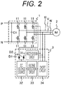
- FIG. 2 is a circuit diagram of a motor control device according to a second embodiment.
- an induced voltage suppression device 3 includes a rectification circuit 31, a DC voltage source 32, a voltage detection circuit 33, and a short circuit 34.
- a voltage from a P terminal of a power converter 1 and a voltage from the rectification circuit 31 are OR-coupled through a diode D1 and a diode D2 respectively and input to the DC voltage source 32.
- a voltage on a higher potential side between a DC voltage from the rectification circuit 31 in the induced voltage suppression device 3 and a DC voltage from the power converter 1 is selected by the diodes D1 and D2 and is applied to the DC voltage source 32.
- the DC voltage source 32 accumulates one of the applied DC voltages and generates a drive voltage as a driving source of the induced voltage suppression device 3. Therefore, the induced voltage suppression device 3 operates normally even if some trouble occurs in one of the DC voltage sources.
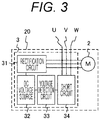
- FIG. 3 is a circuit diagram of a motor system according to a third embodiment.
- an induced voltage suppression device 3 includes a rectification circuit 31, a DC voltage source 32, a voltage detection circuit 33, and a short circuit 34.
- FIG. 3 shows a motor system 20 in which the induced voltage suppression device 3 is integrally incorporated with a motor 2.
- the induced voltage suppression device 3 is integrated with the motor 2 to constitute the motor system 20, for example, by providing the induced voltage suppression device 3 in a three-phase AC terminal box of the motor 2 or a wire end connection portion of a coil end.
- the motor system 20 is provided in a housing enclosing the motor 2, and a three-phase wiring is drawn out from the housing and connected to the power converter 1 (not illustrated).
- an induced voltage can be suppressed to a desired voltage range.
- FIG. 4 is a circuit diagram of a power conversion system according to a fourth embodiment.
- an induced voltage suppression device 3 includes a rectification circuit 31, a DC voltage source 32, a voltage detection circuit 33, and a short circuit 34.
- FIG. 4 illustrates a power conversion system 10 in which the induced voltage suppression device 3 is integrated with a power converter 1.
- the induced voltage suppression device 3 is connected to the three-phase wiring output from the power converter 1 and integrated with the power converter 1 in the power conversion system 10, and a three-phase wiring thereof is connected to a motor 2.
- the induced voltage suppression device 3 is integrated with the power converter 1 in the power conversion system 10, even when the power converter 1 does not have an induced voltage suppression function, an induced voltage can be suppressed to a desired voltage range.
- the power converter 1 has an induced voltage suppression function, even when the power converter 1 fails, an induced voltage can be suppressed to a desired voltage range.
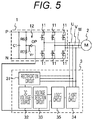
- FIG. 5 is a circuit diagram of a motor control device according to a fifth embodiment.
- an induced voltage suppression device 3 includes a rectification circuit 31, a DC voltage source 32, a voltage detection circuit 33, and a short circuit 34, and further includes a logic circuit 35.
- an overvoltage detection circuit 12 for detecting an overvoltage of a power converter 1 is provided.
- a resistor R6 and a resistor R7 for dividing a voltage between both terminals are provided between a P terminal and an N terminal of the power converter 1, and the divided voltage and a reference voltage Vr are compared by a comparator OP.
- a comparator OP By applying an induced voltage of the motor 2 to the P terminal via a freewheeling diode (not illustrated) provided in parallel with a switching element 11, when a voltage of the P terminal rises, and the power converter 1 becomes overvoltage, an output of the comparator OP is input to the logic circuit 35 of the induced voltage suppression device 3.
- the induced voltage suppression device 3 includes the logic circuit 35 between the voltage detection circuit 33 and the short circuit 34.
- the logic circuit 35 operates the short circuit 34 when a signal from the voltage detection circuit 33 or a signal from the overvoltage detection circuit 12 is input. That is, when an overvoltage of the power converter 1 due to an induced voltage of the motor 2 is detected, the induced voltage suppression device 3 causes the short circuit 34 to perform a three-phase short circuit of the motor 2 in response to detection of the overvoltage. Thereby the induced voltage is suppressed to a desired voltage range.
- the voltage detection circuit 33 of the induced voltage suppression device 3 cannot normally operate due to some abnormality, it is possible to suppress an overvoltage due to an induced voltage by detecting an overvoltage of the power converter 1. In addition, it is possible to suppress the induced voltage even when an abnormality occurs in the power converter 1.
- the induced voltage suppression device 3 for suppressing an induced voltage of the motor 2 has been described. Factors that increase an induced voltage of the motor 2 will be described below.
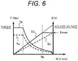
- FIG. 6 is a diagram indicating characteristics of the motor 2.
- the horizontal axis indicates a rotation speed N of the motor 2
- the vertical axis indicates a torque T and an induced voltage E of the motor 2.
- FIG. 6 indicates how the torque T and the induced voltage E change when a magnet amount of the motor 2 is increased for the purpose of increasing a torque of the motor 2.
- a change in the torque T before increasing the magnet amount of the motor 2 is indicated by a broken line Ta, and a change in the induced voltage E is indicated by a broken line Ea.
- the induced voltage E never exceeds an upper limit value Emax defined by the safety standard or the like.
- a change in the torque T after increasing the magnet amount of the motor 2 is indicated by a solid line Tb, and the change in the induced voltage E is indicated by a solid line Eb.
- the torque T rises as indicated by the solid line Tb, but the induced voltage E also rises. Therefore, there is a possibility that the induced voltage E exceeds the upper limit value Emax defined by the safety standard or the like in a high rotation range where the rotation speed N of the motor 2 exceeds a predetermined rotation speed Np.
- a three-phase short circuit is performed such that the induced voltage E is controlled so as not to exceed the upper limit value Emax.
Landscapes
- Engineering & Computer Science (AREA)
- Power Engineering (AREA)
- Inverter Devices (AREA)
- Control Of Electric Motors In General (AREA)
- Control Of Ac Motors In General (AREA)
Abstract
Description
- The present invention relates to an induced voltage suppression device, a motor system, and a power conversion system.
- In recent years, electric vehicles and plug-in hybrid vehicles have become widespread. For these vehicles, a motor is used. The motor operates up to high rotation using a permanent magnet for the field. Although a motor equipped with such a permanent magnet does not require an exciting current, an induced voltage generated by the field of the permanent magnet increases in proportion to a rotation speed. Because of this phenomenon, when the motor rotates at a high rotation speed equal to or higher than a certain rotation speed, the generated induced voltage exceeds an output voltage of an inverter, and a method of suppressing the output voltage of the inverter by using weak field control by PWM control is used for control at high motor rotation.
- In
Patent Literature 1, a motor is PWM-driven in a normal state, but when any abnormality occurs in an inverter, by switching a three phase switching element from PWM driving to three-phase short circuit driving, a DC power supply voltage can be suppressed to a predetermined voltage range. - PTL 1:
JP 2015-198503 A - In the above-described device disclosed in
PTL 1, when a switching element of an inverter does not normally operate due to failure or the like, a three-phase short circuit cannot be performed, and an induced voltage cannot be suppressed. - An induced voltage suppression device according to a first aspect of the present invention is an induced voltage suppression device that operates using an induced voltage of a motor as a drive source. The induced voltage suppression device includes a DC voltage source which generates a DC drive voltage based on the induced voltage, a voltage detection circuit which detects the induced voltage, and a short circuit which performs a three-phase short circuit of the motor by using the drive voltage in a case where it is detected by the voltage detection circuit that the induced voltage exceeds a threshold. The induced voltage suppression device is electrically connected in parallel to an inverter circuit that drives the motor between the inverter circuit and the motor.
- A motor system according to a second aspect of the present invention includes the induced voltage suppression device according to the first aspect and the motor.
- A power conversion system according to a third aspect of the present invention includes the induced voltage suppression device according to the first aspect and the inverter circuit.
- According to the present invention, it is possible to suppress an induced voltage even when an abnormality occurs in an inverter.
-
-
FIG. 1 is a circuit diagram of a motor control device according to a first embodiment. -
FIG. 2 is a circuit diagram of a motor control device according to a second embodiment. -
FIG. 3 is a circuit diagram of a motor system according to a third embodiment. -
FIG. 4 is a circuit diagram of a power conversion system according to a fourth embodiment. -
FIG. 5 is a circuit diagram of a motor control device according to a fifth embodiment. -
FIG. 6 is a diagram indicating characteristics of a motor. -
FIG. 1 is a circuit diagram of a motor control device according to a first embodiment. - A
power converter 1 includes an inverter circuit including sixswitching elements 11, theswitching elements 11 called an upper arm and theswitching elements 11 called a lower arm are connected in upper and lower series. The inverter circuit connects a winding of amotor 2 serving as a load to connection points of the upper and lower arms. The inverter circuit is connected to a battery (not illustrated) via a P terminal and an N terminal which are DC voltage terminals. A capacitor C1 is connected between the P terminal and the N terminal to stabilize a DC voltage of the inverter circuit. - In addition to the inverter circuit, the
power converter 1 includes a control unit and a driving unit, although not illustrated. A current value from a current sensor (not illustrated) that detects a current supplied to a three-phase (U phase, V phase, W phase) winding of themotor 2 is fed back to the control unit, and the control unit performs current feedback control. The driving unit inputs a PWM driving signal to theswitching elements 11 according to a driving signal from the control unit and turns on the upper and lower arms of the inverter circuit alternately to control a current flowing through the winding. Thepower converter 1 configured as described above performs power conversion between a direct current on the battery side and a three-phase alternating current on themotor 2 side. - The
motor 2 is connected to thepower converter 1 by the three-phase wiring and performs power running and regeneration. In the case where thepower converter 1 and themotor 2 are an integral structure, that is, so-called machine-integrated, a form of wiring is not used, and for example, connection is performed using a connecting member called a bus bar. - An induced
voltage suppression device 3 is electrically connected to the three-phase wiring between thepower converter 1 and themotor 2, in parallel to thepower converter 1. The inducedvoltage suppression device 3 includes arectification circuit 31, aDC voltage source 32, avoltage detection circuit 33, and ashort circuit 34. - The
rectification circuit 31 is constituted by a three-phase diode bridge circuit and rectifies a three-phase AC voltage which is an induced voltage of themotor 2 into a DC voltage. TheDC voltage source 32 is constituted by a capacitor C2 and accumulates the DC voltage rectified by therectification circuit 31 as electric energy and generates a DC drive voltage by using the accumulated DC voltage. As a result, the inducedvoltage suppression device 3 operates with the induced voltage of themotor 2 as a drive source. TheDC voltage source 32 is not limited to the capacitor C2 and may be anything as long as it accumulates electric energy. - In the
voltage detection circuit 33, a Zener diode Zd, resistors R1, R2, and R3, and a diode D are connected in series to both ends of theDC voltage source 32. Furthermore, a collector of a transistor Tr is connected between the Zener diode Zd and the resistor R2, and a base of the transistor Tr is connected between the resistor R2 and the resistor R3. An emitter of the transistor Tr is connected to the capacitor C2 via a resistor R4. When a voltage applied to the Zener diode Zd exceeds a breakdown voltage due to the induced voltage of themotor 2 exceeding a predetermined threshold, a current flows, and thevoltage detection circuit 33 detects a voltage by turning on the transistor Tr. - The
short circuit 34 includes the transistors T1 to T3 connected to a three-phase wiring, and when the transistor Tr of thevoltage detection circuit 33 is turned on, the transistors T1 to T3 are turned on to perform three-phase short-circuit operation to suppress an induced voltage of themotor 2. That is, when it is detected by thevoltage detection circuit 33 that the induced voltage exceeds a threshold, theshort circuit 34 performs a three-phase short circuit of themotor 2 using a drive voltage from theDC voltage source 32. - The circuit examples of the
rectification circuit 31, theDC voltage source 32, thevoltage detection circuit 33, and theshort circuit 34 are merely examples, and similar functions may be realized by other circuit configurations. - In the present embodiment, the induced
voltage suppression device 3 is provided separately from thepower converter 1, and the inducedvoltage suppression device 3 secures a DC voltage by an induced voltage of themotor 2 as a drive source in a self-excited manner. Therefore, even when a power source of a control system including thepower converter 1 is lost or even when an abnormality occurs in thepower converter 1, that is, even when driving of thepower converter 1 is stopped, the induced voltage can be suppressed to a desired voltage range. It is also possible to control such that a DC voltage of thepower converter 1 does not exceed the upper limit voltage defined by safety standards and the like. -
FIG. 2 is a circuit diagram of a motor control device according to a second embodiment. InFIG. 2 , the same reference numerals are given to the same parts as those inFIG. 1 described in the first embodiment, and description thereof will be omitted. Similarly toFIG. 1 , an inducedvoltage suppression device 3 includes arectification circuit 31, aDC voltage source 32, avoltage detection circuit 33, and ashort circuit 34. - In
FIG. 2 , a voltage from a P terminal of apower converter 1 and a voltage from therectification circuit 31 are OR-coupled through a diode D1 and a diode D2 respectively and input to theDC voltage source 32. - A voltage on a higher potential side between a DC voltage from the
rectification circuit 31 in the inducedvoltage suppression device 3 and a DC voltage from thepower converter 1 is selected by the diodes D1 and D2 and is applied to theDC voltage source 32. TheDC voltage source 32 accumulates one of the applied DC voltages and generates a drive voltage as a driving source of the inducedvoltage suppression device 3. Therefore, the inducedvoltage suppression device 3 operates normally even if some trouble occurs in one of the DC voltage sources. - In the present embodiment, even if some abnormality occurs in a DC voltage from the
rectification circuit 31 in the inducedvoltage suppression device 3, a drive source of the inducedvoltage suppression device 3 is ensured, and overvoltage due to an induced voltage of themotor 2 can be suppressed. In addition, it is possible to suppress the induced voltage even when an abnormality occurs in thepower converter 1. -
FIG. 3 is a circuit diagram of a motor system according to a third embodiment. InFIG. 3 , the same reference numerals are given to the same parts as those inFIG. 1 described in the first embodiment, and the description thereof will be omitted. Similarly toFIG. 1 , an inducedvoltage suppression device 3 includes arectification circuit 31, aDC voltage source 32, avoltage detection circuit 33, and ashort circuit 34. -
FIG. 3 shows amotor system 20 in which the inducedvoltage suppression device 3 is integrally incorporated with amotor 2. The inducedvoltage suppression device 3 is integrated with themotor 2 to constitute themotor system 20, for example, by providing the inducedvoltage suppression device 3 in a three-phase AC terminal box of themotor 2 or a wire end connection portion of a coil end. Themotor system 20 is provided in a housing enclosing themotor 2, and a three-phase wiring is drawn out from the housing and connected to the power converter 1 (not illustrated). - According to the present embodiment, by incorporating the induced
voltage suppression device 3 in themotor system 20 together with themotor 2, even when the inducedvoltage suppression device 3 is connected to thepower converter 1 having no induced voltage suppression function, an induced voltage can be suppressed to a desired voltage range. In addition, it is possible to suppress an induced voltage even when an abnormality occurs in the connectedpower converter 1. -
FIG. 4 is a circuit diagram of a power conversion system according to a fourth embodiment. InFIG. 4 , the same reference numerals are given to the same parts as those inFIG. 1 described in the first embodiment, and description thereof will be omitted. Similarly toFIG. 1 , an inducedvoltage suppression device 3 includes arectification circuit 31, aDC voltage source 32, avoltage detection circuit 33, and ashort circuit 34. -
FIG. 4 illustrates apower conversion system 10 in which the inducedvoltage suppression device 3 is integrated with apower converter 1. The inducedvoltage suppression device 3 is connected to the three-phase wiring output from thepower converter 1 and integrated with thepower converter 1 in thepower conversion system 10, and a three-phase wiring thereof is connected to amotor 2. - In the present embodiment, since the induced
voltage suppression device 3 is integrated with thepower converter 1 in thepower conversion system 10, even when thepower converter 1 does not have an induced voltage suppression function, an induced voltage can be suppressed to a desired voltage range. In addition, when thepower converter 1 has an induced voltage suppression function, even when thepower converter 1 fails, an induced voltage can be suppressed to a desired voltage range. -
FIG. 5 is a circuit diagram of a motor control device according to a fifth embodiment. InFIG. 5 , the same reference numerals are given to the same parts as those inFIG. 1 described in the first embodiment, and description thereof will be omitted. Similarly toFIG. 1 , an inducedvoltage suppression device 3 includes arectification circuit 31, aDC voltage source 32, avoltage detection circuit 33, and ashort circuit 34, and further includes alogic circuit 35. - In the present embodiment, as illustrated in
FIG. 5 , anovervoltage detection circuit 12 for detecting an overvoltage of apower converter 1 is provided. In theovervoltage detection circuit 12, a resistor R6 and a resistor R7 for dividing a voltage between both terminals are provided between a P terminal and an N terminal of thepower converter 1, and the divided voltage and a reference voltage Vr are compared by a comparator OP. By applying an induced voltage of themotor 2 to the P terminal via a freewheeling diode (not illustrated) provided in parallel with a switchingelement 11, when a voltage of the P terminal rises, and thepower converter 1 becomes overvoltage, an output of the comparator OP is input to thelogic circuit 35 of the inducedvoltage suppression device 3. - The induced
voltage suppression device 3 includes thelogic circuit 35 between thevoltage detection circuit 33 and theshort circuit 34. Thelogic circuit 35 operates theshort circuit 34 when a signal from thevoltage detection circuit 33 or a signal from theovervoltage detection circuit 12 is input. That is, when an overvoltage of thepower converter 1 due to an induced voltage of themotor 2 is detected, the inducedvoltage suppression device 3 causes theshort circuit 34 to perform a three-phase short circuit of themotor 2 in response to detection of the overvoltage. Thereby the induced voltage is suppressed to a desired voltage range. - According to the present embodiment, even if the
voltage detection circuit 33 of the inducedvoltage suppression device 3 cannot normally operate due to some abnormality, it is possible to suppress an overvoltage due to an induced voltage by detecting an overvoltage of thepower converter 1. In addition, it is possible to suppress the induced voltage even when an abnormality occurs in thepower converter 1. - In the first to fifth embodiments described above, the induced
voltage suppression device 3 for suppressing an induced voltage of themotor 2 has been described. Factors that increase an induced voltage of themotor 2 will be described below. -
FIG. 6 is a diagram indicating characteristics of themotor 2. In this figure, the horizontal axis indicates a rotation speed N of themotor 2, and the vertical axis indicates a torque T and an induced voltage E of themotor 2.FIG. 6 indicates how the torque T and the induced voltage E change when a magnet amount of themotor 2 is increased for the purpose of increasing a torque of themotor 2. - In
FIG. 6 , a change in the torque T before increasing the magnet amount of themotor 2 is indicated by a broken line Ta, and a change in the induced voltage E is indicated by a broken line Ea. Before increasing the magnet amount of themotor 2, the induced voltage E never exceeds an upper limit value Emax defined by the safety standard or the like. - In
FIG. 6 , a change in the torque T after increasing the magnet amount of themotor 2 is indicated by a solid line Tb, and the change in the induced voltage E is indicated by a solid line Eb. As the magnet amount is increased, the torque T rises as indicated by the solid line Tb, but the induced voltage E also rises. Therefore, there is a possibility that the induced voltage E exceeds the upper limit value Emax defined by the safety standard or the like in a high rotation range where the rotation speed N of themotor 2 exceeds a predetermined rotation speed Np. In order to suppress this, by the inducedvoltage suppression device 3 described in the first to fifth embodiments above, when the induced voltage E exceeds a threshold, a three-phase short circuit is performed such that the induced voltage E is controlled so as not to exceed the upper limit value Emax. - As described above, according to the first to fifth embodiments, even when the magnet amount is increased for the purpose of increasing the torque T of the
motor 2, an induced voltage can be suppressed to a desired voltage range. - According to the above-described embodiments, the following effects can be obtained.
- (1) The induced
voltage suppression device 3 of the present invention operates using an induced voltage of themotor 2 as a drive source and includes aDC voltage source 32 for generating a DC drive voltage based on the induced voltage of themotor 2, avoltage detection circuit 33 for detecting the induced voltage of themotor 2, and ashort circuit 34 which performs a three-phase short circuit of themotor 2 using the drive voltage from theDC voltage source 32 when it is detected by thevoltage detection circuit 33 that the induced voltage exceeds a threshold. The inducedvoltage suppression device 3 is electrically connected in parallel to an inverter circuit that drives themotor 2 between the inverter circuit and themotor 2. This makes it possible to suppress the induced voltage even when an abnormality occurs in the inverter. - The present invention is not limited to the above-described embodiments. As long as characteristics of the present invention are not impaired, other embodiments envisaged within the scope of technical ideas of the preset invention are included in the scope of the present invention. Further, each of the above-described embodiments may be combined.
-
- 1
- power converter
- 2
- motor
- 3
- induced voltage suppression device
- 11
- switching element
- 31
- rectification circuit
- 32
- DC voltage source
- 33
- voltage detection circuit
- 34
- short circuit
- C1, C2
- capacitor
- Zd
- Zener diode
- R1, R2, R3, R4, R6, R7
- resistance
- D
- diode
- Tr, T1, T2, T3
- transistor
Claims (6)
- An induced voltage suppression device that operates using an induced voltage of a motor as a drive source, the induced voltage suppression device comprising:a DC voltage source configured to generate a DC drive voltage based on the induced voltage;a voltage detection circuit configured to detect the induced voltage; anda short circuit configured to perform a three-phase short circuit of the motor by using the drive voltage in a case where it is detected by the voltage detection circuit that the induced voltage exceeds a threshold,wherein the induced voltage suppression device is electrically connected in parallel to an inverter circuit that drives the motor between the inverter circuit and the motor.
- The induced voltage suppression device according to claim 1, comprising:a rectification circuit configured to rectify an induced voltage of the motor and output a DC voltage,wherein the DC voltage source generates the drive voltage by accumulating a DC voltage from the rectification circuit.
- The induced voltage suppression device according to claim 2, comprising:a selection circuit configured to select either a DC voltage from the rectification circuit or a DC voltage from the inverter circuit,wherein the DC voltage source generates the drive voltage by accumulating a DC voltage selected by the selection circuit.
- The induced voltage suppression device according to any one of claims 1 to 3,
wherein the inverter circuit has an overvoltage detection circuit configured to detect an overvoltage of the inverter circuit by the induced voltage, and
the short circuit performs a three-phase short circuit of the motor in response to detection of the overvoltage by the overvoltage detection circuit. - A motor system, comprising:the induced voltage suppression device according to any one of the claims 1 to 4; andthe motor.
- A power conversion system, comprising:the induced voltage suppression device according to any one of claims 1 to 4; andthe inverter circuit.
Applications Claiming Priority (2)
| Application Number | Priority Date | Filing Date | Title |
|---|---|---|---|
| JP2016156633 | 2016-08-09 | ||
| PCT/JP2017/024426 WO2018030031A1 (en) | 2016-08-09 | 2017-07-04 | Induced voltage suppression device, motor system, and power conversion system |
Publications (2)
| Publication Number | Publication Date |
|---|---|
| EP3499704A1 true EP3499704A1 (en) | 2019-06-19 |
| EP3499704A4 EP3499704A4 (en) | 2020-04-29 |
Family
ID=61161899
Family Applications (1)
| Application Number | Title | Priority Date | Filing Date |
|---|---|---|---|
| EP17839105.8A Withdrawn EP3499704A4 (en) | 2016-08-09 | 2017-07-04 | INDUCED VOLTAGE SUPPRESSION DEVICE, MOTOR SYSTEM, AND POWER CONVERSION SYSTEM |
Country Status (5)
| Country | Link |
|---|---|
| US (1) | US10516332B2 (en) |
| EP (1) | EP3499704A4 (en) |
| JP (1) | JP6629452B2 (en) |
| CN (1) | CN109699198A (en) |
| WO (1) | WO2018030031A1 (en) |
Cited By (1)
| Publication number | Priority date | Publication date | Assignee | Title |
|---|---|---|---|---|
| FR3128069A1 (en) * | 2021-10-13 | 2023-04-14 | Vitesco Technologies | Hybrid Vehicle Inverter Safety Module |
Families Citing this family (2)
| Publication number | Priority date | Publication date | Assignee | Title |
|---|---|---|---|---|
| CN112848900B (en) * | 2019-11-26 | 2024-07-05 | 松下汽车电子系统株式会社 | Vehicle driving device |
| JP7469036B2 (en) * | 2019-12-16 | 2024-04-16 | ファナック株式会社 | Motor drive device having a protection mechanism |
Family Cites Families (16)
| Publication number | Priority date | Publication date | Assignee | Title |
|---|---|---|---|---|
| JP2695959B2 (en) * | 1990-03-05 | 1998-01-14 | 東京電力株式会社 | Control device for winding induction machine |
| JPH08317694A (en) * | 1995-05-19 | 1996-11-29 | Tokyo Electric Power Co Inc:The | Overvoltage protection device |
| KR20040034908A (en) * | 2002-10-17 | 2004-04-29 | 엘지전자 주식회사 | Driving apparatus of three phase induction motor |
| JP3742636B2 (en) * | 2003-08-27 | 2006-02-08 | ファナック株式会社 | Surge voltage suppressor |
| JP2006115667A (en) * | 2004-10-18 | 2006-04-27 | Fuji Electric Fa Components & Systems Co Ltd | Surge voltage suppressor |
| JP4747968B2 (en) * | 2006-06-30 | 2011-08-17 | トヨタ自動車株式会社 | Motor drive device |
| JP5159465B2 (en) * | 2008-06-24 | 2013-03-06 | 株式会社東芝 | Motor control device and semiconductor integrated circuit device |
| JP5276469B2 (en) * | 2009-02-25 | 2013-08-28 | 三菱電機株式会社 | Overvoltage protection device |
| WO2012140840A1 (en) * | 2011-04-14 | 2012-10-18 | パナソニック株式会社 | Converter device and semiconductor device |
| JP2012249397A (en) * | 2011-05-27 | 2012-12-13 | Hitachi Appliances Inc | Motor control device and air conditioner using the same |
| CN103107689A (en) * | 2011-11-11 | 2013-05-15 | 台达电子企业管理(上海)有限公司 | A cascaded frequency converter, power unit and bypass module thereof |
| TWI488421B (en) * | 2013-04-03 | 2015-06-11 | 台達電子工業股份有限公司 | DC to AC power conversion system and operation method thereof |
| WO2015098942A1 (en) * | 2013-12-27 | 2015-07-02 | ダイキン工業株式会社 | Motor driving device |
| JP6158109B2 (en) * | 2014-02-07 | 2017-07-05 | 株式会社東芝 | Overvoltage protection device |
| JP5813167B2 (en) | 2014-04-01 | 2015-11-17 | 三菱電機株式会社 | Inverter fail-safe device |
| US9755501B2 (en) * | 2014-12-10 | 2017-09-05 | Bloom Energy Corporation | Overvoltage snubber for grid tie inverter |
-
2017
- 2017-07-04 EP EP17839105.8A patent/EP3499704A4/en not_active Withdrawn
- 2017-07-04 US US16/316,881 patent/US10516332B2/en not_active Expired - Fee Related
- 2017-07-04 JP JP2018532873A patent/JP6629452B2/en not_active Expired - Fee Related
- 2017-07-04 CN CN201780033416.5A patent/CN109699198A/en active Pending
- 2017-07-04 WO PCT/JP2017/024426 patent/WO2018030031A1/en not_active Ceased
Cited By (3)
| Publication number | Priority date | Publication date | Assignee | Title |
|---|---|---|---|---|
| FR3128069A1 (en) * | 2021-10-13 | 2023-04-14 | Vitesco Technologies | Hybrid Vehicle Inverter Safety Module |
| WO2023061814A1 (en) * | 2021-10-13 | 2023-04-20 | Vitesco Technologies GmbH | Safety module for an inverter of a hybrid vehicle |
| US12499720B2 (en) | 2021-10-13 | 2025-12-16 | Schaeffler Technologies AG & Co. KG | Safety module for an inverter of a hybrid vehicle |
Also Published As
| Publication number | Publication date |
|---|---|
| EP3499704A4 (en) | 2020-04-29 |
| US10516332B2 (en) | 2019-12-24 |
| CN109699198A (en) | 2019-04-30 |
| JP6629452B2 (en) | 2020-01-15 |
| US20190238049A1 (en) | 2019-08-01 |
| WO2018030031A1 (en) | 2018-02-15 |
| JPWO2018030031A1 (en) | 2019-02-28 |
Similar Documents
| Publication | Publication Date | Title |
|---|---|---|
| US8547071B2 (en) | Rotary electric machine improved to carry out load-dump protection | |
| TWI383575B (en) | Winding switch of AC motor and its winding switching system | |
| KR101691460B1 (en) | Control board for on-board motor drive | |
| JP5641448B2 (en) | Rotating electric machine for vehicles | |
| CN108450049B (en) | Power supply conversion device | |
| WO2011118259A1 (en) | Discharge control device | |
| CN103580589B (en) | Rotating electric machine for motor vehicles | |
| EP3051648B1 (en) | Inrush current limiting circuit and power conversion device | |
| JP2015208174A (en) | Power generator for vehicle | |
| JP2013121256A (en) | Power conversion device | |
| US10516332B2 (en) | Induced voltage suppression device, motor system, and power conversion system | |
| CN111130062A (en) | Protection circuit and method of motor driving system and air conditioning equipment | |
| US10374509B2 (en) | Control circuit for power converter | |
| CN103813929B (en) | There is the drive system of the battery operation vehicle of the permanent excited synchronous motor of being powered by current converter | |
| JP6167989B2 (en) | Vehicle generator | |
| JP2013511247A (en) | Inverter | |
| CN110323934A (en) | DC/DC converter | |
| CN114614688A (en) | Protection device for inverter, inverter system, and electric vehicle | |
| US10615682B2 (en) | Electrically driven vehicle inverter device | |
| JP5983485B2 (en) | Alternator and rectifier | |
| JP5962468B2 (en) | Vehicle generator | |
| JP2017005910A (en) | Abnormal current detector | |
| JP2018148710A (en) | Electrical junction box | |
| JP2015070621A (en) | Rectifier and temperature detection method of semiconductor switching element | |
| CN100386940C (en) | Power Systems |
Legal Events
| Date | Code | Title | Description |
|---|---|---|---|
| STAA | Information on the status of an ep patent application or granted ep patent |
Free format text: STATUS: THE INTERNATIONAL PUBLICATION HAS BEEN MADE |
|
| PUAI | Public reference made under article 153(3) epc to a published international application that has entered the european phase |
Free format text: ORIGINAL CODE: 0009012 |
|
| STAA | Information on the status of an ep patent application or granted ep patent |
Free format text: STATUS: REQUEST FOR EXAMINATION WAS MADE |
|
| 17P | Request for examination filed |
Effective date: 20190311 |
|
| AK | Designated contracting states |
Kind code of ref document: A1 Designated state(s): AL AT BE BG CH CY CZ DE DK EE ES FI FR GB GR HR HU IE IS IT LI LT LU LV MC MK MT NL NO PL PT RO RS SE SI SK SM TR |
|
| AX | Request for extension of the european patent |
Extension state: BA ME |
|
| DAV | Request for validation of the european patent (deleted) | ||
| DAX | Request for extension of the european patent (deleted) | ||
| A4 | Supplementary search report drawn up and despatched |
Effective date: 20200330 |
|
| RIC1 | Information provided on ipc code assigned before grant |
Ipc: H02H 7/122 20060101ALI20200324BHEP Ipc: H02P 29/028 20160101ALI20200324BHEP Ipc: H02M 7/48 20070101AFI20200324BHEP Ipc: H02M 1/32 20070101ALI20200324BHEP |
|
| RAP3 | Party data changed (applicant data changed or rights of an application transferred) |
Owner name: HITACHI ASTEMO, LTD. |
|
| STAA | Information on the status of an ep patent application or granted ep patent |
Free format text: STATUS: THE APPLICATION HAS BEEN WITHDRAWN |
|
| 18W | Application withdrawn |
Effective date: 20220707 |