EP3499665A1 - Articulated extension lead for connection to a cable for connector to be connected to at least one cable - Google Patents
Articulated extension lead for connection to a cable for connector to be connected to at least one cable Download PDFInfo
- Publication number
- EP3499665A1 EP3499665A1 EP18211082.5A EP18211082A EP3499665A1 EP 3499665 A1 EP3499665 A1 EP 3499665A1 EP 18211082 A EP18211082 A EP 18211082A EP 3499665 A1 EP3499665 A1 EP 3499665A1
- Authority
- EP
- European Patent Office
- Prior art keywords
- component
- cable
- connector
- extension
- sphere
- Prior art date
- Legal status (The legal status is an assumption and is not a legal conclusion. Google has not performed a legal analysis and makes no representation as to the accuracy of the status listed.)
- Withdrawn
Links
Images


Classifications
-
- H—ELECTRICITY
- H01—ELECTRIC ELEMENTS
- H01R—ELECTRICALLY-CONDUCTIVE CONNECTIONS; STRUCTURAL ASSOCIATIONS OF A PLURALITY OF MUTUALLY-INSULATED ELECTRICAL CONNECTING ELEMENTS; COUPLING DEVICES; CURRENT COLLECTORS
- H01R13/00—Details of coupling devices of the kinds covered by groups H01R12/70 or H01R24/00 - H01R33/00
- H01R13/46—Bases; Cases
- H01R13/52—Dustproof, splashproof, drip-proof, waterproof, or flameproof cases
- H01R13/5219—Sealing means between coupling parts, e.g. interfacial seal
- H01R13/5221—Sealing means between coupling parts, e.g. interfacial seal having cable sealing means
-
- H—ELECTRICITY
- H02—GENERATION; CONVERSION OR DISTRIBUTION OF ELECTRIC POWER
- H02G—INSTALLATION OF ELECTRIC CABLES OR LINES, OR OF COMBINED OPTICAL AND ELECTRIC CABLES OR LINES
- H02G3/00—Installations of electric cables or lines or protective tubing therefor in or on buildings, equivalent structures or vehicles
- H02G3/02—Details
- H02G3/04—Protective tubing or conduits, e.g. cable ladders or cable troughs
- H02G3/0462—Tubings, i.e. having a closed section
- H02G3/0475—Tubings, i.e. having a closed section formed by a succession of articulated units
-
- G—PHYSICS
- G02—OPTICS
- G02B—OPTICAL ELEMENTS, SYSTEMS OR APPARATUS
- G02B6/00—Light guides; Structural details of arrangements comprising light guides and other optical elements, e.g. couplings
- G02B6/44—Mechanical structures for providing tensile strength and external protection for fibres, e.g. optical transmission cables
- G02B6/4401—Optical cables
- G02B6/4429—Means specially adapted for strengthening or protecting the cables
- G02B6/443—Protective covering
-
- G—PHYSICS
- G02—OPTICS
- G02B—OPTICAL ELEMENTS, SYSTEMS OR APPARATUS
- G02B6/00—Light guides; Structural details of arrangements comprising light guides and other optical elements, e.g. couplings
- G02B6/44—Mechanical structures for providing tensile strength and external protection for fibres, e.g. optical transmission cables
- G02B6/4439—Auxiliary devices
- G02B6/4459—Ducts; Conduits; Hollow tubes for air blown fibres
-
- H—ELECTRICITY
- H01—ELECTRIC ELEMENTS
- H01R—ELECTRICALLY-CONDUCTIVE CONNECTIONS; STRUCTURAL ASSOCIATIONS OF A PLURALITY OF MUTUALLY-INSULATED ELECTRICAL CONNECTING ELEMENTS; COUPLING DEVICES; CURRENT COLLECTORS
- H01R13/00—Details of coupling devices of the kinds covered by groups H01R12/70 or H01R24/00 - H01R33/00
- H01R13/46—Bases; Cases
- H01R13/50—Bases; Cases formed as an integral body
-
- H—ELECTRICITY
- H01—ELECTRIC ELEMENTS
- H01R—ELECTRICALLY-CONDUCTIVE CONNECTIONS; STRUCTURAL ASSOCIATIONS OF A PLURALITY OF MUTUALLY-INSULATED ELECTRICAL CONNECTING ELEMENTS; COUPLING DEVICES; CURRENT COLLECTORS
- H01R13/00—Details of coupling devices of the kinds covered by groups H01R12/70 or H01R24/00 - H01R33/00
- H01R13/46—Bases; Cases
- H01R13/502—Bases; Cases composed of different pieces
-
- H—ELECTRICITY
- H01—ELECTRIC ELEMENTS
- H01R—ELECTRICALLY-CONDUCTIVE CONNECTIONS; STRUCTURAL ASSOCIATIONS OF A PLURALITY OF MUTUALLY-INSULATED ELECTRICAL CONNECTING ELEMENTS; COUPLING DEVICES; CURRENT COLLECTORS
- H01R13/00—Details of coupling devices of the kinds covered by groups H01R12/70 or H01R24/00 - H01R33/00
- H01R13/46—Bases; Cases
- H01R13/52—Dustproof, splashproof, drip-proof, waterproof, or flameproof cases
- H01R13/5205—Sealing means between cable and housing, e.g. grommet
-
- H—ELECTRICITY
- H01—ELECTRIC ELEMENTS
- H01R—ELECTRICALLY-CONDUCTIVE CONNECTIONS; STRUCTURAL ASSOCIATIONS OF A PLURALITY OF MUTUALLY-INSULATED ELECTRICAL CONNECTING ELEMENTS; COUPLING DEVICES; CURRENT COLLECTORS
- H01R13/00—Details of coupling devices of the kinds covered by groups H01R12/70 or H01R24/00 - H01R33/00
- H01R13/58—Means for relieving strain on wire connection, e.g. cord grip, for avoiding loosening of connections between wires and terminals within a coupling device terminating a cable
- H01R13/5833—Means for relieving strain on wire connection, e.g. cord grip, for avoiding loosening of connections between wires and terminals within a coupling device terminating a cable the cable being forced in a tortuous or curved path, e.g. knots in cable
-
- H—ELECTRICITY
- H01—ELECTRIC ELEMENTS
- H01R—ELECTRICALLY-CONDUCTIVE CONNECTIONS; STRUCTURAL ASSOCIATIONS OF A PLURALITY OF MUTUALLY-INSULATED ELECTRICAL CONNECTING ELEMENTS; COUPLING DEVICES; CURRENT COLLECTORS
- H01R43/00—Apparatus or processes specially adapted for manufacturing, assembling, maintaining, or repairing of line connectors or current collectors or for joining electric conductors
-
- H—ELECTRICITY
- H02—GENERATION; CONVERSION OR DISTRIBUTION OF ELECTRIC POWER
- H02G—INSTALLATION OF ELECTRIC CABLES OR LINES, OR OF COMBINED OPTICAL AND ELECTRIC CABLES OR LINES
- H02G15/00—Cable fittings
- H02G15/013—Sealing means for cable inlets
-
- H—ELECTRICITY
- H02—GENERATION; CONVERSION OR DISTRIBUTION OF ELECTRIC POWER
- H02G—INSTALLATION OF ELECTRIC CABLES OR LINES, OR OF COMBINED OPTICAL AND ELECTRIC CABLES OR LINES
- H02G3/00—Installations of electric cables or lines or protective tubing therefor in or on buildings, equivalent structures or vehicles
- H02G3/02—Details
- H02G3/06—Joints for connecting lengths of protective tubing or channels, to each other or to casings, e.g. to distribution boxes; Ensuring electrical continuity in the joint
Definitions
- the present invention relates to the field of electrical transmission and / or data connection.
- the present invention aims to deport a cable connection of the rear part of a connector body to which it is usually directly attached.
- This cable connection can be of the stuffing box type, heat-shrinkable or heat-sealing sheath, elastomer sleeve, overmolding for example.
- the invention applies more generally to any type of electrical signal transmission and / or data and / or radio frequency (RF) signals and / or optical signals.
- RF radio frequency
- the invention applies in particular for a connector plug intended to be mounted on at least one cable supporting one or more contacts, and to be connected to a base of a box panel of electronic equipment.
- These contacts can be RJ45 type, power, data, combined or optical. These contacts may in particular be an optoelectronic converter interface type SFP / SFP + / QSFP / QSFP +, or optical contacts.
- the cards concerned in particular are those for connection to the bases of electronic equipment which implement several optical and / or electrical paths with connections, found in an external environment and / or in severe conditions, particularly in telecommunications installations.
- electronic equipment which implement several optical and / or electrical paths with connections, found in an external environment and / or in severe conditions, particularly in telecommunications installations.
- mobile telephone relay antennas high-speed data transmission networks to housing or industry, surveillance camera networks or data transmission in railway installations.
- thermoplastic flexible sheath portions simply fitted around the end of the cable and the rear part of the connector body to which the cable is connected.
- This solution sleeve only fitted is not at all satisfactory because it does not actually do mechanical protection of the contacts in case of traction on the cable, which occurs very commonly during a connection or after during the connector life.
- Such a sheath may be overmolded around the cable and the connector body. With a molded sheath, the level of mechanical retention of the cable remains insufficient so that in case of mechanical stress by traction, the contacts can be easily damaged.
- an operator may inadvertently give a curvature to the cable that may interfere with the transmission of signals, in particular optical, or be detrimental to the integrity of the contacts.
- the object of the invention is to respond at least in part to this need.
- the cable connection portion is configured as a gland of the extension.
- the invention essentially consists in defining a connector extension with a cable connection at its end remote from the cable, the extension being hinged in at least one ball joint connection inside which the cable is mechanically protected and against the conditions of the external environment.
- the length of the extension is perfectly flexible according to the needs according to the number of elements that compose it.
- the cable connection is configured to ensure a perfect seal against the outside.
- the diameter of the passages passing through the various components of the extension and thus of the cable connection can be large enough to allow the majority of the types of existing signal interfaces to pass, for example of the optical, power, data, combined type. , RJ45, LC Duplex, LC simplex, MPO, USB ...,
- the cable diameters that can cross the extension can be very variable, for example in a range of 4 to 11.5 mm.
- the diameter of winding / curvature of the cable connected to the connector is controlled, which guarantees a mechanical protection of the cable, in particular during a pull, and the central contacts of the connector and, if appropriate, those of the connector. cable.
- cables and contacts are protected against crushing, because all the components of the extension can be rigid enough to withstand such efforts.
- the extender according to the invention can be directed as desired in all directions the cable at the output of an electronic equipment.
- the variant where you can partially block the spheres relative to each other makes it possible to freeze the rotational joints and thus the path followed by the cable.
- the extension according to the invention is completely modular and can be added as many third components, that is to say protections of the cable with ball joints, as desired.
- Each addition of an additional component consists of a force fitting of a sphere portion in another of a component.
- the length of the cable traversed by the extension cord can therefore be adapted according to the various configurations of installations or electronic equipment to which the connectors are connected. This is advantageous especially when it comes to existing facilities or equipment.
- the cable connection part of the first component comprises on its outer periphery a thread for screwing the closure ring of the cable connector.
- the connector portion of the second component portion comprises on its inner periphery a thread for screwing the second component directly on the connector body.
- the sphere portions of the first and second components can be assembled by fitting directly with each other.
- the extension may comprise at least a third component comprising at least two hinge parts each consisting of a sphere portion integrally formed or fixed to each other, the sphere portion of the first component being assembled by fitting directly with a sphere portion of at least a third component to form a ball joint, the sphere portion of the second component being joined by fitting directly with a sphere portion of at least a third component to form another ball joint.
- the third component may comprise at least three hinge parts interconnected by a connecting part.
- the connecting portion may be in the general form of Y.
- the extension comprises at least two third components, a sphere portion of one of the third components being assembled by fitting directly with a sphere portion of another of the third components to form another ball joint.
- At least one sphere portion consists of at least two spherical caps assembled together with a seal arranged inside their assembly.
- each of the two spherical caps may comprise reliefs and / or snap-in recesses, so as to perform the mutual assembly of the caps by snapping.
- each of the two spherical caps comprises threads, so as to achieve the mutual assembly of the caps by screwing.
- one of the two spherical caps in the form of a ring comprises a locking notch adapted to cooperate by notching with at least one complementary relief made in the other of the two spherical caps, so as to lock the screwing, and whatever the rotation of the assembled ball joint connection.
- the ring is split.
- two portions of spheres assembled directly to one another by fitting are further adapted to have a free rotation of one relative to the other.
- two portions of spheres assembled directly to one another by fitting further comprising reliefs and / or hollow rotational locking, so as to have a rotation locked at a given angle of one by report to the other.
- All of the components of the extender are preferably of electrically insulating material, more preferably of the same material as that of the connector body.
- the invention also relates to a connector, intended to be connected to at least one cable, comprising a body formed integrally or fixed to the connector portion of the second component part of an extension as described above.
- the connector may be adapted to be connected to two separate cables or two groups, in combination with an extension with a Y-connection portion, a hinge portion of a third component being assembled directly with the connecting portion of the second component. being crossed by the two cables or groups of separate cables, while each of the other two hinge portions forming the branches of the Y of the third component is traversed by one of two separate cables or groups of cables.
- the invention also relates to a set of connectors, comprising a plurality of connectors as above, comprising a sheath wrapping all or part of the components of all the extensions.
- the assembly may comprise at least two connectors in combination with an extension with a Y-connection portion, a hinge portion of a third component being traversed by a single cable or a single group of cables, while each of the other two Y-branch joint portions of the third component are assembled directly with the connecting portion of the second component of one of the connectors, through which a portion of the single cable or group of cables passes.
- This variant according to the invention with a Y component makes it possible to protect and separate hybrid cables, that is to say with mixed signal transmission wires, for example RJ45 signal transmission wires separated from power, optical fibers separated from power wires, data transmission wires separated from the power wires.
- mixed signal transmission wires for example RJ45 signal transmission wires separated from power, optical fibers separated from power wires, data transmission wires separated from the power wires.
- This variant is not limited to two connectors to be connected to a cable, or two cables to be connected to a connector, but to multiple connectors or cables.
- Step a / is performed with the components of the lengthened already assembled by fitting together, or not.
- the extension 1 is an articulated extension cord 4 on a cable for a connector 6 connected to at least one cable 7.
- the extension 1 comprises two components 2, 3 articulated relative to each other by a ball joint.
- the first component 2 comprises a cable coupling part 20 in the form of a sleeve adapted to be penetrated with sealing by the cable 7 while ensuring the protection of the cable vis-à-vis the outside, and a part of articulation 21 constituted by a portion of sphere integrally formed or fixed to the sheath 20 of the cable connection.
- the sphere portion 21 is pierced with a through passage 22 for the cable in continuity with that of the sleeve 20.
- the second component 3 comprises a connector-fitting portion 30 adapted to be integrally formed or fixed with the connector body 60 and a hinge portion 31 constituted by a sphere portion integrally formed or attached to the connector-on portion,
- the sphere portion 31 is pierced with a through passage 32 for the cable.
- the sphere portions 21, 31 are assembled together, by press fitting.
- the articulated extension 1 comprises an additional component 5 which increases the length of the articulated extension 1 and which adds an additional ball joint connection.
- the additional component 5 comprises two hinge parts 50, 51 each constituted by a sphere portion integrally formed in the same piece.
- a first fitting assembly is thus formed between the sphere portion 21 of the component 2 and the sphere portion 51 of the additional component 5 to form a first ball joint.
- a second fitting assembly is made between the sphere portion 31 of the component 3 and the sphere portion 50 of the additional component 5 to form a second ball joint.
- This thread may be an internal thread 33 which will be screwed onto an external thread, not shown of the body 60 of connector 6 to achieve the desired fixation.
- a first split seal 42 and a split ring 43 are positioned around the cable 7.
- the arrangement of the seal 42 and the ring 43 held between the portion 20 of the component 2 and the nut 40 makes it possible, when the latter is screwed, to inflate the seal 42 radially inwards and thus to ensure both the mechanical retention of the cable 7 and the seal around the sheath 70 thereof.
- the female sphere portion 31 consists of two spherical caps 34, 35 assembled together maintaining an annular seal 36 which abuts against a surface of the portion of male sphere 50.
- the assembly between the two caps 34, 35 can be achieved by snapping, one and / or the other of the two caps can carry reliefs 37 and / or complementary snap-fitting recesses.
- the cap 35 in the form of a ring is snapped on and around the cap 34.
- the first way is to insert and maintain the seal 36 between the two caps 34, 35 and then to assemble them to one another, in particular by snapping, then finally forcibly press the portion of male sphere 50 in the portion of female sphere 31.
- the two parts 34 and 35 may be a single piece and the seal 36 may be embedded in the groove formed by deformation or overmolded in the one-piece piece. Similarly, the male sphere portion 50 is then recessed by deformation in the female portion 31.
- the assembly between the two caps 34, 35 can also be done by screwing the cap 35 around the cap 34.
- the cap 34 has an internal thread 340 adapted to cooperate by screwing with the external thread 350 of the ring 35.
- the ring 35 has, on its outer periphery, a locking notch 351 adapted to cooperate by detent with one of the complementary reliefs 341 made at the end of the cap 34.
- the ring 35 is preferably split, which makes it possible to initially position the ring 35 in the reduced-diameter space around the male sphere portion 50, for example between the latter and the adjacent sphere portion 51.
- the assembly is carried out as follows.
- the portion of the male sphere 50 is fitted into the cap 34.
- the ring 35 is screwed on and around the cap 34 by means of complementary threads 340, 350.
- the assembly formed the cap 34 and the ring 35 is permanently secured and the locking realized ensures that the ring 35 can not be unscrewed, and whatever the rotation of the spherical portion 50.
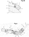
- the figure 4 shows a connector plug 6 connected to a cable 7 with an articulated extension according to the invention 1 with three components 2, 3, 5 which is fixed by screwing to the rear of the body 60 of the connector 6.
- the front part of this plug 6 may comprise means for removably holding an optoelectronic converter of the SFP / SFP + type, or an RJ45 type interface or a power or signal interface of one or more optical contacts.
- the plug 6 has a mechanically protected front portion before use by a cover 61 snapped onto the body 60. It further comprises a locking lever 62 with hooks for locking to an electronic equipment base.
- a cover 61 snapped onto the body 60.
- a locking lever 62 with hooks for locking to an electronic equipment base.
- FIG 5 illustrates an advantageous variant according to which an additional component of the extension piece may comprise three hinge parts 50, 51.1, 51.2 or 50.1, 50.2, 51 interconnected by a connecting part 53 in the general shape of Y.
- This form can be multiple in the case where the number of outputs or inputs is greater than two.
- the forward sphere portion 50 may be articulated in a ball joint with a complementary portion which may be the sphere portion 31 of a component 3 and the two rear sphere portions 51.1, 51.2 may each be connected to a complementary sphere portion which can be directly that of a component 2.
- the rear sphere portion 51 can be hinged in a ball joint with a complementary portion which may be the sphere portion 21 of a component 2 and the two rear sphere portions 50.1, 50.2 may each be connected to a complementary sphere portion which can be directly that of a component 3.
- All complementary spherical portions of the articulated extension 1 according to the invention can be assembled together so as to have a completely free ball joint in all directions.
- the male-type sphere portions 20, 50 of the various components 2, 3, 5 comprise, on their outer periphery, locking grooves 28, 58 which cooperate in accordance with several locking positions given with the locking tongues 39, 59 provided on the female-type sphere portions 31, 51.
- This partial blocking system of the ball does not modify the sealing performance provided by the seal 36, 56 because the groove / tongue fitting area is at the end of the female sphere out of the joint area.
- the figure 7 illustrates a variant according to which the component 3 forms a single piece with the body 60 of the connector 6.
- the connector-fitting portion 30 is integral with the body 60.
- This figure 7 also shows an example of a connector to which the articulated extension according to the invention 1 may be suitable: it is here a connector plug 6.1 to optoelectronic converter 63 and protection ring 64 against electromagnetic interference (EMI for " ElectroMagnetic Interference " in English).
- EMI ElectroMagnetic Interference
- the figure 8 illustrates another example of a connector, for outdoor use, to which the articulated extension 1 according to the invention may be suitable: this is a connector plug 6.2 push pull type.
- the figure 9 illustrates yet another example of a connector, for outdoor use, to which the articulated extension 1 according to the invention may be suitable: it is here a connector plug 6.3 to bayonet.
- the figure 10 illustrates yet another example of a connector to which the articulated extension according to the invention 1 may be suitable: it is here a connector plug 6.3 coaxial 6.4.
- the figure 11 illustrates alternative embodiments of extension 1 with additional components 5, including a Y-shaped as shown in FIG. figure 5 .
- the articulated extension 1.1 on the left side of the figure 11 comprises two additional components 5.1, 5.2 with the one at the front which is Y-shaped and which thus allows from a cable connection with a single cable or group of cable to separate them in two for connection by the two components 3.1, 3.2 with two separate connectors.
- the articulated extension 1.2 on the right side of the figure 11 comprises three additional components 5.1, 5.2, 5.3 with the one at the front which is Y-shaped and which thus makes it possible to join them for a connection from two separate cables or groups of cables with the two components 2.1, 2.2 in a single connector.
- the figure 12 takes up the extensions 1.1, 1.2 of the figure 11 and show their connections to the connectors 6.1 as described above. Extension pieces 5 can be added as needed independently according to the branches 2, 2.1 and / or 2.2.
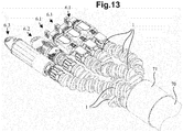
- the figure 13 finally shows a set of connectors of various types, 6.1, 6.2, 6.2 each connected to an extension 1 according to the invention, all the extensions 1 being articulated differently thanks to their different ball joints to be introduced into one and the same sheath 70 of cables or group of cables.
- the connection function on the cable is provided in this example by a sheath 71 on the cable 70.
- the sphere portion 31 of the component integrated or attached to the connector body is of the female type insofar as a portion of male sphere 50, 21 is nested therein to form a ball joint it may very well be envisaged to have a male sphere portion 31 which cooperates with a female portion.
- the sphere portion 21 of the component supporting a cable coupling part is of the male type, it is very possible to envisage having a portion of a female sphere 21.
Abstract
La présente invention concerne une rallonge (1) de connecteur (6) avec un raccord (20) sur câble à son extrémité éloignée du câble (7), la rallonge étant articulée selon au moins une liaison rotule à l'intérieur de laquelle le câble est protégé mécaniquement et contre les conditions de l'environnement extérieur.The present invention relates to an extension (1) connector (6) with a connector (20) on cable at its end remote from the cable (7), the extension being hinged in at least one ball joint connection within which the cable is mechanically protected and against the conditions of the external environment.
Description
La présente invention concerne le domaine de la connectique de transmission électrique et/ou de données.The present invention relates to the field of electrical transmission and / or data connection.
La présente invention vise à déporter un raccord sur câble de la partie arrière d'un corps de connecteur à laquelle il est usuellement fixé directement. Ce raccord sur câble peut être de type presse-étoupe, gaine thermo-rétractable ou thermocollante, manchon élastomère, surmoulage par exemple.The present invention aims to deport a cable connection of the rear part of a connector body to which it is usually directly attached. This cable connection can be of the stuffing box type, heat-shrinkable or heat-sealing sheath, elastomer sleeve, overmolding for example.
Elle concerne donc plus particulièrement une rallonge articulée de raccord sur câble pour connecteur destiné à être relié à au moins un câble supportant des contacts.It therefore relates more particularly to an articulated extension cable connector for connector intended to be connected to at least one cable supporting contacts.
L'invention s'applique de manière plus générale à tout type de connectique de transmission de signaux électriques et/ou de données et/ou de signaux radio-fréquences (RF) et/ou de signaux optiques.The invention applies more generally to any type of electrical signal transmission and / or data and / or radio frequency (RF) signals and / or optical signals.
L'invention s'applique en particulier pour une fiche de connecteur destinée à être montée sur au moins un câble supportant un ou plusieurs contacts, et à être connectée à une embase d'un panneau de boitier d'un équipement électronique.The invention applies in particular for a connector plug intended to be mounted on at least one cable supporting one or more contacts, and to be connected to a base of a box panel of electronic equipment.
Ces contacts peuvent être de type RJ45, de puissance, de données, combinés ou optiques. Ces contacts peuvent en particulier être une interface de convertisseur optoélectronique de type SFP/SFP+/QSFP/QSFP+, ou des contacts optiques.These contacts can be RJ45 type, power, data, combined or optical. These contacts may in particular be an optoelectronic converter interface type SFP / SFP + / QSFP / QSFP +, or optical contacts.
Les fiches concernées en particulier sont celles de connexion aux embases d'équipements électroniques qui mettent en oeuvre plusieurs voies optiques et/ou électriques avec des connexions, que l'on retrouve en environnement extérieur et/ou en conditions sévères notamment dans les installations de télécommunications telles que des antennes-relais de téléphonie mobile, dans les réseaux de transmission de données à haut débit vers l'habitat ou l'industrie, dans les réseaux de caméras de surveillance ou encore pour la transmission de données dans des installations ferroviaires.The cards concerned in particular are those for connection to the bases of electronic equipment which implement several optical and / or electrical paths with connections, found in an external environment and / or in severe conditions, particularly in telecommunications installations. such as mobile telephone relay antennas, high-speed data transmission networks to housing or industry, surveillance camera networks or data transmission in railway installations.
Dans le domaine de la connectique de transmission de signaux électriques et/ou de données et/ou de signaux radio-fréquences (RF) et/ou de signaux optiques, il est connu des connecteurs dont les contacts centraux sont destinés chacun à être relié à un fil ou à un contact de câble.In the field of electrical signal transmission and / or data and / or radio-frequency signal (RF) and / or optical signal connections, it is known which connectors the central contacts are each intended to be connected to. a wire or a cable contact.
Ces connecteurs peuvent être soumis à des environnements extérieurs qui peuvent être très contraignants, aussi bien en termes de température et d'humidité en qu'en termes de sollicitations mécaniques, notamment lors de l'installation ou encore d'encombrement disponible.These connectors can be subjected to external environments that can be very restrictive, both in terms of temperature and humidity and in terms of mechanical stress, especially during installation or available space.
Cela est notamment le cas entre une fiche montée sur un câble qui doit être connectée à une embase correspondante dans la plupart des équipements électroniques destinés à être implantés en environnement extérieur.This is particularly the case between a plug mounted on a cable that must be connected to a corresponding base in most electronic equipment intended to be installed in an outdoor environment.
Diverses solutions sont déjà connues pour protéger mécaniquement et/ou rendre étanches les extrémités des câbles montés sur les connecteurs.Various solutions are already known for mechanically protecting and / or sealing the ends of the cables mounted on the connectors.
On peut citer ici tout d'abord les portions de gaine souple en matériau thermoplastique simplement emmanchées autour de l'extrémité du câble et de la partie arrière du corps de connecteur auquel le câble est relié. Cette solution de gaine uniquement emmanchée n'est pas du tout satisfaisante car elle ne réalise de fait pas de protection mécanique des contacts en cas de traction sur le câble, ce qui se produit très couramment lors d'une connexion ou après au cours de la vie du connecteur.Firstly, there may be mentioned thermoplastic flexible sheath portions simply fitted around the end of the cable and the rear part of the connector body to which the cable is connected. This solution sleeve only fitted is not at all satisfactory because it does not actually do mechanical protection of the contacts in case of traction on the cable, which occurs very commonly during a connection or after during the connector life.
Une telle gaine peut être surmoulée autour du câble et du corps de connecteur. Avec une gaine surmoulée, le niveau de rétention mécanique du câble reste insuffisant de sorte qu'en cas de sollicitation mécanique par traction, les contacts peuvent être aisément endommagés.Such a sheath may be overmolded around the cable and the connector body. With a molded sheath, the level of mechanical retention of the cable remains insufficient so that in case of mechanical stress by traction, the contacts can be easily damaged.
On connaît également des connecteurs de type HDMI qui sont en deux parties articulées l'une à l'autre par liaison pivot entre elles, ce qui permet d'accompagner en partie le câble ou le circuit flexible interne lorsque ce dernier est plié. Ce type de connecteur articulé ne permet ni d'avoir une bonne étanchéité, ni de faire une rétention efficace en traction du câble.There are also known connectors of the HDMI type which are in two parts hinged to each other by pivot connection between them, which allows to partially accompany the cable or the internal flexible circuit when the latter is bent. This type of articulated connector does not allow to have a good seal, or to make an effective retention in tension of the cable.
En outre, toutes ces solutions selon l'état de l'art présentent des inconvénients majeurs.In addition, all these solutions according to the state of the art have major disadvantages.
Tout d'abord, aucune de ces solutions ne permet de faire un montage avec protection mécanique et étanchéité, in situ, c'est-à-dire sur le lieu de l'installation ou équipement électronique pour lequel le connecteur est destiné.First of all, none of these solutions makes it possible to mount with mechanical protection and sealing, in situ, that is to say at the place of installation or electronic equipment for which the connector is intended.
En outre, aucune d'entre elles ne permet d'avoir un bon contrôle du rayon de courbure qui peut être infligé au câble lors du montage in situ.In addition, none of them allows to have a good control of the radius of curvature that can be inflicted to the cable during in situ assembly.
Or, dans certaines configurations, notamment de place disponible limitée, un opérateur peut involontairement conférer une courbure au câble qui peut nuire à la transmission des signaux, en particulier optiques, ou être néfaste à l'intégrité des contacts.However, in certain configurations, including limited availability of space, an operator may inadvertently give a curvature to the cable that may interfere with the transmission of signals, in particular optical, or be detrimental to the integrity of the contacts.
Enfin, quelle que soit la solution actuelle, le câble n'est pas de fait protégé mécaniquement contre un écrasement qui peut se produire in situ.Finally, whatever the current solution, the cable is not in fact mechanically protected against crushing that can occur in situ.
Il existe par conséquent un besoin pour améliorer les solutions de montage de connecteurs à des câbles de transmission de signaux électriques et/ou de données et/ou de signaux RF, notamment afin de protéger mécaniquement l'extrémité des câbles et leurs contacts éventuels ainsi que ceux des connecteurs, quelle que soit les types de sollicitations mécaniques auxquelles ils peuvent être confrontés, et ce tout en garantissant une étanchéité vis-à-vis de l'environnement extérieur.There is therefore a need to improve connector mounting solutions for electric signal transmission cables and / or data and / or RF signals, in particular to mechanically protect the ends of cables and their possible contacts as well as those of the connectors, whatever the types of mechanical stresses to which they may be confronted, while ensuring a seal with respect to the external environment.
Le but de l'invention est de répondre au moins en partie à ce besoin.The object of the invention is to respond at least in part to this need.
Pour ce faire, l'invention concerne un dispositif formant une rallonge de raccord sur câble pour connecteur destiné à être relié à au moins un câble électrique et/ou optique, le dispositif comprenant :
- un premier composant comprenant une partie de raccord sur câble formant fourreau adapté pour être traversé avec étanchéité par un câble tout en assurant la protection du câble vis-à-vis de l'extérieur, et une partie d'articulation constituée par une portion de sphère formée intégralement ou fixée au fourreau du raccord sur câble,
- un deuxième composant comprenant une partie de raccord sur connecteur adaptée pour être formée intégralement ou fixée avec un corps de connecteur et une partie d'articulation constituée par une portion de sphère formée intégralement ou fixée à la partie de raccord sur connecteur,
- a first component comprising a cable coupling part forming a sheath adapted to be penetrated with sealing by a cable while ensuring the protection of the cable vis-à-vis the outside, and a hinge portion constituted by a portion of sphere formed integrally or fixed to the sleeve of the cable connection,
- a second component comprising a connector fitting portion adapted to be integrally formed or secured to a connector body and a hinge portion formed by a sphere portion integrally formed or attached to the connector fitting portion,
Dans la rallonge selon l'invention:
- les portions de sphère du premier et deuxième composant délimitent chacune intérieurement un passage traversant pour le câble ;
- les portions de sphère du premier et du deuxième composant sont chacune assemblées par emmanchement avec une portion de sphère complémentaire d'un composant de la rallonge, de sorte à réaliser au moins une liaison rotule entre la partie de raccord sur câble du premier composant et la partie de raccord sur connecteur du deuxième composant.
- the sphere portions of the first and second components each delimit a through passage for the cable;
- the sphere portions of the first and second components are each assembled by fitting with a complementary sphere portion of a component of the extension, so as to provide at least one ball joint connection between the cable connection portion of the first component and the connector part of the second component.
Selon un mode de réalisation avantageux, la partie de raccord sur câble est configurée en un presse-étoupe de la rallonge.According to an advantageous embodiment, the cable connection portion is configured as a gland of the extension.
Ainsi, l'invention consiste essentiellement à définir une rallonge de connecteur avec un raccord sur câble à son extrémité éloignée du câble, la rallonge étant articulée selon au moins une liaison rotule à l'intérieur de laquelle le câble est protégé mécaniquement et contre les conditions de l'environnement extérieur.Thus, the invention essentially consists in defining a connector extension with a cable connection at its end remote from the cable, the extension being hinged in at least one ball joint connection inside which the cable is mechanically protected and against the conditions of the external environment.
Ainsi, la longueur de la rallonge est parfaitement modulable selon les besoins en fonction du nombre d'éléments qui la compose.Thus, the length of the extension is perfectly flexible according to the needs according to the number of elements that compose it.
Le raccord sur câble est configuré pour d'une part assurer une parfaite étanchéité vis-à-vis de l'extérieur.The cable connection is configured to ensure a perfect seal against the outside.
Le diamètre des passages traversant à l'intérieur des différents composants de la rallonge et donc du raccord sur câble peut être suffisamment important pour laisser passer la majorité des types d'interfaces de signal existantes, par exemple de type optique, puissance, données, combiné, RJ45, LC Duplex, LC simplex, MPO, USB...,The diameter of the passages passing through the various components of the extension and thus of the cable connection can be large enough to allow the majority of the types of existing signal interfaces to pass, for example of the optical, power, data, combined type. , RJ45, LC Duplex, LC simplex, MPO, USB ...,
Les diamètres de câble qui peuvent traverser la rallonge peuvent être très variables, par exemple dans une gamme de 4 à 11,5 mm.The cable diameters that can cross the extension can be very variable, for example in a range of 4 to 11.5 mm.
La partie raccord sur câble est avantageusement configurée en un presse-étoupe de la rallonge pour pouvoir :
- garantir une étanchéité en respectant la norme IP65, IP 67, IP68, ou UL50E.
- être aisément finalisé in-situ,
- garantir une force de rétention du câble élevée, typiquement de 150N à 250N, avec un couple de serrage de 2,5 N.m que l'on peut atteindre manuellement.
- guarantee a seal in accordance with IP65, IP 67, IP68, or UL50E.
- be easily finalized in-situ,
- guarantee a high cable retention force, typically from 150N to 250N, with a torque of 2.5 Nm that can be reached manually.
Grâce à l'invention, on maîtrise le diamètre d'enroulement/courbure du câble relié au connecteur, ce qui garantit une protection mécanique du câble, notamment lors d'une traction, et des contacts centraux du connecteur et le cas échéant de ceux du câble.Thanks to the invention, the diameter of winding / curvature of the cable connected to the connector is controlled, which guarantees a mechanical protection of the cable, in particular during a pull, and the central contacts of the connector and, if appropriate, those of the connector. cable.
De plus, les câbles et contacts sont protégés contre l'écrasement, car tous les composants de la rallonge peuvent être suffisamment rigides pour résister à ce type d'efforts.In addition, the cables and contacts are protected against crushing, because all the components of the extension can be rigid enough to withstand such efforts.
Ainsi, on garantit la transmission des signaux électriques et/ou optiques par le câble.Thus, the transmission of electrical and / or optical signals by the cable is guaranteed.
En outre, la rallonge selon l'invention permet de pouvoir orienter à souhait selon toutes orientations le câble à la sortie d'un équipement électronique. La variante où l'on peut bloquer partiellement les sphères les unes par rapport aux autres permet de figer les rotules en rotation et donc le parcours suivi par le câble.In addition, the extender according to the invention can be directed as desired in all directions the cable at the output of an electronic equipment. The variant where you can partially block the spheres relative to each other makes it possible to freeze the rotational joints and thus the path followed by the cable.
La rallonge selon l'invention est complètement modulaire et on peut rajouter autant de troisièmes composants, c'est-à-dire de protections du câble avec liaisons rotules, que l'on souhaite. Chaque rajout d'un composant supplémentaire consiste en un emmanchement à force d'une portion de sphère dans une autre d'un composant.The extension according to the invention is completely modular and can be added as many third components, that is to say protections of the cable with ball joints, as desired. Each addition of an additional component consists of a force fitting of a sphere portion in another of a component.
La longueur du câble traversée par la rallonge peut donc être adaptée à souhait selon les différentes configurations d'installations ou d'équipements électroniques auxquels les connecteurs sont reliés. Cela est avantageux notamment lorsqu'il s'agit des installations ou des équipements existants.The length of the cable traversed by the extension cord can therefore be adapted according to the various configurations of installations or electronic equipment to which the connectors are connected. This is advantageous especially when it comes to existing facilities or equipment.
Selon une variante de réalisation avantageuse, la partie de raccord sur câble du premier composant comprend sur sa périphérie extérieure un filetage pour visser la bague de fermeture du raccord su câble.According to an advantageous embodiment variant, the cable connection part of the first component comprises on its outer periphery a thread for screwing the closure ring of the cable connector.
Selon une autre variante de réalisation avantageuse, la partie de raccord sur connecteur du deuxième composant comprend sur sa périphérie intérieure un filetage pour visser le deuxième composant directement sur le corps de connecteur.According to another advantageous embodiment, the connector portion of the second component portion comprises on its inner periphery a thread for screwing the second component directly on the connector body.
Selon un mode de réalisation, les portions de sphère du premier et du deuxième composant peuvent être assemblées par emmanchement directement l'une avec l'autre.According to one embodiment, the sphere portions of the first and second components can be assembled by fitting directly with each other.
Alternativement, la rallonge peut, comprendre au moins un troisième composant comprenant au moins deux parties d'articulation constituée chacune par une portion de sphère formée intégralement ou fixée l'une à l'autre, la portion de sphère du premier composant étant assemblée par emmanchement directement avec une portion de sphère d'au moins un troisième composant pour former une liaison rotule, la portion de sphère du deuxième composant étant assemblée par emmanchement directement avec une portion de sphère d'au moins un troisième composant pour former une autre liaison rotule.Alternatively, the extension may comprise at least a third component comprising at least two hinge parts each consisting of a sphere portion integrally formed or fixed to each other, the sphere portion of the first component being assembled by fitting directly with a sphere portion of at least a third component to form a ball joint, the sphere portion of the second component being joined by fitting directly with a sphere portion of at least a third component to form another ball joint.
Le troisième composant peut comprendre au moins trois parties d'articulation reliées entre elles par une partie de liaison.The third component may comprise at least three hinge parts interconnected by a connecting part.
La partie de liaison peut être en forme générale de Y.The connecting portion may be in the general form of Y.
Selon un mode de réalisation, la rallonge comprend au moins deux troisièmes composants une portion de sphère de l'un des troisième composant étant assemblée par emmanchement directement avec une portion de sphère d'un autre des troisièmes composants pour former une autre liaison rotule.According to one embodiment, the extension comprises at least two third components, a sphere portion of one of the third components being assembled by fitting directly with a sphere portion of another of the third components to form another ball joint.
Avantageusement, au moins une portion de sphère est constituée d'au moins deux calottes sphériques assemblées entre elles avec un joint d'étanchéité agencé à l'intérieur de leur assemblage.Advantageously, at least one sphere portion consists of at least two spherical caps assembled together with a seal arranged inside their assembly.
Selon une première variante, chacune des deux calottes sphériques peut comprendre des reliefs et/ou creux d'encliquetage, de sorte à réaliser l'assemblage mutuel des calottes par encliquetage.According to a first variant, each of the two spherical caps may comprise reliefs and / or snap-in recesses, so as to perform the mutual assembly of the caps by snapping.
Selon une deuxième variante, chacune des deux calottes sphériques comprend des filetages, de sorte à réaliser l'assemblage mutuel des calottes par vissage.According to a second variant, each of the two spherical caps comprises threads, so as to achieve the mutual assembly of the caps by screwing.
Avantageusement, l'une des deux calottes sphériques sous la forme d'une bague comprend un cran de verrouillage adapté pour coopérer par crantage avec au moins un relief complémentaire réalisé dans l'autre des deux calottes sphériques, de sorte à verrouiller le vissage, et ce quelle que soit la rotation de la liaison rotule assemblée.Advantageously, one of the two spherical caps in the form of a ring comprises a locking notch adapted to cooperate by notching with at least one complementary relief made in the other of the two spherical caps, so as to lock the screwing, and whatever the rotation of the assembled ball joint connection.
De préférence, la bague est fendue.Preferably, the ring is split.
Selon une première alternative, deux portions de sphères assemblées directement l'une à l'autre par emmanchement étant en outre adaptées pour avoir une rotation libre de l'une par rapport à l'autre.According to a first alternative, two portions of spheres assembled directly to one another by fitting are further adapted to have a free rotation of one relative to the other.
Selon une deuxième alternative, deux portions de sphères assemblées directement l'une à l'autre par emmanchement comprenant en outre des reliefs et/ou creux de blocage en rotation, de sorte à avoir une rotation bloquée selon un angle donné de l'une par rapport à l'autre.According to a second alternative, two portions of spheres assembled directly to one another by fitting further comprising reliefs and / or hollow rotational locking, so as to have a rotation locked at a given angle of one by report to the other.
Tous les composants de la rallonge sont de préférence en matériau électriquement isolant, de préférence encore dans le même matériau que celui du corps de connecteur.All of the components of the extender are preferably of electrically insulating material, more preferably of the same material as that of the connector body.
L'invention a également pour objet un connecteur, destiné à être relié à au moins un câble, comprenant un corps formé intégralement ou fixé à la partie de raccord sur connecteur du deuxième composant d'une rallonge telle que décrite précédemment.The invention also relates to a connector, intended to be connected to at least one cable, comprising a body formed integrally or fixed to the connector portion of the second component part of an extension as described above.
Le connecteur peut être destiné à être relié à deux câbles ou deux groupes distincts, en combinaison avec une rallonge à partie de liaison en Y, une partie d'articulation d'un troisième composant étant assemblée directement avec la partie de raccord du deuxième composant en étant traversée par les deux câbles ou groupes de câbles distincts, tandis que chacune des deux autres parties d'articulation formant les branches du Y du troisième composant est traversée par l'un des deux câbles ou groupes de câbles distincts.The connector may be adapted to be connected to two separate cables or two groups, in combination with an extension with a Y-connection portion, a hinge portion of a third component being assembled directly with the connecting portion of the second component. being crossed by the two cables or groups of separate cables, while each of the other two hinge portions forming the branches of the Y of the third component is traversed by one of two separate cables or groups of cables.
L'invention a également pour objet un ensemble de connecteurs, comprenant une pluralité de connecteurs comme ci-avant, comprenant une gaine enveloppant tout ou partie des composants de toutes les rallonges.The invention also relates to a set of connectors, comprising a plurality of connectors as above, comprising a sheath wrapping all or part of the components of all the extensions.
L'ensemble peut comprendre au moins deux connecteurs en combinaison avec une rallonge à partie de liaison en Y, une partie d'articulation d'un troisième composant étant traversée par un seul câble ou un seul groupe de câbles, tandis que chacune des deux autres parties d'articulation formant les branches du Y du troisième composant est assemblée directement avec la partie de raccord du deuxième composant d'un des connecteurs, en étant traversée par une partie du seul câble ou du seul groupe de câbles.The assembly may comprise at least two connectors in combination with an extension with a Y-connection portion, a hinge portion of a third component being traversed by a single cable or a single group of cables, while each of the other two Y-branch joint portions of the third component are assembled directly with the connecting portion of the second component of one of the connectors, through which a portion of the single cable or group of cables passes.
Cette variante selon l'invention avec un composant en Y permet de protéger et séparer des câbles hybrides, c'est-à-dire avec des fils de transmission de signaux mixtes, par exemple des fils de transmission de signaux en RJ45 séparés de fils de puissance, des fibres optiques séparés de fils de puissance, des fils de transmission de données séparés des fils de puissance. Cette variante ne se limite pas à deux connecteurs à relier à un câble, ou deux câbles à relier à un connecteur, mais à de multiples connecteurs ou câbles.This variant according to the invention with a Y component makes it possible to protect and separate hybrid cables, that is to say with mixed signal transmission wires, for example RJ45 signal transmission wires separated from power, optical fibers separated from power wires, data transmission wires separated from the power wires. This variant is not limited to two connectors to be connected to a cable, or two cables to be connected to a connector, but to multiple connectors or cables.
L'invention concerne également sous un autre de ses aspects, un procédé de montage in-situ d'un connecteur avec une rallonge décrite précédemment, sur au moins un câble, comprenant les étapes suivantes :
- a/ enfilement du ou des câbles à l'intérieur des composants de la rallonge;
- b/ connexion des contacts centraux du câble avec ceux du connecteur;
- c/ le cas échéant, fixation de la partie raccord du deuxième composant avec le corps du connecteur ;
- d/ réalisation du raccord sur câble avec la partie raccord sur câble du premier composant de la rallonge.
- a / threading the cable or cables inside the components of the extension;
- b / connection of the central contacts of the cable with those of the connector;
- c) if necessary, fixing the connecting part of the second component with the body of the connector;
- d / realization of the cable connection with the cable connection part of the first component of the extension.
L'étape a/ est réalisée avec les composants de la rallongé déjà assemblés par emmanchement entre eux, ou non.Step a / is performed with the components of the lengthened already assembled by fitting together, or not.
D'autres avantages et caractéristiques de l'invention ressortiront mieux à la lecture de la description détaillée d'exemples de mise en oeuvre de l'invention faite à titre illustratif et non limitatif en référence aux figures suivantes parmi lesquelles :
- la
figure 1 est une vue en perspective en éclaté d'un exemple de rallonge de connecteur avec un presse-étoupe selon l'invention; - la
figure 2 est une en perspective en éclaté d'une variante avantageuse de la rallonge de connecteur avec un presse-étoupe selon l'invention ; - la
figure 3 est une vue en perspective de la rallonge selon lafigure 2 une fois assemblée et avec le presse-étoupe fixé sur la rallonge; - la
figure 3A est une vue en coupe longitudinale de lafigure 3 ; - la
figure 3B est une vue en coupe de détail agrandi de lafigure 3A ; - les
figures 3C et 3D sont des vues respectivement en éclaté et en coupe longitudinale d'une variante d'assemblage d'une rallonge de connecteur selon l'invention ; - la
figure 4 est une vue en perspective d'un connecteur reliée à un câble et sur lequel est fixé une rallonge avec son presse-étoupe selon lesfigures 3 à 3B ; - la
figure 5 est une vue en perspective d'une variante avantageuse en forme de Y d'un composant de la rallonge selon l'invention ; - la
figure 6 est une vue en perspective d'une variante de la rallonge selon lesfigures 3 à 3B ; - la
figure 7 est une vue en perspective d'une fiche de connecteur à convertisseur optoélectronique destiné à être reliée à un câble et dont le corps est intégral avec la partie de raccord sur connecteur d'une rallonge avec son presse-étoupe selon l'invention ; - les
figures 8 à 10 sont des vues en perspective d'autres types de connecteur destinés à être relié chacun à un câble et dont le corps est fixé par vissage à la partie de raccord sur connecteur d'une rallonge avec son presse-étoupe selon l'invention ; - la
figure 11 illustre en vue en perspective d'exemples de rallonge selon l'invention avec la variante de composant en Y comme selon lafigure 5 ; - la
figure 12 est une vue en perspective de connecteur ou d'ensemble de connecteurs avec les rallonges selon lafigure 11 ; - la
figure 13 est une vue en perspective d'un ensemble de connecteurs de types variés, chacun avec une rallonge selon l'invention, rallonges reliées au câble par une gaine.
- the
figure 1 is an exploded perspective view of an exemplary connector extension with a gland according to the invention; - the
figure 2 is an exploded perspective view of an advantageous variant of the connector extension with a gland according to the invention; - the
figure 3 is a perspective view of the extension according to thefigure 2 once assembled and with the stuffing box attached to the extension; - the
figure 3A is a longitudinal sectional view of thefigure 3 ; - the
figure 3B is an enlarged detail sectional view of thefigure 3A ; - the
Figures 3C and 3D are respectively exploded and longitudinal sectional views of an assembly variant of a connector extension according to the invention; - the
figure 4 is a perspective view of a connector connected to a cable and on which is fixed an extension with its gland according to theFigures 3 to 3B ; - the
figure 5 is a perspective view of an advantageous Y-shaped variant of a component of the extension according to the invention; - the
figure 6 is a perspective view of a variant of the extension according toFigures 3 to 3B ; - the
figure 7 is a perspective view of an optoelectronic converter connector plug intended to be connected to a cable and whose body is integral with the connector portion of an extension connector with its gland according to the invention; - the
Figures 8 to 10 are perspective views of other types of connector intended to be each connected to a cable and whose body is screwed to the connector portion of a connector extension with its gland according to the invention; - the
figure 11 illustrates in perspective view examples of extension according to the invention with the component variant in Y as in thefigure 5 ; - the
figure 12 is a perspective view of a connector or connector assembly with the extensions according to thefigure 11 ; - the
figure 13 is a perspective view of a set of connectors of various types, each with an extension according to the invention, extensions connected to the cable by a sheath.
La rallonge 1 selon l'invention est une rallonge articulée de raccord sur câble 4 pour un connecteur 6 relié à au moins un câble 7.The
Telle qu'illustrée en
Le premier composant 2 comprend une partie de raccord sur câble 20 sous la forme d'un fourreau adapté pour être traversé avec étanchéité par le câble 7 tout en assurant la protection du câble vis-à-vis de l'extérieur, et une partie d'articulation 21 constituée par une portion de sphère formée intégralement ou fixée au fourreau 20 du raccord sur câble.The
La portion de sphère 21 est percée d'un passage traversant 22 pour le câble dans la continuité de celui du fourreau 20.The
Le deuxième composant 3 comprend une partie de raccord sur connecteur 30 adaptée pour être formée intégralement ou fixée avec le corps 60 de connecteur et une partie d'articulation 31 constituée par une portion de sphère formée intégralement ou fixée à la partie de raccord sur connecteur,The
La portion de sphère 31 est percée d'un passage traversant 32 pour le câble.The
Pour réaliser la liaison rotule de la rallonge articulée 1, les portions de sphère 21, 31 sont assemblées entre elles, par emmanchement à force.To achieve the ball joint connection of the articulated
Dans le mode de réalisation des
Plus précisément, le composant supplémentaire 5 comprend deux parties d'articulation 50, 51 constituée chacune par une portion de sphère formée intégralement dans la même pièce.More specifically, the
Un premier assemblage par emmanchement est ainsi réalisé entre la portion de sphère 21 du composant 2 et la portion de sphère 51 du composant supplémentaire 5 pour former une première liaison rotule.A first fitting assembly is thus formed between the
Un deuxième assemblage par emmanchement est réalisé entre la portion de sphère 31 du composant 3 et la portion de sphère 50 du composant supplémentaire 5 pour former une deuxième liaison rotule.A second fitting assembly is made between the
Plusieurs éléments 5 peuvent être emboités à la suite selon la longueur souhaitée de rallonge.
Ainsi, la rallonge 1 des
Lorsque la rallonge articulée 1 est fixée sur le corps 60 du connecteur, on peut munir la partie de raccord sur connecteur 30 du composant 3, prévue à cet effet d'un filetage 33. Comme montré en
Pour réaliser le presse-étoupe 4 qui coopère avec la rallonge 1 selon l'invention, on peut munir la partie raccord sur câble 20 du composant 2 d'un filetage extérieur 23 sur lequel vient se visser un écrou 40 au filetage intérieur 41 complémentaire, comme montré en
Au préalable, un premier joint fendu 42 ainsi qu'une bague fendue 43 sont positionnés autour du câble 7. Comme montré sur la
Pour chaque liaison rotule, il est préférable de prévoir une étanchéité à l'interface entre portions de sphère mâle et femelle.For each ball joint, it is preferable to provide a seal at the interface between portions of the male and female sphere.
La
Comme montré sur cette
Pour l'assemblage proprement dit de la liaison rotule avec insertion du joint 36, on peut procéder de deux manières différentes.For the actual assembly of the ball joint connection with insertion of the
La première manière consiste à insérer et maintenir le joint 36 entre les deux calottes 34, 35 puis à assembler celles-ci l'une à l'autre, notamment par encliquetage, puis enfin à emmancher à force la portion de sphère mâle 50 dans la portion de sphère femelle 31.The first way is to insert and maintain the
Alternativement, on peut procéder à l'emmanchement de la portion de sphère mâle 50 dans la calotte 34, puis à l'insertion du joint autour de la portion de sphère mâle 50 et enfin à la fixation des calottes 34, 35 entre elles en maintenant le joint inséré entre elles, en formant ainsi la portion de sphère femelle 31 en liaison rotule autour de la portion de sphère mâle 50.Alternatively, one can proceed to the fitting of the
Alternativement, les deux pièces 34 et 35 peuvent être une seule pièce monobloc et le joint 36 peut être encastré dans la rainure ménagée par déformation ou surmoulé dans la pièce monobloc. De même, la portion de sphère male 50 est ensuite encastrée par déformation dans la portion femelle 31.Alternatively, the two
Comme montré en
Pour ce faire, la calotte 34 présente un filetage intérieur 340 adapté pour coopérer par vissage avec le filetage extérieur 350 de la bague 35.To do this, the
Avantageusement, il est prévu de réaliser un verrouillage entre la bague 35 et la calotte 34 une fois le vissage réalisé. Ainsi, la bague 35 présente, sur sa périphérie extérieure, un cran de verrouillage 351 adapté pour coopérer par crantage avec un des reliefs complémentaires 341 réalisés en bout de la calotte 34.Advantageously, it is intended to provide a lock between the
Selon cette variante, la bague 35 est de préférence fendue, ce qui permet de positionner initialement la bague 35 dans l'espace à diamètre réduit autour de la portion de sphère mâle 50, par exemple entre cette dernière et la portion de sphère adjacente 51.According to this variant, the
L'assemblage est réalisé de la manière suivante.The assembly is carried out as follows.
La portion de sphère mâle 50 est emmanchée dans la calotte 34.The portion of the
Puis, la bague 35 est vissée sur et autour de la calotte 34 par le biais des filetages complémentaires 340, 350.Then, the
Lorsque le cran de verrouillage 351 se trouve en prise crantée dans l'un des reliefs complémentaires 341, l'ensemble formé la calotte 34 et la bague 35 est définitivement solidaire et le verrouillage réalisé garantit que la bague 35 ne puisse se dévisser, et ce quelle que soit la rotation de la portion de sphère 50.When the locking
Le même type d'assemblage peut être réalisé entre la bague 55 et la calotte 54 (
La
Telle qu'illustrée, la fiche 6 a une partie avant protégée mécaniquement avant utilisation par un capot 61 encliqueté sur le corps 60. Elle comporte en outre un levier de verrouillage 62 à crochets pour la verrouiller à une embase d'équipement électronique. Pour plus de détail, on pourra se reporter avantageusement à la demande de brevet européenne
La
Ainsi, comme montré à gauche sur cette
A l'inverse, comme montré à droite sur cette
Toutes les portions de sphère complémentaires de la rallonge articulée 1 selon l'invention, peuvent être assemblées entre elles de manière à pouvoir avoir une rotule complètement libre selon toutes les directions.All complementary spherical portions of the articulated
On peut aussi avantageusement prévoir la possibilité de bloquer en rotation entre elles les portions complémentaires de sphère, selon une ou plusieurs positions de rotulage.One can also advantageously provide the possibility of locking in rotation between them the complementary portions of the sphere, in one or more positions of swiveling.
La
Autrement dit, lorsqu'une portion de sphère femelle 31, 51 est orientée dans une position de rotulage donnée par rapport à la portion de sphère mâle 20, 50 autour de laquelle elle est emmanchée, les languettes 39, 59 viennent s'insérer dans les gorges 28, 58 et ainsi bloquer une des directions de rotation de la liaison rotule entre elles.In other words, when a
Ce système de blocage partiel de la rotule ne modifie pas les performances d'étanchéité assuré par le joint 36, 56 car la zone d'emmanchement gorges / languettes se trouve en extrémité de la sphère femelle hors de la zone du joint.This partial blocking system of the ball does not modify the sealing performance provided by the
La
Cette
La
La
La
La
Plus précisément, la rallonge articulée 1.1 sur la partie de gauche de la
La rallonge articulée 1.2 sur la partie de droite de la
La
La
D'autres variantes et avantages de l'invention peuvent être réalisés sans pour autant sortir du cadre de l'invention.Other variants and advantages of the invention can be realized without departing from the scope of the invention.
Par exemple, si dans l'ensemble des exemples illustrés, la portion de sphère 31 du composant intégré ou fixé au corps de connecteur est de type femelle dans la mesure où une portion de sphère mâle 50, 21 y est emboîtée pour former une liaison rotule, on peut très bien envisager d'avoir une portion de sphère 31 mâle qui coopère avec une portion femelle.For example, if in all of the illustrated examples, the
A l'inverse, si dans l'ensemble des exemples illustrés, la portion de sphère 21 du composant supportant une partie de raccord sur câble est de type mâle, on peut très bien envisager d'avoir une portion de sphère 21 femelle.Conversely, if in all of the illustrated examples, the
De manière générale, toutes les combinaisons mâle/femelle peuvent être envisagées pour les différents composants de la rallonge selon l'invention.In general, all male / female combinations can be envisaged for the various components of the extension according to the invention.
L'invention n'est pas limitée aux exemples qui viennent d'être décrits ; on peut notamment combiner entre elles des caractéristiques des exemples illustrés au sein de variantes non illustrées.The invention is not limited to the examples which have just been described; it is possible in particular to combine with one another characteristics of the illustrated examples within non-illustrated variants.
Claims (15)
chacune des deux calottes sphériques (34, 35 ; 54, 55) comprenant de préférence, des reliefs et/ou creux d'encliquetage (38 ; 37), de sorte à réaliser l'assemblage mutuel des calottes par encliquetage, chacune des deux calottes sphériques (34, 35; 54, 55) comprenant de préférence des filetages (340, 350 ; 540, 550), de sorte à réaliser l'assemblage mutuel des calottes par vissage, de préférence l'une (35 ; 55) des deux calottes sphériques sous la forme d'une bague, de préférence fendue, comprenant un cran de verrouillage (351), adapté pour coopérer par crantage avec au moins un relief complémentaire (341) réalisé dans l'autre (34 ; 54) des deux calottes sphériques, de sorte à verrouiller le vissage, et ce quelle que soit la rotation de la liaison rotule assembléeExtension piece (1) according to one of the preceding claims, wherein at least one sphere portion (31; 51) consists of at least two spherical caps (34, 35; 54, 55) assembled together with a seal (36; 56) arranged within their assembly,
each of the two spherical caps (34, 35; 54, 55) preferably comprising reliefs and / or snap-in recesses (38; 37), so as to perform the mutual assembly of the caps by snapping, each of the two caps spherical members (34, 35; 54, 55) preferably comprising threads (340, 350, 540, 550), so as to effect the mutual assembly of the caps by screwing, preferably one (35; 55) of the two. spherical caps in the form of a ring, preferably split, comprising a locking notch (351), adapted to cooperate by detent with at least one complementary relief (341) made in the other (34; 54) of the two caps spherical, so to lock the screwing, regardless of the rotation of the ball joint assembly
une partie d'articulation (51) d'un troisième composant étant traversée par un seul câble ou un seul groupe de câbles, tandis que chacune des deux autres parties d'articulation (50.1, 50.2) formant les branches du Y du troisième composant est assemblée directement avec la partie de raccord du deuxième composant d'un des connecteurs, en étant traversée par une partie du seul câble ou du seul groupe de câbles.A connector assembly, comprising a plurality of connectors according to claim 18 or 19, comprising a sheath wrapping all or part of the components of all the extensions, preferably with
a hinge portion (51) of a third component being traversed by a single cable or a single group of cables, while each of the other two hinge portions (50.1, 50.2) forming the branches of the Y of the third component is assembled directly with the connecting part of the second component of one of the connectors, through which a part of the single cable or the only group of cables passes.
Applications Claiming Priority (1)
| Application Number | Priority Date | Filing Date | Title |
|---|---|---|---|
| FR1762297A FR3075493B1 (en) | 2017-12-15 | 2017-12-15 | ARTICULATED CABLE CONNECTOR EXTENSION FOR A CONNECTOR TO BE CONNECTED TO AT LEAST ONE CABLE |
Publications (1)
| Publication Number | Publication Date |
|---|---|
| EP3499665A1 true EP3499665A1 (en) | 2019-06-19 |
Family
ID=61802102
Family Applications (1)
| Application Number | Title | Priority Date | Filing Date |
|---|---|---|---|
| EP18211082.5A Withdrawn EP3499665A1 (en) | 2017-12-15 | 2018-12-07 | Articulated extension lead for connection to a cable for connector to be connected to at least one cable |
Country Status (4)
| Country | Link |
|---|---|
| US (1) | US20190190190A1 (en) |
| EP (1) | EP3499665A1 (en) |
| CN (1) | CN110021845A (en) |
| FR (1) | FR3075493B1 (en) |
Cited By (1)
| Publication number | Priority date | Publication date | Assignee | Title |
|---|---|---|---|---|
| FR3126557A1 (en) * | 2021-09-01 | 2023-03-03 | Naval Group | CONCENTRATION SYSTEM OF ELECTRICAL SIGNALS BY SEVERAL CONNECTORS AND CABLE GLAND SYSTEM |
Families Citing this family (12)
| Publication number | Priority date | Publication date | Assignee | Title |
|---|---|---|---|---|
| US11707819B2 (en) | 2018-10-15 | 2023-07-25 | General Electric Company | Selectively flexible extension tool |
| US11702955B2 (en) | 2019-01-14 | 2023-07-18 | General Electric Company | Component repair system and method |
| US11692650B2 (en) | 2020-01-23 | 2023-07-04 | General Electric Company | Selectively flexible extension tool |
| US11752622B2 (en) | 2020-01-23 | 2023-09-12 | General Electric Company | Extension tool having a plurality of links |
| US11613003B2 (en) | 2020-01-24 | 2023-03-28 | General Electric Company | Line assembly for an extension tool having a plurality of links |
| US11371437B2 (en) | 2020-03-10 | 2022-06-28 | Oliver Crispin Robotics Limited | Insertion tool |
| CN111555075B (en) * | 2020-05-15 | 2021-08-27 | 沈阳飞机工业(集团)有限公司 | Data line that can flexibly buckle |
| US11654547B2 (en) | 2021-03-31 | 2023-05-23 | General Electric Company | Extension tool |
| US20220349498A1 (en) * | 2021-04-29 | 2022-11-03 | APG Vision LLC | Ball Mount with Integrated Cable Gland |
| US11435536B1 (en) * | 2021-07-29 | 2022-09-06 | Teledyne Instruments, Inc. | Latched optical feedthrough system for subsea wellhead penetration using spherical seals |
| FR3126558A1 (en) * | 2021-09-01 | 2023-03-03 | Naval Group | CONCENTRATION SYSTEM OF ELECTRICAL SIGNALS BY CONNECTOR AND SEVERAL CABLE GLAND SYSTEMS |
| CN117559343A (en) * | 2024-01-11 | 2024-02-13 | 国网湖北省电力有限公司 | Wear-resistant reinforcing sleeve for line butt joint and use method thereof |
Citations (6)
| Publication number | Priority date | Publication date | Assignee | Title |
|---|---|---|---|---|
| FR2505566A1 (en) * | 1981-05-08 | 1982-11-12 | Carreras Jacques | Articulated metal sheath for electric cables - uses succession of cylindrical and spherical metal segments fitting one into other to form sheath |
| US5069486A (en) * | 1985-04-09 | 1991-12-03 | Tsubakimoto Chain Co. | Flexible supporting sheath for cables and the like |
| EP0965784A1 (en) * | 1998-06-15 | 1999-12-22 | Internova International Innovation Company B.V. | Protective cover for cables or conduits |
| US20040119246A1 (en) * | 2002-08-02 | 2004-06-24 | Josef Woller | Sealing device |
| JP5910832B2 (en) * | 2013-09-12 | 2016-04-27 | ヒロセ電機株式会社 | Cable holding device |
| WO2017140901A1 (en) * | 2016-02-19 | 2017-08-24 | NDT Global Corporate Ltd. Ireland | Connecting element |
Family Cites Families (13)
| Publication number | Priority date | Publication date | Assignee | Title |
|---|---|---|---|---|
| US886262A (en) * | 1906-09-01 | 1908-04-28 | George F Childress | Switch-cord plug. |
| US1284099A (en) * | 1915-08-12 | 1918-11-05 | Lewis F Harris | Pipe-coupling. |
| GB8925819D0 (en) * | 1989-11-15 | 1990-01-04 | Stc Plc | Flexible cable termination |
| US5286071A (en) * | 1992-12-01 | 1994-02-15 | General Electric Company | Bellows sealed ball joint |
| US5740839A (en) * | 1997-03-25 | 1998-04-21 | Kuo; Hsien-Jen | Flexible extension conduit |
| US6029293A (en) * | 1998-02-06 | 2000-02-29 | Speakman Company | Sensor assembly having flexibly mounted fiber optic proximity sensor |
| US6460898B1 (en) * | 2000-04-11 | 2002-10-08 | Peter T. C. Chieh | Universal pipe joint |
| US6819550B2 (en) * | 2001-11-08 | 2004-11-16 | Apple Computer, Inc. | Computer controlled display device |
| US7854614B2 (en) * | 2007-12-14 | 2010-12-21 | Robb John R | Multi-contact universally jointed power and/or signal connector devices |
| US8382323B2 (en) * | 2007-12-14 | 2013-02-26 | John R. Robb | Individually controllable multi-color illumination units |
| FR2925234B1 (en) * | 2007-12-14 | 2010-01-22 | Radiall Sa | CONNECTOR WITH ANTI-UNLOCKING SYSTEM |
| IT1395157B1 (en) * | 2009-08-07 | 2012-09-05 | Stucchi Spa | QUICK COUPLING WITH ANTI-LOCK SAFETY DEVICE |
| TWM422799U (en) * | 2011-09-29 | 2012-02-11 | Delta Electronics Inc | Cable coupling protection apparatus and cable with the same |
-
2017
- 2017-12-15 FR FR1762297A patent/FR3075493B1/en not_active Expired - Fee Related
-
2018
- 2018-12-07 EP EP18211082.5A patent/EP3499665A1/en not_active Withdrawn
- 2018-12-13 US US16/218,880 patent/US20190190190A1/en not_active Abandoned
- 2018-12-17 CN CN201811542084.6A patent/CN110021845A/en active Pending
Patent Citations (6)
| Publication number | Priority date | Publication date | Assignee | Title |
|---|---|---|---|---|
| FR2505566A1 (en) * | 1981-05-08 | 1982-11-12 | Carreras Jacques | Articulated metal sheath for electric cables - uses succession of cylindrical and spherical metal segments fitting one into other to form sheath |
| US5069486A (en) * | 1985-04-09 | 1991-12-03 | Tsubakimoto Chain Co. | Flexible supporting sheath for cables and the like |
| EP0965784A1 (en) * | 1998-06-15 | 1999-12-22 | Internova International Innovation Company B.V. | Protective cover for cables or conduits |
| US20040119246A1 (en) * | 2002-08-02 | 2004-06-24 | Josef Woller | Sealing device |
| JP5910832B2 (en) * | 2013-09-12 | 2016-04-27 | ヒロセ電機株式会社 | Cable holding device |
| WO2017140901A1 (en) * | 2016-02-19 | 2017-08-24 | NDT Global Corporate Ltd. Ireland | Connecting element |
Cited By (1)
| Publication number | Priority date | Publication date | Assignee | Title |
|---|---|---|---|---|
| FR3126557A1 (en) * | 2021-09-01 | 2023-03-03 | Naval Group | CONCENTRATION SYSTEM OF ELECTRICAL SIGNALS BY SEVERAL CONNECTORS AND CABLE GLAND SYSTEM |
Also Published As
| Publication number | Publication date |
|---|---|
| US20190190190A1 (en) | 2019-06-20 |
| CN110021845A (en) | 2019-07-16 |
| FR3075493A1 (en) | 2019-06-21 |
| FR3075493B1 (en) | 2019-11-29 |
Similar Documents
| Publication | Publication Date | Title |
|---|---|---|
| FR3075493B1 (en) | ARTICULATED CABLE CONNECTOR EXTENSION FOR A CONNECTOR TO BE CONNECTED TO AT LEAST ONE CABLE | |
| EP3282523B1 (en) | Connection plug with a housing panel base of electronic equipment, provided with self-alignment means | |
| EP3267232B1 (en) | System for connecting a plurality of pins to a unitary assembly made up of an electronic equipment housing panel and a plurality of connector bases | |
| EP2071677B1 (en) | Connector with anti-unlocking system | |
| FR2930686A1 (en) | HYBRID MULTI-CONTACTS CONNECTOR | |
| EP1837956B1 (en) | Sheathed electrical lead with elbow connector and manufacturing method thereof | |
| FR2651611A1 (en) | CONNECTOR ASSEMBLY WITH QUICK DISCONNECT. | |
| EP3267231B1 (en) | Connection plug with a base of a housing panel of electronic equipment, provided with means to prevent the breakage of the optical cable on which the plug is fitted | |
| EP3038218A1 (en) | Connection assembly with bayonet locking of the connection elements | |
| FR2971062A1 (en) | CONNECTING SYSTEM FOR OPTICAL CABLE | |
| FR2944361A1 (en) | INTERCONNECTION SYSTEM | |
| FR3006508A1 (en) | ELECTRICAL CONNECTION SYSTEM FOR SHOCK ROD | |
| EP3540859B1 (en) | Electrical connection assembly with electrical connector mounted and overmoulded on an electrical cable, associated manufacturing method | |
| FR2989524A1 (en) | QUICK MONOVOY CONNECTION SYSTEM | |
| EP2541693B1 (en) | Device for blocking bundles of conductors for coupling connector | |
| EP3758165B1 (en) | Connection module, connection assembly with a terminal block with a plurality of such connection modules and aircraft structure comprising such connection assembly | |
| FR2797353A1 (en) | Connector for electric conductors e.g. for motor vehicles, has at least one electrically conductive bridge with as many end sections as electric conductors to be connected | |
| EP0552082A1 (en) | Protection for medium voltage cable termination | |
| EP3878061B1 (en) | Rear connection with electromagnetic protection | |
| EP1465299A1 (en) | Electrical circuit for trailer and connecting device | |
| EP0720250B1 (en) | Antenna for an automobile and an active impedance adaptor for such an antenna | |
| FR2662269A1 (en) | OPTICAL CONNECTION SYSTEM AND ITS USE IN TRANSMISSION OF VIDEO SIGNALS. | |
| FR3094844A1 (en) | CONNECTION BETWEEN AN OVERBORN HARNESS AND AN ELECTRICAL COMPONENT | |
| FR3137509A1 (en) | Cable connector with 90 degree outlet and cover for it | |
| EP2581986A1 (en) | Device for connecting a cable shielding sheath |
Legal Events
| Date | Code | Title | Description |
|---|---|---|---|
| PUAI | Public reference made under article 153(3) epc to a published international application that has entered the european phase |
Free format text: ORIGINAL CODE: 0009012 |
|
| STAA | Information on the status of an ep patent application or granted ep patent |
Free format text: STATUS: REQUEST FOR EXAMINATION WAS MADE |
|
| 17P | Request for examination filed |
Effective date: 20181207 |
|
| AK | Designated contracting states |
Kind code of ref document: A1 Designated state(s): AL AT BE BG CH CY CZ DE DK EE ES FI FR GB GR HR HU IE IS IT LI LT LU LV MC MK MT NL NO PL PT RO RS SE SI SK SM TR |
|
| AX | Request for extension of the european patent |
Extension state: BA ME |
|
| STAA | Information on the status of an ep patent application or granted ep patent |
Free format text: STATUS: EXAMINATION IS IN PROGRESS |
|
| 17Q | First examination report despatched |
Effective date: 20191108 |
|
| STAA | Information on the status of an ep patent application or granted ep patent |
Free format text: STATUS: EXAMINATION IS IN PROGRESS |
|
| STAA | Information on the status of an ep patent application or granted ep patent |
Free format text: STATUS: THE APPLICATION IS DEEMED TO BE WITHDRAWN |
|
| 18D | Application deemed to be withdrawn |
Effective date: 20210810 |