EP3499655A1 - Electrical bus bar - Google Patents
Electrical bus bar Download PDFInfo
- Publication number
- EP3499655A1 EP3499655A1 EP17207129.2A EP17207129A EP3499655A1 EP 3499655 A1 EP3499655 A1 EP 3499655A1 EP 17207129 A EP17207129 A EP 17207129A EP 3499655 A1 EP3499655 A1 EP 3499655A1
- Authority
- EP
- European Patent Office
- Prior art keywords
- flat
- bus bar
- electrical bus
- contact surface
- link
- Prior art date
- Legal status (The legal status is an assumption and is not a legal conclusion. Google has not performed a legal analysis and makes no representation as to the accuracy of the status listed.)
- Granted
Links
Images




Classifications
-
- H—ELECTRICITY
- H01—ELECTRIC ELEMENTS
- H01R—ELECTRICALLY-CONDUCTIVE CONNECTIONS; STRUCTURAL ASSOCIATIONS OF A PLURALITY OF MUTUALLY-INSULATED ELECTRICAL CONNECTING ELEMENTS; COUPLING DEVICES; CURRENT COLLECTORS
- H01R25/00—Coupling parts adapted for simultaneous co-operation with two or more identical counterparts, e.g. for distributing energy to two or more circuits
- H01R25/16—Rails or bus-bars provided with a plurality of discrete connecting locations for counterparts
- H01R25/161—Details
- H01R25/162—Electrical connections between or with rails or bus-bars
-
- H—ELECTRICITY
- H01—ELECTRIC ELEMENTS
- H01M—PROCESSES OR MEANS, e.g. BATTERIES, FOR THE DIRECT CONVERSION OF CHEMICAL ENERGY INTO ELECTRICAL ENERGY
- H01M50/00—Constructional details or processes of manufacture of the non-active parts of electrochemical cells other than fuel cells, e.g. hybrid cells
- H01M50/50—Current conducting connections for cells or batteries
- H01M50/502—Interconnectors for connecting terminals of adjacent batteries; Interconnectors for connecting cells outside a battery casing
- H01M50/503—Interconnectors for connecting terminals of adjacent batteries; Interconnectors for connecting cells outside a battery casing characterised by the shape of the interconnectors
-
- H—ELECTRICITY
- H01—ELECTRIC ELEMENTS
- H01M—PROCESSES OR MEANS, e.g. BATTERIES, FOR THE DIRECT CONVERSION OF CHEMICAL ENERGY INTO ELECTRICAL ENERGY
- H01M50/00—Constructional details or processes of manufacture of the non-active parts of electrochemical cells other than fuel cells, e.g. hybrid cells
- H01M50/50—Current conducting connections for cells or batteries
- H01M50/502—Interconnectors for connecting terminals of adjacent batteries; Interconnectors for connecting cells outside a battery casing
- H01M50/505—Interconnectors for connecting terminals of adjacent batteries; Interconnectors for connecting cells outside a battery casing comprising a single busbar
-
- H—ELECTRICITY
- H01—ELECTRIC ELEMENTS
- H01M—PROCESSES OR MEANS, e.g. BATTERIES, FOR THE DIRECT CONVERSION OF CHEMICAL ENERGY INTO ELECTRICAL ENERGY
- H01M50/00—Constructional details or processes of manufacture of the non-active parts of electrochemical cells other than fuel cells, e.g. hybrid cells
- H01M50/50—Current conducting connections for cells or batteries
- H01M50/502—Interconnectors for connecting terminals of adjacent batteries; Interconnectors for connecting cells outside a battery casing
- H01M50/521—Interconnectors for connecting terminals of adjacent batteries; Interconnectors for connecting cells outside a battery casing characterised by the material
- H01M50/522—Inorganic material
-
- H—ELECTRICITY
- H01—ELECTRIC ELEMENTS
- H01R—ELECTRICALLY-CONDUCTIVE CONNECTIONS; STRUCTURAL ASSOCIATIONS OF A PLURALITY OF MUTUALLY-INSULATED ELECTRICAL CONNECTING ELEMENTS; COUPLING DEVICES; CURRENT COLLECTORS
- H01R13/00—Details of coupling devices of the kinds covered by groups H01R12/70 or H01R24/00 - H01R33/00
- H01R13/02—Contact members
- H01R13/03—Contact members characterised by the material, e.g. plating, or coating materials
-
- H—ELECTRICITY
- H01—ELECTRIC ELEMENTS
- H01R—ELECTRICALLY-CONDUCTIVE CONNECTIONS; STRUCTURAL ASSOCIATIONS OF A PLURALITY OF MUTUALLY-INSULATED ELECTRICAL CONNECTING ELEMENTS; COUPLING DEVICES; CURRENT COLLECTORS
- H01R43/00—Apparatus or processes specially adapted for manufacturing, assembling, maintaining, or repairing of line connectors or current collectors or for joining electric conductors
- H01R43/16—Apparatus or processes specially adapted for manufacturing, assembling, maintaining, or repairing of line connectors or current collectors or for joining electric conductors for manufacturing contact members, e.g. by punching and by bending
-
- H—ELECTRICITY
- H01—ELECTRIC ELEMENTS
- H01M—PROCESSES OR MEANS, e.g. BATTERIES, FOR THE DIRECT CONVERSION OF CHEMICAL ENERGY INTO ELECTRICAL ENERGY
- H01M50/00—Constructional details or processes of manufacture of the non-active parts of electrochemical cells other than fuel cells, e.g. hybrid cells
- H01M50/50—Current conducting connections for cells or batteries
- H01M50/502—Interconnectors for connecting terminals of adjacent batteries; Interconnectors for connecting cells outside a battery casing
- H01M50/514—Methods for interconnecting adjacent batteries or cells
- H01M50/517—Methods for interconnecting adjacent batteries or cells by fixing means, e.g. screws, rivets or bolts
-
- H—ELECTRICITY
- H01—ELECTRIC ELEMENTS
- H01R—ELECTRICALLY-CONDUCTIVE CONNECTIONS; STRUCTURAL ASSOCIATIONS OF A PLURALITY OF MUTUALLY-INSULATED ELECTRICAL CONNECTING ELEMENTS; COUPLING DEVICES; CURRENT COLLECTORS
- H01R13/00—Details of coupling devices of the kinds covered by groups H01R12/70 or H01R24/00 - H01R33/00
- H01R13/02—Contact members
- H01R13/10—Sockets for co-operation with pins or blades
- H01R13/11—Resilient sockets
- H01R13/111—Resilient sockets co-operating with pins having a circular transverse section
-
- H—ELECTRICITY
- H01—ELECTRIC ELEMENTS
- H01R—ELECTRICALLY-CONDUCTIVE CONNECTIONS; STRUCTURAL ASSOCIATIONS OF A PLURALITY OF MUTUALLY-INSULATED ELECTRICAL CONNECTING ELEMENTS; COUPLING DEVICES; CURRENT COLLECTORS
- H01R2201/00—Connectors or connections adapted for particular applications
- H01R2201/26—Connectors or connections adapted for particular applications for vehicles
-
- Y—GENERAL TAGGING OF NEW TECHNOLOGICAL DEVELOPMENTS; GENERAL TAGGING OF CROSS-SECTIONAL TECHNOLOGIES SPANNING OVER SEVERAL SECTIONS OF THE IPC; TECHNICAL SUBJECTS COVERED BY FORMER USPC CROSS-REFERENCE ART COLLECTIONS [XRACs] AND DIGESTS
- Y02—TECHNOLOGIES OR APPLICATIONS FOR MITIGATION OR ADAPTATION AGAINST CLIMATE CHANGE
- Y02E—REDUCTION OF GREENHOUSE GAS [GHG] EMISSIONS, RELATED TO ENERGY GENERATION, TRANSMISSION OR DISTRIBUTION
- Y02E60/00—Enabling technologies; Technologies with a potential or indirect contribution to GHG emissions mitigation
- Y02E60/10—Energy storage using batteries
Definitions
- the invention relates to an electrical bus bar for high current application in electrical driven vehicles or hybrid vehicles. Furthermore, the invention relates to a method for manufacturing the electrical bus bar.
- bus bars are used in different types of connector systems.
- One application is an automotive application, such as for connection to a battery of a vehicle.
- spacing around the battery, such as above the battery, in front of the battery, to one side or the other of the battery may be limited. There may not be room for a bus bar to extend into such space, or there may not be room around the battery to get a tool for connecting the bus bar to the power terminal of the battery. Additionally, connecting and un-connecting the bus bar to the power terminal of the battery may be time consuming or require special, expensive tools.
- two batteries need to be connected together in series or in parallel and a bus bar is needed to connect the power terminal of one battery to the power terminal of another battery. Problems arise in connecting one battery to another battery. For example, the spacing between the batteries may vary from application to application. The position tolerance has a wide range between any adjacent two batteries. Additionally, vibration may cause the batteries to move relative to one another.
- the present application relates to an electrical bus bar comprising: a first mounting portion adapted to be connected to a first counter connector, a second mounting portion adapted to be connected to a second counter connector and a flexible section between the first and second mounting portions.
- the bus bar comprises at least a flat first part and at least a flat second part. Each flat part extends from the first mounting portion to the second mounting portion and is arranged in a stacked configuration.
- the flat first part and the flat second part is made of a metal sheet.
- a first stripe of the metal sheet extends from a body edge of the flat first part to a body edge of the flat second part forming a first link.
- the first link is dimensioned to keep a first contact surface of the flat first part and a second contact surface of the flat second part in intimate contact.
- the disclosed invention combines the advantages inflexibility of electrical bus bars having a high number of electric conductive layers with the high current properties of bus bars made of solid material.
- the tolerance, that has to be considered is e.g. in the range of 1-3 mm.
- the flexibility that is needed while assembling the bus bar into the vehicle is quite low.
- a bus bar made of three solid parts arranged parallel to each other provide little flexibility while assembling the bus bar.
- the solid flat parts are able to move very little in relation to each other. This little movement provides little flexibility.
- the solid parts in combination, provide the ability to carry high currents.
- the solid flat parts are linked with a metal stripe, extending from the edges, that keeps the flat parts in a stacked configuration.
- the link has a length that allows movement of the flat parts.
- the link acts as a hinge that allows to fold the linked flat parts. When the parts are arranged with the contact surfaces contacting each other, the link prevents movement that separate the contact surfaces.
- the links are preferable attached in the mounting portions. That keeps the electrical bus bar easy to handle.
- the present application discloses also a method for manufacturing an n electrical bus bar.
- the method comprises the steps:
- the flat first part comprises an arm, protruding from the first contact surface, located in the flexible section and wherein the flat second part comprises an opening located in the flexible section, wherein the arm is formed to protrude into the opening, thereby limiting movement of the flat first part in relation to the flat second part
- the arm protrudes into the opening and prevents movement of the flat parts in relation to each other. If more flexibility is requested, the opening can be designed slightly bigger than the cross-sectional farm. This provides little movement of the arm inside the opening. Hence, the flat parts can move a little bit more in relation to each other.
- the arm protrudes through the opening and wherein an arm end is in contact to a third contact surface of the flat second part opposite to the second contact surface to keep the first contact surface of the flat first part and the second contact surface of the flat second part in intimate contact.
- the intimate contact reduces the electrical resistance of the electrical bus bar because the bus bar acts as a solid part.
- the flat parts can move little in relation to each other, when forced while assembly into the vehicle.
- the electrical bus bar is made of one piece of metal sheet. This reduces the costs for manufacturing the electrical bus bar
- all contact surfaces are plated with tin.
- a combination of a tin plating for the bus bar and silver for a terminal works well in practice.
- the contact surfaces can be plated to prevent corrosion or to reduce electrical resistance.
- the electrical bus bar has an elongated shape aligned along a longitudinal axis, wherein the first link is attached to the body edges of the first flat part and the second flat part at a positions where the body edges are substantially parallel to the longitudinal axis.
- This embodiment enables the usage of very easy design for the first link.
- the link has to be just a straight strip of the sheet metal.
- the electrical bus bar comprises a flat third part, extending from the first mounting portion to the second mounting portion, made of the metal sheet and arranged to the stacked configuration, wherein a second strip of the metal sheet extends from a body edge of the flat first part to a body edge of the flat third part forming a second link, wherein the flat third part comprises a forth contact surface that is in intimate contact with the third contact surface.
- the additional flat part improves, dependent on the requirements and dimensions, the electrical resistance or the flexibility.
- first link and the second link are attached to the body edges at positions where the body edges are parallel to the longitudinal axis.
- This embodiment enables the usage of a very easy design for the first and second link.
- the links have to be just straight stripes of the sheet metal.
- the second link is attached to the body edge of the first flat part and to the body edge of the third flat part at positions where the body edges are substantially parallel to the longitudinal axis and wherein the first link and the second link are arranged on positions, opposite to each other, along a transversal axis, perpendicular to the longitudinal axis.
- the two links opposite to each other provide a stable fixation of the flat parts. The contact surfaces are kept in intimidate contact.
- the extension of the first link is smaller than the extension of the second link.
- the first link is adapted to hold the first and second flat part, that are closer to each other, in position
- the second link is adapted to hold the first and third flat part, that have a distance to each other because the second flat part is in between, in position.
- the flat third part comprises a second opening located in the flexible section, wherein the arm is formed to protrude into the second opening, thereby limiting movement of the flat first part in relation to the flat second part and the flat third part.
- the arm protrudes into the opening and prevents movement of the flat parts in relation to each other. If more flexibility is requested, the opening can be designed slightly bigger than the cross-sectional of the arm. This provides little movement of the arm inside the opening. Hence, the flat parts can move a little bit more in relation to each other.
- the arm protrudes through the second opening and wherein the arm end is in contact to a fifth contact surface of the flat third part opposite to the fourth contact surface to keep the first contact surface of the flat first part and the second contact surface of the flat second part, furthermore the third contact surface of the flat second part and the fourth contact surface of the flat third part in intimate contact.
- the intimate contact reduces the electrical resistance of the electrical bus bar because the bus bar acts as a solid part.
- the flat parts can move little in relation to each other, when forced while assembly into the vehicle.
- the first mounting portion comprises a first connecting opening and the second mounting portion comprises a second connecting opening.
- the openings receive bolts of high-power devises.
- the bolts are connected to the mounting portions by screw connections.
- the screw connections press the flat parts against each other and reduce this way the electrical resistance of the electrical bus bar.
- the at least one of the first connecting opening or the second connecting opening is equipped with an electrical terminal.
- the electrical terminal is pressed in the connector opening, thereby mechanically connecting the flat parts.
- the press-fit connection also provides a low resistant electrical connection between the flat parts and the electrical terminal.
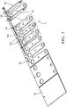
- FIG. 1 shows a perspective, view to a preassembled two-part electrical bus bar 10 attached on a carrier strip 20.
- the electrical bus bar 10 comprising: a first mounting portion 110 adapted to be connected to a first counter connector, a second mounting portion 120 adapted to be connected to a second counter connector and a flexible section 130 between the first and second mounting portions 110, 120.
- the bus bar 10 comprises at least a flat first part 140 and at least a flat second part 150.
- Each flat part 140, 50 extends from the first mounting portion 110 to the second mounting portion 120 and is arranged in a stacked configuration when the electrical bus bar is finalized, by folding the two flat parts.
- the flat first part 140 and the flat second part 150 is made of a metal sheet 30.
- a first stripe 180 of the metal sheet 30 extends from a body edge of the flat first part 140 to a body edge of the flat second part 150 forming a first link 181.
- the first link 181 is dimensioned to keep a first contact surface 142 of the flat first part 140 and a second contact surface 152 of the flat second part 150 in intimate contact, in the stacked configuration (see figure 5 ).
- the flat first part 140 comprises an arm 186, protruding from the first contact surface 142, located in the flexible section 130.
- the flat second part 150 comprises an opening 188 located in the flexible section 130.
- the arm 186 is also made from the metal sheet 30 e.g. by stamping.
- the arm 186 is formed to protrude into the opening, thereby limiting movement of the flat first part 140 in relation to the flat second part 150.
- the arm 186 protrudes through the opening 188.
- An arm end 187 is in contact to a third contact surface 154 of the flat second part 150 opposite to the second contact surface 152 to keep the first contact surface 142 of the flat first part 140 and the second contact surface 152 of the flat second part 150 in intimate contact.
- the cooperation of the flat parts 140, 50 is also shown in figure 5 .
- the electrical bus bar 10 has an elongated shape aligned along a longitudinal axis X, wherein the first link 181 is attached to the body edges of the first flat part 140 and the second flat part 150 at a positions where the body edges are substantially parallel to the longitudinal axis X.
- FIG 2 shows a perspective, view to a preassembled three-part electrical bus bar 10 attached on a carrier strip 20.
- the electrical bus bar 10 comprises a flat third part 160, extending from the first mounting portion 110 to the second mounting portion 120, made of the metal sheet 30 and arranged to the stacked configuration (when finalized of the flat first part 140 and the flat second part 150.
- a second strip 182 of the metal sheet 30 extends from a body edge of the flat first part 140 to a body edge of the flat third part 160 forming a second link 183.
- the flat third part 160 comprises a forth contact surface 162 that is in intimate contact with the third contact surface 154. The cooperation of the flat parts 140, 150, 160 is shown in figure 5 .
- the first link 181 and the second link 183 are attached to the body edges at positions where the body edges are parallel to the longitudinal axis X.
- the second link 183 is attached to the body edge of the first flat part 140 and to the body edge of the third flat part 160 at positions where the body edges are substantially parallel to the longitudinal axis X.
- the first link 181 and the second link 183 are arranged on positions, opposite to each other, along a transversal axis Y, perpendicular to the longitudinal axis X.
- the extension of the first link 181 is smaller than the extension of the second link 183.
- the flat third part 160 comprises a second opening 189 located in the flexible section 130.
- the arm 186 is formed to protrude into the second opening 189, thereby limiting movement of the flat first part 140 in relation to the flat second part 150 and the flat third part 160.
- Figure 3 and figure 4 show a perspective, view to a preassembled three-part electrical bus bar while manufacturing.
- the electrical bus bar 10 is made of one piece of metal sheet 30.
- the contact surfaces 142, 52, 54 can be plated with tin.
- the flat parts are attached to the carrier strip 20.
- the three flat parts are stamped from the metal sheet 30. Only the flat first part 140 stays connected to the carrier strip 20.
- the flat second part 150 is folded towards the flat first part 140 using the first link 181 as a hinge until the flat second part 150 touches the flat first part 140.
- the flat third part 160 is folded towards the flat second part 150 using the second link 183 as a hinge until the flat third part 160 touches the flat second part 140.
- the arm 186 protrudes through the first opening 189 and the second opening.
- the arm end 187 is the formed to touch the fifth contact surface 164. It may be necessary to deform the finally assembled bus bar 10 along the longitudinal axis X to fulfill the set requirements.
- Figure. 5 shows a perspective, view to a three-part electrical bus bar 10.
- the tree flat parts 140, 50, 50 are arranged in the stacked configuration.
- the first link 181 and the second link 183 are attached to the body edges at positions where the body edges are parallel to the longitudinal axis X.
- the second link 183 is attached to the body edge of the first flat part 140 and to the body edge of the third flat part 160 at positions where the body edges are parallel to the longitudinal axis X.
- the first link 181 and the second link 183 are arranged on positions, opposite to each other, along a transversal axis Y, perpendicular to the longitudinal axis X.
- the arm 186 protrudes through the second opening 189 and wherein the arm end 187 is in contact to a fifth contact surface 164 of the flat third part 160 opposite to the fourth contact surface 162 to keep the first contact surface 142 of the flat first part 140 and the second contact surface 152 of the flat second part 150, furthermore the third contact surface 154 of the flat second part 150 and the fourth contact surface 162 of the flat third part 160 in intimate contact.
- the first mounting portion 110 comprises a first connecting opening 210 and the second mounting portion 120 comprises a second connecting opening 220.
- Figure 6 shows a perspective, view to a three-part electrical bus bar 10 equipped with an electrical terminal 230.
- the second connecting opening 220 is equipped with the electrical terminal 230.
Landscapes
- Chemical & Material Sciences (AREA)
- Chemical Kinetics & Catalysis (AREA)
- Electrochemistry (AREA)
- General Chemical & Material Sciences (AREA)
- Engineering & Computer Science (AREA)
- Manufacturing & Machinery (AREA)
- Inorganic Chemistry (AREA)
- Multi-Conductor Connections (AREA)
- Connection Or Junction Boxes (AREA)
- Non-Insulated Conductors (AREA)
- Coupling Device And Connection With Printed Circuit (AREA)
Abstract
Description
- The invention relates to an electrical bus bar for high current application in electrical driven vehicles or hybrid vehicles. Furthermore, the invention relates to a method for manufacturing the electrical bus bar.
- Electrical connections employing bus bars are used in different types of connector systems. One application is an automotive application, such as for connection to a battery of a vehicle. In some applications, spacing around the battery, such as above the battery, in front of the battery, to one side or the other of the battery, may be limited. There may not be room for a bus bar to extend into such space, or there may not be room around the battery to get a tool for connecting the bus bar to the power terminal of the battery. Additionally, connecting and un-connecting the bus bar to the power terminal of the battery may be time consuming or require special, expensive tools. In some applications, two batteries need to be connected together in series or in parallel and a bus bar is needed to connect the power terminal of one battery to the power terminal of another battery. Problems arise in connecting one battery to another battery. For example, the spacing between the batteries may vary from application to application. The position tolerance has a wide range between any adjacent two batteries. Additionally, vibration may cause the batteries to move relative to one another.
- There is a need for a flexible connection in such applications. Solutions to increase flexibility of electrical connections are known in the art. The solutions usually use a high number of thin electrical conductors (multilayer assembly) that are arranged parallel to each other, to provide flexibility. On the other hand, when a bus bar is required to carry high currents, the thickness of the bus bar increases and manufacturing of such a bus bar is difficult and expensive. In some high current application, the tolerances of the system that need to be considered are in a narrow range, but still have to be taken into account. For such application the flexibility and the ability to carry current need to be balanced.
- Thus, there is the need in the art to provide an electrical bus bar for power applications in electric vehicles that provides a necessary amount of mechanical flexibility as well as the ability to carry high current between the power devices. Furthermore, an electrical bus bar that is easy and cheap to manufacture.
An electrical bus bar according claim1 and the method to manufacture the electrical bus bar according claim 15 solve these and other objects, which become apparent upon reading the following description. - The present application relates to an electrical bus bar comprising: a first mounting portion adapted to be connected to a first counter connector, a second mounting portion adapted to be connected to a second counter connector and a flexible section between the first and second mounting portions. The bus bar comprises at least a flat first part and at least a flat second part. Each flat part extends from the first mounting portion to the second mounting portion and is arranged in a stacked configuration. The flat first part and the flat second part is made of a metal sheet. A first stripe of the metal sheet extends from a body edge of the flat first part to a body edge of the flat second part forming a first link. The first link is dimensioned to keep a first contact surface of the flat first part and a second contact surface of the flat second part in intimate contact.
- The disclosed invention combines the advantages inflexibility of electrical bus bars having a high number of electric conductive layers with the high current properties of bus bars made of solid material. In some high current application, the tolerance, that has to be considered is e.g. in the range of 1-3 mm. The flexibility that is needed while assembling the bus bar into the vehicle is quite low. A bus bar made of three solid parts arranged parallel to each other provide little flexibility while assembling the bus bar. The solid flat parts are able to move very little in relation to each other. This little movement provides little flexibility. After assembling, the solid parts, in combination, provide the ability to carry high currents. The solid flat parts are linked with a metal stripe, extending from the edges, that keeps the flat parts in a stacked configuration. The link has a length that allows movement of the flat parts. The link acts as a hinge that allows to fold the linked flat parts. When the parts are arranged with the contact surfaces contacting each other, the link prevents movement that separate the contact surfaces. The links are preferable attached in the mounting portions. That keeps the electrical bus bar easy to handle.
- The present application discloses also a method for manufacturing an n electrical bus bar. The method comprises the steps:
- a) providing a metal sheet and a tooled stamping machine;
- b) inserting the metal sheet into the stamping machine;
- c) stamp the flat first part and flat second part thereby forming the arm and the opening;
- d) folding the flat first part and flat second part to a stacked configuration, whereby the firs link limits the movement of the flat first part and flat second part;
- e) Removing the carrier strip.
- According to a preferred embodiment, the flat first part comprises an arm, protruding from the first contact surface, located in the flexible section and wherein the flat second part comprises an opening located in the flexible section, wherein the arm is formed to protrude into the opening, thereby limiting movement of the flat first part in relation to the flat second part The arm protrudes into the opening and prevents movement of the flat parts in relation to each other. If more flexibility is requested, the opening can be designed slightly bigger than the cross-sectional farm. This provides little movement of the arm inside the opening. Hence, the flat parts can move a little bit more in relation to each other.
- Preferably, the arm protrudes through the opening and wherein an arm end is in contact to a third contact surface of the flat second part opposite to the second contact surface to keep the first contact surface of the flat first part and the second contact surface of the flat second part in intimate contact. The intimate contact reduces the electrical resistance of the electrical bus bar because the bus bar acts as a solid part. On the other hand, the flat parts can move little in relation to each other, when forced while assembly into the vehicle.
- Advantageously, the electrical bus bar is made of one piece of metal sheet. This reduces the costs for manufacturing the electrical bus bar
- Preferably, all contact surfaces are plated with tin. A combination of a tin plating for the bus bar and silver for a terminal works well in practice. The contact surfaces can be plated to prevent corrosion or to reduce electrical resistance.
- Advantageously, the electrical bus bar has an elongated shape aligned along a longitudinal axis, wherein the first link is attached to the body edges of the first flat part and the second flat part at a positions where the body edges are substantially parallel to the longitudinal axis. This embodiment enables the usage of very easy design for the first link. The link has to be just a straight strip of the sheet metal.
- Preferably, the electrical bus bar comprises a flat third part, extending from the first mounting portion to the second mounting portion, made of the metal sheet and arranged to the stacked configuration, wherein a second strip of the metal sheet extends from a body edge of the flat first part to a body edge of the flat third part forming a second link, wherein the flat third part comprises a forth contact surface that is in intimate contact with the third contact surface. The additional flat part improves, dependent on the requirements and dimensions, the electrical resistance or the flexibility.
- Preferably the first link and the second link are attached to the body edges at positions where the body edges are parallel to the longitudinal axis. This embodiment enables the usage of a very easy design for the first and second link. The links have to be just straight stripes of the sheet metal.
- In a preferred embodiment, the second link is attached to the body edge of the first flat part and to the body edge of the third flat part at positions where the body edges are substantially parallel to the longitudinal axis and wherein the first link and the second link are arranged on positions, opposite to each other, along a transversal axis, perpendicular to the longitudinal axis. The two links opposite to each other provide a stable fixation of the flat parts. The contact surfaces are kept in intimidate contact.
- Preferably, the extension of the first link is smaller than the extension of the second link. The first link is adapted to hold the first and second flat part, that are closer to each other, in position The second link is adapted to hold the first and third flat part, that have a distance to each other because the second flat part is in between, in position.
- Advantageously, the flat third part comprises a second opening located in the flexible section, wherein the arm is formed to protrude into the second opening, thereby limiting movement of the flat first part in relation to the flat second part and the flat third part. The arm protrudes into the opening and prevents movement of the flat parts in relation to each other. If more flexibility is requested, the opening can be designed slightly bigger than the cross-sectional of the arm. This provides little movement of the arm inside the opening. Hence, the flat parts can move a little bit more in relation to each other.
- Preferably, the arm protrudes through the second opening and wherein the arm end is in contact to a fifth contact surface of the flat third part opposite to the fourth contact surface to keep the first contact surface of the flat first part and the second contact surface of the flat second part, furthermore the third contact surface of the flat second part and the fourth contact surface of the flat third part in intimate contact. The intimate contact reduces the electrical resistance of the electrical bus bar because the bus bar acts as a solid part. On the other hand, the flat parts can move little in relation to each other, when forced while assembly into the vehicle.
- In a preferred embodiment, the first mounting portion comprises a first connecting opening and the second mounting portion comprises a second connecting opening. The openings receive bolts of high-power devises. The bolts are connected to the mounting portions by screw connections. The screw connections press the flat parts against each other and reduce this way the electrical resistance of the electrical bus bar.
- Advantageously, the at least one of the first connecting opening or the second connecting opening is equipped with an electrical terminal. The electrical terminal is pressed in the connector opening, thereby mechanically connecting the flat parts. The press-fit connection also provides a low resistant electrical connection between the flat parts and the electrical terminal.
- In the following, the invention is described exemplarily with reference to the enclosed figures, in which
- Fig. 1
- shows a perspective, view to a preassembled two-part electrical bus bar attached on a carrier strip;
- Fig. 2
- shows a perspective, view to a preassembled three-part electrical bus bar attached on a carrier strip;
- Fig. 3
- shows a perspective, view to a preassembled three-part electrical bus bar while manufacturing;
- Fig. 4
- shows a perspective, view to a preassembled three-part electrical bus bar while manufacturing;
- Fig. 5
- shows a perspective, view to a three-part electrical bus bar;
- Fig. 6
- shows a perspective, view to a three-part electrical bus bar equipped with an electrical terminal;
-
Figure 1 shows a perspective, view to a preassembled two-partelectrical bus bar 10 attached on acarrier strip 20. Theelectrical bus bar 10 comprising: a first mountingportion 110 adapted to be connected to a first counter connector, a second mountingportion 120 adapted to be connected to a second counter connector and aflexible section 130 between the first and second mountingportions bus bar 10 comprises at least a flatfirst part 140 and at least a flatsecond part 150. Eachflat part 140, 50 extends from the first mountingportion 110 to the second mountingportion 120 and is arranged in a stacked configuration when the electrical bus bar is finalized, by folding the two flat parts. The flatfirst part 140 and the flatsecond part 150 is made of ametal sheet 30. A first stripe 180 of themetal sheet 30 extends from a body edge of the flatfirst part 140 to a body edge of the flatsecond part 150 forming a first link 181. The first link 181 is dimensioned to keep afirst contact surface 142 of the flatfirst part 140 and asecond contact surface 152 of the flatsecond part 150 in intimate contact, in the stacked configuration (seefigure 5 ). The flatfirst part 140 comprises anarm 186, protruding from thefirst contact surface 142, located in theflexible section 130. The flatsecond part 150 comprises anopening 188 located in theflexible section 130. Thearm 186 is also made from themetal sheet 30 e.g. by stamping. Thearm 186 is formed to protrude into the opening, thereby limiting movement of the flatfirst part 140 in relation to the flatsecond part 150. Thearm 186 protrudes through theopening 188. Anarm end 187 is in contact to athird contact surface 154 of the flatsecond part 150 opposite to thesecond contact surface 152 to keep thefirst contact surface 142 of the flatfirst part 140 and thesecond contact surface 152 of the flatsecond part 150 in intimate contact. The cooperation of theflat parts 140, 50 is also shown infigure 5 . Theelectrical bus bar 10 has an elongated shape aligned along a longitudinal axis X, wherein the first link 181 is attached to the body edges of the firstflat part 140 and the secondflat part 150 at a positions where the body edges are substantially parallel to the longitudinal axis X. -
Figure 2 shows a perspective, view to a preassembled three-partelectrical bus bar 10 attached on acarrier strip 20. Theelectrical bus bar 10 comprises a flatthird part 160, extending from the first mountingportion 110 to the second mountingportion 120, made of themetal sheet 30 and arranged to the stacked configuration (when finalized of the flatfirst part 140 and the flatsecond part 150. A second strip 182 of themetal sheet 30 extends from a body edge of the flatfirst part 140 to a body edge of the flatthird part 160 forming a second link 183. The flatthird part 160 comprises aforth contact surface 162 that is in intimate contact with thethird contact surface 154. The cooperation of theflat parts figure 5 . The first link 181 and the second link 183 are attached to the body edges at positions where the body edges are parallel to the longitudinal axis X. The second link 183 is attached to the body edge of the firstflat part 140 and to the body edge of the thirdflat part 160 at positions where the body edges are substantially parallel to the longitudinal axis X. The first link 181 and the second link 183 are arranged on positions, opposite to each other, along a transversal axis Y, perpendicular to the longitudinal axis X. The extension of the first link 181 is smaller than the extension of the second link 183. The flatthird part 160 comprises asecond opening 189 located in theflexible section 130. Thearm 186 is formed to protrude into thesecond opening 189, thereby limiting movement of the flatfirst part 140 in relation to the flatsecond part 150 and the flatthird part 160. -
Figure 3 andfigure 4 show a perspective, view to a preassembled three-part electrical bus bar while manufacturing. Theelectrical bus bar 10 is made of one piece ofmetal sheet 30. The contact surfaces 142, 52, 54 can be plated with tin. Until finalization, the flat parts are attached to thecarrier strip 20. In a first production step, the three flat parts are stamped from themetal sheet 30. Only the flatfirst part 140 stays connected to thecarrier strip 20. In the next step, the flatsecond part 150 is folded towards the flatfirst part 140 using the first link 181 as a hinge until the flatsecond part 150 touches the flatfirst part 140. Than the flatthird part 160 is folded towards the flatsecond part 150 using the second link 183 as a hinge until the flatthird part 160 touches the flatsecond part 140. Thearm 186 protrudes through thefirst opening 189 and the second opening. Finally thearm end 187 is the formed to touch thefifth contact surface 164. It may be necessary to deform the finally assembledbus bar 10 along the longitudinal axis X to fulfill the set requirements. -
Figure. 5 shows a perspective, view to a three-partelectrical bus bar 10. The treeflat parts 140, 50, 50 are arranged in the stacked configuration. The first link 181 and the second link 183 are attached to the body edges at positions where the body edges are parallel to the longitudinal axis X. The second link 183 is attached to the body edge of the firstflat part 140 and to the body edge of the thirdflat part 160 at positions where the body edges are parallel to the longitudinal axis X. The first link 181 and the second link 183 are arranged on positions, opposite to each other, along a transversal axis Y, perpendicular to the longitudinal axis X. Thearm 186 protrudes through thesecond opening 189 and wherein thearm end 187 is in contact to afifth contact surface 164 of the flatthird part 160 opposite to thefourth contact surface 162 to keep thefirst contact surface 142 of the flatfirst part 140 and thesecond contact surface 152 of the flatsecond part 150, furthermore thethird contact surface 154 of the flatsecond part 150 and thefourth contact surface 162 of the flatthird part 160 in intimate contact. The first mountingportion 110 comprises a first connectingopening 210 and the second mountingportion 120 comprises a second connectingopening 220. -
Figure 6 shows a perspective, view to a three-partelectrical bus bar 10 equipped with anelectrical terminal 230. In this embodiment the second connectingopening 220 is equipped with theelectrical terminal 230.
Claims (15)
- An electrical bus bar (10) comprising: a first mounting portion (110) adapted to be connected to a first counter connector, a second mounting portion (120) adapted to be connected to a second counter connector and a flexible section (130) between the first and second mounting portions (110, 120), wherein the bus bar (10) comprises at least a flat first part (140) and at least a flat second part (150), wherein each flat part (140, 150) extends from the first mounting portion (110) to the second mounting portion (120) and is arranged in a stacked configuration, wherein the flat first part (140) and the flat second part (150) is made of a metal sheet (30), wherein a first stripe (180) of the metal sheet (30) extends from a body edge of the flat first part (140) to a body edge of the flat second part (150) forming a first link (181), wherein the first link (181) is dimensioned to keep a first contact surface (142) of the flat first part (140) and a second contact surface (152) of the flat second part (150) in intimate contact.
- An electrical bus bar (10) according to claim 1, wherein the flat first part (140) comprises an arm (186), protruding from the first contact surface (142), located in the flexible section (130) and wherein the flat second part (150) comprises an opening (188) located in the flexible section (130), wherein the arm (186) is formed to protrude into the opening, thereby limiting movement of the flat first part (140) in relation to the flat second part (150).
- An electrical bus bar (10) according to the preceding claim, wherein the arm (186) protrudes through the opening (188) and wherein an arm end (187) is in contact to a third contact surface (154) of the flat second part (150) opposite to the second contact surface (152) to keep the first contact surface (142) of the flat first part (140) and the second contact surface (152) of the flat second part (150) in intimate contact.
- An electrical bus bar (10) according to any preceding claim, wherein the electrical bus bar (10) is made of one piece of metal sheet (30).
- An electrical bus bar (10) according to any preceding claim, wherein all contact surfaces (142, 52, 54) are plated with tin.
- An electrical bus bar (10) according to any preceding claim, wherein the electrical bus bar (10) has an elongated shape aligned along a longitudinal axis (X), wherein the first link (181) is attached to the body edges of the first flat part (140) and the second flat part (150) at a positions where the body edges are substantially parallel to the longitudinal axis (X).
- An electrical bus bar (10) according to any preceding claim, wherein the electrical bus bar (10) comprises a flat third part (160), extending from the first mounting portion (110) to the second mounting portion (120), made of the metal sheet (30) and arranged to the stacked configuration, wherein a second strip (182) of the metal sheet (30) extends from a body edge of the flat first part (140) to a body edge of the flat third part (160) forming a second link (183), wherein the flat third part (160) comprises a forth contact surface (162) that is in intimate contact with the third contact surface (154).
- An electrical bus bar (10) according to claim 6 and claim 7, wherein the first link (181) and the second link (183) are attached to the body edges at positions where the body edges are parallel to the longitudinal axis (X).
- An electrical bus bar (10) according to the preceding claim, wherein the second link (183) is attached to the body edge of the first flat part (140) and to the body edge of the third flat part (160) at positions where the body edges are substantially parallel to the longitudinal axis (X) and wherein the first link (181) and the second link (183) are arranged on positions, opposite to each other, along a transversal axis (Y), perpendicular to the longitudinal axis (X).
- An electrical bus bar (10) according to any of claims 7 to 9, wherein the extension of the first link (181) is smaller than the extension of the second link (183).
- An electrical bus bar (10) according to claim2 in combination with any of claims 7 to 10, wherein the flat third part (160) comprises a second opening (189) located in the flexible section (130), wherein the arm (186) is formed to protrude into the second opening (189), thereby limiting movement of the flat first part (140) in relation to the flat second part (150) and the flat third part (160).
- An electrical bus bar (10) according to the preceding claim, wherein the arm (186) protrudes through the second opening (189) and wherein the arm end (187) is in contact to a fifth contact surface (164) of the flat third part (160) opposite to the fourth contact surface (162) to keep the first contact surface (142) of the flat first part (140) and the second contact surface (152) of the flat second part (150), furthermore the third contact surface (154) of the flat second part (150) and the fourth contact surface (162) of the flat third part (160) in intimate contact.
- An electrical bus bar (10) according to any preceding claim, wherein the first mounting portion (110) comprises a first connecting opening (210) and the second mounting portion (120) comprises a second connecting opening (220).
- An electrical bus bar (10) according to the preceding claim, wherein at least one of the first connecting opening (210) or the second connecting opening (220) is equipped with an electrical terminal (230).
- Method for manufacturing an n electrical bus bar (10) according to any of claims 1 to 6 comprising the steps:a) providing a metal sheet (30) and a tooled stamping machine;b) inserting the metal sheet (30) into the stamping machine;c) stamp the flat first part (140) and flat second part (140) thereby forming the arm (186) and the opening (188);d) folding the flat first part (140) and flat second part (140) to a stacked configuration, whereby the firs link (181) limits the movement of the flat first part (140) and flat second part (140);e) Removing the carrier strip (20).
Priority Applications (3)
| Application Number | Priority Date | Filing Date | Title |
|---|---|---|---|
| EP17207129.2A EP3499655B1 (en) | 2017-12-13 | 2017-12-13 | Electrical bus bar |
| US16/207,091 US10476217B2 (en) | 2017-12-13 | 2018-12-01 | Electrical bus bar |
| CN201811512053.6A CN109921244B (en) | 2017-12-13 | 2018-12-11 | Electric bus bars |
Applications Claiming Priority (1)
| Application Number | Priority Date | Filing Date | Title |
|---|---|---|---|
| EP17207129.2A EP3499655B1 (en) | 2017-12-13 | 2017-12-13 | Electrical bus bar |
Publications (2)
| Publication Number | Publication Date |
|---|---|
| EP3499655A1 true EP3499655A1 (en) | 2019-06-19 |
| EP3499655B1 EP3499655B1 (en) | 2021-03-31 |
Family
ID=60673405
Family Applications (1)
| Application Number | Title | Priority Date | Filing Date |
|---|---|---|---|
| EP17207129.2A Active EP3499655B1 (en) | 2017-12-13 | 2017-12-13 | Electrical bus bar |
Country Status (3)
| Country | Link |
|---|---|
| US (1) | US10476217B2 (en) |
| EP (1) | EP3499655B1 (en) |
| CN (1) | CN109921244B (en) |
Families Citing this family (11)
| Publication number | Priority date | Publication date | Assignee | Title |
|---|---|---|---|---|
| JP7016836B2 (en) * | 2019-06-10 | 2022-02-07 | 矢崎総業株式会社 | Conductive system |
| DE102019218953A1 (en) * | 2019-12-05 | 2021-06-10 | Robert Bosch Gmbh | Electronic circuit unit |
| US12401146B2 (en) * | 2019-12-12 | 2025-08-26 | Fci Usa Llc | Card-edge connector system with busbar connection for high-power applications |
| US10840611B1 (en) * | 2020-02-06 | 2020-11-17 | Aptive Technologies Limited | Electrical terminal and method of forming same |
| US11791597B2 (en) * | 2021-02-05 | 2023-10-17 | Aptiv Technologies (2) S.À R.L. | Flexible electrical bus bar and method of manufacturing the same |
| DE102022115344A1 (en) | 2022-06-21 | 2023-12-21 | Bayerische Motoren Werke Aktiengesellschaft | Cell contacting system and method for producing a cell contacting system |
| DE102022210548A1 (en) * | 2022-10-06 | 2024-04-11 | Zf Friedrichshafen Ag | Busbar for an electric drive |
| EP4354663B1 (en) * | 2022-10-13 | 2025-12-10 | AKNH Kontaktsysteme GmbH | Crimp connector for mechanical and electrically conductive connection of an electrical connection contact to an electrical conductor and crimped connection of an electrical connection contact with an electrical conductor |
| JP2024074356A (en) * | 2022-11-21 | 2024-05-31 | 株式会社オートネットワーク技術研究所 | Multilayer busbar and terminal block |
| USD1082698S1 (en) * | 2023-08-08 | 2025-07-08 | The Noco Company | Busbar for a battery |
| US20250260132A1 (en) * | 2024-02-08 | 2025-08-14 | Te Connectivity Solutions Gmbh | Contact Adapter, Busbar, Contacting System, Method of Contacting a Plurality of Batteries and Assembly Method for Creating a Plugged Battery Pack |
Citations (3)
| Publication number | Priority date | Publication date | Assignee | Title |
|---|---|---|---|---|
| CA892781A (en) * | 1972-02-08 | A. Elliott Howard | Spark plug terminal | |
| DE102011076624A1 (en) * | 2011-05-27 | 2012-11-29 | Elringklinger Ag | cell connectors |
| US20130000957A1 (en) * | 2010-04-22 | 2013-01-03 | Yazaki Corporation | Connection structure for a wiring member |
Family Cites Families (6)
| Publication number | Priority date | Publication date | Assignee | Title |
|---|---|---|---|---|
| US7229327B2 (en) * | 2005-05-25 | 2007-06-12 | Alcoa Fujikura Limited | Canted coil spring power terminal and sequence connection system |
| EP2441103B2 (en) * | 2009-06-08 | 2018-09-12 | Auto-Kabel Management GmbH | Battery cell connector |
| KR101222371B1 (en) * | 2010-11-12 | 2013-01-16 | 로베르트 보쉬 게엠베하 | Terminal of rechargeable battery, method of assembling the terminal of rechargeable battery, rechargeable battery module and method of assembling the same |
| DE102012202623A1 (en) * | 2012-02-21 | 2013-08-22 | Elringklinger Ag | cell connectors |
| JP5606481B2 (en) * | 2012-03-23 | 2014-10-15 | 株式会社東芝 | Assembled battery |
| KR20140140744A (en) * | 2013-05-30 | 2014-12-10 | 삼성에스디아이 주식회사 | Battery module |
-
2017
- 2017-12-13 EP EP17207129.2A patent/EP3499655B1/en active Active
-
2018
- 2018-12-01 US US16/207,091 patent/US10476217B2/en active Active
- 2018-12-11 CN CN201811512053.6A patent/CN109921244B/en active Active
Patent Citations (3)
| Publication number | Priority date | Publication date | Assignee | Title |
|---|---|---|---|---|
| CA892781A (en) * | 1972-02-08 | A. Elliott Howard | Spark plug terminal | |
| US20130000957A1 (en) * | 2010-04-22 | 2013-01-03 | Yazaki Corporation | Connection structure for a wiring member |
| DE102011076624A1 (en) * | 2011-05-27 | 2012-11-29 | Elringklinger Ag | cell connectors |
Also Published As
| Publication number | Publication date |
|---|---|
| EP3499655B1 (en) | 2021-03-31 |
| US20190181599A1 (en) | 2019-06-13 |
| US10476217B2 (en) | 2019-11-12 |
| CN109921244A (en) | 2019-06-21 |
| CN109921244B (en) | 2021-03-16 |
Similar Documents
| Publication | Publication Date | Title |
|---|---|---|
| EP3499655B1 (en) | Electrical bus bar | |
| EP2652841B1 (en) | Receptacle terminal | |
| EP2929596B1 (en) | Power terminal connector | |
| DE10330904B4 (en) | Connector assembly for electrical connection | |
| EP2517310B1 (en) | Power contact | |
| US8858274B2 (en) | Electric terminal | |
| CN103947048B (en) | Tuning fork electrical contact with non-rectangular tines and method of manufacturing the same | |
| JP5996009B2 (en) | Electrical center with bus for electric or hybrid electric vehicles | |
| EP1313179A2 (en) | Press-fit bus bar for distributing power | |
| EP3339104B1 (en) | A current transport mechanism, in particular an electrical or electromechanical current bar | |
| EP1947740B1 (en) | Electrical socket terminal having contact stabilizers | |
| CN118235300A (en) | Connector, connector assembly, and tool and method for assembling connector assembly | |
| US20060205267A1 (en) | Electrical connector and method of producing same | |
| US20110232960A1 (en) | Component-equipped-holder mounting structure | |
| EP1911129A1 (en) | Male electrical terminal | |
| CN108270093A (en) | Transmit connector, connection component and charging socket | |
| CN206313154U (en) | Transmission connector, coupling assembly and charging socket | |
| EP4518034B1 (en) | Terminal unit | |
| JP2024172226A (en) | Terminal Block Unit | |
| JP2017216212A (en) | Busbar connection structure | |
| EP4348770A1 (en) | A tubular high current female terminal |
Legal Events
| Date | Code | Title | Description |
|---|---|---|---|
| PUAI | Public reference made under article 153(3) epc to a published international application that has entered the european phase |
Free format text: ORIGINAL CODE: 0009012 |
|
| STAA | Information on the status of an ep patent application or granted ep patent |
Free format text: STATUS: THE APPLICATION HAS BEEN PUBLISHED |
|
| AK | Designated contracting states |
Kind code of ref document: A1 Designated state(s): AL AT BE BG CH CY CZ DE DK EE ES FI FR GB GR HR HU IE IS IT LI LT LU LV MC MK MT NL NO PL PT RO RS SE SI SK SM TR |
|
| AX | Request for extension of the european patent |
Extension state: BA ME |
|
| STAA | Information on the status of an ep patent application or granted ep patent |
Free format text: STATUS: REQUEST FOR EXAMINATION WAS MADE |
|
| 17P | Request for examination filed |
Effective date: 20191219 |
|
| RBV | Designated contracting states (corrected) |
Designated state(s): AL AT BE BG CH CY CZ DE DK EE ES FI FR GB GR HR HU IE IS IT LI LT LU LV MC MK MT NL NO PL PT RO RS SE SI SK SM TR |
|
| GRAP | Despatch of communication of intention to grant a patent |
Free format text: ORIGINAL CODE: EPIDOSNIGR1 |
|
| STAA | Information on the status of an ep patent application or granted ep patent |
Free format text: STATUS: GRANT OF PATENT IS INTENDED |
|
| RIC1 | Information provided on ipc code assigned before grant |
Ipc: H01R 43/16 20060101AFI20201012BHEP Ipc: H01R 13/11 20060101ALN20201012BHEP Ipc: H02G 5/00 20060101ALN20201012BHEP Ipc: H01M 2/20 20060101ALN20201012BHEP |
|
| INTG | Intention to grant announced |
Effective date: 20201028 |
|
| GRAS | Grant fee paid |
Free format text: ORIGINAL CODE: EPIDOSNIGR3 |
|
| GRAA | (expected) grant |
Free format text: ORIGINAL CODE: 0009210 |
|
| STAA | Information on the status of an ep patent application or granted ep patent |
Free format text: STATUS: THE PATENT HAS BEEN GRANTED |
|
| AK | Designated contracting states |
Kind code of ref document: B1 Designated state(s): AL AT BE BG CH CY CZ DE DK EE ES FI FR GB GR HR HU IE IS IT LI LT LU LV MC MK MT NL NO PL PT RO RS SE SI SK SM TR |
|
| REG | Reference to a national code |
Ref country code: GB Ref legal event code: FG4D Ref country code: CH Ref legal event code: EP |
|
| REG | Reference to a national code |
Ref country code: DE Ref legal event code: R096 Ref document number: 602017035597 Country of ref document: DE Ref country code: AT Ref legal event code: REF Ref document number: 1378002 Country of ref document: AT Kind code of ref document: T Effective date: 20210415 |
|
| REG | Reference to a national code |
Ref country code: IE Ref legal event code: FG4D |
|
| REG | Reference to a national code |
Ref country code: LT Ref legal event code: MG9D |
|
| PG25 | Lapsed in a contracting state [announced via postgrant information from national office to epo] |
Ref country code: HR Free format text: LAPSE BECAUSE OF FAILURE TO SUBMIT A TRANSLATION OF THE DESCRIPTION OR TO PAY THE FEE WITHIN THE PRESCRIBED TIME-LIMIT Effective date: 20210331 Ref country code: FI Free format text: LAPSE BECAUSE OF FAILURE TO SUBMIT A TRANSLATION OF THE DESCRIPTION OR TO PAY THE FEE WITHIN THE PRESCRIBED TIME-LIMIT Effective date: 20210331 Ref country code: NO Free format text: LAPSE BECAUSE OF FAILURE TO SUBMIT A TRANSLATION OF THE DESCRIPTION OR TO PAY THE FEE WITHIN THE PRESCRIBED TIME-LIMIT Effective date: 20210630 Ref country code: BG Free format text: LAPSE BECAUSE OF FAILURE TO SUBMIT A TRANSLATION OF THE DESCRIPTION OR TO PAY THE FEE WITHIN THE PRESCRIBED TIME-LIMIT Effective date: 20210630 |
|
| PG25 | Lapsed in a contracting state [announced via postgrant information from national office to epo] |
Ref country code: LV Free format text: LAPSE BECAUSE OF FAILURE TO SUBMIT A TRANSLATION OF THE DESCRIPTION OR TO PAY THE FEE WITHIN THE PRESCRIBED TIME-LIMIT Effective date: 20210331 Ref country code: RS Free format text: LAPSE BECAUSE OF FAILURE TO SUBMIT A TRANSLATION OF THE DESCRIPTION OR TO PAY THE FEE WITHIN THE PRESCRIBED TIME-LIMIT Effective date: 20210331 Ref country code: SE Free format text: LAPSE BECAUSE OF FAILURE TO SUBMIT A TRANSLATION OF THE DESCRIPTION OR TO PAY THE FEE WITHIN THE PRESCRIBED TIME-LIMIT Effective date: 20210331 |
|
| REG | Reference to a national code |
Ref country code: NL Ref legal event code: MP Effective date: 20210331 |
|
| REG | Reference to a national code |
Ref country code: AT Ref legal event code: MK05 Ref document number: 1378002 Country of ref document: AT Kind code of ref document: T Effective date: 20210331 |
|
| PG25 | Lapsed in a contracting state [announced via postgrant information from national office to epo] |
Ref country code: LT Free format text: LAPSE BECAUSE OF FAILURE TO SUBMIT A TRANSLATION OF THE DESCRIPTION OR TO PAY THE FEE WITHIN THE PRESCRIBED TIME-LIMIT Effective date: 20210331 Ref country code: EE Free format text: LAPSE BECAUSE OF FAILURE TO SUBMIT A TRANSLATION OF THE DESCRIPTION OR TO PAY THE FEE WITHIN THE PRESCRIBED TIME-LIMIT Effective date: 20210331 Ref country code: CZ Free format text: LAPSE BECAUSE OF FAILURE TO SUBMIT A TRANSLATION OF THE DESCRIPTION OR TO PAY THE FEE WITHIN THE PRESCRIBED TIME-LIMIT Effective date: 20210331 Ref country code: AT Free format text: LAPSE BECAUSE OF FAILURE TO SUBMIT A TRANSLATION OF THE DESCRIPTION OR TO PAY THE FEE WITHIN THE PRESCRIBED TIME-LIMIT Effective date: 20210331 Ref country code: NL Free format text: LAPSE BECAUSE OF FAILURE TO SUBMIT A TRANSLATION OF THE DESCRIPTION OR TO PAY THE FEE WITHIN THE PRESCRIBED TIME-LIMIT Effective date: 20210331 Ref country code: SM Free format text: LAPSE BECAUSE OF FAILURE TO SUBMIT A TRANSLATION OF THE DESCRIPTION OR TO PAY THE FEE WITHIN THE PRESCRIBED TIME-LIMIT Effective date: 20210331 |
|
| PG25 | Lapsed in a contracting state [announced via postgrant information from national office to epo] |
Ref country code: IS Free format text: LAPSE BECAUSE OF FAILURE TO SUBMIT A TRANSLATION OF THE DESCRIPTION OR TO PAY THE FEE WITHIN THE PRESCRIBED TIME-LIMIT Effective date: 20210731 Ref country code: SK Free format text: LAPSE BECAUSE OF FAILURE TO SUBMIT A TRANSLATION OF THE DESCRIPTION OR TO PAY THE FEE WITHIN THE PRESCRIBED TIME-LIMIT Effective date: 20210331 Ref country code: RO Free format text: LAPSE BECAUSE OF FAILURE TO SUBMIT A TRANSLATION OF THE DESCRIPTION OR TO PAY THE FEE WITHIN THE PRESCRIBED TIME-LIMIT Effective date: 20210331 Ref country code: PT Free format text: LAPSE BECAUSE OF FAILURE TO SUBMIT A TRANSLATION OF THE DESCRIPTION OR TO PAY THE FEE WITHIN THE PRESCRIBED TIME-LIMIT Effective date: 20210802 Ref country code: PL Free format text: LAPSE BECAUSE OF FAILURE TO SUBMIT A TRANSLATION OF THE DESCRIPTION OR TO PAY THE FEE WITHIN THE PRESCRIBED TIME-LIMIT Effective date: 20210331 |
|
| REG | Reference to a national code |
Ref country code: DE Ref legal event code: R097 Ref document number: 602017035597 Country of ref document: DE |
|
| PG25 | Lapsed in a contracting state [announced via postgrant information from national office to epo] |
Ref country code: ES Free format text: LAPSE BECAUSE OF FAILURE TO SUBMIT A TRANSLATION OF THE DESCRIPTION OR TO PAY THE FEE WITHIN THE PRESCRIBED TIME-LIMIT Effective date: 20210331 Ref country code: DK Free format text: LAPSE BECAUSE OF FAILURE TO SUBMIT A TRANSLATION OF THE DESCRIPTION OR TO PAY THE FEE WITHIN THE PRESCRIBED TIME-LIMIT Effective date: 20210331 Ref country code: AL Free format text: LAPSE BECAUSE OF FAILURE TO SUBMIT A TRANSLATION OF THE DESCRIPTION OR TO PAY THE FEE WITHIN THE PRESCRIBED TIME-LIMIT Effective date: 20210331 |
|
| PLBE | No opposition filed within time limit |
Free format text: ORIGINAL CODE: 0009261 |
|
| STAA | Information on the status of an ep patent application or granted ep patent |
Free format text: STATUS: NO OPPOSITION FILED WITHIN TIME LIMIT |
|
| 26N | No opposition filed |
Effective date: 20220104 |
|
| PG25 | Lapsed in a contracting state [announced via postgrant information from national office to epo] |
Ref country code: IS Free format text: LAPSE BECAUSE OF FAILURE TO SUBMIT A TRANSLATION OF THE DESCRIPTION OR TO PAY THE FEE WITHIN THE PRESCRIBED TIME-LIMIT Effective date: 20210731 |
|
| PG25 | Lapsed in a contracting state [announced via postgrant information from national office to epo] |
Ref country code: MC Free format text: LAPSE BECAUSE OF FAILURE TO SUBMIT A TRANSLATION OF THE DESCRIPTION OR TO PAY THE FEE WITHIN THE PRESCRIBED TIME-LIMIT Effective date: 20210331 Ref country code: IT Free format text: LAPSE BECAUSE OF FAILURE TO SUBMIT A TRANSLATION OF THE DESCRIPTION OR TO PAY THE FEE WITHIN THE PRESCRIBED TIME-LIMIT Effective date: 20210331 |
|
| REG | Reference to a national code |
Ref country code: CH Ref legal event code: PL |
|
| REG | Reference to a national code |
Ref country code: BE Ref legal event code: MM Effective date: 20211231 |
|
| PG25 | Lapsed in a contracting state [announced via postgrant information from national office to epo] |
Ref country code: LU Free format text: LAPSE BECAUSE OF NON-PAYMENT OF DUE FEES Effective date: 20211213 Ref country code: IE Free format text: LAPSE BECAUSE OF NON-PAYMENT OF DUE FEES Effective date: 20211213 |
|
| PG25 | Lapsed in a contracting state [announced via postgrant information from national office to epo] |
Ref country code: BE Free format text: LAPSE BECAUSE OF NON-PAYMENT OF DUE FEES Effective date: 20211231 |
|
| PG25 | Lapsed in a contracting state [announced via postgrant information from national office to epo] |
Ref country code: LI Free format text: LAPSE BECAUSE OF NON-PAYMENT OF DUE FEES Effective date: 20211231 Ref country code: CH Free format text: LAPSE BECAUSE OF NON-PAYMENT OF DUE FEES Effective date: 20211231 |
|
| P01 | Opt-out of the competence of the unified patent court (upc) registered |
Effective date: 20230420 |
|
| PG25 | Lapsed in a contracting state [announced via postgrant information from national office to epo] |
Ref country code: CY Free format text: LAPSE BECAUSE OF FAILURE TO SUBMIT A TRANSLATION OF THE DESCRIPTION OR TO PAY THE FEE WITHIN THE PRESCRIBED TIME-LIMIT Effective date: 20210331 |
|
| PG25 | Lapsed in a contracting state [announced via postgrant information from national office to epo] |
Ref country code: HU Free format text: LAPSE BECAUSE OF FAILURE TO SUBMIT A TRANSLATION OF THE DESCRIPTION OR TO PAY THE FEE WITHIN THE PRESCRIBED TIME-LIMIT; INVALID AB INITIO Effective date: 20171213 Ref country code: GR Free format text: LAPSE BECAUSE OF FAILURE TO SUBMIT A TRANSLATION OF THE DESCRIPTION OR TO PAY THE FEE WITHIN THE PRESCRIBED TIME-LIMIT Effective date: 20210331 |
|
| PG25 | Lapsed in a contracting state [announced via postgrant information from national office to epo] |
Ref country code: MK Free format text: LAPSE BECAUSE OF FAILURE TO SUBMIT A TRANSLATION OF THE DESCRIPTION OR TO PAY THE FEE WITHIN THE PRESCRIBED TIME-LIMIT Effective date: 20210331 |
|
| PG25 | Lapsed in a contracting state [announced via postgrant information from national office to epo] |
Ref country code: MT Free format text: LAPSE BECAUSE OF FAILURE TO SUBMIT A TRANSLATION OF THE DESCRIPTION OR TO PAY THE FEE WITHIN THE PRESCRIBED TIME-LIMIT Effective date: 20210331 |
|
| REG | Reference to a national code |
Ref country code: DE Ref legal event code: R081 Ref document number: 602017035597 Country of ref document: DE Owner name: APTIV TECHNOLOGIES AG, CH Free format text: FORMER OWNER: APTIV TECHNOLOGIES LIMITED, ST. MICHAEL, BB |
|
| PG25 | Lapsed in a contracting state [announced via postgrant information from national office to epo] |
Ref country code: TR Free format text: LAPSE BECAUSE OF FAILURE TO SUBMIT A TRANSLATION OF THE DESCRIPTION OR TO PAY THE FEE WITHIN THE PRESCRIBED TIME-LIMIT Effective date: 20210331 |
|
| PGFP | Annual fee paid to national office [announced via postgrant information from national office to epo] |
Ref country code: DE Payment date: 20251117 Year of fee payment: 9 |
|
| PGFP | Annual fee paid to national office [announced via postgrant information from national office to epo] |
Ref country code: GB Payment date: 20251107 Year of fee payment: 9 |
|
| PGFP | Annual fee paid to national office [announced via postgrant information from national office to epo] |
Ref country code: FR Payment date: 20251112 Year of fee payment: 9 |