EP3499462A1 - Line-of-sight detection device - Google Patents
Line-of-sight detection device Download PDFInfo
- Publication number
- EP3499462A1 EP3499462A1 EP17839579.4A EP17839579A EP3499462A1 EP 3499462 A1 EP3499462 A1 EP 3499462A1 EP 17839579 A EP17839579 A EP 17839579A EP 3499462 A1 EP3499462 A1 EP 3499462A1
- Authority
- EP
- European Patent Office
- Prior art keywords
- optical axis
- pupil
- line
- image
- eye
- Prior art date
- Legal status (The legal status is an assumption and is not a legal conclusion. Google has not performed a legal analysis and makes no representation as to the accuracy of the status listed.)
- Granted
Links
Images









Classifications
-
- G—PHYSICS
- G06—COMPUTING OR CALCULATING; COUNTING
- G06T—IMAGE DATA PROCESSING OR GENERATION, IN GENERAL
- G06T7/00—Image analysis
- G06T7/70—Determining position or orientation of objects or cameras
- G06T7/73—Determining position or orientation of objects or cameras using feature-based methods
-
- G—PHYSICS
- G06—COMPUTING OR CALCULATING; COUNTING
- G06T—IMAGE DATA PROCESSING OR GENERATION, IN GENERAL
- G06T7/00—Image analysis
- G06T7/70—Determining position or orientation of objects or cameras
- G06T7/73—Determining position or orientation of objects or cameras using feature-based methods
- G06T7/74—Determining position or orientation of objects or cameras using feature-based methods involving reference images or patches
-
- A—HUMAN NECESSITIES
- A61—MEDICAL OR VETERINARY SCIENCE; HYGIENE
- A61B—DIAGNOSIS; SURGERY; IDENTIFICATION
- A61B3/00—Apparatus for testing the eyes; Instruments for examining the eyes
- A61B3/10—Objective types, i.e. instruments for examining the eyes independent of the patients' perceptions or reactions
- A61B3/113—Objective types, i.e. instruments for examining the eyes independent of the patients' perceptions or reactions for determining or recording eye movement
-
- G—PHYSICS
- G06—COMPUTING OR CALCULATING; COUNTING
- G06F—ELECTRIC DIGITAL DATA PROCESSING
- G06F3/00—Input arrangements for transferring data to be processed into a form capable of being handled by the computer; Output arrangements for transferring data from processing unit to output unit, e.g. interface arrangements
- G06F3/01—Input arrangements or combined input and output arrangements for interaction between user and computer
- G06F3/03—Arrangements for converting the position or the displacement of a member into a coded form
- G06F3/033—Pointing devices displaced or positioned by the user, e.g. mice, trackballs, pens or joysticks; Accessories therefor
- G06F3/0346—Pointing devices displaced or positioned by the user, e.g. mice, trackballs, pens or joysticks; Accessories therefor with detection of the device orientation or free movement in a three-dimensional [3D] space, e.g. 3D mice, 6-DOF [six degrees of freedom] pointers using gyroscopes, accelerometers or tilt-sensors
-
- G—PHYSICS
- G06—COMPUTING OR CALCULATING; COUNTING
- G06T—IMAGE DATA PROCESSING OR GENERATION, IN GENERAL
- G06T7/00—Image analysis
- G06T7/50—Depth or shape recovery
- G06T7/55—Depth or shape recovery from multiple images
- G06T7/593—Depth or shape recovery from multiple images from stereo images
-
- G—PHYSICS
- G06—COMPUTING OR CALCULATING; COUNTING
- G06T—IMAGE DATA PROCESSING OR GENERATION, IN GENERAL
- G06T7/00—Image analysis
- G06T7/70—Determining position or orientation of objects or cameras
-
- G—PHYSICS
- G06—COMPUTING OR CALCULATING; COUNTING
- G06T—IMAGE DATA PROCESSING OR GENERATION, IN GENERAL
- G06T7/00—Image analysis
- G06T7/80—Analysis of captured images to determine intrinsic or extrinsic camera parameters, i.e. camera calibration
-
- G—PHYSICS
- G06—COMPUTING OR CALCULATING; COUNTING
- G06T—IMAGE DATA PROCESSING OR GENERATION, IN GENERAL
- G06T2207/00—Indexing scheme for image analysis or image enhancement
- G06T2207/30—Subject of image; Context of image processing
- G06T2207/30196—Human being; Person
- G06T2207/30201—Face
Definitions
- One aspect of the present invention relates to a line-of-sight detection device.
- the line-of-sight detection device uses a detection method called a "pupil-corneal reflection method".
- a detection method called a "pupil-corneal reflection method”.
- the line-of-sight direction is obtained using this change in positional relationship.
- the subject is caused to gaze at a visual target of which the coordinates are known.
- the pupil-corneal reflection method has an advantage that accuracy of the line-of-sight detection is high.
- Patent Literature 1 discloses a line-of-sight detection device using a pupil-corneal reflection method.
- the line-of-sight detection device has two or more video cameras subjected to camera calibration (stereo calibration). Each camera includes a near infrared light source. A configuration including the camera and the near-infrared light source is simply referred to as an optical system.
- the line-of-sight detection device obtains an image using each camera while controlling the near-infrared light source such that the near-infrared light source is lit.
- the line-of-sight detection device obtains the coordinates of a pupil and the coordinates of the corneal reflection of the light source using the acquired image.
- the line-of-sight detection device obtains a line-of-sight direction using relative positional coordinates between these.
- the line-of-sight detection device can detect a highly accurate gazing point through acquisition of three-dimensional coordinates of the pupil, accurate acquisition of a distance from each camera to the pupil, and calibration of a corneal reflection-pupil center vector which changes according to a change in distance.
- the eye-line-of-sight detection device of Patent Literature 1 needs a three-dimensional position of the pupil. Therefore, the pupil needs to be included in a plurality of images obtained by two or more cameras. Further, the pupil and the corneal reflection need to be included in at least one image to determine a line of sight angle.
- Patent Literature 1 Japanese Unexamined Patent Publication No. 2005-185431
- a line-of-sight angle range in which the corneal reflection can be obtained differs greatly among subjects.
- the line-of-sight angle range is equal to or greater than about 30 degrees and smaller than or equal to about 40 degrees.
- the angle range in which the line-of-sight direction can be detected tends to be limited.
- a line-of-sight detection device of the related art a light source is attached to a camera. According to this configuration, when the subject looks in a direction greatly deviated with respect to a direction directed to the camera, a state in which a corneal reflection does not appear may arise. Therefore, in the pupil-corneal reflection method using corneal reflection, it is difficult to extend the range in which the line of sight can be detected.
- the present invention provides a line-of-sight detection device capable of extending a detection range of a line-of-sight direction of a subject.
- a line-of-sight detection device includes an image acquisition unit that obtains a plurality of eye images including eyes of a subject; a light source that is disposed near the image acquisition unit and irradiates the subject with light for causing corneal reflection in the eye; and an image processing unit that acquires information on a pupil shape of the eye, a position (P S ) of a pupil center and a position (G S ) of corneal reflection included in the plurality of eye images using the plurality of eye images, and obtains a line of sight of the subject based on the acquired information, wherein the image processing unit includes a first optical axis acquisition unit that acquires a first optical axis candidate using the position (P S ) of the pupil center and the position (G S ) of the corneal reflection; a second optical axis acquisition unit that acquires a second optical axis candidate by using the pupil shape; an optical axis information acquisition unit that generates information for acquiring the optical axis using at least one of the
- the line-of-sight detection device includes the first optical axis acquisition unit and the second optical axis acquisition unit.
- the first optical axis acquisition unit obtains the optical axis using the position (P S ) of the pupil center and the position (G S ) of the corneal reflection. Therefore, the first optical axis acquisition unit can detect the line of sight in the range of the line of sight in which the corneal reflection can be obtained.
- the second optical axis acquisition unit obtains the optical axis using the shape of the pupil. Therefore, the second optical axis acquisition unit can detect the line of sight even in the range of the line of sight in which the corneal reflection cannot be obtained.
- the optical axis information acquisition unit generates information for selecting any one of the first optical axis candidate and the second optical axis candidate using the shape of the pupil.
- a deviation of the optical axis selected from the first optical axis candidate and the second optical axis candidate with respect to the visual axis is calibrated in the line-of-sight acquisition unit.
- the visual axis as a line of sight can be obtained. Therefore, the line-of-sight detection device can extend the range in which the line of sight can be satisfactorily detected, from a narrow range in which the corneal reflection can be obtained to a wide range in which the corneal reflection cannot be obtained.
- the calibration information may be a deviation angle ( ⁇ 0 ), and the deviation angle ( ⁇ 0 ) may be a vector indicating a deviation of the optical axis with respect to the visual axis, and may be indicated by a magnitude (
- the first optical axis candidate can be suitably obtained in the first optical axis acquisition unit. Further, the second optical axis candidate can be suitably obtained in the second optical axis acquisition unit.
- the first optical axis acquisition unit may associate the magnitude (
- the image acquisition unit may include a first camera that obtains a first eye image included in the plurality of eye images and that is disposed at a first camera position (O S1 ), and a second camera that obtains a second eye image included in the plurality of eye images and that is disposed at a second camera position (O S2 ),
- the eye may include a first eye and a second eye
- the first eye may include a position (G S1 ) of first corneal reflection, a position (P S1 ) of a first pupil center, and a first optical axis
- the second eye may include a position (G S2 ) of second corneal reflection, a position (P S2 ) of a second pupil center, and a second optical axis
- the image processing unit may further include a sixth computation unit that obtains information on a first virtual optical axis plane including the first camera position (O S1 ), the position (P S1 ) of the first pupil center, and a position at which the first optical axis intersect
- the line of sight and the first coefficient (k 1 , k 2 ) are obtained. Therefore, it becomes possible to sequentially update the first coefficient (k 1 , k 2 ). As a result, it is possible to improve accuracy of conversion of the magnitude (
- the second optical axis acquisition unit may associate an inverse cosine component of a reciprocal of the ellipticity (R) with the magnitude ( ⁇ ) of the angle ( ⁇ ) using a second coefficient (h).
- a second coefficient (h) it is possible to suitably convert the ellipticity (R) to the magnitude (
- the second optical axis acquisition unit may use a corrected ellipticity (R') obtained by correcting the deviation of a pupil contour caused by refraction of a cornea of an eyeball of the subject in acquisition of the magnitude (
- R' corrected ellipticity
- the eye may include a first eye and a second eye
- the image processing unit may further include a coordinate acquisition unit that acquires respective three-dimensional coordinates of a position (P S1 ) of the pupil center in the first eye, a position (P S2 ) of the pupil center in the second eye, a position (N S1 ) of a first nostril among a pair of nostrils of the subject, and a position (N S2 ) of a second nostril among the pair of nostrils of the subject; and a face posture acquisition unit that acquires a face posture of the subject using the position (P S1 ) of the pupil center, the position (P S2 ) of the pupil center, the position (N S1 ) of the first nostril, and the position (N S2 ) of the second nostril.
- the image acquisition unit may include a first camera that obtains a first image including a face of the subject, and a second camera that is disposed at a position separated from the first camera and obtains a second image including the face of the subject, and the coordinate acquisition unit may acquire the respective three-dimensional coordinates of the position (P S1 ) of the pupil center in the first eye, the position (P S2 ) of the pupil center in the second eye, the position (N S1 ) of the first nostril, and the position (N S2 ) of the second nostril using a stereo matching method based on the first image and the second image.
- the image acquisition unit may include one third camera that obtains a third image including a face of the subject, and the coordinate acquisition unit may include a distance computation unit that calculates a distance between three feature points generated from the first eye, the second eye, the first nostril, and the second nostril; a two-dimensional coordinate computation unit that calculates two-dimensional coordinates regarding three feature points in the third image using the third image acquired by the third camera; and a three-dimensional coordinate computation unit that calculates three-dimensional coordinates of each of the three generated feature points using the distance acquired by the distance computation unit and the two-dimensional coordinates acquired by the coordinate acquisition unit.
- the optical axis information acquisition unit may generate information for selecting one of the first optical axis candidate and the second optical axis candidate as the optical axis on the basis of the pupil shape. According to this configuration, it is possible to select one of the first optical axis candidate and the second optical axis candidate as the optical axis.
- a line-of-sight detection device capable of extending a detection range of a line-of-sight direction of a subject can be provided.
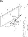
- a line-of-sight detection device 1 is a computer system that detects a line-of-sight direction of a subject M viewing a display device 30.
- the line-of-sight detection device 1 images eyes of the subject M with an optical system 15.
- the optical system 15 includes a camera 10 (an image acquisition unit, a first camera, a second camera, or a third camera) and a light source 13.
- the line-of-sight detection device 1 detects the line-of-sight direction of the subject M using an image processing device 20 (an image processing unit).
- the subject M is a person who is a target of detection of the line-of-sight direction. That is, the subject M is a target person.
- the line-of-sight detection device 1 can be used for, for example, a diagnosis device for detection of approximate driving, confirmation of a safety confirmation operation of a side mirror and a rearview mirror of a driver, detection of drowsiness of the driver, investigation of a degree of interest in a product, data input to a computer which is used for an amusement device or the like, diagnosis of autism in infants, and the like.
- the first line-of-sight detection process is a corneal reflection-pupil center method.
- the corneal reflection-pupil center method is selected when the subject M is viewing a visual target A1 displayed at a position close to the camera 10.
- the second line of sight detection process is a pupil shape method.
- the pupil shape method is selected when the subject M is viewing a visual target A2 displayed at a position far from the camera 10.
- the line of sight is a line connecting a position P S of the pupil center of the subject M to a gazing point of the subject M.
- the "gazing point” is a point that the subject M views.
- the term “line of sight” includes a meaning (concept) of a start point, an end point, and a direction.
- a "line-of-sight vector” indicates the line-of-sight direction of the subject M.
- the "line-of-sight vector” is one form expressing the "line-of-sight direction”.
- An output destination of the line-of-sight direction which is a detection result of the image processing device 20 is not limited at all.
- the image processing device 20 may display the determination result on a monitor with an image, a graphic, or text. Further, the image processing device 20 may store the determination result in a storage device such as a memory or a database. Further, the image processing device 20 may transmit the determination result to another computer system via a communication network.
- FIG. 2 illustrates the subject M, the camera 10, the display device 30, a virtual viewpoint plane VS, and an image example S G .
- a gazing point Q is shown in the display device 30 .
- a gazing point T is shown in the virtual viewpoint plane VS.
- the virtual viewpoint plane VS is a virtual plane having a camera-pupil center vector OP (a first vector) to be described below as a normal.
- the image example S G is an example of a high-resolution image including the pupil P of the subject M.
- the pupil P and a corneal reflection G are shown.
- the camera-pupil center vector OP is directed from the position P S of the pupil center to a position O S of the camera.
- a line-of-sight vector PQ is directed from the position P S of the pupil center to the position (Qs) of the gazing point Q.
- the line-of-sight vector PT is directed from the position P S of the pupil center to a position T S of the gazing point T.
- the line-of-sight vector PT is obtained as a line of sight.
- a corneal reflection-pupil center vector r (a second vector) shown in the image example S G is directed from a position G S of the corneal reflection to a position P S of the pupil center.
- the corneal reflection-pupil center vector r is based on an assumption that the position G S of the corneal reflection and the position P S of the pupil center exist on a common XY plane.
- the slope ⁇ is a rotation angle around the camera-pupil center vector OP in the virtual viewpoint plane VS.
- the slope ⁇ is a slope of a straight line passing through the position O S of the camera and the position T S of the gazing point T with respect to the horizontal axis X'.
- the slope ⁇ is a planar angle in the virtual viewpoint plane VS.
- the slope ⁇ is a scalar with magnitude
- An angle ⁇ is an angle formed by the camera-pupil center vector OP and the line-of-sight vector PQ.
- the angle ⁇ is a three-dimensional angle in a three-dimensional space.
- the angle ⁇ indicates one straight line (line of sight) using the magnitude
- a slope ⁇ ' shown in the image example S G is an angle formed by the corneal reflection-pupil center vector r and the horizontal axis X' on an image plane.
- the slope ⁇ ' is a planar angle on the image plane.
- the slope ⁇ ' is a scalar having a magnitude
- the first assumption is shown in Equation (1).
- the angle ⁇ is indicated by the magnitude
- a first coefficient k is a predetermined constant.
- the second assumption is shown in Equation (3).
- the second assumption is a relationship in which the slope ⁇ in the virtual viewpoint plane VS is equal to the slope ⁇ ' in an image including the pupil P.
- ⁇ ⁇ ′ (
- the corneal reflection-pupil center vector r is obtained from the image example S G acquired by the camera 10. According to the magnitude
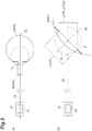
- FIG. 3(a) illustrates an eyeball 50 of the subject M when the subject M is viewing the optical system 15 including the camera 10.
- FIG. 3(b) illustrates the eyeball 50 of the subject M when the subject M is viewing a place different from the optical system 15.
- the eyeball 50 of the subject M is at infinity from the optical system 15 including the camera 10.
- a shape of the pupil P in the image obtained from the camera 10 is a circle.
- a diameter TD of this circle is a length A.
- an ellipticity R is defined.
- the ellipticity R is shown by the major diameter L A and the minor diameter L B (see Equation (6)).
- ellipticity major diameter minor diameter
- Equation (7) the slope ⁇ S is shown by Equation (7).
- This slope ⁇ S corresponds to the magnitude
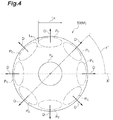
- FIG. 4 illustrates the eyeball 50 as viewed from the optical system 15.
- a pupil Pa indicates a state when the subject M is viewing the optical system 15.
- a pupil Pb indicates a state when the subject M views a side above the optical system 15.
- Another pupil Pc indicates a state when the subject M is viewing a position different from the optical system 15.
- An arrow D indicates the line-of-sight direction.
- a minor axis direction of an ellipse indicating the shape of the pupil P changes according to the line-of-sight direction (an arrow D).
- the minor axis direction is indicated by a slope ⁇ ' of the line-of-sight direction (an arrow D) with respect to the horizontal axis X'.
- of the angle ⁇ and the slope ⁇ are obtained by obtaining the inverse cosine component (slope ⁇ S ) and the direction of the minor axis (slope ⁇ ').
- the inverse cosine component (slope ⁇ S ) is obtained from the shape of the pupil P included in the image. Accordingly, the line-of-sight vector PT indicated by the magnitude
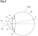
- FIG. 5 illustrates the optical axis AL and the visual axis AS in the eyeball 50.
- the optical axis AL is a symmetrical axis of the optical system of the eyeball 50.
- the visual axis AS is an axis on which the subject M actually views a visual target.
- the visual axis AS passes through a fovea centralis 57 in a retina 56.
- the visual axis AS is deviated by about 5 degrees from the optical axis AL.
- a result of the corneal reflection-pupil center method and the pupil shape method described above is the optical axis AL. Therefore, in the cornea reflection-pupil center method and the pupil shape method, it is assumed that the optical axis AL corresponds to the line of sight. There is a deviation between the visual axis AS and the optical axis AL.
- the visual axis AS is an axis passing through the position P S of the pupil center and the fovea centralis 57.
- the optical axis AL is a normal extending from the cornea 52 to a center of a crystalline lens 53. According to this deviation, when the subject M gazes at the optical system 15, the position G S of the corneal reflection does not match the position P S of the pupil center. Therefore, when the results obtained by the corneal reflection-pupil center method and the pupil shape method are calibrated, an output result of the line-of-sight detection device 1 approaches an actual line of sight.
- the optical axis AL of the eyeball 50 corresponds to the visual axis AS.
- a relationship shown in Equation (8) is established between the corneal reflection-pupil center vector r and the angle ⁇ formed by the camera-pupil center vector OP and the line-of-sight vector PQ.
- the vector r S corresponds to the visual axis AS obtained by removing the deviation (deviation vector ro) from the optical axis AL.
- the corneal reflection-pupil center vector r in Equation (6) is a vector r S indicating the visual axis AS, instead of assuming that the optical axis AL of the eyeball 50 is the visual axis AS (the line of sight).
- Equation (10) is obtained.
- the slope ⁇ S indicates that the slope ⁇ S is based on the assumption that the visual axis AS is the line of sight.
- the first coefficient k is a constant value.
- the first coefficient k is changed according to the magnitude
- Equation (10) a second term (-k
- the line-of-sight detection device 1 introduces a deviation angle ⁇ 0 .
- the deviation angle ⁇ 0 indicates a deviation of the optical axis AL with respect to the visual axis AS.
- Equation (11) is obtained as a new definition equation instead of Equation (10).
- ⁇ S k ⁇ r ⁇ ⁇ 0
- ⁇ S ⁇ ′ ⁇ ⁇ 0
- the slope ⁇ S corresponds to a vector indicating the visual axis AS.
- the deviation angle ⁇ 0 corresponds to a vector indicating a deviation of the optical axis AL with respect to the visual axis AS.
- the deviation angle ⁇ 0 is defined by the magnitude
- the line-of-sight detection device 1 includes a pair of cameras (the first camera and the second camera) 10 and the image processing device 20.
- the pair of cameras 10 are stereo cameras.
- the line-of-sight detection device 1 may further include the display device 30 that is a target that the subject M views.
- a purpose of use of the line-of-sight detection device 1 is not limited as already described. Therefore, an object at an end of the line of sight of the subject M is not limited to the display device 30.
- the object at the end of the line of sight of the subject M may be a windshield of a car.
- the display device 30 is not an indispensable element in the line-of-sight detection device 1.
- the camera 10 images the eyes of the subject M.
- the eye of the subject M includes the pupil P and the periphery of the pupil P.
- the camera 10 images the subject M in response to a command from the image processing device 20.
- the camera 10 outputs the image to the image processing device 20.
- Camera calibration is performed on the camera 10 in advance.
- a pair of cameras 10 are distinguished as a camera 10 L and a camera 10 R , as necessary.
- the camera 10 L is disposed on the left side of the subject M.
- the camera 10 R is disposed on the right side of the subject M.
- the pair of cameras 10 L and 10 R are connected to the image processing device 20 wirelessly or by wire. As a result, various pieces of data or commands are transmitted and received between the camera 10 and the image processing device 20.
- the pair of cameras 10 L and 10 R are disposed with a predetermined interval in a horizontal direction.
- the pair of cameras 10 L and 10 R are disposed at positions lower than a face of the subject M.
- An elevation angle of the camera 10 with respect to the horizontal axis is, for example, equal to or greater than 20 degrees and smaller than or equal to 35 degrees. According to this range, the pupil P can be reliably detected. Further, according to this range, it is possible to avoid interference with the field of view of the subject M.
- the camera 10 adopts an NTSC system, which is one of interlaced scanning systems. According to the NTSC system, 30 images can be obtained per second.
- the image includes an odd field including odd horizontal pixel lines and an even field including even horizontal pixel lines.
- the image is generated by the image of the odd field and the image of the even field being alternately captured at intervals of 1/60 second. Therefore, one frame corresponds to a pair of odd field and even field.
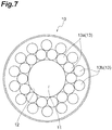
- the camera 10 includes an objective lens 11 and a light source 13.
- the objective lens 11 is accommodated in a circular opening 12.
- the light source 13 is provided outside the opening 12.
- the light source 13 irradiates the eye of the subject M with illumination light.
- the light source 13 includes a plurality of light emitting elements 13a and a plurality of light emitting elements 13b.
- the light emitting elements 13a are semiconductor light emitting elements (LEDs) that emit output light having a center wavelength of 850 nm.
- the light emitting elements 13a are disposed in a ring shape at regular intervals along an edge of the opening 12.
- the light emitting elements 13b are semiconductor light emitting elements that emit output light having a center wavelength of 940 nm.
- the light emitting elements 13b are disposed in a ring shape at regular intervals outside the light emitting elements 13a.
- the light emitting elements 13a and 13b emit illumination light along the optical axis of the camera 10. It should be noted that the arrangement of the light source 13 is not limited to the configuration illustrated in FIG. 7 , and other arrangements may be adopted as long as the camera 10 can be regarded as a pinhole model.
- the light source 13 emits illumination light according to a timing according to a command from the image processing device 20.
- the image processing device 20 controls operations of the camera 10 and the light source 13. Further, the image processing device 20 executes a process of detecting the line-of-sight direction of the subject M.
- the image processing device 20 may be constituted by a stationary or portable personal computer. Further, the image processing device 20 may be constituted by a workstation. Further, the image processing device 20 may be constituted by another type of computer. Alternatively, the image processing device 20 may be constituted by combining a plurality of any types of computers. When a plurality of computers are used, these computers are connected to one another via a communication network such as the Internet or an intranet.
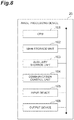
- FIG. 8 illustrates a general hardware configuration of the image processing device 20.
- the image processing device 20 includes a CPU (a processor) 101, a main storage unit 102, an auxiliary storage unit 103, a communication control unit 104, an input device 105, and an output device 106.
- the CPU 101 executes an operating system, an application program, and the like.
- the main storage unit 102 includes a ROM and a RAM.
- the auxiliary storage unit 103 includes a hard disk, a flash memory, and the like.
- the communication control unit 104 is constituted by a network card or a wireless communication module.
- the input device 105 includes a keyboard, a mouse, and the like.
- the output device 106 includes a display, a printer, and the like.
- the CPU 101 or the main storage unit 102 reads predetermined software.
- the CPU 101 operates the communication control unit 104, the input device 105, the output device 106, and the like.
- the main storage unit 102 or the auxiliary storage unit 103 reads and writes data. It should be noted that data or database necessary for processing is stored in the main storage unit 102 or the auxiliary storage unit 103.
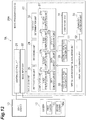
- the image processing device 20 includes a lighting control unit 21, an image input unit 22, and a calculation unit 23.
- the lighting control unit 21 controls a lighting timing of the light source 13.
- the image input unit 22 controls an imaging timing of the camera 10 in synchronization with a lighting timing of the light source 13.
- the image processing device 20 obtains an image (data of a plurality of eye images) from the camera 10.
- the calculation unit 23 detects the line of sight of the subject M by using the image input from the image input unit 22.
- the calculation unit 23 includes, as functional components, a recording unit 24, a preprocessing unit 26, a computation unit 27, a first optical axis acquisition unit 28, a second optical axis acquisition unit 29, an optical axis information acquisition unit 31, a visual axis acquisition unit 32, a calibration information unit 33, and a coefficient unit 34.
- the recording unit 24 has various types of information to be used for a line-of-sight detection process.
- the recording unit 24 can refer to from the preprocessing unit 26 and the computation unit 27.
- the recording unit 24 has, for example, information that is acquired in advance, such as internal parameters regarding the camera 10 or the position O S of the camera.
- the preprocessing unit 26 receives information from the image input unit 22 and the recording unit 24.
- the preprocessing unit 26 outputs a result to the computation unit 27.
- the preprocessing unit 26 receives an image from the image input unit 22.
- the preprocessing unit 26 obtains a dark pupil image and a bright pupil image from such an image.
- the preprocessing unit 26 receives information on the camera 10 from the recording unit 24. Using such information, the preprocessing unit 26 obtains the position P S of the pupil center, the position G S of the cornea reflection, the long axis of the pupil P, and the minor axis of the pupil P.
- the preprocessing unit 26 outputs information including the position P S of the pupil center, the position G S of the cornea reflection, the long axis of the pupil P, and the minor axis of the pupil P to the computation unit 27.
- the computation unit 27 receives information from the preprocessing unit 26 and the recording unit 24.
- the computation unit 27 outputs a result to the optical axis information acquisition unit 31, the first optical axis acquisition unit 28, and the second optical axis acquisition unit 29.
- the computation unit 27 receives information including the position P S of the pupil center, the position G S of the corneal reflection, the long diameter L A of the pupil P, and the minor diameter L B of the pupil P from the preprocessing unit 26.
- the computation unit 27 receives information on the camera 10 from the recording unit 24. Using these pieces of information, the computation unit 27 obtains various types of information to be used for the line-of-sight detection process.
- the computation unit 27 includes a first computation unit 27a, a second computation unit 27b, a third computation unit 27c, a fourth computation unit 27d, a fifth computation unit 27e, and a sixth computation unit 27f.
- the first computation unit 27a obtains the camera-pupil center vector OP (a first vector).
- the camera-pupil center vector OP is directed from the position O S of the camera to the position P S of the pupil center.
- the second computation unit 27b obtains the corneal reflection-pupil center vector r (a second vector).
- the corneal reflection-pupil center vector r is directed from the position G S of the corneal reflection to the position P S of the pupil center.
- the third computation unit 27c obtains the virtual viewpoint plane VS.
- the virtual viewpoint plane VS is a virtual plane having the camera-pupil center vector OP as a normal.
- the fourth computation unit 27d approximates an outer shape of the pupil P as an ellipse.
- the fourth computation unit 27d obtains the ellipticity R.
- the ellipticity R is a ratio of a major diameter to a minor axis of the ellipse.
- the fifth computation unit 27e obtains a gradient ⁇ ' between the minor axis of the ellipse indicating the pupil and the horizontal axis.
- the sixth computation unit 27f obtains information on the first virtual optical axis plane using the first eye image. Information on the first virtual optical axis plane is based on a third vector directed from the position G S of the first corneal reflection to the position P S of the first pupil center and a fourth vector directed from the first camera position to the position P S of the first pupil center.
- the information on the first virtual optical axis plane includes a first camera position, the position P S of the first pupil center, and a position at which a first optical axis AL1 intersects a first virtual viewpoint plane having the fourth vector as a normal.
- the seventh computation unit 27g obtains information on the second virtual optical axis plane using the second eye image.
- Information on the second virtual optical axis plane is based on a fifth vector directed from the position G S of the second corneal reflection to the position P S of the second pupil center and a sixth vector directed from the second camera position to the position P S of the second pupil center.
- the information on the second virtual optical axis plane includes the second camera position, the position P S of the second pupil center, and a position at which a second optical axis AL2 intersects the second virtual optical axis plane having the sixth vector as a normal.
- the first optical axis acquisition unit 28 obtains the optical axis AL through a process based on the cornea reflection-pupil center method.
- the first optical axis acquisition unit 28 receives information from the computation unit 27.
- the first optical axis acquisition unit 28 outputs a result to the optical axis information acquisition unit 31.
- the first optical axis acquisition unit 28 obtains the optical axis AL using the position P S of the pupil center obtained from the image and the position G S of the cornea reflection. More specifically, the first optical axis acquisition unit 28 obtains the optical axis AL using the magnitude
- the optical axis AL is indicated by an angle ⁇ (first angle) with reference to the camera-pupil center vector OP and a slope ⁇ (the second angle) with reference to the horizontal axis X' included in the virtual viewpoint plane VS.
- of the corneal Reflection-the pupil center vector r (the second vector) is associated with the angle ⁇ .
- the corneal reflection-pupil center vector r is associated with the slope ⁇ .
- the second optical axis acquisition unit 29 obtains the optical axis AL through a process based on the pupil shape method.
- the second optical axis acquisition unit 29 receives information from the computation unit 27.
- the second optical axis acquisition unit 29 outputs a processing result to the optical axis information acquisition unit 31.
- the second optical axis acquisition unit 29 obtains the ellipticity R and the slope ⁇ ' (a fourth angle).
- the slope ⁇ ' is a slope between the minor axis and the horizontal axis X'.
- the second optical axis acquisition unit 29 obtains the optical axis AL using the ellipticity R associated with the angle ⁇ and the slope ⁇ ' associated with the slope ⁇ .
- the optical axis information acquisition unit 31 receives information from the computation unit 27, the first optical axis acquisition unit 28, and the second optical axis acquisition unit 29.
- the optical axis information acquisition unit 31 outputs the result to the visual axis acquisition unit 32.
- the optical axis information acquisition unit 31 generates information for obtaining the optical axis AL using at least one of the first optical axis candidate and the second optical axis candidate on the basis of the pupil shape.
- the information for obtaining the optical axis AL is information for selecting one of the first optical axis candidate and the second optical axis candidate as the optical axis AL.
- the optical axis information acquisition unit 31 selects any one of the first optical axis candidate and the second optical axis candidate using the shape of the pupil P obtained from the image.
- the optical axis information acquisition unit 31 outputs the selected optical axis candidate to the visual axis acquisition unit 32.
- optical axis candidates are obtained in the first optical axis acquisition unit 28 and the second optical axis acquisition unit 29.
- an appropriate candidate is selected as a final result according to a slope of the visual axis.
- the optical axis information acquisition unit 31 selects the first optical axis candidate when the angle ⁇ with respect to the camera-pupil center vector OP is equal to or smaller than 30 degrees.
- the optical axis information acquisition unit 31 selects the second optical axis candidate when the angle ⁇ with respect to the camera-pupil center vector OP is greater than 30 degrees.
- the threshold value of the angle ⁇ may be set to a desired value.
- the visual axis acquisition unit 32 receives information from the first optical axis acquisition unit 28 or the second optical axis acquisition unit 29.
- the visual axis acquisition unit 32 also receives information from the calibration information unit 33.
- the visual axis acquisition unit 32 calibrates the optical axis AL input from the first optical axis acquisition unit 28 or the second optical axis acquisition unit 29 using the calibration information. As a result, the visual axis acquisition unit 32 obtains the visual axis AS.
- the calibration information unit 33 provides calibration information to the visual axis acquisition unit 32.
- the calibration information is the deviation angle ⁇ 0 described above.
- the calibration information may be obtained in advance and recorded in the calibration information unit 33.
- the calibration information may be calculated in the calibration information unit 33.
- the calibration information unit 33 obtains the calibration information, the calibration information unit 33 is connected to the computation unit 27, the first optical axis acquisition unit 28, the second optical axis acquisition unit 29, and the like.
- the calibration information unit 33 obtains the calibration information using the information input from such functional elements.
- the coefficient unit 34 provides the first coefficient k to the first optical axis acquisition unit 28. This first coefficient k may be acquired in advance and recorded in the coefficient unit 34. Further, the first coefficient k may be calculated in the coefficient unit 34.
- the coefficient unit 34 obtains the first coefficient k
- the coefficient unit 34 is connected to the computation unit 27, the first optical axis acquisition unit 28, the second optical axis acquisition unit 29, and the like. The coefficient unit 34 obtains the first coefficient k using the information input from these functional components.
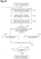
- the lighting control unit 21 controls a lighting timing of the light source 13.
- the image input unit 22 acquires a bright pupil image (an eye image) and a dark pupil image (an eye image) from the respective cameras 10 in synchronization with the lighting timing (step S11).
- the first optical axis acquisition unit 28 obtains the first optical axis candidate (step S12).
- the second optical axis acquisition unit 29 obtains the second optical axis candidate (step S13).
- the optical axis information acquisition unit 31 determines which of results of the corneal reflection-pupil center method and the pupil shape method as the line-of-sight detection processes is selected as an output using the shape of the pupil P (steps S14, S15, and S16).
- the visual axis acquisition unit 32 calibrate the optical axis candidate using the calibration information (step S17).
- the visual axis AS is obtained as a line of sight by executing steps S11, S12, S13, S14, S15, S16, and S17.
- the calculation unit 23 determines whether or not the process of obtaining the line of sight ends (step S18).
- step S18 the image processing device 20 ends the line-of-sight detection process (step S18: YES).
- the image processing device 20 executes the respective steps sequentially from step S11 again. The above process is repeatedly executed until an instruction to end the line-of-sight detection process is received.
- the light incident on the eye is diffusely reflected by the retina.
- the light passing through the pupil P has a property of returning to the light source with strong directivity.
- a part of the light reflected by the retina is incident on the opening 12 of the camera 10. Therefore, according to the optical system 15, it is possible to obtain the bright pupil image.
- the pupil P appears brighter than the periphery of the pupil P.
- the optical system 15 it is possible to obtain the dark pupil image.
- the pupil P appears dark.
- the eye is irradiated with light having a wavelength with high transmittance, reflection of the light on the retina is increased. Therefore, the pupil P appears bright.
- the eye is irradiated with light having a wavelength with low transmittance, the reflection of the light on the retina is decreased. Therefore, the pupil P appears dark.
- the light emitting element 13a emits light having a wavelength with a high transmittance (a center wavelength is 850 nm).
- the light emitting element 13a is provided at a position adjacent to the opening 12.
- the light emitting element 13b emits light having a wavelength with a low transmittance of the eye (a center wavelength is 940 nm).
- the light emitting element 13b is provided at a position away from the opening 12.
- the lighting control unit 21 and the image input unit 22 light the light emitting element 13a according to the odd field of the camera 10.
- the lighting control unit 21 and the image input unit 22 light the light emitting element 13b according to the even field of the camera 10.
- the image input unit 22 slightly shifts the operation timing of the camera 10 L with respect to the operation timing of the camera 10 R .
- An exposure time of the camera 10 is set to be equal to or shorter than a shift time.
- the lighting control unit 21 causes the corresponding light emitting element 13a and light emitting element 13b to emit light alternately. According to this control, it is possible to suppress an influence of the light from the light source 13 of one camera 10 on the image of the other camera 10. In other words, according to this control, occurrence of crosstalk can be suppressed.
- the image input unit 22 receives the bright pupil image and the dark pupil image obtained through the series of these controls from the camera 10.
- the input image has valid pixels only in the odd field or the even field. Therefore, the image input unit 22 embeds a luminance average of the pixel lines of the adjacent valid pixels into a pixel value between the lines. As a result, the image input unit 22 obtains the bright pupil image or the dark pupil image.
- the image input unit 22 outputs the bright pupil image and the dark pupil image obtained by the camera 10 to the calculation unit 23.
- the preprocessing unit 26 obtains corneal reflection G from each of the bright pupil image and the dark pupil image input from the image input unit 22. Specifically, the preprocessing unit 26 binarizes and labels one image using a P tiling method. The preprocessing unit 26 obtains a plurality of corneal reflections G from the image using information on the shape, and luminance average, or the like. Through such a process, the preprocessing unit 26 obtains the corneal reflection G from each of the bright pupil image and the dark pupil image. Subsequently, the preprocessing unit 26 obtains a position G S of the corneal reflection in the bright pupil image and the dark pupil image using the corneal reflection G obtained from the bright pupil image and the dark pupil image.
- the preprocessing unit 26 obtains the amount of position calibration.
- the amount of position calibration is the amount of movement of the corneal reflection between the bright pupil image and the dark pupil image.
- the amount of position calibration is based on an estimated or calculated position G S of the corneal reflection.
- the preprocessing unit 26 obtains a difference image. Specifically, the preprocessing unit 26 shifts an image of a previous field (an i-th field) to an image of a next field (a (i+1)-th field) by the amount of position calibration so that the positions G S of the two corneal reflections match each other. Then, the preprocessing unit 26 obtains a difference image from the two images.
- the preprocessing unit 26 obtains coordinates indicating the matched position G S of the corneal reflection, that is, the position G S of the cornea reflection based on the image coordinates.
- the preprocessing unit 26 obtains the difference image using the bright pupil image and the dark pupil image.
- alignment between the bright pupil image and the dark pupil image may be performed using the amount of position calibration described above. Since this differential image includes an emphasized pupil P, the differential image is also called a pupil image.
- the preprocessing unit 26 specifies the position P S of the pupil center from the difference image.
- the difference image does not change greatly in luminance from the previous frame. Therefore, the preprocessing unit 26 binarizes the difference image with a value of half of the average luminance as a threshold value, using the luminance average of the pupil P detected in the previous frame.
- the preprocessing unit 26 performs labeling on the binarized difference image.
- the preprocessing unit 26 obtains the pupil P from the connected components of the labeled pixels using shape parameters such as the area, size, area ratio, degree of square, and pupil feature quantity of the pupil P.
- the preprocessing unit 26 obtains the position (coordinates) of the pupil center in the difference image.
- the preprocessing unit 26 obtains three-dimensional coordinates of the pupil center. Specifically, the preprocessing unit 26 prepares two pupil images respectively obtained by the two cameras 10. Subsequently, the preprocessing unit 26 obtains the coordinates of the position P S of the pupil center in each of the two pupil images. Subsequently, the preprocessing unit 26 obtains three-dimensional coordinates of the position P S of the pupil center using a stereo method, by using the position P S of the pupil center.
- a position of a point in a space is determined for the coordinates of the point in the image.
- an object is imaged by using a plurality of cameras disposed at different positions.
- the position in the space is determined by using internal parameters and external parameters of the camera.
- the internal parameters include a focal length of a lens of the camera, an image center, a pixel size, and the like.
- the external parameters include a position or attitude of the camera.
- the preprocessing unit 26 obtains a relational equation between the coordinates of the position P S of the pupil center in the image coordinate system and the coordinates of the position P S of the pupil center in the world coordinate system in the three-dimensional space while referring to calibration data. Subsequently, the preprocessing unit 26 obtains three-dimensional coordinates of the position P S of the pupil center in the world coordinate system using a relational equation.
- the preprocessing unit 26 extracts an outer edge portion of a region indicating the pupil P in the difference image.
- a process of extracting the outer edge portion is not particularly limited.
- the preprocessing unit 26 obtains an approximate equation for approximating the extracted shape as an ellipse.
- the preprocessing unit 26 obtains information on the major diameter L A and the minor diameter L B when the pupil P is regarded as an ellipse using the approximate equation.
- the computation unit 27 obtains information that is used for a first line-of-sight detection process, a second line-of-sight detection process, and the visual axis calculation process.
- the second computation unit 27b sets a virtual viewpoint plane VS'-Y' using the three-dimensional position of the position P S of the pupil center.
- the virtual viewpoint plane VS'-Y' is a plane having the camera-pupil center vector OP as a normal.
- the camera-pupil center vector OP is a vector connecting an origin O to the position P S of the pupil center, with a center of the opening 12 of the camera 10 as the origin O.
- the virtual viewpoint plane VS'-Y' corresponds to the projection plane (an image plane) of the image captured by the camera 10.
- an X' axis corresponds to an intersection line between an XW-ZW plane of a world coordinate system and the virtual viewpoint plane VS'-Y'.
- the second computation unit 27b obtains a vector r G from the corneal reflection G on the image surface S G to the position P S of the pupil center.
- the second computation unit 27b converts the vector r G into the corneal reflection-pupil center vector r.
- the corneal reflection-pupil center vector r is a vector obtained by converting the vector r G to an actual magnitude using a magnification factor of the camera.
- the magnification factor of the camera is obtained from a distance of the camera-pupil center vector OP.
- each camera 10 is considered to be a pinhole model, and the position G S of the corneal reflection and the position P S of the pupil center are assumed to be on a plane parallel to the virtual viewpoint plane VS'-Y'.
- the second computation unit 27b obtains the corneal reflection-pupil center vector r.
- the corneal reflection-pupil center vector r indicates relative coordinates of the position P S of the pupil center and the position G S of the corneal reflection.
- the relative coordinates are the coordinates on the plane parallel to the virtual viewpoint plane VS'-Y' and including the three-dimensional coordinates of the position P S of the pupil center.
- the corneal reflection-pupil center vector r indicates an actual distance from the position G S of the corneal reflection to the position P S of the pupil center.
- the first line-of-sight detection process is executed in the first optical axis acquisition unit 28.
- the first optical axis acquisition unit 28 obtains the first optical axis candidate using the cornea reflection-pupil center method.
- the first optical axis acquisition unit 28 obtains an angle ⁇ corresponding to the optical axis AL shown in Equation (12).
- ⁇ k ⁇ r
- the corneal reflection-pupil center vector r is known since the corneal reflection-pupil center vector r is obtained by the second computation unit 27b.
- a slope ⁇ which is a component of the angle ⁇ is an angle formed by the corneal reflection-pupil center vector r and the horizontal axis X'. Therefore, the slope ⁇ is known. Then, the angle ⁇ is obtained by obtaining the magnitude
- of the angle ⁇ is obtained by calculating an absolute value of the corneal reflection-pupil center vector r and multiplying the absolute value by a first coefficient k.
- of the angle ⁇ and the slope ⁇ of the angle ⁇ are obtained.
- the angle ⁇ as the first optical axis candidate is obtained.
- a second line-of-sight detection process is executed in the second optical axis acquisition unit 29.
- the second optical axis acquisition unit 29 obtains the second optical axis candidate by using the pupil shape method.
- an angle ⁇ corresponding to the optical axis AL is obtained.
- which is a component of the angle ⁇ corresponds to a slope ⁇ S (see FIG. 3(b) ).
- the slope ⁇ which is a component of the angle ⁇ corresponds to the slope ⁇ ' (see FIG. 4 ).
- the second optical axis acquisition unit 29 obtains a slope ⁇ ' using a direction of the minor axis.
- of the angle ⁇ and the slope ⁇ ' corresponding to the slope ⁇ of the angle ⁇ are obtained.
- the angle ⁇ as the second optical axis candidate is obtained.
- the optical axis information acquisition unit 31 selects any one of a process based on the corneal reflection-pupil center method and a process based on the pupil shape method as the line-of-sight detection process. This selection is based on the magnitude
- the optical axis information acquisition unit 31 selects the pupil shape method when the magnitude
- the corneal reflection-pupil center method when the magnitude
- the image processing device 20 sets a threshold value.
- This threshold value is used to distinguish between a range in which linearity is dominant in the relationship between the corneal reflection-pupil center vector r and the angle ⁇ (a range in which the corneal reflection G appears in most of the subjects M) and a range in which non-linearity is dominant in the relationship between the corneal reflection-pupil center vector r and the angle ⁇ .
- of the angle ⁇ about 30 degrees is exemplified as the threshold value.
- the threshold value is not limited to 30 degrees, and a desired value may be used.
- the image processing device 20 obtains the magnitude
- the image processing device 20 obtains a slope ⁇ S corresponding to the magnitude
- the optical axis information acquisition unit 31 selects a result of the corneal reflection-pupil center method and outputs the first optical axis candidate to the visual axis acquisition unit 32.
- the optical axis information acquisition unit 31 selects a result of the pupil shape method and outputs the second optical axis candidate to the visual axis acquisition unit 32.
- a process of acquiring the visual axis is executed in the visual axis acquisition unit 32.
- the process of acquiring the visual axis is a process of calibrating a deviation of the optical axis AL from the visual axis AS.
- the visual axis acquisition unit 32 performs a process shown in Equation (15). That is, the visual axis acquisition unit 32 executes a vector calculation for subtracting the deviation angle ⁇ 0 from the angle ⁇ AL1 as the optical axis AL.
- the slope ⁇ S is the visual axis AS.
- the visual axis acquisition unit 32 When the second optical axis candidate is output as the optical axis AL to the visual axis acquisition unit 32, the visual axis acquisition unit 32 performs the process shown in Equation (16). That is, the visual axis acquisition unit 32 executes a vector calculation for subtracting the deviation angle ⁇ 0 from the angle ⁇ AL2 as the optical axis AL.
- the slope ⁇ S is the visual axis AS.
- the line-of-sight detection device 1 includes a first optical axis acquisition unit 28 and a second optical axis acquisition unit 29.
- the first optical axis acquisition unit 28 obtains the optical axis AL using the position P S of the pupil center and the position G S of the corneal reflection. Therefore, the line-of-sight detection device 1 can perform line-of-sight detection in a range of the line of sight in which the corneal reflection G is obtained.
- the second optical axis acquisition unit 29 obtains the optical axis AL using the shape of the pupil P. Therefore, the line-of-sight detection device 1 can perform line-of-sight detection even in a range of the line of sight in which the corneal reflection G cannot be obtained.
- the optical axis information acquisition unit 31 obtains information for selecting any one of the first optical axis acquisition unit 28 and the second optical axis acquisition unit 29 using the shape of the pupil P.
- the visual axis acquisition unit 32 a deviation between the optical axis AL and the visual axis AS of the selected optical axis candidate is calibrated, and the visual axis AS as a line of sight is obtained. Therefore, the line-of-sight detection device 1 can extend the range in which the line of sight can be satisfactorily detected, from a narrow line-of-sight range in which the corneal reflection G can be obtained to a wide line-of-sight range in which the corneal reflection G cannot be obtained.
- the line-of-sight detection device 1 it is possible to execute the corneal reflection-pupil center method and the pupil shape method on the same platform (a foundation or a basic theory).
- the line of sight (or a gazing point) is detected by using the relative position between the position G S of the corneal reflection and the position P S of the pupil center obtained from the image.
- the line of sight (or the gazing point) is detected by using the shape of the pupil P defined by the ellipticity R and the direction of the minor axis.
- the corneal reflection-pupil center method three-dimensional coordinates of the pupil P is obtained using the optical system 15 in which the camera 10 is calibrated.
- the corneal reflection-pupil center method obtains the angle ⁇ between the camera-pupil center vector OP and the optical axis AL of the eyeball 50. These are obtained using the corneal reflection-pupil center vector OP and the corneal reflection-pupil center vector r obtained from the image.
- the pupil shape method first, three-dimensional coordinates of the pupil P are obtained. Then, in the pupil shape method, the camera-pupil center vector OP is obtained. Then, the angle ⁇ is obtained.
- the angle ⁇ is obtained using the ellipticity R of the ellipse indicating the outer shape of the pupil P and the direction of the minor axis. Therefore, according to the line-of-sight detection device 1, the corneal reflection-pupil center method and the pupil shape method can be executed on the same platform.
- the line-of-sight detection device 1 causes the subject M to gaze at a visual target for calibration of which coordinates are known in the cornea reflection-pupil center method.
- the line-of-sight detection device 1 obtains the deviation between the visual axis AS (the direction vector of the visual axis AS) and the optical axis AL (the direction vector of the optical axis) as the deviation angle ⁇ 0 .
- a process of obtaining this deviation is called user calibration or gazing point calibration.
- the line-of-sight detection process or the gazing point detection process
- an output result acquired as the optical axis AL is calibrated using the deviation angle ⁇ 0 .
- the pupil shape method it is possible to use the deviation angle ⁇ 0 clarified by user calibration for calibration of the output result acquired as the optical axis AL.
- the line-of-sight detection device 1 performs calibration of the deviation between the visual axis AS and the optical axis AL at a rear stage in the process of obtaining the line of sight.
- the line-of-sight detection device 1 performs a calibration process after the process of obtaining the optical axis AL. According to this configuration, even when processes of obtaining the optical axis AL are different processes, a result obtained from these processes is the optical axis AL. Therefore, it is possible to easily execute the calibration process.
- the calibration process may be a process of calibrating by viewing one point (a one-point calibration method) or may be another process. Then, for example, when the visual target presented at the center of the screen is viewed for a moment, the corneal reflection-pupil center method is executed. As a result, calibration information (deviation angle ⁇ 0 ) is obtained. In a case in which the subject M views a position greatly far away from the optical system 15, the calibration information (the deviation angle ⁇ 0 ) can also be used even when the pupil shape method is applied. Therefore, a burden on the subject M with respect to the calibration can be reduced. Further, the line-of-sight detection in a wide angle range becomes possible as compared with a case in which only the corneal reflection-pupil center method is used.
- a range in which predetermined line-of-sight detection accuracy in the line-of-sight detection device 1 can be obtained is ⁇ 45 degrees in the horizontal direction with reference to the corneal reflection-pupil center vector OP. This range was confirmed by actually performing experiments. Further, it is assumed that the size
- of the angle ⁇ 60 degrees as a detection range. In this case, the ellipticity R (the ratio of the minor diameter to the major diameter) is 0.5. Therefore, by improving the image processing and controlling the light source, at least about
- 60 degrees can be measured. It should be noted that examples of a remote line-of-sight detection device or gazing point detection device of which the detection range is 45 degrees or more have not been reported.
- Equation (17) the first coefficient k is included in Equation (17) of the corneal reflection-pupil center method.
- the first coefficient k may be treated as a constant value. Further, the first coefficient k may be treated as a changing value. For example, when the angle ⁇ is small, a relationship between the angle ⁇ and the corneal reflection-pupil center vector r has a high linearity in Equation (17). Therefore, the first coefficient k is treated as a constant value. On the other hand, when the angle ⁇ is large, the relationship between the angle ⁇ and the corneal reflection-pupil center vector r is has storing nonlinearity in Equation (17). Therefore, the first coefficient k is treated as a value that changes according to the corneal reflection-pupil center vector r. Further, the first coefficient k changes according to personality of the eyeball 50 of the subject M.
- Equation (18) is obtained for each of the cameras 10.
- the camera 10 L is disposed at a position (O S1 )
- the camera 10 R is disposed at a position (O S2 ).
- the corneal reflection G occurring in the left eye (first eye) is a position (G S1 )
- the corneal reflection G occurring in the right eye (second eye) is a position (G S2 ).
- a pupil center position of the left eye is a position (P S1 ).
- a pupil center position of the right eye is a position (P S2 ).
- An angle ⁇ 1 indicates the visual axis AS obtained from the camera 10 L .
- An angle ⁇ 1 ' indicates the optical axis AL obtained from the camera 10 L .
- the angle ⁇ 0 indicates the deviation angle.
- a corneal reflection-pupil center vector r 1 (a third vector) indicates a vector obtained from the camera 10 L .
- An angle ⁇ 2 indicates the visual axis AS obtained from the camera 10 R .
- the angle ⁇ 2 ' indicates the optical axis AL obtained from the camera 10 R .
- a corneal reflection-pupil center vector r 2 (a fifth vector) indicates a vector that is obtained from the camera 10 R .
- Equation (18) since the first coefficient k and the deviation angle ⁇ 0 are unique to the eyeball, the first coefficient k and the deviation angle ⁇ 0 are common. [Math.
- Equation (19) is obtained from Equation (18).
- Equation (20) the first coefficient k is a positive real number. Therefore, Equation (19) is shown as Equation (20).
- Equation (20) it is possible to obtain the first coefficient k as a constant value by using Equation (20). It should be noted that according to Equation (20), even when the subject M views any visual target, the first coefficient k can be obtained for each frame.
- Equation (21) is shown as Equation (22).
- Equation (22) the slope ⁇ ' of the corneal reflection-pupil center vector r and the slope ⁇ of the angle ⁇ match each other. In other words, Equation (23) is obtained. [Math. 23]
- the slope ⁇ ' of the corneal reflection-pupil center vector r is obtained using the image obtained by the camera 10 and the internal parameters of the camera.
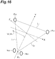
- two virtual optical axis planes VL 1 and VL 2 are shown for the two optical systems 15.
- the intersection line CL of the virtual optical axis planes VL 1 and VL 2 corresponds to the optical axis AL.
- the virtual optical axis plane VL 1 includes a position (O S1 ) of the first camera, a position (P S1 ) of the pupil center, and a position at which the first optical axis intersects the first virtual viewpoint plane.
- the first virtual viewpoint plane is a plane having a fourth vector directed from the first camera position (O S1 ) to the position (P S1 ) of the pupil center as a normal.
- the virtual optical axis plane VL 2 includes the position (O S2 ) of the second camera, the position (P S2 ) of the pupil center, and a position at which the second optical axis intersects the second virtual viewpoint plane.
- the second virtual viewpoint plane is a plane having a sixth vector directed from the second camera position (O S2 ) to the position (P S2 ) of the pupil center as a normal.
- the optical axis AL can be obtained irrespective of the magnitude
- Obtaining the optical axis AL corresponds to obtaining the angle ⁇ with respect to the optical system 15. Therefore, a first coefficient (k 1 ) corresponding to the left eye is obtained by using the fifth angle ( ⁇ 1 ) and the magnitude (
- the fifth angle ( ⁇ 1 ) is obtained from the intersection line at which the first virtual optical axis plane and the second virtual optical axis plane intersect each other and the fourth vector. Further, a first coefficient (k 2 ) corresponding to the right eye is obtained using the fifth angle ( ⁇ 2 ) obtained from the intersection line and the sixth vector and the magnitude (
- the corneal reflection-pupil center vectors r 1 and r 2 are also obtained from the respective optical systems 15. Therefore, it is possible to determine the nonlinear function f shown in Equation (23) by plotting a relationship between the magnitude
- the angle ⁇ is obtained from the image acquired by the camera 10 using the corneal reflection-pupil center vector r. Therefore, the optical axis AL of the eyeball 50 can be obtained for each camera 10.
- the function f acquired in advance may be repeatedly used. Further, the function f may be updated each time data is increased.
- the angle ⁇ is obtained.
- the pupil P is obtained, it is possible to obtain the visual axis AS passing through the pupil P and the visual target position.
- the pupil shape method does not include a coefficient corresponding to the first coefficient k in the corneal reflection-pupil center method.
- the second coefficient h may be treated as a constant value, similar to the first coefficient k. Further, the second coefficient h may be treated as a changing value. The second coefficient h is obtained by the same method as the method for the first coefficient k.
- the pupil P observes an object through the lens called the cornea. Therefore, as the angle of the line of sight with respect to the camera 10 increases, a relationship between the ellipticity R and the angle ⁇ deviates due to refraction of light caused by the cornea. Therefore, nonlinear calibration is required in the relationship between the ellipticity R and the angle ⁇ .
- the virtual optical axis planes VL 1 and VL 2 are obtained from information on only a minor-axis direction of the ellipse of the pupil P. Therefore, the process of acquiring the first coefficient k is not affected by the refraction. That is, it is not necessary to take refraction into consideration in the process of acquiring the first coefficient k.
- the line-of-sight detection process is executed by repeating steps S11 to S18 described above.
- the calibration information indicating the deviation between the optical axis AL and the visual axis AS has been described as the deviation angle ⁇ 0 .
- This deviation angle ⁇ 0 is acquired in the calibration step that is performed before a repetitive process including steps S11 to S18.
- FIG. 12 illustrates a virtual plane with the intersection T 1 as an origin. This virtual plane is obtained by replacing the position of the camera of the virtual viewpoint plane in FIG. 12 with an intersection between the optical axis AL of the eyeball and the display.
- an intersection line between the virtual plane VP 1 and an XZ plane (a horizontal plane) of the world coordinate system is defined as a horizontal axis of the virtual plane VP 1 .
- An intersection of the virtual plane VP 1 and the visual axis AS is obtained.
- Conversion into a vector in a coordinate system of the virtual viewpoint plane is performed.
- calibration information (deviation angle ⁇ 0 ) indicating the deviation between the visual axis AS and the optical axis AL is obtained.
- the present invention has been described in detail based on the embodiment thereof. However, the present invention is not limited to the above embodiment. The present invention can be variously modified without departing from the gist thereof.
- the image processing device 20A of the line-of-sight detection device 1 may include a direction determination unit 35.
- the direction determination unit 35 determines the direction of the visual axis AS with respect to the camera-pupil center vector OP.
- FIG. 14(a), (b), (c), and (d) illustrate a positional relationship between the pupil P of the subject M, a glow 55, and the corneal reflection G.
- FIG. 14(a) illustrates a positional relationship among the pupil P, the glow 55, and the corneal reflection G when the subject M views the visual target on the right side of the camera 10.
- FIG. 14(b) illustrates a positional relationship among the pupil P, the glow 55, and the corneal reflection G when the subject M is viewing the visual target at a position on the right side of the camera 10 and closer to the camera 10 relative to the visual target in FIG. 14(a).
- FIG. 14(a), (b), (c), and (d) illustrate a positional relationship between the pupil P of the subject M, a glow 55, and the corneal reflection G.
- FIG. 14(c) illustrates a positional relationship among the pupil P, the glow 55, and the corneal reflection G when the subject M views the camera 10 or the light source 13.
- FIG. 14(d) illustrates a positional relationship among the pupil P, the glow 55, and the corneal reflection G when the subject M views the visual target on the left side of the camera 10.
- FIG. 14(e) illustrates a positional relationship among the pupil P, the glow 55, and the corneal reflection G when the subject M is viewing the visual target at a position on the left side of the camera 10 and farther from the camera 10 relative to the visual target in FIG. 14(d) .
- the reflection image (the corneal reflection G) of the light emitted from the light source 13 is generated outside the cornea. That is, the reflected image of the light emitted from the light source 13 is generated in a white eye region.
- a reflection image of the light emitted from the light source 13 is generated at a position away from the pupil P on the cornea.
- a reflection image of the light emitted from the light source 13 is generated at a position close to the pupil P on the cornea.
- the reflection image generated in the white eye region is not stabilized due to nonuniformity of the shape of the white eye or the like. Therefore, the reflection image generated in the white eye region is not suitable for use in high-precision eye-line-of-sight detection.
- a method of determining whether the subject views the right or views the left according to whether the reflection image generated in the white eye region exists on the left or right side of the pupil P is known.
- the characteristics of the image greatly changes according to the eyeglasses, the subject M, and an angle of the head of the subject M.
- the white eye reflection also changes.
- the shape of the pupil P in the image is the same either when the subject views a left index or when the subject views a right index.
- the ellipticity R indicating the shape of the pupil P is the same either when the subject views a left index or when the subject views a right index as long as the angle of the visual axis AS with respect to the camera-pupil center vector OP is the same. That is, in the method of using the ellipticity R of the pupil P, when the subject views indices at point-symmetric positions with the optical system 15 interposed therebetween (for example, upper right and lower left), both cases cannot be distinguished since the cases indicate the same value of the ellipticity R.
- the image processing device 20A may include the direction determination unit 35.
- the direction determination unit 35 discriminates the line-of-sight direction with respect to the camera-pupil center vector OP.
- FIG. 15(a) illustrates a case in which the subject M views the right side of the two optical systems 15 L and 15 R that are horizontally disposed. In this case, a slope ⁇ 1 is greater than a slope ⁇ 2 .
- the slope ⁇ 1 is a slope between the left optical system 15 L of the subject M and a line of sight AG 1 of the left eye.
- the slope ⁇ 2 is a slope between the right optical system 15 R and the line of sight AG 2 of the left eye.
- the ellipticity R 2 obtained from the image GRR of the right optical system 15 R is greater than the ellipticity R 1 obtained from the image GRL of the left optical system 15 L .
- the same may apply to the right eye.
- the ellipticity R 2 obtained from the image GRR of the right optical system 15 R is greater than the ellipticity R 1 obtained from the image GRL of the left optical system 15 L .
- rough distinguishment between the subject M viewing the right or viewing the left can be performed by comparing the ellipticity R 1 and R 2 of the pupil P included in the images GRL and GRR respectively acquired by the left and right optical systems 15 L and 15 R with each other.
- the line-of-sight detection device 1 is not limited to the configuration of the functional block diagram illustrated in FIG. 9 .
- the line-of-sight detection device 1 may appropriately change a relationship between the respective functional blocks for efficiency of the process and the like.
- the first optical axis acquisition unit 28 and the second optical axis acquisition unit 29 may include a first computation unit 27a, a second computation unit 27b, a third computation unit 27c, a fourth computation unit 27d, a fifth computation unit 27e, a sixth computation unit 27f, and a seventh computation unit 27g constituting the computation unit 27.
- the line-of-sight detection method is not limited to an order shown in the flowchart of FIG.
- the optical axis acquisition unit may be selected and the optical axis AL may be obtained only in the selected optical axis acquisition unit.
- the process of calibrating the optical axis may be executed immediately after the first optical axis candidate is obtained, and the process of calibrating the optical axis may be executed immediately after the second optical axis candidate is obtained. In this case, in the line-of-sight detection method, the calibration process is executed twice in the process of obtaining one visual axis AS.
- the second optical axis acquisition unit 29 of the line-of-sight detection device 1 obtains the optical axis using the pupil shape.
- the pupil P is covered by the cornea 52 (see FIG. 5 ).
- the camera 10 outputs an image of the pupil P via the cornea 52.
- refraction is likely to occur when the light passes through the cornea 52. Therefore, the position of the corneal contour on the image is likely to be deviated with respect to the position of the actual pupil contour. Therefore, the line-of-sight detection device 1 corrects the ellipticity R.
- a deviation of the position of the pupil contour on the image with respect to a position of the actual pupil contour is corrected.
- the line-of-sight detection device 1 obtains the corrected ellipticity R' obtaining by correcting the ellipticity R.
- the line-of-sight detection device 1 performs the line-of-sight detection process using the corrected ellipticity R'.
- the correction of the ellipticity R may be executed by the second optical axis acquisition unit 29.
- the correction of the ellipticity R may be executed by the fourth computation unit 27d that obtains the ellipticity R.
- Equation (25) is used for correction of the ellipticity R.
- R ′ a ⁇ R 2 + b ⁇ R
- R' is a corrected ellipticity.
- R is an ellipticity.
- the second optical axis acquisition unit 29 may obtain the slope ⁇ S by directly using the inverse cosine component of the reciprocal of the ellipticity R (see Equation (7)).
- the line-of-sight detection device 1 also executes a process based on the pupil shape method on a platform that performs a process based on the cornea reflection-pupil center method. That is, the line-of-sight detection device 1 according to the present embodiment executes a process based on the cornea reflection-pupil center method and a process based on the pupil shape method on one platform.
- the present invention is not limited to such a platform, and the process based on the corneal reflection-pupil center method and the process based on the pupil shape method may be executed on a platform that executes another process.
- the process based on the corneal reflection-pupil center method and the process based on the pupil shape method may be executed on a platform that obtains a face posture of the subject M.
- the "face posture” referred to herein means a position and a direction of a skull of the subject M.
- the face posture is not related to a direction (for example, line of sight) of the eyeball of the subject M.
- Patent Literature Japanese Unexamined Patent Publication No. 2007-26073
- the face posture of the subject M is indicated by a face posture vector V B .
- the face posture vector V B is obtained using the pupils and nostrils of the subject M.
- the face posture vector V B is a normal vector of a plane passing through three points of a position P S1 of the left pupil center, a position P S2 of the right pupil center, and a position P 0 of the center between the nostrils.
- the left pupil, the right pupil, the left nostril (first nostril) center, the right nostril (second nostril) center, and the center between the nostrils can be defined as feature points. Three-dimensional coordinates of these feature points can be obtained using several calculation schemes.
- the line-of-sight detection device 1B physically has the same configuration as the line-of-sight detection device 1 according to the embodiment.
- functional components in the image processing device 20B are different from those in the line-of-sight detection device 1.
- the line-of-sight detection device 1B includes a coordinate acquisition unit 26a and a face posture acquisition unit 36 as functional components for detecting a face posture.
- the coordinate acquisition unit 26a is included in the preprocessing unit 26B in the calculation unit 23B.
- the face posture acquisition unit 36 is included in the calculation unit 23B.
- the coordinate acquisition unit 26a is a component of the preprocessing unit 26.
- the coordinate acquisition unit 26a obtains three-dimensional coordinates regarding the positions (P S1 , P S2 ) of the pupil center. Further, the coordinate acquisition unit 26a obtains three-dimensional coordinates regarding the positions (P 0 , N S1 , N S2 ) of the nostrils. It should be noted that the coordinate acquisition unit 26a only has to be able to obtain the three-dimensional coordinates. Therefore, the coordinate acquisition unit 26a does not have to be a component of the preprocessing unit 26.
- the coordinate acquisition unit 26a uses the first image acquired by the first camera 10 L and the second image acquired by the second camera 10 R . Using the first image acquired by the first camera 10 L and the second image acquired by the second camera 10 R , the coordinate acquisition unit 26a obtains three-dimensional coordinates of the position (P S1 , P S2 ) of the pupil center and three-dimensional coordinates of the positions (P 0 , N S1 , N S2 ) of the nostrils using the stereo matching method.
- the coordinate acquisition unit 26a performs the following operation.
- three coordinate systems are used for a determination of the three-dimensional coordinates of the pupil center using the stereo method.
- the three coordinate systems are a world coordinate system C W (X W , Y W , Z W ), a camera coordinate system C C (X C , Y C , Z C ), and an image coordinate system C G (X G , Y G , Z G ).
- the world coordinate system C W defines any point to be shared among a plurality of cameras.
- the three-dimensional coordinates of the feature point are based on the world coordinate system C W .
- a relationship between the world coordinate system C W and the camera coordinate system C C is shown by Equation (28).
- a rotation matrix M R and a translation vector T R in Equation (28) are constants that are obtained through camera calibration.
- the face posture acquisition unit 36 obtains a face posture vector using the three-dimensional coordinates of the position (P S1 , PS2 ) of the pupil center and three-dimensional coordinates of the positions (N S1 , N S2 ) of the nostrils.
- the face posture acquisition unit 36 obtains three reference parts using four pieces of coordinate information (P S1 , P S2 , N S1 , N S2 ). A set of three reference parts is a reference part group. Then, the face posture acquisition unit 36 sets a virtual plane.
- the virtual plane is a triangular plane of which a vertex is a point indicated by the three generated reference parts.
- the face posture acquisition unit 36 obtains a face posture vector V B passing through a centroid of the virtual plane.
- the face posture vector V B is information indicating the face posture.
- the face posture acquisition unit 36 may select the position P S1 of the pupil center of the right eye, the position P S2 of the pupil center of the left eye, and the position P 0 of the center of the nostrils as the reference part group (see FIG. 16 ).
- the position P 0 of the center between the nostrils is an average of the position N S1 of the right nostril and the position N S2 of the left nostril.
- the face posture acquisition unit 36 selects the position P S1 of the pupil center of the right eye, the position P S2 of the pupil center of the left eye, and the position N S1 of the right nostril as the first reference part group.
- the face posture acquisition unit 36 obtains a first normal vector using these.
- the face posture acquisition unit 36 selects the position P S1 of the pupil center of the right eye, the position P S2 of the pupil center of the left eye, and the position N S2 of the left nostril as a second reference part group.
- the face posture acquisition unit 36 obtains a second normal vector using these. It should be noted that the face posture acquisition unit 36 may obtain an average of the first normal vector and the second normal vector as the face posture vector V B .
- the line-of-sight detection device 1B according to the modification example can extend the range in which the line of sight can be detected. Further, the line-of-sight detection device 1B can obtain a face posture of the subject M.
- the operation of the coordinate acquisition unit is not limited to the process based on the stereo matching method.
- any process may be selected as long as the process is a process capable of acquiring the three-dimensional coordinates of the pupil P and nostrils.
- the coordinate acquisition unit 26b may obtain three-dimensional coordinates through a process called a constraint condition method.
- the constraint condition method three-dimensional coordinates of feature points are obtained by using a distance between the feature points (hereinafter referred to as "inter-feature point distance" or simply a "distance”) as constraint conditions.
- the inter-feature point distance is, for example, a distance L 1 between the position P S1 of the left pupil center and the position P S2 of the right pupil center, a distance L 2 between the position P S1 of the left pupil center and the position P 0 of the center between the nostrils, and a distance L 3 between the position P S2 of the right pupil center and the position P 0 of the center between the nostrils (see FIG. 16 ).
- two optical systems for example, cameras
- three-dimensional coordinates can be obtained only with a third image acquired by one camera (a third camera). Therefore, according to the constraint condition method, it is possible to extend the detection range of the face direction in a separation direction of the optical system by disposing the two optical systems at a distance and using the respective optical systems.
- the line-of-sight detection device 1C physically has the same configuration as the line-of-sight detection device 1 according to the embodiment.
- the functional components in the image processing device 20C are different from the line-of-sight detection device 1.
- the line-of-sight detection device 1C has a coordinate acquisition unit 26b as a functional component for detecting the face posture.
- the coordinate acquisition unit 26b is included in the preprocessing unit 26C in the calculation unit 23C.
- the coordinate acquisition unit 26b includes a distance computation unit 26c, a two-dimensional coordinate computation unit 26d, and a three-dimensional coordinate computation unit 26e.
- the calculation unit 23C includes a face posture acquisition unit 36.
- the imaging optical system in the line-of-sight detection device 1C can be assumed to be a pinhole model with a focal length f (see FIG. 20 ).
- Two-dimensional coordinates of center points of the right pupil, the left pupil, the left nostril, and the right nostril on a nostril image (imaging plane PL) in the camera coordinate system C C are Q 1 , Q 2 , Q 3 , and Q 4 .
- the camera coordinate system C C is assumed to be a position origin O R of the pinhole.
- the preprocessing unit 26 obtains coordinates (inter-nostril center coordinates) P 0 of a midpoint of both nostrils (a center between the nostrils), the position P S1 of the right pupil center, and the position P S2 of the left pupil center.
- a distance of each side of a triangle connecting the three feature points is shown as a distance L ij between the points i and j (see Equation (29)) when any one of the points is i and the other points are j.
- This distance L ij is obtained through actual measurement that is performed in advance.
- the two-dimensional position on the imaging plane PL corresponding to each feature point is shown by using a position vector from the pinhole to each feature point and the focal length f of the camera (see Equation (29)).
- the process of obtaining the two-dimensional position on the imaging plane PL is executed by the two-dimensional coordinate computation unit 26d.
- Q n X n ⁇ f / Z n , Y n f / Z n
- a unit vector corresponding to the position vector directed from the pinhole to each feature point is shown by Equation (30).
- u ⁇ n x n , y n , f x n 2 + y n 2 + f 2
- Equation (33) is established.
- Equation (34) is obtained.
- the face posture acquisition unit 36 obtains a 0 , a 1 , and a 2 using a simultaneous Equation (Equation (34)).
- the face posture acquisition unit 36 applies a solution to the simultaneous equation to Equation (32).
- the face posture acquisition unit 36 obtains a position vector.
- the position vector indicates three-dimensional coordinates of each feature point.
- the process of obtaining the three-dimensional coordinates is executed by the three-dimensional coordinate computation unit 26e.
- the line-of-sight detection device 1C according to the modification example can extend the range in which the line of sight can be detected. Further, the line-of-sight detection device 1C can obtain a face posture of the subject M.
- the information generated by the optical axis information acquisition unit 31 is information for selecting one of the first optical axis candidate and the second optical axis candidate as the optical axis AL.
- the information generated by the optical axis information acquisition unit 31 may be information for generating the optical axis AL using both the first optical axis candidate and the second optical axis candidate (Equation (35)).
- Equation (35) a weighting factor w1 is set in the information (magnitude
- the information generated by the optical axis information acquisition unit 31 may be the information indicating Equation (35) and the weighting factors w1 and w2 in Equation (35).
- w 1 ⁇
- w 1 + w 2 1
- the weighting factors w1 and w2 can have values between 0 and 1 with the slope ⁇ S as a variable.
- a threshold value ⁇ T for example, 30 degrees
- a predetermined numerical range including the threshold value ⁇ T is set.
- the weighting factor w1 is set to 1 and the weighting factor w2 is set to 0.
- the weighting factor w1 is set to 0 and the weighting factor w2 is set to 1.
- the first optical axis candidate is set as the optical axis AL.
- the second optical axis candidate is set as the optical axis AL.
- the optical axis AL may be obtained using the weighting factor w1 and the weighting factor w2.
- the weighting factor w1 may be set to 0.5 and the weighting factor w2 may be set to 0.5.
- a relationship between the weighting factors w1 and w2 and the slope ⁇ S may be changed stepwise.
- the first optical axis candidate is used for acquisition of the optical axis AL.
- the second optical axis candidate is used for acquisition of the optical axis AL. That is, this is the same as the operation of the optical axis information acquisition unit 31 shown in the above embodiment.
Landscapes
- Engineering & Computer Science (AREA)
- Physics & Mathematics (AREA)
- Theoretical Computer Science (AREA)
- General Physics & Mathematics (AREA)
- Computer Vision & Pattern Recognition (AREA)
- Health & Medical Sciences (AREA)
- Life Sciences & Earth Sciences (AREA)
- General Engineering & Computer Science (AREA)
- Human Computer Interaction (AREA)
- Ophthalmology & Optometry (AREA)
- Biophysics (AREA)
- Biomedical Technology (AREA)
- Heart & Thoracic Surgery (AREA)
- Medical Informatics (AREA)
- Molecular Biology (AREA)
- Surgery (AREA)
- Animal Behavior & Ethology (AREA)
- General Health & Medical Sciences (AREA)
- Public Health (AREA)
- Veterinary Medicine (AREA)
- Eye Examination Apparatus (AREA)
- Image Analysis (AREA)
Description
- One aspect of the present invention relates to a line-of-sight detection device.
- In recent years, a line-of-sight detection device using a light source such as a near-infrared light source and a video camera has become widespread. The line-of-sight detection device uses a detection method called a "pupil-corneal reflection method". When an angle of a line-of-sight direction of a subject with respect to the video camera changes, a positional relationship between the pupil and the corneal reflection in the image obtained by the video camera changes. In the "pupil-corneal reflection method", the line-of-sight direction is obtained using this change in positional relationship. In the "pupil-corneal reflection method", first, the subject is caused to gaze at a visual target of which the coordinates are known. As a result, in the "pupil-corneal reflection method", a relationship between a positional relationship between the pupil and the corneal reflection in the image and the angle of the line-of-sight direction is obtained. Then, in the "pupil-corneal reflection method", the line-of-sight direction is obtained using the relationship. The pupil-corneal reflection method has an advantage that accuracy of the line-of-sight detection is high.
- For example,
Patent Literature 1 discloses a line-of-sight detection device using a pupil-corneal reflection method. The line-of-sight detection device has two or more video cameras subjected to camera calibration (stereo calibration). Each camera includes a near infrared light source. A configuration including the camera and the near-infrared light source is simply referred to as an optical system. The line-of-sight detection device obtains an image using each camera while controlling the near-infrared light source such that the near-infrared light source is lit. The line-of-sight detection device obtains the coordinates of a pupil and the coordinates of the corneal reflection of the light source using the acquired image. The line-of-sight detection device obtains a line-of-sight direction using relative positional coordinates between these. The line-of-sight detection device can detect a highly accurate gazing point through acquisition of three-dimensional coordinates of the pupil, accurate acquisition of a distance from each camera to the pupil, and calibration of a corneal reflection-pupil center vector which changes according to a change in distance. The eye-line-of-sight detection device ofPatent Literature 1 needs a three-dimensional position of the pupil. Therefore, the pupil needs to be included in a plurality of images obtained by two or more cameras. Further, the pupil and the corneal reflection need to be included in at least one image to determine a line of sight angle. - [Patent Literature 1] Japanese Unexamined Patent Publication No.
2005-185431 - When a line of sight of a subject is directed in a direction greatly deviated from an optical system, there is concern that the corneal reflection which is reflected light of a light source on a cornea may be forced outside of a region of the cornea. In this case, the reflected light of the light source changes from a corneal reflection to a state called white eye reflection. The accuracy of line-of-sight detection using white eye reflection tends to be low. A line-of-sight angle range in which the corneal reflection can be obtained differs greatly among subjects. The line-of-sight angle range is equal to or greater than about 30 degrees and smaller than or equal to about 40 degrees. In short, in the pupil-corneal reflection method, the angle range in which the line-of-sight direction can be detected tends to be limited. In a line-of-sight detection device of the related art, a light source is attached to a camera. According to this configuration, when the subject looks in a direction greatly deviated with respect to a direction directed to the camera, a state in which a corneal reflection does not appear may arise. Therefore, in the pupil-corneal reflection method using corneal reflection, it is difficult to extend the range in which the line of sight can be detected.
- The present invention provides a line-of-sight detection device capable of extending a detection range of a line-of-sight direction of a subject.
- A line-of-sight detection device according to one aspect of the present invention includes an image acquisition unit that obtains a plurality of eye images including eyes of a subject; a light source that is disposed near the image acquisition unit and irradiates the subject with light for causing corneal reflection in the eye; and an image processing unit that acquires information on a pupil shape of the eye, a position (PS) of a pupil center and a position (GS) of corneal reflection included in the plurality of eye images using the plurality of eye images, and obtains a line of sight of the subject based on the acquired information, wherein the image processing unit includes a first optical axis acquisition unit that acquires a first optical axis candidate using the position (PS) of the pupil center and the position (GS) of the corneal reflection; a second optical axis acquisition unit that acquires a second optical axis candidate by using the pupil shape; an optical axis information acquisition unit that generates information for acquiring the optical axis using at least one of the first optical axis candidate and the second optical axis candidate on the basis of the pupil shape; a calibration information unit that provides calibration information obtained by indicating a deviation of the optical axis with respect to a visual axis of the eye according to an angle; and a visual axis acquisition unit that obtains the visual axis as the line of sight by calibrating the optical axis using the calibration information.
- The line-of-sight detection device includes the first optical axis acquisition unit and the second optical axis acquisition unit. The first optical axis acquisition unit obtains the optical axis using the position (PS) of the pupil center and the position (GS) of the corneal reflection. Therefore, the first optical axis acquisition unit can detect the line of sight in the range of the line of sight in which the corneal reflection can be obtained. The second optical axis acquisition unit obtains the optical axis using the shape of the pupil. Therefore, the second optical axis acquisition unit can detect the line of sight even in the range of the line of sight in which the corneal reflection cannot be obtained. The optical axis information acquisition unit generates information for selecting any one of the first optical axis candidate and the second optical axis candidate using the shape of the pupil. A deviation of the optical axis selected from the first optical axis candidate and the second optical axis candidate with respect to the visual axis is calibrated in the line-of-sight acquisition unit. As a result, the visual axis as a line of sight can be obtained. Therefore, the line-of-sight detection device can extend the range in which the line of sight can be satisfactorily detected, from a narrow range in which the corneal reflection can be obtained to a wide range in which the corneal reflection cannot be obtained.
- The calibration information may be a deviation angle (θ0), and the deviation angle (θ0) may be a vector indicating a deviation of the optical axis with respect to the visual axis, and may be indicated by a magnitude (|θ0|) and a slope (φ0) of the optical axis with respect to the visual axis. According to this configuration, it is possible to suitably calibrate the deviation of the optical axis with respect to the line-of-sight.
- The image processing unit may include a first computation unit that obtains a first vector (OP) directed from a position (OS) of the image acquisition unit to the position (PS) of the pupil center; a second computation unit that obtains a second vector (r) directed from the position (GS) of the corneal reflection to the position (PS) of the pupil center; a third computation unit that obtains a virtual viewpoint plane having the first vector (OP) as a normal; a fourth computation unit that approximates an outer shape of the pupil included in the plurality of eye images as an ellipse and obtains an ellipticity (R = LA/LB) indicated by a major diameter (LA) and a minor diameter (LB) of the ellipse; and a fifth computation unit that obtains a slope (γ') between a minor axis of the ellipse and a horizontal axis, the first optical axis acquisition unit may acquire the first optical axis candidate indicated by a magnitude (|θ|) of an angle (θ) with reference to the first vector (OP) and a slope (φ) with reference to a horizontal axis included in the virtual viewpoint plane using a magnitude (|r|) of the second vector (r) associated with the magnitude (|θ|) of the angle (θ) and a slope (φ') formed by the second vector (r) associated with the slope (φ) and the horizontal axis, and the second optical axis acquisition unit may obtain the second optical axis candidate indicated by the magnitude (|θ|) of the angle (θ) with reference to the first vector (OP) and the slope (φ) with reference to the horizontal axis included in the virtual viewpoint plane using the ellipticity (R) associated with the magnitude (|θ|) of the angle (θ) and the slope (γ') associated with the slope (φ).
- According to this configuration, the first optical axis candidate can be suitably obtained in the first optical axis acquisition unit. Further, the second optical axis candidate can be suitably obtained in the second optical axis acquisition unit.
- The first optical axis acquisition unit may associate the magnitude (|r|) of the second vector (r) with the magnitude (|θ|) of the angle (θ) using a first coefficient (k). According to the first coefficient (k), it is possible to suitably convert the magnitude (|r|) of the second vector (r) to the magnitude (|θ|) of the angle (θ).
- The image acquisition unit may include a first camera that obtains a first eye image included in the plurality of eye images and that is disposed at a first camera position (OS1), and a second camera that obtains a second eye image included in the plurality of eye images and that is disposed at a second camera position (OS2), the eye may include a first eye and a second eye, the first eye may include a position (GS1) of first corneal reflection, a position (PS1) of a first pupil center, and a first optical axis, the second eye may include a position (GS2) of second corneal reflection, a position (PS2) of a second pupil center, and a second optical axis, the image processing unit may further include a sixth computation unit that obtains information on a first virtual optical axis plane including the first camera position (OS1), the position (PS1) of the first pupil center, and a position at which the first optical axis intersects a first virtual viewpoint plane having a fourth vector as a normal on the basis of a third vector (r1) directed from the position (GS1) of the first corneal reflection to the position (PS1) of the first pupil center and the fourth vector from the first camera position (OS1) to the position (PS1) of the first pupil center using the first eye image; a seventh computation unit that obtains information on a second virtual optical axis plane including the second camera position (OS2), the position (PS2) of the second pupil center, and a position at which the second optical axis intersects a second virtual viewpoint plane having a sixth vector as a normal on the basis of a fifth vector (r2) directed from the position (GS2) of the second corneal reflection to the position (PS2) of the second pupil center and the sixth vector from the second camera position (OS2) to the position (PS2) of the second pupil center using the second eye image; and a coefficient unit that obtains the first coefficient (k), and the coefficient unit may obtain the first coefficient (k1) corresponding to the first eye using a fifth angle (θ1) obtained from an intersection line at which the first virtual optical axis plane and the second virtual optical axis plane intersect each other, and a magnitude (|r1|) of the third vector (r1), and obtain the first coefficient (k2) corresponding to the second eye using a fifth angle (θ2) obtained from the intersection line and the sixth vector, and a magnitude (|r2|) of the fifth vector (r2).
- According to this configuration, each time the image acquisition unit obtains an image, the line of sight and the first coefficient (k1, k2) are obtained. Therefore, it becomes possible to sequentially update the first coefficient (k1, k2). As a result, it is possible to improve accuracy of conversion of the magnitude (|r|) of the second vector (r) to the magnitude (|θ|) of the angle (θ). Further, even when a relationship between the magnitude (|r|) of the second vector (r) and the magnitude (|θ|) of the angle (θ) is nonlinear, it becomes possible to obtain the first coefficient (k1, k2) corresponding to the magnitude (|r|) of the second vector (r). Therefore, it is possible to further improve the accuracy of conversion of the magnitude (|r|) of the second vector (r) to the magnitude (|θ|) of the angle (θ).
- The fourth computation unit may obtain a first ellipse (R1 = LA1/LB1) that is a ratio of a major diameter (LA1) to a minor diameter (LB1) of the ellipse indicating an outer shape of the pupil included in the first eye image using the first eye image, and obtain a second ellipse (R2 = LA2/LB2) which is a ratio of a major diameter (LA2) to a minor diameter (LB2) of the ellipse indicating an outer shape of the pupil included in the second eye image using the second eye image, and the image processing unit may further include a direction determination unit that compares the first ellipse (R1) with the second ellipse (R2) to distinguish a line-of-sight direction of the subject in a horizontal direction.
- According to this configuration, it is possible to obtain the line-of-sight direction through a simple process.
- The second optical axis acquisition unit may associate an inverse cosine component of a reciprocal of the ellipticity (R) with the magnitude (θ) of the angle (θ) using a second coefficient (h). According to the second coefficient (h), it is possible to suitably convert the ellipticity (R) to the magnitude (|θ|) of the angle (θ).
- The second optical axis acquisition unit may use a corrected ellipticity (R') obtained by correcting the deviation of a pupil contour caused by refraction of a cornea of an eyeball of the subject in acquisition of the magnitude (|θ|) of the angle (θ). According to this configuration, the deviation of the pupil contour caused by the refraction in the cornea is corrected. Therefore, it is possible to improve the accuracy of the line-of-sight detection in the pupil shape method.
- The eye may include a first eye and a second eye, and the image processing unit may further include a coordinate acquisition unit that acquires respective three-dimensional coordinates of a position (PS1) of the pupil center in the first eye, a position (PS2) of the pupil center in the second eye, a position (NS1) of a first nostril among a pair of nostrils of the subject, and a position (NS2) of a second nostril among the pair of nostrils of the subject; and a face posture acquisition unit that acquires a face posture of the subject using the position (PS1) of the pupil center, the position (PS2) of the pupil center, the position (NS1) of the first nostril, and the position (NS2) of the second nostril.
- According to this configuration, it is possible to extend a range in which a line of sight can be detected. Further, according to this configuration, it is possible to obtain a face posture of the subject.
- The image acquisition unit may include a first camera that obtains a first image including a face of the subject, and a second camera that is disposed at a position separated from the first camera and obtains a second image including the face of the subject, and the coordinate acquisition unit may acquire the respective three-dimensional coordinates of the position (PS1) of the pupil center in the first eye, the position (PS2) of the pupil center in the second eye, the position (NS1) of the first nostril, and the position (NS2) of the second nostril using a stereo matching method based on the first image and the second image.
- According to this configuration, it is possible to extend a range in which a line of sight can be detected. Further, according to this configuration, it is possible to suitably obtain a face posture of the subject.
- The image acquisition unit may include one third camera that obtains a third image including a face of the subject, and the coordinate acquisition unit may include a distance computation unit that calculates a distance between three feature points generated from the first eye, the second eye, the first nostril, and the second nostril; a two-dimensional coordinate computation unit that calculates two-dimensional coordinates regarding three feature points in the third image using the third image acquired by the third camera; and a three-dimensional coordinate computation unit that calculates three-dimensional coordinates of each of the three generated feature points using the distance acquired by the distance computation unit and the two-dimensional coordinates acquired by the coordinate acquisition unit.
- According to this configuration, it is possible to extend a range in which a line of sight can be detected. Further, according to this configuration, it is possible to suitably obtain a face posture of the subject.
- The optical axis information acquisition unit may generate information for selecting one of the first optical axis candidate and the second optical axis candidate as the optical axis on the basis of the pupil shape. According to this configuration, it is possible to select one of the first optical axis candidate and the second optical axis candidate as the optical axis.
- According to the present invention, a line-of-sight detection device capable of extending a detection range of a line-of-sight direction of a subject can be provided.
-
-
FIG. 1 is a diagram illustrating a configuration of a line-of-sight detection device according to an embodiment. -
FIG. 2 is a diagram illustrating a principle of a corneal reflection-pupil center method. -
FIGS. 3(a) and 3(b) are diagrams illustrating a principle of a pupil shape method. -
FIG. 4 is a diagram illustrating the principle of the pupil shape method. -
FIG. 5 is a diagram illustrating a deviation of an optical axis with respect to a visual axis. -
FIG. 6 is a diagram illustrating calibration of the deviation of the optical axis. -
FIG. 7 is a diagram illustrating an optical system of the line-of-sight detection device. -
FIG. 8 is a diagram illustrating a configuration of an image processing device. -
FIG. 9 is a functional block diagram illustrating a configuration of the line-of-sight detection device. -
FIG. 10 is a flowchart illustrating an operation of the line-of-sight detection device. -
FIG. 11 is a diagram illustrating a method of obtaining a first coefficient. -
FIG. 12 is a diagram illustrating another method of obtaining an optical axis. -
FIG. 13 is a functional block diagram illustrating a line-of-sight detection device according to a modification example. -
FIG. 14 is a diagram illustrating a principle of detecting the line-of-sight direction. -
FIG. 15 is a diagram illustrating a principle of detecting a line-of-sight direction. -
FIG. 16 is a diagram illustrating feature points. -
FIG. 17 is a functional block diagram illustrating a line-of-sight detection device according to another modification example. -
FIG. 18 is a diagram illustrating a relationship between a world coordinate system and a camera coordinate system. -
FIG. 19 is a functional block diagram illustrating a line-of-sight detection device according to still another modification example. -
FIG. 20 is a diagram illustrating calculation of three-dimensional coordinates of feature points using a constraint condition method. -
FIG. 21 is a diagram illustrating an operation of an optical axis information acquisition unit. - Hereinafter, modes for carrying out the present invention will be described in detail with reference to the accompanying drawings. In description of the drawings, the same elements are denoted by the same reference numerals, and duplicate description will be omitted.
- As illustrated in
FIG. 1 , a line-of-sight detection device 1 is a computer system that detects a line-of-sight direction of a subject M viewing adisplay device 30. The line-of-sight detection device 1 images eyes of the subject M with anoptical system 15. Theoptical system 15 includes a camera 10 (an image acquisition unit, a first camera, a second camera, or a third camera) and alight source 13. The line-of-sight detection device 1 detects the line-of-sight direction of the subject M using an image processing device 20 (an image processing unit). The subject M is a person who is a target of detection of the line-of-sight direction. That is, the subject M is a target person. A purpose of use of the line-of-sight detection device 1 is not limited at all. The line-of-sight detection device 1 can be used for, for example, a diagnosis device for detection of approximate driving, confirmation of a safety confirmation operation of a side mirror and a rearview mirror of a driver, detection of drowsiness of the driver, investigation of a degree of interest in a product, data input to a computer which is used for an amusement device or the like, diagnosis of autism in infants, and the like. - In the line-of-
sight detection device 1, theimage processing device 20 appropriately selects two line-of-sight detection processes. As a result, a range of the line of sight in which a desired accuracy can be obtained is extended. The first line-of-sight detection process is a corneal reflection-pupil center method. The corneal reflection-pupil center method is selected when the subject M is viewing a visual target A1 displayed at a position close to thecamera 10. The second line of sight detection process is a pupil shape method. The pupil shape method is selected when the subject M is viewing a visual target A2 displayed at a position far from thecamera 10. - As illustrated in
FIG. 2 , in the following description, the line of sight is a line connecting a position PS of the pupil center of the subject M to a gazing point of the subject M. The "gazing point" is a point that the subject M views. The term "line of sight" includes a meaning (concept) of a start point, an end point, and a direction. A "line-of-sight vector" indicates the line-of-sight direction of the subject M. The "line-of-sight vector" is one form expressing the "line-of-sight direction". An output destination of the line-of-sight direction which is a detection result of theimage processing device 20 is not limited at all. For example, theimage processing device 20 may display the determination result on a monitor with an image, a graphic, or text. Further, theimage processing device 20 may store the determination result in a storage device such as a memory or a database. Further, theimage processing device 20 may transmit the determination result to another computer system via a communication network. - A principle of the corneal reflection-pupil center method will be described.
FIG. 2 illustrates the subject M, thecamera 10, thedisplay device 30, a virtual viewpoint plane VS, and an image example SG. In thedisplay device 30, a gazing point Q is shown. A gazing point T is shown in the virtual viewpoint plane VS. The virtual viewpoint plane VS is a virtual plane having a camera-pupil center vector OP (a first vector) to be described below as a normal. The image example SG is an example of a high-resolution image including the pupil P of the subject M. In the image example SG, the pupil P and a corneal reflection G are shown. - The camera-pupil center vector OP is directed from the position PS of the pupil center to a position OS of the camera. A line-of-sight vector PQ is directed from the position PS of the pupil center to the position (Qs) of the gazing point Q. The line-of-sight vector PT is directed from the position PS of the pupil center to a position TS of the gazing point T. In the corneal reflection-pupil center method, the line-of-sight vector PT is obtained as a line of sight. A corneal reflection-pupil center vector r (a second vector) shown in the image example SG is directed from a position GS of the corneal reflection to a position PS of the pupil center. In a pinhole model with an optical axis of the
camera 10 as a Z axis, the corneal reflection-pupil center vector r is based on an assumption that the position GS of the corneal reflection and the position PS of the pupil center exist on a common XY plane. - The slope φ is a rotation angle around the camera-pupil center vector OP in the virtual viewpoint plane VS. The slope φ is a slope of a straight line passing through the position OS of the camera and the position TS of the gazing point T with respect to the horizontal axis X'. The slope φ is a planar angle in the virtual viewpoint plane VS. The slope φ is a scalar with magnitude |φ|. An angle θ is an angle formed by the camera-pupil center vector OP and the line-of-sight vector PQ. The angle θ is a three-dimensional angle in a three-dimensional space. The angle θ indicates one straight line (line of sight) using the magnitude |θ| and the slope φ as an argument angle. Therefore, the angle θ is indicated as θ = (|θ|, φ). A slope φ' shown in the image example SG is an angle formed by the corneal reflection-pupil center vector r and the horizontal axis X' on an image plane. The slope φ' is a planar angle on the image plane. The slope φ' is a scalar having a magnitude |φ'|.
- Here, two assumptions are set for the configuration illustrated in
FIG. 2 . - The first assumption is shown in Equation (1). The first assumption is a relationship in which the angle θ is proportional to the corneal reflection-pupil center vector r.
[Math. 1]
- As described above, the angle θ is indicated by the magnitude |φ| of the angle θ and the slope φ. A first coefficient k is a predetermined constant. The corneal reflection-pupil center vector r is corrected using the magnitude of the camera-pupil center vector OP. With this correction, the corneal reflection-pupil center vector r is converted to an actual magnitude. According to these definitions and Equation (1), Equation (2) is shown.
[Math. 2]
- The second assumption is shown in Equation (3). The second assumption is a relationship in which the slope φ in the virtual viewpoint plane VS is equal to the slope φ' in an image including the pupil P.
[Math. 3]
(|θ|, φ) and (|r|, φ') can be caused to have a one-to-one correspondence relationship by using the first assumption and the second assumption. Therefore, the magnitude |θ| of the angle θ and the slope φ are obtained by using the corneal reflection-pupil center vector r and the slope φ'. Here, the corneal reflection-pupil center vector r is obtained from the image example SG acquired by thecamera 10. According to the magnitude |θ| of the angle θ and the slope φ, the angle θ can be obtained. - It should be noted that three-dimensional coordinates of the gazing point Q in the
display device 30 may be obtained using the line-of-sight vector PQ. The gazing point Q is an intersection of the line-of-sight vector PQ and thedisplay device 30, as shown in Equation (4).
[Math. 4]
- The pupil shape method will be described.
FIG. 3(a) illustrates aneyeball 50 of the subject M when the subject M is viewing theoptical system 15 including thecamera 10.FIG. 3(b) illustrates theeyeball 50 of the subject M when the subject M is viewing a place different from theoptical system 15. In the example illustrated inFIGS. 3(a) and 3(b) , it is assumed that theeyeball 50 of the subject M is at infinity from theoptical system 15 including thecamera 10. As illustrated inFIG. 3(a) , when the subject M is viewing theoptical system 15, a shape of the pupil P in the image obtained from thecamera 10 is a circle. A diameter TD of this circle is a length A. On the other hand, as illustrated inFIG. 3(b) , when an optical axis AL of theeyeball 50 is tilted by the slope θS with respect to the axis A3, a shape of the pupil P in the image is an ellipse. This ellipse is indicated by a major diameter LA and a minor diameter LB (see Equation (5)).
[Math. 5]
- Here, an ellipticity R is defined. When the shape of the pupil P in the image is an ellipse, the ellipticity R is shown by the major diameter LA and the minor diameter LB (see Equation (6)).
[Math. 6]
- According to Equations (5) and (6), the slope θS is shown by Equation (7). This slope θS corresponds to the magnitude |θ| of the angle θ in
FIG. 3 (a) .
[Math. 7]
-
FIG. 4 illustrates theeyeball 50 as viewed from theoptical system 15. For example, a pupil Pa indicates a state when the subject M is viewing theoptical system 15. A pupil Pb indicates a state when the subject M views a side above theoptical system 15. Another pupil Pc indicates a state when the subject M is viewing a position different from theoptical system 15. An arrow D indicates the line-of-sight direction. As illustrated inFIG. 4 , a minor axis direction of an ellipse indicating the shape of the pupil P changes according to the line-of-sight direction (an arrow D). The minor axis direction is indicated by a slope γ' of the line-of-sight direction (an arrow D) with respect to the horizontal axis X'. The slope γ' corresponds to the slope φ inFIG. 2 (γ' =φ). - Therefore, the magnitude |θ| of the angle θ and the slope φ are obtained by obtaining the inverse cosine component (slope θS) and the direction of the minor axis (slope γ'). Here, the inverse cosine component (slope θS) is obtained from the shape of the pupil P included in the image. Accordingly, the line-of-sight vector PT indicated by the magnitude |θ| of the angle θ and the slope φ is obtained.
-
FIG. 5 illustrates the optical axis AL and the visual axis AS in theeyeball 50. The optical axis AL is a symmetrical axis of the optical system of theeyeball 50. The visual axis AS is an axis on which the subject M actually views a visual target. The visual axis AS passes through afovea centralis 57 in aretina 56. In general, the visual axis AS is deviated by about 5 degrees from the optical axis AL. - A result of the corneal reflection-pupil center method and the pupil shape method described above is the optical axis AL. Therefore, in the cornea reflection-pupil center method and the pupil shape method, it is assumed that the optical axis AL corresponds to the line of sight. There is a deviation between the visual axis AS and the optical axis AL. The visual axis AS is an axis passing through the position PS of the pupil center and the
fovea centralis 57. The optical axis AL is a normal extending from thecornea 52 to a center of acrystalline lens 53. According to this deviation, when the subject M gazes at theoptical system 15, the position GS of the corneal reflection does not match the position PS of the pupil center. Therefore, when the results obtained by the corneal reflection-pupil center method and the pupil shape method are calibrated, an output result of the line-of-sight detection device 1 approaches an actual line of sight. - It is assumed that the optical axis AL of the
eyeball 50 corresponds to the visual axis AS. In this case, in the corneal reflection-pupil center method, a relationship shown in Equation (8) is established between the corneal reflection-pupil center vector r and the angle θ formed by the camera-pupil center vector OP and the line-of-sight vector PQ. Here, the angle θL indicates that the angle θL is based on the assumption that the optical axis AL is the line of sight.
[Math. 8]
- Here, the deviation between the visual axis AS and the optical axis AL depends on the
eyeball 50. It is assumed that a cause of the deviation is included in the corneal reflection-pupil center vector r in Equation (8). This assumption is expressed by Equation (9) below.
[Math. 9]
eyeball 50 is the visual axis AS (the line of sight). According to this assumption, Equation (10) is obtained. In Equation (10), the slope θS indicates that the slope θS is based on the assumption that the visual axis AS is the line of sight.
[Math. 10]
- Here, the first coefficient k is a constant value. In the description of the corneal reflection-pupil center method, it is assumed that there is a linear relationship between the magnitude |θ| of the angle θ and the magnitude |r| of the corneal reflection-pupil center vector r (see Equation (2)). This relationship is established when the angle θ is small. However, this relationship is not established when the angle θ is great. Therefore, the first coefficient k is changed according to the magnitude |θ| of the angle θ or the magnitude |r| of the corneal reflection-pupil center vector r. That is, the relationship between the magnitude |θ| of the angle θ and the magnitude |r| of the corneal reflection-pupil center vector r is assumed to be nonlinear. Then, a second term (-k |r0|) of Equation (10) caused by the deviation between the visual axis AS and the optical axis AL changes according to the first coefficient k. Therefore, the deviation (the deviation vector r0) between the visual axis AS and the optical axis AL which is supposed to be unique to the
eyeball 50 changes according to the magnitude |θ| of the angle θ, resulting in contradiction. - The line-of-
sight detection device 1 introduces a deviation angle θ0. The deviation angle θ0 indicates a deviation of the optical axis AL with respect to the visual axis AS. As illustrated inFIG. 6 , according to the deviation angle θ0, Equation (11) is obtained as a new definition equation instead of Equation (10).
[Math. 11]
- Hereinafter, a configuration of the line-of-
sight detection device 1 will be described in detail. Thereafter, an operation of the line-of-sight detection device 1 will be described in detail. - As illustrated in
FIG. 1 , the line-of-sight detection device 1 includes a pair of cameras (the first camera and the second camera) 10 and theimage processing device 20. The pair ofcameras 10 are stereo cameras. The line-of-sight detection device 1 may further include thedisplay device 30 that is a target that the subject M views. However, a purpose of use of the line-of-sight detection device 1 is not limited as already described. Therefore, an object at an end of the line of sight of the subject M is not limited to thedisplay device 30. For example, the object at the end of the line of sight of the subject M may be a windshield of a car. In short, thedisplay device 30 is not an indispensable element in the line-of-sight detection device 1. - The
camera 10 images the eyes of the subject M. The eye of the subject M includes the pupil P and the periphery of the pupil P. Thecamera 10 images the subject M in response to a command from theimage processing device 20. Thecamera 10 outputs the image to theimage processing device 20. Camera calibration is performed on thecamera 10 in advance. In the following description, a pair ofcameras 10 are distinguished as acamera 10L and acamera 10R, as necessary. Thecamera 10L is disposed on the left side of the subject M. Thecamera 10R is disposed on the right side of the subject M. The pair ofcameras image processing device 20 wirelessly or by wire. As a result, various pieces of data or commands are transmitted and received between thecamera 10 and theimage processing device 20. The pair ofcameras cameras camera 10 with respect to the horizontal axis is, for example, equal to or greater than 20 degrees and smaller than or equal to 35 degrees. According to this range, the pupil P can be reliably detected. Further, according to this range, it is possible to avoid interference with the field of view of the subject M. - The
camera 10 adopts an NTSC system, which is one of interlaced scanning systems. According to the NTSC system, 30 images can be obtained per second. The image includes an odd field including odd horizontal pixel lines and an even field including even horizontal pixel lines. The image is generated by the image of the odd field and the image of the even field being alternately captured at intervals of 1/60 second. Therefore, one frame corresponds to a pair of odd field and even field. - As illustrated in
FIG. 7 , thecamera 10 includes anobjective lens 11 and alight source 13. Theobjective lens 11 is accommodated in acircular opening 12. Thelight source 13 is provided outside theopening 12. Thelight source 13 irradiates the eye of the subject M with illumination light. Thelight source 13 includes a plurality oflight emitting elements 13a and a plurality oflight emitting elements 13b. Thelight emitting elements 13a are semiconductor light emitting elements (LEDs) that emit output light having a center wavelength of 850 nm. Thelight emitting elements 13a are disposed in a ring shape at regular intervals along an edge of theopening 12. Thelight emitting elements 13b are semiconductor light emitting elements that emit output light having a center wavelength of 940 nm. Thelight emitting elements 13b are disposed in a ring shape at regular intervals outside thelight emitting elements 13a. Thelight emitting elements camera 10. It should be noted that the arrangement of thelight source 13 is not limited to the configuration illustrated inFIG. 7 , and other arrangements may be adopted as long as thecamera 10 can be regarded as a pinhole model. Thelight source 13 emits illumination light according to a timing according to a command from theimage processing device 20. - The
image processing device 20 controls operations of thecamera 10 and thelight source 13. Further, theimage processing device 20 executes a process of detecting the line-of-sight direction of the subject M. Theimage processing device 20 may be constituted by a stationary or portable personal computer. Further, theimage processing device 20 may be constituted by a workstation. Further, theimage processing device 20 may be constituted by another type of computer. Alternatively, theimage processing device 20 may be constituted by combining a plurality of any types of computers. When a plurality of computers are used, these computers are connected to one another via a communication network such as the Internet or an intranet. -
FIG. 8 illustrates a general hardware configuration of theimage processing device 20. As illustrated inFIG. 8 , theimage processing device 20 includes a CPU (a processor) 101, amain storage unit 102, anauxiliary storage unit 103, acommunication control unit 104, aninput device 105, and anoutput device 106. TheCPU 101 executes an operating system, an application program, and the like. Themain storage unit 102 includes a ROM and a RAM. Theauxiliary storage unit 103 includes a hard disk, a flash memory, and the like. Thecommunication control unit 104 is constituted by a network card or a wireless communication module. Theinput device 105 includes a keyboard, a mouse, and the like. Theoutput device 106 includes a display, a printer, and the like. - Each functional element of the
image processing device 20 is realized by the following operation. TheCPU 101 or themain storage unit 102 reads predetermined software. TheCPU 101 operates thecommunication control unit 104, theinput device 105, theoutput device 106, and the like. Themain storage unit 102 or theauxiliary storage unit 103 reads and writes data. It should be noted that data or database necessary for processing is stored in themain storage unit 102 or theauxiliary storage unit 103. - As illustrated in
FIG. 9 , theimage processing device 20 includes alighting control unit 21, animage input unit 22, and acalculation unit 23. Thelighting control unit 21 controls a lighting timing of thelight source 13. Theimage input unit 22 controls an imaging timing of thecamera 10 in synchronization with a lighting timing of thelight source 13. As a result, theimage processing device 20 obtains an image (data of a plurality of eye images) from thecamera 10. Thecalculation unit 23 detects the line of sight of the subject M by using the image input from theimage input unit 22. - The
calculation unit 23 includes, as functional components, arecording unit 24, apreprocessing unit 26, acomputation unit 27, a first opticalaxis acquisition unit 28, a second opticalaxis acquisition unit 29, an optical axisinformation acquisition unit 31, a visualaxis acquisition unit 32, acalibration information unit 33, and acoefficient unit 34. - The
recording unit 24 has various types of information to be used for a line-of-sight detection process. Therecording unit 24 can refer to from the preprocessingunit 26 and thecomputation unit 27. Therecording unit 24 has, for example, information that is acquired in advance, such as internal parameters regarding thecamera 10 or the position OS of the camera. - The preprocessing
unit 26 receives information from theimage input unit 22 and therecording unit 24. The preprocessingunit 26 outputs a result to thecomputation unit 27. Specifically, the preprocessingunit 26 receives an image from theimage input unit 22. Then, the preprocessingunit 26 obtains a dark pupil image and a bright pupil image from such an image. In addition, the preprocessingunit 26 receives information on thecamera 10 from therecording unit 24. Using such information, the preprocessingunit 26 obtains the position PS of the pupil center, the position GS of the cornea reflection, the long axis of the pupil P, and the minor axis of the pupil P. The preprocessingunit 26 outputs information including the position PS of the pupil center, the position GS of the cornea reflection, the long axis of the pupil P, and the minor axis of the pupil P to thecomputation unit 27. - The
computation unit 27 receives information from the preprocessingunit 26 and therecording unit 24. Thecomputation unit 27 outputs a result to the optical axisinformation acquisition unit 31, the first opticalaxis acquisition unit 28, and the second opticalaxis acquisition unit 29. Specifically, thecomputation unit 27 receives information including the position PS of the pupil center, the position GS of the corneal reflection, the long diameter LA of the pupil P, and the minor diameter LB of the pupil P from the preprocessingunit 26. In addition, thecomputation unit 27 receives information on thecamera 10 from therecording unit 24. Using these pieces of information, thecomputation unit 27 obtains various types of information to be used for the line-of-sight detection process. Thecomputation unit 27 includes afirst computation unit 27a, asecond computation unit 27b, athird computation unit 27c, afourth computation unit 27d, afifth computation unit 27e, and asixth computation unit 27f. - The
first computation unit 27a obtains the camera-pupil center vector OP (a first vector). The camera-pupil center vector OP is directed from the position OS of the camera to the position PS of the pupil center. Thesecond computation unit 27b obtains the corneal reflection-pupil center vector r (a second vector). The corneal reflection-pupil center vector r is directed from the position GS of the corneal reflection to the position PS of the pupil center. Thethird computation unit 27c obtains the virtual viewpoint plane VS. The virtual viewpoint plane VS is a virtual plane having the camera-pupil center vector OP as a normal. Thefourth computation unit 27d approximates an outer shape of the pupil P as an ellipse. As a result, thefourth computation unit 27d obtains the ellipticity R. The ellipticity R is a ratio of a major diameter to a minor axis of the ellipse. Thefifth computation unit 27e obtains a gradient γ' between the minor axis of the ellipse indicating the pupil and the horizontal axis. Thesixth computation unit 27f obtains information on the first virtual optical axis plane using the first eye image. Information on the first virtual optical axis plane is based on a third vector directed from the position GS of the first corneal reflection to the position PS of the first pupil center and a fourth vector directed from the first camera position to the position PS of the first pupil center. The information on the first virtual optical axis plane includes a first camera position, the position PS of the first pupil center, and a position at which a first optical axis AL1 intersects a first virtual viewpoint plane having the fourth vector as a normal. Theseventh computation unit 27g obtains information on the second virtual optical axis plane using the second eye image. Information on the second virtual optical axis plane is based on a fifth vector directed from the position GS of the second corneal reflection to the position PS of the second pupil center and a sixth vector directed from the second camera position to the position PS of the second pupil center. The information on the second virtual optical axis plane includes the second camera position, the position PS of the second pupil center, and a position at which a second optical axis AL2 intersects the second virtual optical axis plane having the sixth vector as a normal. - The first optical
axis acquisition unit 28 obtains the optical axis AL through a process based on the cornea reflection-pupil center method. The first opticalaxis acquisition unit 28 receives information from thecomputation unit 27. The first opticalaxis acquisition unit 28 outputs a result to the optical axisinformation acquisition unit 31. The first opticalaxis acquisition unit 28 obtains the optical axis AL using the position PS of the pupil center obtained from the image and the position GS of the cornea reflection. More specifically, the first opticalaxis acquisition unit 28 obtains the optical axis AL using the magnitude |r| of the corneal reflection-pupil center vector r (the second vector) and the slope φ' formed by the corneal reflection-pupil center vector r and the horizontal axis X'. The optical axis AL is indicated by an angle θ (first angle) with reference to the camera-pupil center vector OP and a slope φ (the second angle) with reference to the horizontal axis X' included in the virtual viewpoint plane VS. The magnitude |r| of the corneal Reflection-the pupil center vector r (the second vector) is associated with the angle θ. The corneal reflection-pupil center vector r is associated with the slope φ. - The second optical
axis acquisition unit 29 obtains the optical axis AL through a process based on the pupil shape method. The second opticalaxis acquisition unit 29 receives information from thecomputation unit 27. The second opticalaxis acquisition unit 29 outputs a processing result to the optical axisinformation acquisition unit 31. The second opticalaxis acquisition unit 29 obtains the ellipticity R and the slope γ' (a fourth angle). The slope γ' is a slope between the minor axis and the horizontal axis X'. The second opticalaxis acquisition unit 29 obtains the optical axis AL using the ellipticity R associated with the angle θ and the slope γ' associated with the slope φ. - The optical axis
information acquisition unit 31 receives information from thecomputation unit 27, the first opticalaxis acquisition unit 28, and the second opticalaxis acquisition unit 29. The optical axisinformation acquisition unit 31 outputs the result to the visualaxis acquisition unit 32. The optical axisinformation acquisition unit 31 generates information for obtaining the optical axis AL using at least one of the first optical axis candidate and the second optical axis candidate on the basis of the pupil shape. The information for obtaining the optical axis AL is information for selecting one of the first optical axis candidate and the second optical axis candidate as the optical axis AL. Specifically, the optical axisinformation acquisition unit 31 selects any one of the first optical axis candidate and the second optical axis candidate using the shape of the pupil P obtained from the image. The optical axisinformation acquisition unit 31 outputs the selected optical axis candidate to the visualaxis acquisition unit 32. In such a process, optical axis candidates are obtained in the first opticalaxis acquisition unit 28 and the second opticalaxis acquisition unit 29. Thereafter, an appropriate candidate is selected as a final result according to a slope of the visual axis. For example, the optical axisinformation acquisition unit 31 selects the first optical axis candidate when the angle θ with respect to the camera-pupil center vector OP is equal to or smaller than 30 degrees. The optical axisinformation acquisition unit 31 selects the second optical axis candidate when the angle θ with respect to the camera-pupil center vector OP is greater than 30 degrees. The threshold value of the angle θ may be set to a desired value. - The visual
axis acquisition unit 32 receives information from the first opticalaxis acquisition unit 28 or the second opticalaxis acquisition unit 29. The visualaxis acquisition unit 32 also receives information from thecalibration information unit 33. The visualaxis acquisition unit 32 calibrates the optical axis AL input from the first opticalaxis acquisition unit 28 or the second opticalaxis acquisition unit 29 using the calibration information. As a result, the visualaxis acquisition unit 32 obtains the visual axis AS. - The
calibration information unit 33 provides calibration information to the visualaxis acquisition unit 32. The calibration information is the deviation angle θ0 described above. The calibration information may be obtained in advance and recorded in thecalibration information unit 33. The calibration information may be calculated in thecalibration information unit 33. When thecalibration information unit 33 obtains the calibration information, thecalibration information unit 33 is connected to thecomputation unit 27, the first opticalaxis acquisition unit 28, the second opticalaxis acquisition unit 29, and the like. Thecalibration information unit 33 obtains the calibration information using the information input from such functional elements. - The
coefficient unit 34 provides the first coefficient k to the first opticalaxis acquisition unit 28. This first coefficient k may be acquired in advance and recorded in thecoefficient unit 34. Further, the first coefficient k may be calculated in thecoefficient unit 34. When thecoefficient unit 34 obtains the first coefficient k, thecoefficient unit 34 is connected to thecomputation unit 27, the first opticalaxis acquisition unit 28, the second opticalaxis acquisition unit 29, and the like. Thecoefficient unit 34 obtains the first coefficient k using the information input from these functional components. - Next, an operation of the line-of-
sight detection device 1 will be described with reference toFIG. 10 . - As illustrated in
FIG. 10 , thelighting control unit 21 controls a lighting timing of thelight source 13. Theimage input unit 22 acquires a bright pupil image (an eye image) and a dark pupil image (an eye image) from therespective cameras 10 in synchronization with the lighting timing (step S11). Subsequently, the first opticalaxis acquisition unit 28 obtains the first optical axis candidate (step S12). Subsequently, the second opticalaxis acquisition unit 29 obtains the second optical axis candidate (step S13). Subsequently, the optical axisinformation acquisition unit 31 determines which of results of the corneal reflection-pupil center method and the pupil shape method as the line-of-sight detection processes is selected as an output using the shape of the pupil P (steps S14, S15, and S16). Subsequently, the visualaxis acquisition unit 32 calibrate the optical axis candidate using the calibration information (step S17). The visual axis AS is obtained as a line of sight by executing steps S11, S12, S13, S14, S15, S16, and S17. Subsequently, thecalculation unit 23 determines whether or not the process of obtaining the line of sight ends (step S18). When it is determined that the process ends, theimage processing device 20 ends the line-of-sight detection process (step S18: YES). When it is determined that the process does not end, theimage processing device 20 executes the respective steps sequentially from step S11 again. The above process is repeatedly executed until an instruction to end the line-of-sight detection process is received. - Hereinafter, the process of each step will be described in detail.
- Light incident on the eye is diffusely reflected by the retina. Among the diffusely reflected light, the light passing through the pupil P has a property of returning to the light source with strong directivity. When exposure of the camera and light emission of the light source disposed near an opening of the camera are performed at the same time, a part of the light reflected by the retina is incident on the
opening 12 of thecamera 10. Therefore, according to theoptical system 15, it is possible to obtain the bright pupil image. In the bright pupil image, the pupil P appears brighter than the periphery of the pupil P. On the other hand, when the exposure of thecamera 10 and the light emission of thelight source 13 disposed at a position apart from theopening 12 of thecamera 10 are performed at the same time, the light returning from the eye does not substantially return to theopening 12 of thecamera 10. Therefore, according to theoptical system 15, it is possible to obtain the dark pupil image. In the dark pupil image, the pupil P appears dark. Further, when the eye is irradiated with light having a wavelength with high transmittance, reflection of the light on the retina is increased. Therefore, the pupil P appears bright. On the other hand, when the eye is irradiated with light having a wavelength with low transmittance, the reflection of the light on the retina is decreased. Therefore, the pupil P appears dark. In thelight source 13 of the line-of-sight detection device 1, thelight emitting element 13a emits light having a wavelength with a high transmittance (a center wavelength is 850 nm). Thelight emitting element 13a is provided at a position adjacent to theopening 12. In addition, thelight emitting element 13b emits light having a wavelength with a low transmittance of the eye (a center wavelength is 940 nm). Thelight emitting element 13b is provided at a position away from theopening 12. - When the bright pupil image is obtained, the
lighting control unit 21 and theimage input unit 22 light thelight emitting element 13a according to the odd field of thecamera 10. When the dark pupil image is obtained, thelighting control unit 21 and theimage input unit 22 light thelight emitting element 13b according to the even field of thecamera 10. Further, theimage input unit 22 slightly shifts the operation timing of thecamera 10L with respect to the operation timing of thecamera 10R. An exposure time of thecamera 10 is set to be equal to or shorter than a shift time. During the exposure time of thecamera 10, thelighting control unit 21 causes the correspondinglight emitting element 13a and light emittingelement 13b to emit light alternately. According to this control, it is possible to suppress an influence of the light from thelight source 13 of onecamera 10 on the image of theother camera 10. In other words, according to this control, occurrence of crosstalk can be suppressed. - The
image input unit 22 receives the bright pupil image and the dark pupil image obtained through the series of these controls from thecamera 10. The input image has valid pixels only in the odd field or the even field. Therefore, theimage input unit 22 embeds a luminance average of the pixel lines of the adjacent valid pixels into a pixel value between the lines. As a result, theimage input unit 22 obtains the bright pupil image or the dark pupil image. Theimage input unit 22 outputs the bright pupil image and the dark pupil image obtained by thecamera 10 to thecalculation unit 23. - The preprocessing
unit 26 obtains corneal reflection G from each of the bright pupil image and the dark pupil image input from theimage input unit 22. Specifically, the preprocessingunit 26 binarizes and labels one image using a P tiling method. The preprocessingunit 26 obtains a plurality of corneal reflections G from the image using information on the shape, and luminance average, or the like. Through such a process, the preprocessingunit 26 obtains the corneal reflection G from each of the bright pupil image and the dark pupil image. Subsequently, the preprocessingunit 26 obtains a position GS of the corneal reflection in the bright pupil image and the dark pupil image using the corneal reflection G obtained from the bright pupil image and the dark pupil image. - The preprocessing
unit 26 obtains the amount of position calibration. The amount of position calibration is the amount of movement of the corneal reflection between the bright pupil image and the dark pupil image. The amount of position calibration is based on an estimated or calculated position GS of the corneal reflection. Subsequently, the preprocessingunit 26 obtains a difference image. Specifically, the preprocessingunit 26 shifts an image of a previous field (an i-th field) to an image of a next field (a (i+1)-th field) by the amount of position calibration so that the positions GS of the two corneal reflections match each other. Then, the preprocessingunit 26 obtains a difference image from the two images. The preprocessingunit 26 obtains coordinates indicating the matched position GS of the corneal reflection, that is, the position GS of the cornea reflection based on the image coordinates. - The preprocessing
unit 26 obtains the difference image using the bright pupil image and the dark pupil image. When the difference image is obtained, alignment between the bright pupil image and the dark pupil image may be performed using the amount of position calibration described above. Since this differential image includes an emphasized pupil P, the differential image is also called a pupil image. Subsequently, the preprocessingunit 26 specifies the position PS of the pupil center from the difference image. The difference image does not change greatly in luminance from the previous frame. Therefore, the preprocessingunit 26 binarizes the difference image with a value of half of the average luminance as a threshold value, using the luminance average of the pupil P detected in the previous frame. The preprocessingunit 26 performs labeling on the binarized difference image. Subsequently, the preprocessingunit 26 obtains the pupil P from the connected components of the labeled pixels using shape parameters such as the area, size, area ratio, degree of square, and pupil feature quantity of the pupil P. The preprocessingunit 26 obtains the position (coordinates) of the pupil center in the difference image. - Subsequently, the preprocessing
unit 26 obtains three-dimensional coordinates of the pupil center. Specifically, the preprocessingunit 26 prepares two pupil images respectively obtained by the twocameras 10. Subsequently, the preprocessingunit 26 obtains the coordinates of the position PS of the pupil center in each of the two pupil images. Subsequently, the preprocessingunit 26 obtains three-dimensional coordinates of the position PS of the pupil center using a stereo method, by using the position PS of the pupil center. - In the stereo method, a position of a point in a space is determined for the coordinates of the point in the image. First, an object is imaged by using a plurality of cameras disposed at different positions. Then, the position in the space is determined by using internal parameters and external parameters of the camera. The internal parameters include a focal length of a lens of the camera, an image center, a pixel size, and the like. The external parameters include a position or attitude of the camera. Specifically, the preprocessing
unit 26 obtains a relational equation between the coordinates of the position PS of the pupil center in the image coordinate system and the coordinates of the position PS of the pupil center in the world coordinate system in the three-dimensional space while referring to calibration data. Subsequently, the preprocessingunit 26 obtains three-dimensional coordinates of the position PS of the pupil center in the world coordinate system using a relational equation. - The preprocessing
unit 26 extracts an outer edge portion of a region indicating the pupil P in the difference image. A process of extracting the outer edge portion is not particularly limited. The preprocessingunit 26 obtains an approximate equation for approximating the extracted shape as an ellipse. The preprocessingunit 26 obtains information on the major diameter LA and the minor diameter LB when the pupil P is regarded as an ellipse using the approximate equation. - Through the above process, information on the position GS of the corneal reflection and the position PS of the pupil center can be obtained. Using this information and the information recorded in the
recording unit 24, thecomputation unit 27 obtains information that is used for a first line-of-sight detection process, a second line-of-sight detection process, and the visual axis calculation process. - As illustrated in
FIG. 2 , thesecond computation unit 27b sets a virtual viewpoint plane VS'-Y' using the three-dimensional position of the position PS of the pupil center. The virtual viewpoint plane VS'-Y' is a plane having the camera-pupil center vector OP as a normal. The camera-pupil center vector OP is a vector connecting an origin O to the position PS of the pupil center, with a center of theopening 12 of thecamera 10 as the origin O. The virtual viewpoint plane VS'-Y' corresponds to the projection plane (an image plane) of the image captured by thecamera 10. Here, an X' axis corresponds to an intersection line between an XW-ZW plane of a world coordinate system and the virtual viewpoint plane VS'-Y'. - The
second computation unit 27b obtains a vector rG from the corneal reflection G on the image surface SG to the position PS of the pupil center. Thesecond computation unit 27b converts the vector rG into the corneal reflection-pupil center vector r. The corneal reflection-pupil center vector r is a vector obtained by converting the vector rG to an actual magnitude using a magnification factor of the camera. The magnification factor of the camera is obtained from a distance of the camera-pupil center vector OP. In this case, it is assumed that eachcamera 10 is considered to be a pinhole model, and the position GS of the corneal reflection and the position PS of the pupil center are assumed to be on a plane parallel to the virtual viewpoint plane VS'-Y'. That is, thesecond computation unit 27b obtains the corneal reflection-pupil center vector r. The corneal reflection-pupil center vector r indicates relative coordinates of the position PS of the pupil center and the position GS of the corneal reflection. The relative coordinates are the coordinates on the plane parallel to the virtual viewpoint plane VS'-Y' and including the three-dimensional coordinates of the position PS of the pupil center. Further, the corneal reflection-pupil center vector r indicates an actual distance from the position GS of the corneal reflection to the position PS of the pupil center. - The first line-of-sight detection process is executed in the first optical
axis acquisition unit 28. The first opticalaxis acquisition unit 28 obtains the first optical axis candidate using the cornea reflection-pupil center method. In the first line-of-sight detection process, the first opticalaxis acquisition unit 28 obtains an angle θ corresponding to the optical axis AL shown in Equation (12).
[Math. 12]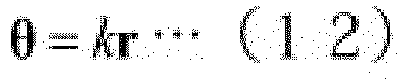
In Equation (12), the corneal reflection-pupil center vector r is known since the corneal reflection-pupil center vector r is obtained by thesecond computation unit 27b. A slope φ which is a component of the angle θ is an angle formed by the corneal reflection-pupil center vector r and the horizontal axis X'. Therefore, the slope φ is known. Then, the angle θ is obtained by obtaining the magnitude |θ| of the angle θ. The magnitude |θ| of the angle θ is obtained using Equation (13).
[Math. 13]
- That is, the magnitude |θ| of the angle θ is obtained by calculating an absolute value of the corneal reflection-pupil center vector r and multiplying the absolute value by a first coefficient k. Through the above process, the magnitude |θ| of the angle θ and the slope φ of the angle θ are obtained. As a result, the angle θ as the first optical axis candidate is obtained.
- A second line-of-sight detection process is executed in the second optical
axis acquisition unit 29. The second opticalaxis acquisition unit 29 obtains the second optical axis candidate by using the pupil shape method. In the pupil shape method, an angle θ corresponding to the optical axis AL is obtained. In the pupil shape method, it is assumed that the magnitude |θ| which is a component of the angle θ corresponds to a slope θS (seeFIG. 3(b) ). The slope θS is obtained by using Equation (14).
[Math. 14]
- In the pupil shape method, it is assumed that the slope φ which is a component of the angle θ corresponds to the slope γ' (see
FIG. 4 ). The second opticalaxis acquisition unit 29 obtains a slope γ' using a direction of the minor axis. Through the above-described process, the slope θS corresponding to the magnitude |θ| of the angle θ and the slope γ' corresponding to the slope φ of the angle θ are obtained. As a result, the angle θ as the second optical axis candidate is obtained. - The optical axis
information acquisition unit 31 selects any one of a process based on the corneal reflection-pupil center method and a process based on the pupil shape method as the line-of-sight detection process. This selection is based on the magnitude |θ| of the angle θ formed by the camera-pupil center vector OP and the optical axis AL (the line-of-sight vector PT). Specifically, when the magnitude |θ| of the angle θ is small, the optical axisinformation acquisition unit 31 selects the corneal reflection-pupil center method. This is because when the magnitude |θ| of the angle θ is small (θ≈0), a shape of an outer peripheral edge of the pupil P in the difference image approximates to a circular shape. That is, the difference between the major diameter and the minor diameter decreases. Therefore, a variation in the slope θS obtained from the ellipticity R tends to increases. This is because the slope θS is an inverse cosine component of the reciprocal of the ellipticity R. Therefore, when the magnitude |θ| of the angle θ is small (θ≈0), the corneal reflection-pupil center method can obtain a better result than the pupil shape method. On the other hand, the optical axisinformation acquisition unit 31 selects the pupil shape method when the magnitude |θ| of the angle θ is great. This is because, when the magnitude |θ| of the angle θ increases, a variation in the slope θS obtained from the ellipticity R tends to be small. Therefore, when the magnitude |θ| of the angle θ is great, the pupil shape method can obtain a better result than the corneal reflection-pupil center method. - Further, in the corneal reflection-pupil center method, when the magnitude |θ| of the angle θ is small, linearity (see Equation (1)) between the angle θ and the corneal reflection-pupil center vector r is high. Therefore, it is easy for detection accuracy of the line of sight to be made high. On the other hand, when the magnitude |θ| of the angle θ is great, it may be difficult to detect the corneal reflection G. Further, even when the corneal reflection G appears, nonlinearity appears and it is easy for white eye reflection to be erroneously detected due to image processing in a case in which the corneal reflection G is formed on the peripheral portion of the cornea.
- Therefore, the
image processing device 20 sets a threshold value. This threshold value is used to distinguish between a range in which linearity is dominant in the relationship between the corneal reflection-pupil center vector r and the angle θ (a range in which the corneal reflection G appears in most of the subjects M) and
a range in which non-linearity is dominant in the relationship between the corneal reflection-pupil center vector r and the angle θ. The magnitude |θ| of the angle θ = about 30 degrees is exemplified as the threshold value. The threshold value is not limited to 30 degrees, and a desired value may be used. Theimage processing device 20 obtains the magnitude |θ| of the angle θ for selecting the line-of-sight detection process by using the ellipticity R of the pupil P. Specifically, theimage processing device 20 obtains a slope θS corresponding to the magnitude |θ| of the angle θ. When the slope θS obtained from the ellipticity R is smaller than the threshold value, the optical axisinformation acquisition unit 31 selects a result of the corneal reflection-pupil center method and outputs the first optical axis candidate to the visualaxis acquisition unit 32. On the other hand, when the slope θS obtained from the ellipticity R is greater than the threshold value, the optical axisinformation acquisition unit 31 selects a result of the pupil shape method and outputs the second optical axis candidate to the visualaxis acquisition unit 32. - A process of acquiring the visual axis is executed in the visual
axis acquisition unit 32. The process of acquiring the visual axis is a process of calibrating a deviation of the optical axis AL from the visual axis AS. For example, when the first optical axis candidate is output to the visualaxis acquisition unit 32 as the optical axis AL1, the visualaxis acquisition unit 32 performs a process shown in Equation (15). That is, the visualaxis acquisition unit 32 executes a vector calculation for subtracting the deviation angle θ0 from the angle θAL1 as the optical axis AL. In Equation (15), the slope θS is the visual axis AS. The angle θAL1 is the first optical axis candidate.
[Math. 15]
- When the second optical axis candidate is output as the optical axis AL to the visual
axis acquisition unit 32, the visualaxis acquisition unit 32 performs the process shown in Equation (16). That is, the visualaxis acquisition unit 32 executes a vector calculation for subtracting the deviation angle θ0 from the angle θAL2 as the optical axis AL. In Equation (16), the slope θS is the visual axis AS. The angle θAL2 is the second optical axis candidate.
[Math. 16]
- The line-of-
sight detection device 1 includes a first opticalaxis acquisition unit 28 and a second opticalaxis acquisition unit 29. The first opticalaxis acquisition unit 28 obtains the optical axis AL using the position PS of the pupil center and the position GS of the corneal reflection. Therefore, the line-of-sight detection device 1 can perform line-of-sight detection in a range of the line of sight in which the corneal reflection G is obtained. The second opticalaxis acquisition unit 29 obtains the optical axis AL using the shape of the pupil P. Therefore, the line-of-sight detection device 1 can perform line-of-sight detection even in a range of the line of sight in which the corneal reflection G cannot be obtained. The optical axisinformation acquisition unit 31 obtains information for selecting any one of the first opticalaxis acquisition unit 28 and the second opticalaxis acquisition unit 29 using the shape of the pupil P. In the visualaxis acquisition unit 32, a deviation between the optical axis AL and the visual axis AS of the selected optical axis candidate is calibrated, and the visual axis AS as a line of sight is obtained. Therefore, the line-of-sight detection device 1 can extend the range in which the line of sight can be satisfactorily detected, from a narrow line-of-sight range in which the corneal reflection G can be obtained to a wide line-of-sight range in which the corneal reflection G cannot be obtained. - That is, according to the line-of-
sight detection device 1, it is possible to execute the corneal reflection-pupil center method and the pupil shape method on the same platform (a foundation or a basic theory). - In the corneal reflection-pupil center method, the line of sight (or a gazing point) is detected by using the relative position between the position GS of the corneal reflection and the position PS of the pupil center obtained from the image. In the pupil shape method, the line of sight (or the gazing point) is detected by using the shape of the pupil P defined by the ellipticity R and the direction of the minor axis.
- Specifically, in the corneal reflection-pupil center method, three-dimensional coordinates of the pupil P is obtained using the
optical system 15 in which thecamera 10 is calibrated. Next, the corneal reflection-pupil center method obtains the angle θ between the camera-pupil center vector OP and the optical axis AL of theeyeball 50. These are obtained using the corneal reflection-pupil center vector OP and the corneal reflection-pupil center vector r obtained from the image. On the other hand, in the pupil shape method, first, three-dimensional coordinates of the pupil P are obtained. Then, in the pupil shape method, the camera-pupil center vector OP is obtained. Then, the angle θ is obtained. The angle θ is obtained using the ellipticity R of the ellipse indicating the outer shape of the pupil P and the direction of the minor axis. Therefore, according to the line-of-sight detection device 1, the corneal reflection-pupil center method and the pupil shape method can be executed on the same platform. - Further, the line-of-
sight detection device 1 causes the subject M to gaze at a visual target for calibration of which coordinates are known in the cornea reflection-pupil center method. As a result, the line-of-sight detection device 1 obtains the deviation between the visual axis AS (the direction vector of the visual axis AS) and the optical axis AL (the direction vector of the optical axis) as the deviation angle θ0. A process of obtaining this deviation is called user calibration or gazing point calibration. When the line-of-sight detection process (or the gazing point detection process) is performed, an output result acquired as the optical axis AL is calibrated using the deviation angle θ0. As a result, it is possible to obtain the visual axis AS. Similarly, in the pupil shape method, it is possible to use the deviation angle θ0 clarified by user calibration for calibration of the output result acquired as the optical axis AL. - More specifically, the line-of-
sight detection device 1 performs calibration of the deviation between the visual axis AS and the optical axis AL at a rear stage in the process of obtaining the line of sight. In other words, the line-of-sight detection device 1 performs a calibration process after the process of obtaining the optical axis AL. According to this configuration, even when processes of obtaining the optical axis AL are different processes, a result obtained from these processes is the optical axis AL. Therefore, it is possible to easily execute the calibration process. - It should be noted that the calibration process may be a process of calibrating by viewing one point (a one-point calibration method) or may be another process. Then, for example, when the visual target presented at the center of the screen is viewed for a moment, the corneal reflection-pupil center method is executed. As a result, calibration information (deviation angle θ0) is obtained. In a case in which the subject M views a position greatly far away from the
optical system 15, the calibration information (the deviation angle θ0) can also be used even when the pupil shape method is applied. Therefore, a burden on the subject M with respect to the calibration can be reduced. Further, the line-of-sight detection in a wide angle range becomes possible as compared with a case in which only the corneal reflection-pupil center method is used. - According to an experiment of the inventors, a range in which predetermined line-of-sight detection accuracy in the line-of-
sight detection device 1 can be obtained is ±45 degrees in the horizontal direction with reference to the corneal reflection-pupil center vector OP. This range was confirmed by actually performing experiments. Further, it is assumed that the size |θ| of the angle θ = 60 degrees as a detection range. In this case, the ellipticity R (the ratio of the minor diameter to the major diameter) is 0.5. Therefore, by improving the image processing and controlling the light source, at least about |θ| = 60 degrees can be measured. It should be noted that examples of a remote line-of-sight detection device or gazing point detection device of which the detection range is 45 degrees or more have not been reported. - In the above description, the first coefficient k is included in Equation (17) of the corneal reflection-pupil center method.
[Math. 17]
- The first coefficient k may be treated as a constant value. Further, the first coefficient k may be treated as a changing value. For example, when the angle θ is small, a relationship between the angle θ and the corneal reflection-pupil center vector r has a high linearity in Equation (17). Therefore, the first coefficient k is treated as a constant value. On the other hand, when the angle θ is large, the relationship between the angle θ and the corneal reflection-pupil center vector r is has storing nonlinearity in Equation (17). Therefore, the first coefficient k is treated as a value that changes according to the corneal reflection-pupil center vector r. Further, the first coefficient k changes according to personality of the
eyeball 50 of the subject M. - Now, when the subject M views any point on the
display device 30, Equation (18) is obtained for each of thecameras 10. Here, thecamera 10L is disposed at a position (OS1), and thecamera 10R is disposed at a position (OS2). The corneal reflection G occurring in the left eye (first eye) is a position (GS1) and the corneal reflection G occurring in the right eye (second eye) is a position (GS2). Further, a pupil center position of the left eye is a position (PS1). A pupil center position of the right eye is a position (PS2). An angle θ1 indicates the visual axis AS obtained from thecamera 10L. An angle θ1' indicates the optical axis AL obtained from thecamera 10L. The angle θ0 indicates the deviation angle. A corneal reflection-pupil center vector r1 (a third vector) indicates a vector obtained from thecamera 10L. An angle θ2 indicates the visual axis AS obtained from thecamera 10R. The angle θ2' indicates the optical axis AL obtained from thecamera 10R. A corneal reflection-pupil center vector r2 (a fifth vector) indicates a vector that is obtained from thecamera 10R. Here, in Equation (18), since the first coefficient k and the deviation angle θ0 are unique to the eyeball, the first coefficient k and the deviation angle θ0 are common.
[Math. 18]
Equation (19) is obtained from Equation (18).
[Math. 19]
In Equation (19), the first coefficient k is a positive real number. Therefore, Equation (19) is shown as Equation (20).
[Math. 20]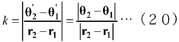
optical systems 15 as viewed from the pupil P. Therefore, it is possible to obtain the first coefficient k as a constant value by using Equation (20). It should be noted that according to Equation (20), even when the subject M views any visual target, the first coefficient k can be obtained for each frame. - When a relationship between the magnitude |r| of the corneal reflection-pupil center vector r and the angle θ is nonlinear, Equation (17) is shown as Equation (21).
[Math. 21]
- Further, Equation (21) is shown as Equation (22). In Equation (22), a function f is a nonlinear function. Therefore, when the function f is known, the first coefficient k can be obtained. Next, a method for obtaining the function f will be described.
[Math. 22]
- First, the function f indicates |θ| which is the magnitude of the angle θ and the magnitude |r| of the corneal reflection-pupil center vector r. In Equation (22), the slope φ' of the corneal reflection-pupil center vector r and the slope φ of the angle θ match each other. In other words, Equation (23) is obtained.
[Math. 23]
- According to Equation (23) above and the assumption, the slope φ' of the corneal reflection-pupil center vector r is obtained using the image obtained by the
camera 10 and the internal parameters of the camera. InFIG. 11 , two virtual optical axis planes VL1 and VL2 are shown for the twooptical systems 15. The intersection line CL of the virtual optical axis planes VL1 and VL2 corresponds to the optical axis AL. The virtual optical axis plane VL1 includes a position (OS1) of the first camera, a position (PS1) of the pupil center, and a position at which the first optical axis intersects the first virtual viewpoint plane. The first virtual viewpoint plane is a plane having a fourth vector directed from the first camera position (OS1) to the position (PS1) of the pupil center as a normal. The virtual optical axis plane VL2 includes the position (OS2) of the second camera, the position (PS2) of the pupil center, and a position at which the second optical axis intersects the second virtual viewpoint plane. The second virtual viewpoint plane is a plane having a sixth vector directed from the second camera position (OS2) to the position (PS2) of the pupil center as a normal. - According to the method of obtaining the optical axis AL, the optical axis AL can be obtained irrespective of the magnitude |r| of the corneal reflection-pupil center vector r and the magnitude |θ| of the angle θ. Obtaining the optical axis AL corresponds to obtaining the angle θ with respect to the
optical system 15. Therefore, a first coefficient (k1) corresponding to the left eye is obtained by using the fifth angle (θ1) and the magnitude (|r1|) of the third vector (r1). The fifth angle (θ1) is obtained from the intersection line at which the first virtual optical axis plane and the second virtual optical axis plane intersect each other and the fourth vector. Further, a first coefficient (k2) corresponding to the right eye is obtained using the fifth angle (θ2) obtained from the intersection line and the sixth vector and the magnitude (|r2|) of the fifth vector (r2). - The corneal reflection-pupil center vectors r1 and r2 are also obtained from the respective
optical systems 15. Therefore, it is possible to determine the nonlinear function f shown in Equation (23) by plotting a relationship between the magnitude |r| of the corneal reflection-pupil center vector r and the magnitude |θ| of the angle θ. It should be noted that the relationship between the magnitude |r| of the corneal reflection-pupil center vector r and the magnitude |θ| can be determined regardless of which direction the subject M is viewing. Therefore, it is possible to accumulate data while the subject M is viewing various directions. It should be noted that in this case, it is assumed that the position GS of the corneal reflection and the position PS of the pupil center can both be detected. - After the function f is acquired, the angle θ is obtained from the image acquired by the
camera 10 using the corneal reflection-pupil center vector r. Therefore, the optical axis AL of theeyeball 50 can be obtained for eachcamera 10. It should be noted that the function f acquired in advance may be repeatedly used. Further, the function f may be updated each time data is increased. When the subject M is caused to gaze at a visual target of which coordinates are known, the angle θ is obtained. At the same time, since the pupil P is obtained, it is possible to obtain the visual axis AS passing through the pupil P and the visual target position. - In the above description, the pupil shape method does not include a coefficient corresponding to the first coefficient k in the corneal reflection-pupil center method. However, also in the pupil shape method, it is possible to include the second coefficient h corresponding to the first coefficient k as in Equation (24).
[Math. 24]
- The second coefficient h may be treated as a constant value, similar to the first coefficient k. Further, the second coefficient h may be treated as a changing value. The second coefficient h is obtained by the same method as the method for the first coefficient k.
- The pupil P observes an object through the lens called the cornea. Therefore, as the angle of the line of sight with respect to the
camera 10 increases, a relationship between the ellipticity R and the angle θ deviates due to refraction of light caused by the cornea. Therefore, nonlinear calibration is required in the relationship between the ellipticity R and the angle θ. According to the process of acquiring the first coefficient k, the virtual optical axis planes VL1 and VL2 are obtained from information on only a minor-axis direction of the ellipse of the pupil P. Therefore, the process of acquiring the first coefficient k is not affected by the refraction. That is, it is not necessary to take refraction into consideration in the process of acquiring the first coefficient k. - The line-of-sight detection process is executed by repeating steps S11 to S18 described above. In the above description, the calibration information indicating the deviation between the optical axis AL and the visual axis AS has been described as the deviation angle θ0. This deviation angle θ0 is acquired in the calibration step that is performed before a repetitive process including steps S11 to S18.
- As illustrated in
FIG. 12 , when the subject M views a visual target A4 at a center, a visual axis AS1 directed from the pupil P of the subject M to the visual target A4 is formed. On the other hand, the optical axis AL1 is obtained by executing another process. An intersection T1 between the optical axis AL1 and thedisplay device 30 is obtained.FIG. 12 illustrates a virtual plane with the intersection T1 as an origin. This virtual plane is obtained by replacing the position of the camera of the virtual viewpoint plane inFIG. 12 with an intersection between the optical axis AL of the eyeball and the display. In this case, an intersection line between the virtual plane VP1 and an XZ plane (a horizontal plane) of the world coordinate system is defined as a horizontal axis of the virtual plane VP1. An intersection of the virtual plane VP1 and the visual axis AS is obtained. Conversion into a vector in a coordinate system of the virtual viewpoint plane is performed. As a result, calibration information (deviation angle θ0) indicating the deviation between the visual axis AS and the optical axis AL is obtained. - The present invention has been described in detail based on the embodiment thereof. However, the present invention is not limited to the above embodiment. The present invention can be variously modified without departing from the gist thereof.
- As illustrated in
FIG. 13 , theimage processing device 20A of the line-of-sight detection device 1 may include adirection determination unit 35. Thedirection determination unit 35 determines the direction of the visual axis AS with respect to the camera-pupil center vector OP. -
FIG. 14(a), (b), (c), and (d) illustrate a positional relationship between the pupil P of the subject M, aglow 55, and the corneal reflection G.FIG. 14(a) illustrates a positional relationship among the pupil P, theglow 55, and the corneal reflection G when the subject M views the visual target on the right side of thecamera 10.FIG. 14(b) illustrates a positional relationship among the pupil P, theglow 55, and the corneal reflection G when the subject M is viewing the visual target at a position on the right side of thecamera 10 and closer to thecamera 10 relative to the visual target inFIG. 14(a). FIG. 14(c) illustrates a positional relationship among the pupil P, theglow 55, and the corneal reflection G when the subject M views thecamera 10 or thelight source 13.FIG. 14(d) illustrates a positional relationship among the pupil P, theglow 55, and the corneal reflection G when the subject M views the visual target on the left side of thecamera 10.FIG. 14(e) illustrates a positional relationship among the pupil P, theglow 55, and the corneal reflection G when the subject M is viewing the visual target at a position on the left side of thecamera 10 and farther from thecamera 10 relative to the visual target inFIG. 14(d) . - As illustrated in
FIGS. 14(a) and 14(e) , the reflection image (the corneal reflection G) of the light emitted from thelight source 13 is generated outside the cornea. That is, the reflected image of the light emitted from thelight source 13 is generated in a white eye region. As illustrated inFIGS. 14(b) and 14(d) , a reflection image of the light emitted from thelight source 13 is generated at a position away from the pupil P on the cornea. As illustrated inFIG. 14(c) , a reflection image of the light emitted from thelight source 13 is generated at a position close to the pupil P on the cornea. - As illustrated in
FIGS. 14(a) and 14(d) , the reflection image generated in the white eye region is not stabilized due to nonuniformity of the shape of the white eye or the like. Therefore, the reflection image generated in the white eye region is not suitable for use in high-precision eye-line-of-sight detection. For example, a method of determining whether the subject views the right or views the left according to whether the reflection image generated in the white eye region exists on the left or right side of the pupil P is known. However, in an eyeglass reflection image of the light source generated when the subject wears eyeglasses, the characteristics of the image greatly changes according to the eyeglasses, the subject M, and an angle of the head of the subject M. In addition, the white eye reflection also changes. Therefore, it may be difficult to distinguish between the subject viewing the right and subject viewing the left using characteristics of the image. Further, white eye reflection may not appear according to the line-of-sight direction. Therefore, according to a determination of the line-of-sight direction using the reflected image, it may be difficult to determine the line-of-sight direction. - When
FIG. 14(a) is compared withFIG. 14(e) , the shape of the pupil P in the image is the same either when the subject views a left index or when the subject views a right index. Specifically, the ellipticity R indicating the shape of the pupil P is the same either when the subject views a left index or when the subject views a right index as long as the angle of the visual axis AS with respect to the camera-pupil center vector OP is the same. That is, in the method of using the ellipticity R of the pupil P, when the subject views indices at point-symmetric positions with theoptical system 15 interposed therebetween (for example, upper right and lower left), both cases cannot be distinguished since the cases indicate the same value of the ellipticity R. - Therefore, the
image processing device 20A may include thedirection determination unit 35. Thedirection determination unit 35 discriminates the line-of-sight direction with respect to the camera-pupil center vector OP.FIG. 15(a) illustrates a case in which the subject M views the right side of the twooptical systems optical system 15L of the subject M and a line of sight AG1 of the left eye. The slope α2 is a slope between the rightoptical system 15R and the line of sight AG2 of the left eye. As a result, the ellipticity R2 obtained from the image GRR of the rightoptical system 15R is greater than the ellipticity R1 obtained from the image GRL of the leftoptical system 15L. The same may apply to the right eye. Conversely, as illustrated inFIG. 15(b) , when the subject M greatly views the left side, the ellipticity R2 obtained from the image GRR of the rightoptical system 15R is greater than the ellipticity R1 obtained from the image GRL of the leftoptical system 15L. According to this method, rough distinguishment between the subject M viewing the right or viewing the left can be performed by comparing the ellipticity R1 and R2 of the pupil P included in the images GRL and GRR respectively acquired by the left and rightoptical systems - The line-of-
sight detection device 1 is not limited to the configuration of the functional block diagram illustrated inFIG. 9 . The line-of-sight detection device 1 may appropriately change a relationship between the respective functional blocks for efficiency of the process and the like. For example, in the line-of-sight detection device 1, the first opticalaxis acquisition unit 28 and the second opticalaxis acquisition unit 29 may include afirst computation unit 27a, asecond computation unit 27b, athird computation unit 27c, afourth computation unit 27d, afifth computation unit 27e, asixth computation unit 27f, and aseventh computation unit 27g constituting thecomputation unit 27. Further, the line-of-sight detection method is not limited to an order shown in the flowchart ofFIG. 10 , and the order of each step may be changed. For example, in the line of sight detection method, before the optical axis candidates are obtained in the first opticalaxis acquisition unit 28 and the second opticalaxis acquisition unit 29, the optical axis acquisition unit may be selected and the optical axis AL may be obtained only in the selected optical axis acquisition unit. Further, in the line of sight detection method, the process of calibrating the optical axis may be executed immediately after the first optical axis candidate is obtained, and the process of calibrating the optical axis may be executed immediately after the second optical axis candidate is obtained. In this case, in the line-of-sight detection method, the calibration process is executed twice in the process of obtaining one visual axis AS. - Meanwhile, the second optical
axis acquisition unit 29 of the line-of-sight detection device 1 according to the embodiment obtains the optical axis using the pupil shape. The pupil P is covered by the cornea 52 (seeFIG. 5 ). As a result, thecamera 10 outputs an image of the pupil P via thecornea 52. Then, refraction is likely to occur when the light passes through thecornea 52. Therefore, the position of the corneal contour on the image is likely to be deviated with respect to the position of the actual pupil contour. Therefore, the line-of-sight detection device 1 corrects the ellipticity R. As a result, a deviation of the position of the pupil contour on the image with respect to a position of the actual pupil contour is corrected. Specifically, the line-of-sight detection device 1 obtains the corrected ellipticity R' obtaining by correcting the ellipticity R. The line-of-sight detection device 1 performs the line-of-sight detection process using the corrected ellipticity R'. The correction of the ellipticity R may be executed by the second opticalaxis acquisition unit 29. In addition, the correction of the ellipticity R may be executed by thefourth computation unit 27d that obtains the ellipticity R. For example, Equation (25) is used for correction of the ellipticity R.
[Math. 25]
cornea 52 can be corrected. - The second optical
axis acquisition unit 29 may obtain the slope θS by directly using the inverse cosine component of the reciprocal of the ellipticity R (see Equation (7)). - The second optical
axis acquisition unit 29 may obtain the slope θS by directly using the inverse cosine component of the reciprocal of the corrected ellipticity R' (see Equation (26)).
[Math. 26]
- As shown in Equation (27), the second optical
axis acquisition unit 29 may multiply the inverse cosine component of the reciprocal of the corrected ellipticity R' by the second coefficient (h). As a result, a slope θS is also obtained as a corrected value.
[Math. 27]
- According to such a line-of-
sight detection device 1, it is possible to further improve the accuracy of the line-of-sight detection based on the pupil shape method. - The line-of-
sight detection device 1 according to the present embodiment also executes a process based on the pupil shape method on a platform that performs a process based on the cornea reflection-pupil center method. That is, the line-of-sight detection device 1 according to the present embodiment executes a process based on the cornea reflection-pupil center method and a process based on the pupil shape method on one platform. However, the present invention is not limited to such a platform, and the process based on the corneal reflection-pupil center method and the process based on the pupil shape method may be executed on a platform that executes another process. - For example, the process based on the corneal reflection-pupil center method and the process based on the pupil shape method may be executed on a platform that obtains a face posture of the subject M. The "face posture" referred to herein means a position and a direction of a skull of the subject M. The face posture is not related to a direction (for example, line of sight) of the eyeball of the subject M. For example, there is a Patent Literature (Japanese Unexamined Patent Publication No.
2007-26073 - First, a basic principle of the face detection method will be described. As illustrated in
FIG. 16 , the face posture of the subject M is indicated by a face posture vector VB. The face posture vector VB is obtained using the pupils and nostrils of the subject M. For example, the face posture vector VB is a normal vector of a plane passing through three points of a position PS1 of the left pupil center, a position PS2 of the right pupil center, and a position P0 of the center between the nostrils. The left pupil, the right pupil, the left nostril (first nostril) center, the right nostril (second nostril) center, and the center between the nostrils can be defined as feature points. Three-dimensional coordinates of these feature points can be obtained using several calculation schemes. - As illustrated in
FIG. 17 , the line-of-sight detection device 1B physically has the same configuration as the line-of-sight detection device 1 according to the embodiment. On the other hand, in the line-of-sight detection device 1B, functional components in theimage processing device 20B are different from those in the line-of-sight detection device 1. The line-of-sight detection device 1B includes a coordinateacquisition unit 26a and a faceposture acquisition unit 36 as functional components for detecting a face posture. The coordinateacquisition unit 26a is included in thepreprocessing unit 26B in thecalculation unit 23B. The faceposture acquisition unit 36 is included in thecalculation unit 23B. - The coordinate
acquisition unit 26a is a component of thepreprocessing unit 26. The coordinateacquisition unit 26a obtains three-dimensional coordinates regarding the positions (PS1, PS2) of the pupil center. Further, the coordinateacquisition unit 26a obtains three-dimensional coordinates regarding the positions (P0, NS1, NS2) of the nostrils. It should be noted that the coordinateacquisition unit 26a only has to be able to obtain the three-dimensional coordinates. Therefore, the coordinateacquisition unit 26a does not have to be a component of thepreprocessing unit 26. Using the first image acquired by thefirst camera 10L and the second image acquired by thesecond camera 10R, the coordinateacquisition unit 26a obtains three-dimensional coordinates of the position (PS1, PS2) of the pupil center and three-dimensional coordinates of the positions (P0, NS1, NS2) of the nostrils using the stereo matching method. - Specifically, the coordinate
acquisition unit 26a performs the following operation. As illustrated inFIG. 18 , three coordinate systems are used for a determination of the three-dimensional coordinates of the pupil center using the stereo method. The three coordinate systems are a world coordinate system CW (XW, YW, ZW), a camera coordinate system CC (XC, YC, ZC), and an image coordinate system CG (XG, YG, ZG). The world coordinate system CW defines any point to be shared among a plurality of cameras. The three-dimensional coordinates of the feature point are based on the world coordinate system CW. A relationship between the world coordinate system CW and the camera coordinate system CC is shown by Equation (28). A rotation matrix MR and a translation vector TR in Equation (28) are constants that are obtained through camera calibration. The coordinateacquisition unit 26a obtains the position (PS1, PS2) of the pupil center in the world coordinate system CW using Equation (28).
[Math. 28]
- The face
posture acquisition unit 36 obtains a face posture vector using the three-dimensional coordinates of the position (PS1, PS2) of the pupil center and three-dimensional coordinates of the positions (NS1, NS2) of the nostrils. - The face
posture acquisition unit 36 obtains three reference parts using four pieces of coordinate information (PS1, PS2, NS1, NS2). A set of three reference parts is a reference part group. Then, the faceposture acquisition unit 36 sets a virtual plane. The virtual plane is a triangular plane of which a vertex is a point indicated by the three generated reference parts. The faceposture acquisition unit 36 obtains a face posture vector VB passing through a centroid of the virtual plane. The face posture vector VB is information indicating the face posture. - For example, the face
posture acquisition unit 36 may select the position PS1 of the pupil center of the right eye, the position PS2 of the pupil center of the left eye, and the position P0 of the center of the nostrils as the reference part group (seeFIG. 16 ). The position P0 of the center between the nostrils is an average of the position NS1 of the right nostril and the position NS2 of the left nostril. The faceposture acquisition unit 36 selects the position PS1 of the pupil center of the right eye, the position PS2 of the pupil center of the left eye, and the position NS1 of the right nostril as the first reference part group. The faceposture acquisition unit 36 obtains a first normal vector using these. In addition, the faceposture acquisition unit 36 selects the position PS1 of the pupil center of the right eye, the position PS2 of the pupil center of the left eye, and the position NS2 of the left nostril as a second reference part group. The faceposture acquisition unit 36 obtains a second normal vector using these. It should be noted that the faceposture acquisition unit 36 may obtain an average of the first normal vector and the second normal vector as the face posture vector VB. - The line-of-
sight detection device 1B according to the modification example can extend the range in which the line of sight can be detected. Further, the line-of-sight detection device 1B can obtain a face posture of the subject M. - The operation of the coordinate acquisition unit is not limited to the process based on the stereo matching method. For an operation of the coordinate acquisition unit, any process may be selected as long as the process is a process capable of acquiring the three-dimensional coordinates of the pupil P and nostrils. For example, as illustrated in
FIG. 19 , the coordinateacquisition unit 26b may obtain three-dimensional coordinates through a process called a constraint condition method. In the constraint condition method, three-dimensional coordinates of feature points are obtained by using a distance between the feature points (hereinafter referred to as "inter-feature point distance" or simply a "distance") as constraint conditions. The inter-feature point distance is, for example, a distance L1 between the position PS1 of the left pupil center and the position PS2 of the right pupil center, a distance L2 between the position PS1 of the left pupil center and the position P0 of the center between the nostrils, and a distance L3 between the position PS2 of the right pupil center and the position P0 of the center between the nostrils (seeFIG. 16 ). Further, two optical systems (for example, cameras) are required to implement the stereo method. However, in the constraint condition method, three-dimensional coordinates can be obtained only with a third image acquired by one camera (a third camera). Therefore, according to the constraint condition method, it is possible to extend the detection range of the face direction in a separation direction of the optical system by disposing the two optical systems at a distance and using the respective optical systems. - As illustrated in
FIG. 19 , the line-of-sight detection device 1C physically has the same configuration as the line-of-sight detection device 1 according to the embodiment. On the other hand, in the line-of-sight detection device 1C, the functional components in theimage processing device 20C are different from the line-of-sight detection device 1. The line-of-sight detection device 1C has a coordinateacquisition unit 26b as a functional component for detecting the face posture. The coordinateacquisition unit 26b is included in thepreprocessing unit 26C in thecalculation unit 23C. The coordinateacquisition unit 26b includes adistance computation unit 26c, a two-dimensional coordinatecomputation unit 26d, and a three-dimensional coordinatecomputation unit 26e. Further, thecalculation unit 23C includes a faceposture acquisition unit 36. - The imaging optical system in the line-of-
sight detection device 1C can be assumed to be a pinhole model with a focal length f (seeFIG. 20 ). Two-dimensional coordinates of center points of the right pupil, the left pupil, the left nostril, and the right nostril on a nostril image (imaging plane PL) in the camera coordinate system CC are Q1, Q2, Q3, and Q4. The camera coordinate system CC is assumed to be a position origin OR of the pinhole. Using the two-dimensional coordinates of the four points, the preprocessingunit 26 obtains coordinates (inter-nostril center coordinates) P0 of a midpoint of both nostrils (a center between the nostrils), the position PS1 of the right pupil center, and the position PS2 of the left pupil center. Here, Pn = (Xn, Yn, Zn) (n = 0, 1, 2). - A distance of each side of a triangle connecting the three feature points (the center between the nostrils, the left pupil, and the right pupil) is shown as a distance Lij between the points i and j (see Equation (29)) when any one of the points is i and the other points are j. This distance Lij is obtained through actual measurement that is performed in advance. A process of obtaining the distance Lij is executed by the
distance computation unit 26c.
[Math. 29]
- The two-dimensional position on the imaging plane PL corresponding to each feature point is shown by using a position vector from the pinhole to each feature point and the focal length f of the camera (see Equation (29)). The process of obtaining the two-dimensional position on the imaging plane PL is executed by the two-dimensional coordinate
computation unit 26d.
[Math. 30]
[Math. 31]
- The position vector of each feature point is shown by Equation (31) using the constant an (n = 0, 1, 2).
[Math. 32]
- Then, Equation (33) is established.
[Math. 33]
- Accordingly, Equation (34) is obtained.
[Math. 34]
- The face
posture acquisition unit 36 obtains a0, a1, and a2 using a simultaneous Equation (Equation (34)). The faceposture acquisition unit 36 applies a solution to the simultaneous equation to Equation (32). As a result, the faceposture acquisition unit 36 obtains a position vector. The position vector indicates three-dimensional coordinates of each feature point. The process of obtaining the three-dimensional coordinates is executed by the three-dimensional coordinatecomputation unit 26e. - The line-of-
sight detection device 1C according to the modification example can extend the range in which the line of sight can be detected. Further, the line-of-sight detection device 1C can obtain a face posture of the subject M. - In the above embodiment, the information generated by the optical axis
information acquisition unit 31 is information for selecting one of the first optical axis candidate and the second optical axis candidate as the optical axis AL. For example, the information generated by the optical axisinformation acquisition unit 31 may be information for generating the optical axis AL using both the first optical axis candidate and the second optical axis candidate (Equation (35)). In Equation (35), a weighting factor w1 is set in the information (magnitude |θ1|) of the first optical axis candidate, and a weighting factor w2 is set in information (magnitude |θ2|) of the second optical axis candidate. Therefore, the information generated by the optical axisinformation acquisition unit 31 may be the information indicating Equation (35) and the weighting factors w1 and w2 in Equation (35).
[Math. 35]
- As illustrated in
FIGS. 21(a) and 21(b) , the weighting factors w1 and w2 can have values between 0 and 1 with the slope θS as a variable. As illustrated inFIG. 21(a) , a threshold value θT (for example, 30 degrees) is set and a predetermined numerical range including the threshold value θT is set. In a case in which the slope θS does not exist within the predetermined numerical range and the slope θS exists on the side smaller than the predetermined numerical range, the weighting factor w1 is set to 1 and the weighting factor w2 is set to 0. On the other hand, when the slope θS does not exist within the predetermined numerical range and the slope θS exists on the side greater than the predetermined numerical range, the weighting factor w1 is set to 0 and the weighting factor w2 is set to 1. In other words, when the slope θS exists on the side smaller than the predetermined numerical range, the first optical axis candidate is set as the optical axis AL. On the other hand, when the slope θS exists on the side greater than the predetermined numerical range, the second optical axis candidate is set as the optical axis AL. Further, when the slope θS is within the predetermined numerical range, the optical axis AL may be obtained using the weighting factor w1 and the weighting factor w2. For example, when the slope θS is equal to the threshold value θT, the weighting factor w1 may be set to 0.5 and the weighting factor w2 may be set to 0.5. Further, as illustrated inFIG. 21(b) , a relationship between the weighting factors w1 and w2 and the slope θS may be changed stepwise. In this case, when the slope θS is smaller than the threshold value θT, the first optical axis candidate is used for acquisition of the optical axis AL. When the slope θS is greater than the threshold value θT, the second optical axis candidate is used for acquisition of the optical axis AL. That is, this is the same as the operation of the optical axisinformation acquisition unit 31 shown in the above embodiment. -
- 1 Line-of-sight detection device
- 10, 10L, 10R Camera (image acquisition unit)
- 11 Objective lens
- 12 Opening
- 13 Light source
- 13a, 13b Light emitting element
- 15 Optical system
- 20 Image processing device (Image processing unit)
- 21 Lighting control unit
- 22 Image input unit
- 23 Calculation unit
- 24 Recording unit
- 26 Preprocessing unit
- 27 Computation unit
- 27a First computation unit
- 27b Second computation unit
- 27c Third computation unit
- 27d Fourth computation unit
- 27e Fifth computation unit
- 27f Sixth computation unit
- 28 First optical axis acquisition unit
- 29 Second optical axis acquisition unit
- 30 Display device
- 31 Optical axis information acquisition unit
- 32 visual axis acquisition unit
- 33 Calibration information unit
- 34 Coefficient unit
- 35 Direction determination unit
- 50 Eyeball
- 52 Cornea
- 53 Crystalline lens
- 56 Retina
- 57 Fovea centralis
- 101 CPU
- 102 Main storage device
- 103 Auxiliary storage device
- 104 Communication control unit
- 105 Input device
- 106 Output device
- A1, A2 Visual target
- A3 Axis line
- AL Optical axis
- AS Visual line
- CL Intersection line
- G Corneal reflection
- OP Camera-pupil center vector
- P, Pa, Pb, Pc pupil
- PQ, PT Line-of-sight vector
- Q, T Gazing point
- r, r1, r2 Corneal reflection-pupil center vector
- M Subject
- VS Virtual viewpoint plane
- VL1, VL2 Virtual optical axis plane.
Claims (12)
- A line-of-sight detection device comprising:an image acquisition unit that obtains a plurality of eye images including eyes of a subject;a light source that is disposed near the image acquisition unit and irradiates the subject with light for causing corneal reflection in the eye; andan image processing unit that acquires information on a pupil shape of the eye, a position (PS) of a pupil center and a position (GS) of corneal reflection included in the plurality of eye images using the plurality of eye images, and obtains a line of sight of the subject based on an acquired information,wherein the image processing unit includesa first optical axis acquisition unit that acquires a first optical axis candidate using the position (PS) of the pupil center and the position (GS) of the corneal reflection;a second optical axis acquisition unit that acquires a second optical axis candidate by using the pupil shape;an optical axis information acquisition unit that generates information for acquiring an optical axis using at least one of the first optical axis candidate and the second optical axis candidate on the basis of the pupil shape;a calibration information unit that provides calibration information indicating a deviation of the optical axis with respect to a visual axis of the eye; anda visual axis acquisition unit that obtains the visual axis as the line of sight by calibrating the optical axis using the calibration information.
- The line-of-sight detection device according to claim 1,
wherein the calibration information is a deviation angle (θ0), and
the deviation angle (θ0) is a vector indicating a deviation of the optical axis with respect to the visual axis, and is indicated by a magnitude (|θ0|) and a slope (φ0) of the optical axis with respect to the visual axis. - The line-of-sight detection device according to claim 1 or 2,
wherein the image processing unit includes
a first computation unit that obtains a first vector (OP) directed from a position (OS) of the image acquisition unit to the position (PS) of the pupil center;
a second computation unit that obtains a second vector (r) directed from the position (GS) of the corneal reflection to the position (PS) of the pupil center;
a third computation unit that obtains a virtual viewpoint plane having the first vector (OP) as a normal;
a fourth computation unit that approximates an outer shape of the pupil included in the plurality of eye images as an ellipse and obtains an ellipticity (R = LA/LB) indicated by a major diameter (LA) and a minor diameter (LB) of the ellipse; and
a fifth computation unit that obtains a slope (γ') between a minor axis of the ellipse and a horizontal axis,
the first optical axis acquisition unit acquires the first optical axis candidate indicated by a magnitude (|θ|) of an angle (θ) with reference to the first vector (OP) and a slope (φ) with reference to a horizontal axis included in the virtual viewpoint plane using a magnitude (|r|) of the second vector (r) associated with the magnitude (|θ|) of the angle (θ) and a slope (φ') formed by the second vector (r) associated with the slope (φ) and the horizontal axis, and
the second optical axis acquisition unit obtains the second optical axis candidate indicated by the magnitude (|θ|) of the angle (θ) with reference to the first vector (OP) and the slope (φ) with reference to the horizontal axis included in the virtual viewpoint plane using the ellipticity (R) associated with the magnitude (|θ|) of the angle (θ) and the slope (γ') associated with the slope (φ). - The line-of-sight detection device according to claim 3, wherein the first optical axis acquisition unit associates the magnitude (|r|) of the second vector (r) with the magnitude (|θ|) of the angle (θ) using a first coefficient (k).
- The line-of-sight detection device according to claim 4,
wherein the image acquisition unit includes a first camera that obtains a first eye image included in the plurality of eye images and that is disposed at a first camera position (OS1), and a second camera that obtains a second eye image included in the plurality of eye images and that is disposed at a second camera position (OS2),
the eye includes a first eye and a second eye,
the first eye includes a position (GS1) of first corneal reflection, a position (PS1) of a first pupil center, and a first optical axis,
the second eye includes a position (GS2) of second corneal reflection, a position (PS2) of a second pupil center, and a second optical axis,
the image processing unit further includes
a sixth computation unit that obtains information on a first virtual optical axis plane including the first camera position (OS1), the position (PS1) of the first pupil center, and a position at which the first optical axis intersects a first virtual viewpoint plane having a fourth vector as a normal on the basis of a third vector (r1) directed from the position (GS1) of the first corneal reflection to the position (PS1) of the first pupil center and the fourth vector from the first camera position (OS1) to the position (PS1) of the first pupil center using the first eye image;
a seventh computation unit that obtains information on a second virtual optical axis plane including the second camera position (OS2), the position (PS2) of the second pupil center, and a position at which the second optical axis intersects a second virtual viewpoint plane having a sixth vector as a normal on the basis of a fifth vector (r2) directed from the position (GS2) of the second corneal reflection to the position (PS2) of the second pupil center and the sixth vector from the second camera position (OS2) to the position (PS2) of the second pupil center using the second eye image; and
a coefficient unit that obtains the first coefficient (k), and
the coefficient unit obtains the first coefficient (k1) corresponding to the first eye using a fifth angle (θ1) obtained from an intersection line at which the first virtual optical axis plane and the second virtual optical axis plane intersect each other and a magnitude (|r1|) of the third vector (r1), and obtains the first coefficient (k2) corresponding to the second eye using a fifth angle (θ2) obtained from the intersection line and the sixth vector, and a magnitude (|r2|) of the fifth vector (r2). - The line-of-sight detection device according to claim 5,
wherein the fourth computation unit obtains a first ellipse (R1 = LA1/LB1) that is a ratio of a major diameter (LA1) to a minor diameter (LB1) of the ellipse indicating an outer shape of the pupil included in the first eye image using the first eye image, and acquires a second ellipse (R2 = LA2/LB2) which is a ratio of a major diameter (LA2) to a minor diameter (LB2) of the ellipse indicating an outer shape of the pupil included in the second eye image using the second eye image, and
the image processing unit further includes a direction determination unit that compares the first ellipse (R1) with the second ellipse (R2) to distinguish a line-of-sight direction of the subject in a horizontal direction. - The line-of-sight detection device according to any one of claims 3 to 6, wherein the second optical axis acquisition unit associates an inverse cosine component of a reciprocal of the ellipticity (R) with the magnitude (|θ|) of the angle (θ) using a second coefficient (h).
- The line-of-sight detection device according to any one of claims 3 to 7, wherein the second optical axis acquisition unit uses a corrected ellipticity (R') obtained by correcting the deviation of a pupil contour caused by refraction of a cornea of an eyeball of the subject in acquisition of the magnitude (|θ|) of the angle (θ).
- The line-of-sight detection device according to any one of claims 1 to 8,
wherein the eye includes a first eye and a second eye, and
the image processing unit further includes a coordinate acquisition unit that acquires respective three-dimensional coordinates of a position (PS1) of the pupil center in the first eye, a position (PS2) of the pupil center in the second eye, a position (NS1) of a first nostril among a pair of nostrils of the subject, and a position (NS2) of a second nostril among the pair of nostrils of the subject; and
a face posture acquisition unit that acquires a face posture of the subject using the position (PS1) of the pupil center, the position (PS2) of the pupil center, the position (NS1) of the first nostril, and the position (NS2) of the second nostril. - The line-of-sight detection device according to claim 9,
wherein the image acquisition unit include a first camera that obtains a first image including a face of the subject, and a second camera that is disposed at a position separated from the first camera and obtains a second image including the face of the subject, and
the coordinate acquisition unit acquires the respective three-dimensional coordinates of the position (PS1) of the pupil center in the first eye, the position (PS2) of the pupil center in the second eye, the position (NS1) of the first nostril, and the position (NS2) of the second nostril using a stereo matching method based on the first image and the second image. - The line-of-sight detection device according to claim 10,
wherein the image acquisition unit includes one third camera that obtains a third image including a face of the subject, and
the coordinate acquisition unit includes
a distance computation unit that calculates a distance between three feature points generated from the first eye, the second eye, the first nostril, and the second nostril;
a two-dimensional coordinate computation unit that calculates two-dimensional coordinates of three feature points in the third image using the third image acquired by the third camera; and
a three-dimensional coordinate computation unit that calculates three-dimensional coordinates of each of the three generated feature points using the distance acquired by the distance computation unit and the two-dimensional coordinates acquired by the coordinate acquisition unit. - The line-of-sight detection device according to any one of claims 1 to 11, wherein the optical axis information acquisition unit generates information for selecting one of the first optical axis candidate and the second optical axis candidate as the optical axis on the basis of the pupil shape.
Applications Claiming Priority (2)
| Application Number | Priority Date | Filing Date | Title |
|---|---|---|---|
| JP2016158944 | 2016-08-12 | ||
| PCT/JP2017/029092 WO2018030515A1 (en) | 2016-08-12 | 2017-08-10 | Line-of-sight detection device |
Publications (3)
| Publication Number | Publication Date |
|---|---|
| EP3499462A1 true EP3499462A1 (en) | 2019-06-19 |
| EP3499462A4 EP3499462A4 (en) | 2020-01-08 |
| EP3499462B1 EP3499462B1 (en) | 2021-03-10 |
Family
ID=61162331
Family Applications (1)
| Application Number | Title | Priority Date | Filing Date |
|---|---|---|---|
| EP17839579.4A Active EP3499462B1 (en) | 2016-08-12 | 2017-08-10 | Line-of-sight detection device |
Country Status (4)
| Country | Link |
|---|---|
| US (1) | US10902635B2 (en) |
| EP (1) | EP3499462B1 (en) |
| JP (1) | JP6963820B2 (en) |
| WO (1) | WO2018030515A1 (en) |
Families Citing this family (21)
| Publication number | Priority date | Publication date | Assignee | Title |
|---|---|---|---|---|
| EP3499462B1 (en) * | 2016-08-12 | 2021-03-10 | National University Corporation Shizuoka University | Line-of-sight detection device |
| CN107357429B (en) * | 2017-07-10 | 2020-04-07 | 京东方科技集团股份有限公司 | Method, apparatus, and computer-readable storage medium for determining gaze |
| JP6840697B2 (en) * | 2018-03-23 | 2021-03-10 | 株式会社豊田中央研究所 | Line-of-sight direction estimation device, line-of-sight direction estimation method, and line-of-sight direction estimation program |
| JP7063045B2 (en) * | 2018-03-26 | 2022-05-09 | 株式会社Jvcケンウッド | Line-of-sight detection device, line-of-sight detection method and line-of-sight detection program |
| CN109064705A (en) * | 2018-07-10 | 2018-12-21 | 上海小蚁科技有限公司 | The method for early warning and device of the inspection of article point, calculate equipment at storage medium |
| KR102537784B1 (en) * | 2018-08-17 | 2023-05-30 | 삼성전자주식회사 | Electronic device and control method thereof |
| TWI704473B (en) * | 2018-11-16 | 2020-09-11 | 財團法人工業技術研究院 | Vision vector detecting method and device |
| WO2020154524A1 (en) * | 2019-01-25 | 2020-07-30 | Magic Leap, Inc. | Eye-tracking using images having different exposure times |
| US12067162B2 (en) * | 2019-07-10 | 2024-08-20 | Nec Corporation | Gaze point detection device and gaze point detection method |
| CN110488982B (en) * | 2019-08-26 | 2023-06-02 | 业成科技(成都)有限公司 | Eye-tracking electronic whiteboard device |
| JP6717477B1 (en) * | 2019-09-13 | 2020-07-01 | 株式会社スワローインキュベート | Image processing method, image processing apparatus, and image processing program |
| CN111208904A (en) * | 2020-01-08 | 2020-05-29 | 北京未动科技有限公司 | Sight estimation equipment performance evaluation method, system and equipment |
| CN111208905A (en) * | 2020-01-08 | 2020-05-29 | 北京未动科技有限公司 | Multi-module sight tracking method and system and sight tracking equipment |
| JP6757949B1 (en) * | 2020-05-28 | 2020-09-23 | 株式会社スワローインキュベート | Image processing method, image processing device, and image processing program |
| US11195301B1 (en) * | 2020-07-26 | 2021-12-07 | Nec Corporation Of America | Estimation of head yaw in an image |
| US12271519B2 (en) * | 2021-06-08 | 2025-04-08 | Huawei Technologies Co., Ltd. | Systems, methods, and media for eye tracking using statistically derived linear functions |
| JP7633885B2 (en) * | 2021-06-08 | 2025-02-20 | 矢崎総業株式会社 | Gaze Estimation System |
| CN113808160B (en) * | 2021-08-05 | 2024-01-16 | 虹软科技股份有限公司 | Gaze direction tracking method and device |
| EP4432050A4 (en) * | 2021-12-20 | 2025-03-05 | Samsung Electronics Co., Ltd. | DEVICE AND METHOD FOR CONTROLLING LIGHT SOURCES IN GAZE TRACKING WITH VISION |
| US20240099579A1 (en) * | 2022-09-26 | 2024-03-28 | Topcon Corporation | Ophthalmic apparatus |
| CN116758139B (en) * | 2023-06-26 | 2026-03-24 | 深圳市联影高端医疗装备创新研究院 | Three-dimensional brain midline detection methods, devices, computer equipment, and storage media |
Family Cites Families (15)
| Publication number | Priority date | Publication date | Assignee | Title |
|---|---|---|---|---|
| US5913079A (en) * | 1995-07-31 | 1999-06-15 | Canon Kabushiki Kaisha | Optical apparatus having a line of sight detection device |
| US7533989B2 (en) | 2003-12-25 | 2009-05-19 | National University Corporation Shizuoka University | Sight-line detection method and device, and three-dimensional view-point measurement device |
| JP4517049B2 (en) | 2003-12-25 | 2010-08-04 | 国立大学法人静岡大学 | Gaze detection method and gaze detection apparatus |
| JP4604190B2 (en) * | 2004-02-17 | 2010-12-22 | 国立大学法人静岡大学 | Gaze detection device using distance image sensor |
| JP4501003B2 (en) | 2005-07-15 | 2010-07-14 | 国立大学法人静岡大学 | Face posture detection system |
| JP4431749B2 (en) * | 2006-03-31 | 2010-03-17 | 国立大学法人静岡大学 | Face posture detection method |
| EP2171527B1 (en) * | 2007-07-26 | 2019-09-04 | Essilor International | Method for measuring at least one geometrical/physiognomical parameter for the fitting of a sight correcting glasses frame on the face of a user |
| US8885882B1 (en) * | 2011-07-14 | 2014-11-11 | The Research Foundation For The State University Of New York | Real time eye tracking for human computer interaction |
| ES2911679T3 (en) * | 2011-10-22 | 2022-05-20 | Alcon Inc | Apparatus for monitoring one or more surgical parameters of the eye |
| US8824779B1 (en) * | 2011-12-20 | 2014-09-02 | Christopher Charles Smyth | Apparatus and method for determining eye gaze from stereo-optic views |
| JP6265348B2 (en) * | 2013-05-22 | 2018-01-24 | 国立大学法人神戸大学 | Eye-gaze measuring device, eye-gaze measuring method, and eye-gaze measuring program |
| JP6346525B2 (en) | 2014-08-29 | 2018-06-20 | アルプス電気株式会社 | Gaze detection device |
| CN107003752B (en) * | 2014-12-17 | 2020-04-10 | 索尼公司 | Information processing apparatus, information processing method, and program |
| JP2017129898A (en) * | 2016-01-18 | 2017-07-27 | ソニー株式会社 | Information processing apparatus, information processing method, and program |
| EP3499462B1 (en) * | 2016-08-12 | 2021-03-10 | National University Corporation Shizuoka University | Line-of-sight detection device |
-
2017
- 2017-08-10 EP EP17839579.4A patent/EP3499462B1/en active Active
- 2017-08-10 JP JP2018533562A patent/JP6963820B2/en active Active
- 2017-08-10 US US16/324,583 patent/US10902635B2/en active Active
- 2017-08-10 WO PCT/JP2017/029092 patent/WO2018030515A1/en not_active Ceased
Also Published As
| Publication number | Publication date |
|---|---|
| EP3499462A4 (en) | 2020-01-08 |
| JPWO2018030515A1 (en) | 2019-06-13 |
| US20190172222A1 (en) | 2019-06-06 |
| WO2018030515A1 (en) | 2018-02-15 |
| JP6963820B2 (en) | 2021-11-10 |
| US10902635B2 (en) | 2021-01-26 |
| EP3499462B1 (en) | 2021-03-10 |
Similar Documents
| Publication | Publication Date | Title |
|---|---|---|
| EP3499462B1 (en) | Line-of-sight detection device | |
| EP3153092B1 (en) | Pupil detection system, gaze detection system, pupil detection method, and pupil detection program | |
| JP6631951B2 (en) | Eye gaze detection device and eye gaze detection method | |
| US11068056B2 (en) | Wearable eye tracking system with slippage detection and correction | |
| US20240046432A1 (en) | Compensation for deformation in head mounted display systems | |
| EP4180920A1 (en) | Adaptive parameters in image regions based on eye tracking information | |
| US20170352183A1 (en) | Face and eye tracking using facial sensors within a head-mounted display | |
| JP6596678B2 (en) | Gaze measurement apparatus and gaze measurement method | |
| EP3075304B1 (en) | Line-of-sight detection assistance device and line-of-sight detection assistance method | |
| US10430988B2 (en) | Facial animation using facial sensors within a head-mounted display | |
| US11624907B2 (en) | Method and device for eye metric acquisition | |
| CN108351514A (en) | Use the eye tracks of structure light | |
| EP2604180A1 (en) | Gaze point detection method and gaze point detection device | |
| JP6324119B2 (en) | Rotation angle calculation method, gazing point detection method, information input method, rotation angle calculation device, gazing point detection device, information input device, rotation angle calculation program, gazing point detection program, and information input program | |
| US20210405741A1 (en) | Detecting eye measurements | |
| WO2017209777A1 (en) | Face and eye tracking and facial animation using facial sensors within a head-mounted display | |
| US12271519B2 (en) | Systems, methods, and media for eye tracking using statistically derived linear functions | |
| JP6288770B2 (en) | Face detection method, face detection system, and face detection program | |
| JP6452236B2 (en) | Eyeball identification device and eyeball identification method | |
| JP7046347B2 (en) | Image processing device and image processing method | |
| JP2019215688A (en) | Visual line measuring device, visual line measurement method and visual line measurement program for performing automatic calibration | |
| JP2016099759A (en) | Face detection method, face detection device, and face detection program | |
| JP6906943B2 (en) | On-board unit | |
| EP4318379A1 (en) | Sparse color reconstruction using deep neural networks | |
| CN114761999A (en) | Image processing method, image processing apparatus, and image processing program |
Legal Events
| Date | Code | Title | Description |
|---|---|---|---|
| STAA | Information on the status of an ep patent application or granted ep patent |
Free format text: STATUS: THE INTERNATIONAL PUBLICATION HAS BEEN MADE |
|
| PUAI | Public reference made under article 153(3) epc to a published international application that has entered the european phase |
Free format text: ORIGINAL CODE: 0009012 |
|
| STAA | Information on the status of an ep patent application or granted ep patent |
Free format text: STATUS: REQUEST FOR EXAMINATION WAS MADE |
|
| 17P | Request for examination filed |
Effective date: 20190308 |
|
| AK | Designated contracting states |
Kind code of ref document: A1 Designated state(s): AL AT BE BG CH CY CZ DE DK EE ES FI FR GB GR HR HU IE IS IT LI LT LU LV MC MK MT NL NO PL PT RO RS SE SI SK SM TR |
|
| AX | Request for extension of the european patent |
Extension state: BA ME |
|
| DAV | Request for validation of the european patent (deleted) | ||
| DAX | Request for extension of the european patent (deleted) | ||
| A4 | Supplementary search report drawn up and despatched |
Effective date: 20191210 |
|
| RIC1 | Information provided on ipc code assigned before grant |
Ipc: A61B 3/113 20060101ALI20191204BHEP Ipc: G06T 7/70 20170101AFI20191204BHEP Ipc: G06F 3/0346 20130101ALI20191204BHEP Ipc: G06T 7/73 20170101ALI20191204BHEP |
|
| GRAP | Despatch of communication of intention to grant a patent |
Free format text: ORIGINAL CODE: EPIDOSNIGR1 |
|
| STAA | Information on the status of an ep patent application or granted ep patent |
Free format text: STATUS: GRANT OF PATENT IS INTENDED |
|
| INTG | Intention to grant announced |
Effective date: 20201008 |
|
| GRAS | Grant fee paid |
Free format text: ORIGINAL CODE: EPIDOSNIGR3 |
|
| GRAA | (expected) grant |
Free format text: ORIGINAL CODE: 0009210 |
|
| STAA | Information on the status of an ep patent application or granted ep patent |
Free format text: STATUS: THE PATENT HAS BEEN GRANTED |
|
| AK | Designated contracting states |
Kind code of ref document: B1 Designated state(s): AL AT BE BG CH CY CZ DE DK EE ES FI FR GB GR HR HU IE IS IT LI LT LU LV MC MK MT NL NO PL PT RO RS SE SI SK SM TR |
|
| REG | Reference to a national code |
Ref country code: GB Ref legal event code: FG4D |
|
| REG | Reference to a national code |
Ref country code: AT Ref legal event code: REF Ref document number: 1370671 Country of ref document: AT Kind code of ref document: T Effective date: 20210315 Ref country code: CH Ref legal event code: EP |
|
| REG | Reference to a national code |
Ref country code: IE Ref legal event code: FG4D |
|
| REG | Reference to a national code |
Ref country code: DE Ref legal event code: R096 Ref document number: 602017034511 Country of ref document: DE |
|
| REG | Reference to a national code |
Ref country code: LT Ref legal event code: MG9D |
|
| PG25 | Lapsed in a contracting state [announced via postgrant information from national office to epo] |
Ref country code: BG Free format text: LAPSE BECAUSE OF FAILURE TO SUBMIT A TRANSLATION OF THE DESCRIPTION OR TO PAY THE FEE WITHIN THE PRESCRIBED TIME-LIMIT Effective date: 20210610 Ref country code: LT Free format text: LAPSE BECAUSE OF FAILURE TO SUBMIT A TRANSLATION OF THE DESCRIPTION OR TO PAY THE FEE WITHIN THE PRESCRIBED TIME-LIMIT Effective date: 20210310 Ref country code: NO Free format text: LAPSE BECAUSE OF FAILURE TO SUBMIT A TRANSLATION OF THE DESCRIPTION OR TO PAY THE FEE WITHIN THE PRESCRIBED TIME-LIMIT Effective date: 20210610 Ref country code: FI Free format text: LAPSE BECAUSE OF FAILURE TO SUBMIT A TRANSLATION OF THE DESCRIPTION OR TO PAY THE FEE WITHIN THE PRESCRIBED TIME-LIMIT Effective date: 20210310 Ref country code: HR Free format text: LAPSE BECAUSE OF FAILURE TO SUBMIT A TRANSLATION OF THE DESCRIPTION OR TO PAY THE FEE WITHIN THE PRESCRIBED TIME-LIMIT Effective date: 20210310 Ref country code: GR Free format text: LAPSE BECAUSE OF FAILURE TO SUBMIT A TRANSLATION OF THE DESCRIPTION OR TO PAY THE FEE WITHIN THE PRESCRIBED TIME-LIMIT Effective date: 20210611 |
|
| REG | Reference to a national code |
Ref country code: AT Ref legal event code: MK05 Ref document number: 1370671 Country of ref document: AT Kind code of ref document: T Effective date: 20210310 |
|
| REG | Reference to a national code |
Ref country code: NL Ref legal event code: MP Effective date: 20210310 |
|
| PG25 | Lapsed in a contracting state [announced via postgrant information from national office to epo] |
Ref country code: SE Free format text: LAPSE BECAUSE OF FAILURE TO SUBMIT A TRANSLATION OF THE DESCRIPTION OR TO PAY THE FEE WITHIN THE PRESCRIBED TIME-LIMIT Effective date: 20210310 Ref country code: LV Free format text: LAPSE BECAUSE OF FAILURE TO SUBMIT A TRANSLATION OF THE DESCRIPTION OR TO PAY THE FEE WITHIN THE PRESCRIBED TIME-LIMIT Effective date: 20210310 Ref country code: RS Free format text: LAPSE BECAUSE OF FAILURE TO SUBMIT A TRANSLATION OF THE DESCRIPTION OR TO PAY THE FEE WITHIN THE PRESCRIBED TIME-LIMIT Effective date: 20210310 |
|
| PG25 | Lapsed in a contracting state [announced via postgrant information from national office to epo] |
Ref country code: NL Free format text: LAPSE BECAUSE OF FAILURE TO SUBMIT A TRANSLATION OF THE DESCRIPTION OR TO PAY THE FEE WITHIN THE PRESCRIBED TIME-LIMIT Effective date: 20210310 |
|
| PG25 | Lapsed in a contracting state [announced via postgrant information from national office to epo] |
Ref country code: SM Free format text: LAPSE BECAUSE OF FAILURE TO SUBMIT A TRANSLATION OF THE DESCRIPTION OR TO PAY THE FEE WITHIN THE PRESCRIBED TIME-LIMIT Effective date: 20210310 Ref country code: AT Free format text: LAPSE BECAUSE OF FAILURE TO SUBMIT A TRANSLATION OF THE DESCRIPTION OR TO PAY THE FEE WITHIN THE PRESCRIBED TIME-LIMIT Effective date: 20210310 Ref country code: EE Free format text: LAPSE BECAUSE OF FAILURE TO SUBMIT A TRANSLATION OF THE DESCRIPTION OR TO PAY THE FEE WITHIN THE PRESCRIBED TIME-LIMIT Effective date: 20210310 Ref country code: CZ Free format text: LAPSE BECAUSE OF FAILURE TO SUBMIT A TRANSLATION OF THE DESCRIPTION OR TO PAY THE FEE WITHIN THE PRESCRIBED TIME-LIMIT Effective date: 20210310 |
|
| PG25 | Lapsed in a contracting state [announced via postgrant information from national office to epo] |
Ref country code: PT Free format text: LAPSE BECAUSE OF FAILURE TO SUBMIT A TRANSLATION OF THE DESCRIPTION OR TO PAY THE FEE WITHIN THE PRESCRIBED TIME-LIMIT Effective date: 20210712 Ref country code: PL Free format text: LAPSE BECAUSE OF FAILURE TO SUBMIT A TRANSLATION OF THE DESCRIPTION OR TO PAY THE FEE WITHIN THE PRESCRIBED TIME-LIMIT Effective date: 20210310 Ref country code: SK Free format text: LAPSE BECAUSE OF FAILURE TO SUBMIT A TRANSLATION OF THE DESCRIPTION OR TO PAY THE FEE WITHIN THE PRESCRIBED TIME-LIMIT Effective date: 20210310 Ref country code: RO Free format text: LAPSE BECAUSE OF FAILURE TO SUBMIT A TRANSLATION OF THE DESCRIPTION OR TO PAY THE FEE WITHIN THE PRESCRIBED TIME-LIMIT Effective date: 20210310 Ref country code: IS Free format text: LAPSE BECAUSE OF FAILURE TO SUBMIT A TRANSLATION OF THE DESCRIPTION OR TO PAY THE FEE WITHIN THE PRESCRIBED TIME-LIMIT Effective date: 20210710 |
|
| REG | Reference to a national code |
Ref country code: DE Ref legal event code: R097 Ref document number: 602017034511 Country of ref document: DE |
|
| PLBE | No opposition filed within time limit |
Free format text: ORIGINAL CODE: 0009261 |
|
| STAA | Information on the status of an ep patent application or granted ep patent |
Free format text: STATUS: NO OPPOSITION FILED WITHIN TIME LIMIT |
|
| PG25 | Lapsed in a contracting state [announced via postgrant information from national office to epo] |
Ref country code: ES Free format text: LAPSE BECAUSE OF FAILURE TO SUBMIT A TRANSLATION OF THE DESCRIPTION OR TO PAY THE FEE WITHIN THE PRESCRIBED TIME-LIMIT Effective date: 20210310 Ref country code: DK Free format text: LAPSE BECAUSE OF FAILURE TO SUBMIT A TRANSLATION OF THE DESCRIPTION OR TO PAY THE FEE WITHIN THE PRESCRIBED TIME-LIMIT Effective date: 20210310 Ref country code: AL Free format text: LAPSE BECAUSE OF FAILURE TO SUBMIT A TRANSLATION OF THE DESCRIPTION OR TO PAY THE FEE WITHIN THE PRESCRIBED TIME-LIMIT Effective date: 20210310 |
|
| 26N | No opposition filed |
Effective date: 20211213 |
|
| PG25 | Lapsed in a contracting state [announced via postgrant information from national office to epo] |
Ref country code: SI Free format text: LAPSE BECAUSE OF FAILURE TO SUBMIT A TRANSLATION OF THE DESCRIPTION OR TO PAY THE FEE WITHIN THE PRESCRIBED TIME-LIMIT Effective date: 20210310 |
|
| REG | Reference to a national code |
Ref country code: CH Ref legal event code: PL |
|
| PG25 | Lapsed in a contracting state [announced via postgrant information from national office to epo] |
Ref country code: MC Free format text: LAPSE BECAUSE OF FAILURE TO SUBMIT A TRANSLATION OF THE DESCRIPTION OR TO PAY THE FEE WITHIN THE PRESCRIBED TIME-LIMIT Effective date: 20210310 |
|
| REG | Reference to a national code |
Ref country code: BE Ref legal event code: MM Effective date: 20210831 |
|
| GBPC | Gb: european patent ceased through non-payment of renewal fee |
Effective date: 20210810 |
|
| PG25 | Lapsed in a contracting state [announced via postgrant information from national office to epo] |
Ref country code: LI Free format text: LAPSE BECAUSE OF NON-PAYMENT OF DUE FEES Effective date: 20210831 Ref country code: IT Free format text: LAPSE BECAUSE OF FAILURE TO SUBMIT A TRANSLATION OF THE DESCRIPTION OR TO PAY THE FEE WITHIN THE PRESCRIBED TIME-LIMIT Effective date: 20210310 Ref country code: CH Free format text: LAPSE BECAUSE OF NON-PAYMENT OF DUE FEES Effective date: 20210831 |
|
| PG25 | Lapsed in a contracting state [announced via postgrant information from national office to epo] |
Ref country code: IS Free format text: LAPSE BECAUSE OF FAILURE TO SUBMIT A TRANSLATION OF THE DESCRIPTION OR TO PAY THE FEE WITHIN THE PRESCRIBED TIME-LIMIT Effective date: 20210710 Ref country code: LU Free format text: LAPSE BECAUSE OF NON-PAYMENT OF DUE FEES Effective date: 20210810 |
|
| PG25 | Lapsed in a contracting state [announced via postgrant information from national office to epo] |
Ref country code: IE Free format text: LAPSE BECAUSE OF NON-PAYMENT OF DUE FEES Effective date: 20210810 Ref country code: GB Free format text: LAPSE BECAUSE OF NON-PAYMENT OF DUE FEES Effective date: 20210810 Ref country code: FR Free format text: LAPSE BECAUSE OF NON-PAYMENT OF DUE FEES Effective date: 20210831 Ref country code: BE Free format text: LAPSE BECAUSE OF NON-PAYMENT OF DUE FEES Effective date: 20210831 |
|
| PG25 | Lapsed in a contracting state [announced via postgrant information from national office to epo] |
Ref country code: CY Free format text: LAPSE BECAUSE OF FAILURE TO SUBMIT A TRANSLATION OF THE DESCRIPTION OR TO PAY THE FEE WITHIN THE PRESCRIBED TIME-LIMIT Effective date: 20210310 |
|
| PG25 | Lapsed in a contracting state [announced via postgrant information from national office to epo] |
Ref country code: HU Free format text: LAPSE BECAUSE OF FAILURE TO SUBMIT A TRANSLATION OF THE DESCRIPTION OR TO PAY THE FEE WITHIN THE PRESCRIBED TIME-LIMIT; INVALID AB INITIO Effective date: 20170810 |
|
| PG25 | Lapsed in a contracting state [announced via postgrant information from national office to epo] |
Ref country code: MK Free format text: LAPSE BECAUSE OF FAILURE TO SUBMIT A TRANSLATION OF THE DESCRIPTION OR TO PAY THE FEE WITHIN THE PRESCRIBED TIME-LIMIT Effective date: 20210310 |
|
| PG25 | Lapsed in a contracting state [announced via postgrant information from national office to epo] |
Ref country code: TR Free format text: LAPSE BECAUSE OF FAILURE TO SUBMIT A TRANSLATION OF THE DESCRIPTION OR TO PAY THE FEE WITHIN THE PRESCRIBED TIME-LIMIT Effective date: 20210310 |
|
| PG25 | Lapsed in a contracting state [announced via postgrant information from national office to epo] |
Ref country code: MT Free format text: LAPSE BECAUSE OF FAILURE TO SUBMIT A TRANSLATION OF THE DESCRIPTION OR TO PAY THE FEE WITHIN THE PRESCRIBED TIME-LIMIT Effective date: 20210310 |
|
| PGFP | Annual fee paid to national office [announced via postgrant information from national office to epo] |
Ref country code: DE Payment date: 20250821 Year of fee payment: 9 |