EP3499414A1 - Lightweight 3d vision camera with intelligent segmentation engine for machine vision and auto identification - Google Patents
Lightweight 3d vision camera with intelligent segmentation engine for machine vision and auto identification Download PDFInfo
- Publication number
- EP3499414A1 EP3499414A1 EP18213164.9A EP18213164A EP3499414A1 EP 3499414 A1 EP3499414 A1 EP 3499414A1 EP 18213164 A EP18213164 A EP 18213164A EP 3499414 A1 EP3499414 A1 EP 3499414A1
- Authority
- EP
- European Patent Office
- Prior art keywords
- database
- camera
- image
- resolution
- dimensional
- Prior art date
- Legal status (The legal status is an assumption and is not a legal conclusion. Google has not performed a legal analysis and makes no representation as to the accuracy of the status listed.)
- Granted
Links
Images



Classifications
-
- G—PHYSICS
- G06—COMPUTING OR CALCULATING; COUNTING
- G06V—IMAGE OR VIDEO RECOGNITION OR UNDERSTANDING
- G06V20/00—Scenes; Scene-specific elements
- G06V20/60—Type of objects
- G06V20/64—Three-dimensional [3D] objects
- G06V20/647—Three-dimensional [3D] objects by matching two-dimensional images to three-dimensional objects
-
- G—PHYSICS
- G06—COMPUTING OR CALCULATING; COUNTING
- G06F—ELECTRIC DIGITAL DATA PROCESSING
- G06F16/00—Information retrieval; Database structures therefor; File system structures therefor
- G06F16/50—Information retrieval; Database structures therefor; File system structures therefor of still image data
- G06F16/58—Retrieval characterised by using metadata, e.g. metadata not derived from the content or metadata generated manually
- G06F16/583—Retrieval characterised by using metadata, e.g. metadata not derived from the content or metadata generated manually using metadata automatically derived from the content
- G06F16/5838—Retrieval characterised by using metadata, e.g. metadata not derived from the content or metadata generated manually using metadata automatically derived from the content using colour
-
- G—PHYSICS
- G06—COMPUTING OR CALCULATING; COUNTING
- G06T—IMAGE DATA PROCESSING OR GENERATION, IN GENERAL
- G06T7/00—Image analysis
- G06T7/70—Determining position or orientation of objects or cameras
- G06T7/73—Determining position or orientation of objects or cameras using feature-based methods
- G06T7/75—Determining position or orientation of objects or cameras using feature-based methods involving models
-
- G—PHYSICS
- G06—COMPUTING OR CALCULATING; COUNTING
- G06V—IMAGE OR VIDEO RECOGNITION OR UNDERSTANDING
- G06V10/00—Arrangements for image or video recognition or understanding
- G06V10/20—Image preprocessing
- G06V10/25—Determination of region of interest [ROI] or a volume of interest [VOI]
-
- G—PHYSICS
- G06—COMPUTING OR CALCULATING; COUNTING
- G06V—IMAGE OR VIDEO RECOGNITION OR UNDERSTANDING
- G06V10/00—Arrangements for image or video recognition or understanding
- G06V10/40—Extraction of image or video features
- G06V10/42—Global feature extraction by analysis of the whole pattern, e.g. using frequency domain transformations or autocorrelation
- G06V10/422—Global feature extraction by analysis of the whole pattern, e.g. using frequency domain transformations or autocorrelation for representing the structure of the pattern or shape of an object therefor
-
- G—PHYSICS
- G06—COMPUTING OR CALCULATING; COUNTING
- G06V—IMAGE OR VIDEO RECOGNITION OR UNDERSTANDING
- G06V10/00—Arrangements for image or video recognition or understanding
- G06V10/40—Extraction of image or video features
- G06V10/46—Descriptors for shape, contour or point-related descriptors, e.g. scale invariant feature transform [SIFT] or bags of words [BoW]; Salient regional features
-
- G—PHYSICS
- G06—COMPUTING OR CALCULATING; COUNTING
- G06V—IMAGE OR VIDEO RECOGNITION OR UNDERSTANDING
- G06V20/00—Scenes; Scene-specific elements
- G06V20/60—Type of objects
- G06V20/64—Three-dimensional [3D] objects
- G06V20/653—Three-dimensional [3D] objects by matching three-dimensional models, e.g. conformal mapping of Riemann surfaces
-
- G—PHYSICS
- G06—COMPUTING OR CALCULATING; COUNTING
- G06T—IMAGE DATA PROCESSING OR GENERATION, IN GENERAL
- G06T2207/00—Indexing scheme for image analysis or image enhancement
- G06T2207/20—Special algorithmic details
- G06T2207/20212—Image combination
-
- G—PHYSICS
- G06—COMPUTING OR CALCULATING; COUNTING
- G06V—IMAGE OR VIDEO RECOGNITION OR UNDERSTANDING
- G06V2201/00—Indexing scheme relating to image or video recognition or understanding
- G06V2201/06—Recognition of objects for industrial automation
Definitions
- Three-dimensional (3D) imaging is a fast growing trend, especially in the Industrial Automation field, where embedded vision sensors are widely used.
- Range imaging techniques are spreading not only due to Stereoscopic or Structured Light approaches, but also with new image sensors designed to measure the pixel distance by various methods and technologies, such as time-of-flight (TOF) and light-field (aka plenoptic) cameras.
- TOF time-of-flight
- plenoptic light-field
- a relevant example of an industrial, entry-level apparatus is the TriSpector 1000 3D Vision Family manufactured by SICK AG of Waldkirch, Germany. Although a single optimal approach has not yet emerged, the possibility to equip a 3D camera with soft Artificial Intelligence is a very hot topic in the pattern recognition and machine vision community.
- An entry level, compact and lightweight single package apparatus combining a conventional two-dimensional (2D) camera with a three-dimensional (3D) depth image camera, capable to learn, through depth information, how to improve the performance of a set of 2D identification and machine vision algorithms in terms of speed-up (e.g. through regions of interests (ROIs)) and raw discriminative power.
- This is achieved by implementing an "Intelligent Segmentation Engine” (ISE) consisting of an expert system capable of learning and building an incremental history of the known objects, while receiving appropriate feedback from 2D algorithms.
- ISE Intelligent Segmentation Engine
- a method of object recognition in a hybrid 2D/3D vision system includes acquiring a three-dimensional image of an object into a vision device.
- the vision device has a processor coupled to a memory.
- Two-dimensional images of the object are acquired into the vision device.
- the three-dimensional image is associated with the two-dimensional images.
- the three-dimensional image is identified through three-dimensional shape recognition.
- the three-dimensional image is identified by comparing shapes in the three-dimensional image to objects in a database. A union of the shapes generates the three-dimensional image. If a member of the shapes of the three-dimensional image matches to one of the objects in the database, that one of the objects is matched to a region of interest from the two-dimensional images.
- the member of the shapes of the three-dimensional image that matches to the one of the objects is matched to the region of interest from the two-dimensional images to speed up an object recognition process.
- a new region of interest from the two-dimensional images is detected if another member of the shapes of the three-dimensional image does not match to another one of the objects in the database.
- the new region of interest matches to another member of the shapes of the three-dimensional image.
- a method of object recognition in a hybrid 2D/3D vision system includes acquiring a three-dimensional image of an object into a vision device.
- the vision device has a processor coupled to a memory.
- Two-dimensional images of the object are acquired into the vision device.
- the three-dimensional image is associated with the two-dimensional images.
- Shape descriptors are computed for the object.
- the shape descriptors for the object are compared to other shape descriptors that are stored in a database. If a shape descriptor of the object matches one of the other shape descriptors in the database, the object is designated as an old object that is already in the database. The object matches the old object in the database.
- the object is designated as a new object and the object is stored in the database.
- a weight factor or reinforcement is assigned to the object.
- the weight factor or reinforcement of the object is increased each time the shape descriptor of the object is used in a comparison and matches to one of the other shape descriptors.
- the object that is more frequently classified has a stronger reinforcement.
- the object that has a strongest reinforcement is used over other objects in the database with lesser reinforcements.
- a compact and portable device includes several components.
- the device is preferably configured to implement a method of object recognition according to one or both of the above mentioned aspects.
- a high-resolution two-dimensional (2D) camera is included in the device.
- a low-resolution three-dimensional (3D) camera is included in the device.
- a lighting system is shared by the 2D camera and 3D camera.
- the 2D camera and 3D camera are mounted together to have parallel optical axes.
- a first sensor of the 2D camera and a second sensor of the 3D camera point in a same direction and have similar viewing areas.
- the 3D camera is mounted on top of the 2D camera.
- the first sensor and the second sensor simultaneously capture a 2D image and 3D image of a same viewing area.
- the 3D image is mapped into the 2D image to form a composite image.
- the new region of interest is stored in the database or another database.
- the step of identifying comprises:
- the step of identifying comprises:
- the object is already in the database designated as the old object or the new object.
- the shape descriptors are the contours or shapes of items that are described.
- the low-resolution 3D camera has reduced 3D computational overload and power consumption.
- the high-resolution 2D camera and the low-resolution 3D camera have sensors optimized for the infrared (IR) range.
- IR infrared
- the high-resolution 2D camera has a sensor optimized for the visible range and the low-resolution 3D camera have a sensor optimized for the infrared (IR) range.
- IR infrared
- the high-resolution 2D camera and the low-resolution 2D camera simultaneously frame-grab an image.
- a 3D Time of Flight (TOF) image from the low-resolution 3D camera is mapped into the 2D image from the high-resolution 2D camera.
- TOF Time of Flight
- the proposed apparatus and method can be used in automatic identification and machine vision applications, where there is the need for a low-cost solution without depth accuracy requirements mandatory in case of volume dimensioning or body scanning.
- Combining a low cost 3D-TOF approach with a 2D high-resolution camera in a single package sensor together with an original machine learning segmentation method has some distinctive advantages:
- An embodiment of the invention consists of a compact, single package vision sensor 200 containing a standard high-resolution 2D camera 210 (brightness image) and a lower resolution 3D camera 220 (depth image) pair, mounted and calibrated in an optical and geometrical environment 230.
- the resulting, combined camera system 200 is a compact and portable device, with reduced 3D computational overload and power consumption.
- the combined camer system 200 includes a lighting system.
- system 200 will be shared by the two sensors 210 and 220 (both the sensors optimized for infrared (IR) range), but system 200 could also be composed of two different sensor types (IR-TOF sensor combined with 2D visible range sensor). Even if TOF cameras have less depth accuracy compared to other types of 3D sensors (e.g. laser scanners, structured light, or stereo vision systems), this is not a limitation for the intended purposes of the proposed invention, since it can benefit from the aid of a high-resolution 2D sensor. On the contrary, in respect to other 3D technologies, TOF cameras can be fitted to real-time applications where automatic acquisition of 3D models involves sensor movement.
- IR-TOF sensor e.g. laser scanners, structured light, or stereo vision systems
- the cameras 210 and 220 should be placed as close as possible to each other. It is proposed that the 3D TOF camera 220 be mounted on top of the 2D camera 210. Moreover, the two sensors 210 and 220 should have appropriate optical systems in order to share similar viewing areas. In this way, the 3D information can be matched to or mapped inside the 2D image. From an operational point of view, the image is frame grabbed simultaneously by both the cameras 210 and 220 and then the TOF image from camera 220 is mapped into the 2D image of camera 210 (a threshold can be applied to the depth image to discard background objects).
- a TOF sensor can be an industrial, entry level low-cost IR-based depth camera, with a low resolution (320x240 pixels or QVGA).
- the TOF camera 220 and the 2D camera 210 are calibrated, and a mapping is made from the depth data to the 2D image.
- Calibration of 2D and 3D images is a state-of-the-art process, quite similar to a stereo camera calibration problem. It is only a matter of starting from 3D coordinates of the TOF camera 220 to find the corresponding 2D coordinates instead of building 3D coordinates from two sets of 2D coordinates. Given the calibrated image, segmentation will be performed directly on the depth image from the TOF camera 220, without using 2D information from the 2D camera 210. This is a fundamental task for 3D vision, often the very first step. It consists of partitioning the corresponding digital image into groups of pixels (regions) with similar characteristics (e.g. color, intensity, texture, etc.) in order to simplify the detection and classification of objects in the scene.
- 3D image segmentation allows for subsequent 3D rendering of multiple objects and a quantitative analysis for their size, density and other parameters. Edges identified by edge detection are often disconnected while object segmentation needs closed region boundaries. There is no overlap between different regions and the union of all the segmented regions generates the entire image.
- Segmentation can also be applied to a stack of images (this is typical in medical imaging) so that the resulting contours can allow for 3D reconstructions through a kind of interpolation algorithm (e.g. Marching cubes).
- a kind of interpolation algorithm e.g. Marching cubes.
- Many algorithms and techniques have been proposed for image segmentation, especially in the biomedical field. Particularly, the selected technique must be matched with the application's specific knowledge to get the best results.
- ISE Intelligent Segmentation Engine 300 provided for the system 200. It consists of five main components, depth threshold computing 310, labeling 320, classification 330, assistant module 340, and objects 350, designed to achieve automatic segmentation and classification while providing "expert information" to 2D algorithms.
- a set of depth thresholds are computed (310) in order to extract labeled regions (e.g. foreground, background, etc.) from the depth image of camera 220. It should be noted that a unique global threshold generally fails to detect all objects. Many known algorithms are available for this task.
- Classified objects can be either new objects or object already found in past images as determine in assistant module 340.
- a set of specific 2D ROIs corresponding to currently recognized 3D objects, are set as actual input for 2D algorithms.
- some additional "expert information" about the expected output identification or inspection can be supplied to the 2D algorithms to facilitate their operations.
- a ROI is typically defined as the borders of an object or the polygonal shape of an item in a 2D image. An example of the types of information discussed above is provided in TAB 1. TAB 1.
- EXPERT INFORMATION ROIS Regions of interest defined as one or more irregular 2D image sub-regions corresponding to one or more classified OBJs
- EXP_POS old OBJ only
- EXP_SIZE old OBJ only
- EXP_MODULE old OBJ only
- the expected (probable) barcode module mm/mil of all items already identified in previous object occurrences (past acquisitions).
- the AM 340 receives feedback from 2D algorithms (e.g. identified codes, inspection results), it will be able to:
- the object database 350 can be viewed as a declarative memory referred to as general "world knowledge” accumulated through both 3D segmentation, 2D identification, and inspection experience. It is important to know “what an object is,” not only to know that "an object exists.”
- Every OBJ record consists of some fields, as reported in TAB 2, which precisely defines what the object is, what (items) is on its surface, and how much is common (hence, easy to find).
- OBJECT_ RECORD 3D SHAPE DESCRIPTORS May be a polygon mesh as a collection of vertices, edges and faces able to define the shape of a polyhedral object in 3D solid modeling (faces usually consist of triangles).
- ITEMS Identified patterns barcodes, OCR text strings, inspection symbols) on the object, with related "expert information” (e.g. positions, sizes and modules).
- ENRICHMENT Number of times the items has been identified REINFORCEMENT Number of times the object has been classified
- FIG 4 a concept overview 400 is shown.
- An image 410 is captured with cameras 210 and 220 and processed with ISE 300.
- a very important point of the invention lies in its ability to enable real-time processing of actual complex scenes.
- a brute force approach that uses high-resolution 3D images (e.g. by stereo cameras or structured light) associated with high computational-load machine learning methods (e.g. deep convolutional neural networks, Bayesian networks, etc.) would probably require more processing time and specific hardware resources (such as dedicated GPUs) that are not compatible with the invention, in low cost automatic identification and machine vision applications.
- embodiments of the invention use the following elements in a compact package:
- computing depth thresholds to extract labeled regions and computing raw shape descriptors can be considered a low computational-load task, feasible in the embedded environment.
- EXPERT_INFORMATION is used to be linked with OBJECT_RECORDs that can be managed by means of simple row/column tables.
- the most "reinforced" objects will be the first to be searched during the classification phase (and it will be first searched in the most likely positions).
- a further processing time saving is due to the fact that 2D identification and machine vision algorithms can take advantage of EXPERT_INFORMATION to analyze first (or even exclusively) the region of image associated with the segmented 3D object.
- the algorithm parameters can be automatically adjusted over that region in agreement with the expected items that will most likely be found (this information is stored as "enrichment").
Landscapes
- Engineering & Computer Science (AREA)
- Theoretical Computer Science (AREA)
- Physics & Mathematics (AREA)
- General Physics & Mathematics (AREA)
- Multimedia (AREA)
- Computer Vision & Pattern Recognition (AREA)
- Library & Information Science (AREA)
- General Engineering & Computer Science (AREA)
- Databases & Information Systems (AREA)
- Data Mining & Analysis (AREA)
- Software Systems (AREA)
- Image Analysis (AREA)
- Length Measuring Devices By Optical Means (AREA)
Abstract
Description
- Three-dimensional (3D) imaging is a fast growing trend, especially in the Industrial Automation field, where embedded vision sensors are widely used. Range imaging techniques are spreading not only due to Stereoscopic or Structured Light approaches, but also with new image sensors designed to measure the pixel distance by various methods and technologies, such as time-of-flight (TOF) and light-field (aka plenoptic) cameras.
- A relevant example of an industrial, entry-level apparatus (based on different technology and method) is the TriSpector 1000 3D Vision Family manufactured by SICK AG of Waldkirch, Germany. Although a single optimal approach has not yet emerged, the possibility to equip a 3D camera with soft Artificial Intelligence is a very hot topic in the pattern recognition and machine vision community.
- An entry level, compact and lightweight single package apparatus combining a conventional two-dimensional (2D) camera with a three-dimensional (3D) depth image camera, capable to learn, through depth information, how to improve the performance of a set of 2D identification and machine vision algorithms in terms of speed-up (e.g. through regions of interests (ROIs)) and raw discriminative power. This is achieved by implementing an "Intelligent Segmentation Engine" (ISE) consisting of an expert system capable of learning and building an incremental history of the known objects, while receiving appropriate feedback from 2D algorithms.
- In a first aspect, a method of object recognition in a
hybrid 2D/3D vision system is provided that includes acquiring a three-dimensional image of an object into a vision device. The vision device has a processor coupled to a memory. Two-dimensional images of the object are acquired into the vision device. The three-dimensional image is associated with the two-dimensional images. The three-dimensional image is identified through three-dimensional shape recognition. The three-dimensional image is identified by comparing shapes in the three-dimensional image to objects in a database. A union of the shapes generates the three-dimensional image. If a member of the shapes of the three-dimensional image matches to one of the objects in the database, that one of the objects is matched to a region of interest from the two-dimensional images. Simultaneously, the member of the shapes of the three-dimensional image that matches to the one of the objects is matched to the region of interest from the two-dimensional images to speed up an object recognition process. A new region of interest from the two-dimensional images is detected if another member of the shapes of the three-dimensional image does not match to another one of the objects in the database. The new region of interest matches to another member of the shapes of the three-dimensional image. - In another aspect, a method of object recognition in a
hybrid 2D/3D vision system is provided that includes acquiring a three-dimensional image of an object into a vision device. The vision device has a processor coupled to a memory. Two-dimensional images of the object are acquired into the vision device. The three-dimensional image is associated with the two-dimensional images. Shape descriptors are computed for the object. The shape descriptors for the object are compared to other shape descriptors that are stored in a database. If a shape descriptor of the object matches one of the other shape descriptors in the database, the object is designated as an old object that is already in the database. The object matches the old object in the database. If the shape descriptor of the object does not match one of the other shape descriptors in the database, the object is designated as a new object and the object is stored in the database. Where the object matches the old object in the database, a weight factor or reinforcement is assigned to the object. The weight factor or reinforcement of the object is increased each time the shape descriptor of the object is used in a comparison and matches to one of the other shape descriptors. The object that is more frequently classified has a stronger reinforcement. For a comparison that is not sufficient, the object that has a strongest reinforcement is used over other objects in the database with lesser reinforcements. - In yet another aspect, a compact and portable device is provided that includes several components. The device is preferably configured to implement a method of object recognition according to one or both of the above mentioned aspects. A high-resolution two-dimensional (2D) camera is included in the device. A low-resolution three-dimensional (3D) camera is included in the device. A lighting system is shared by the 2D camera and 3D camera. The 2D camera and 3D camera are mounted together to have parallel optical axes. A first sensor of the 2D camera and a second sensor of the 3D camera point in a same direction and have similar viewing areas. The 3D camera is mounted on top of the 2D camera. The first sensor and the second sensor simultaneously capture a 2D image and 3D image of a same viewing area. The 3D image is mapped into the 2D image to form a composite image.
- The present disclosure, in at least one of the aforementioned aspects, can be implemented according to one or more of the following embodiments, optionally combined together.
- Preferably, the new region of interest is stored in the database or another database. Preferably, the step of identifying comprises:
- computing shape descriptors for the object;
- comparing the shape descriptors for the object to other shape descriptors that are stored in the database;
- if a shape descriptor of the object matches one of the other shape descriptors in the database, designating the object as an old object that is already in the database, wherein the object matches the old object in the database;
- if the shape descriptor of the object does not match one of the other shape descriptors in the database, designating the object as a new object and storing the object in the database.
- Preferably, the step of identifying comprises:
- computing shape descriptors for the object;
- comparing the shape descriptors for the object to other shape descriptors that are stored in the database;
- if a shape descriptor of the object matches one of the other shape descriptors in the database, designating the object as an old object that is already in the database, wherein the object matches the old object in the database;
- if the shape descriptor of the object does not match one of the other shape descriptors in the database, designating the object as a new object and storing the object in the database;
- where the object matches the old object in the database, assigning a weight factor or reinforcement to the object;
- increasing the weight factor or reinforcement of the object each time the shape descriptor of the object is used in a comparison and matches to the one of the other shape descriptors, wherein the object that is more frequently classified has a stronger reinforcement; and
- for a comparison that is not sufficient, using the object that has a strongest reinforcement over other objects in the database with lesser reinforcements.
- Preferably, it is provided to increase a counter at the object whenever the shape descriptor of the object is compared and matched to the one of the other shape descriptors in the database, wherein a highest value of the counter of the object indicates the strongest reinforcement over the other objects in the database with a lower value of the counter.
- Preferably, it is provided to update the object upon a subsequent comparison and the object is already in the database designated as the old object or the new object.
- Preferably, the shape descriptors are the contours or shapes of items that are described.
- Preferably, the low-
resolution 3D camera has reduced 3D computational overload and power consumption. - Preferably, the high-
resolution 2D camera and the low-resolution 3D camera have sensors optimized for the infrared (IR) range. - Preferably, the high-
resolution 2D camera has a sensor optimized for the visible range and the low-resolution 3D camera have a sensor optimized for the infrared (IR) range. - Preferably, the high-
resolution 2D camera and the low-resolution 2D camera simultaneously frame-grab an image. - Preferably, a 3D Time of Flight (TOF) image from the low-
resolution 3D camera is mapped into the 2D image from the high-resolution 2D camera. - Preferably, it is provided to apply a threshold to the 3D image to discard background objects in the 3D image.
-
-
Figure 1 illustrates an exemplary system combining 2D and 3D cameras for machine vision and identification, in an implementation of an embodiment of the invention; -
Figure 2 illustrates an exemplary device combining 2D and 3D cameras, in an implementation of an embodiment of the invention; -
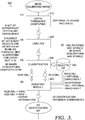
Figure 3 illustrates an exemplary process of an Intelligent Segmentation Engine (ISE), in an implementation of an embodiment of the invention; and -
Figure 4 illustrates an exemplary operational overview of combined 2D and 3D cameras for machine vision and identification, in an implementation of an embodiment of the invention. - The proposed apparatus and method can be used in automatic identification and machine vision applications, where there is the need for a low-cost solution without depth accuracy requirements mandatory in case of volume dimensioning or body scanning. Combining a
low cost 3D-TOF approach with a 2D high-resolution camera in a single package sensor together with an original machine learning segmentation method has some distinctive advantages: - Additional performance and speed-up for inspection and identification (barcode, optical character recognition (OCR)).
- Reduced total cost, size and weight for a 3D industrial camera
- Reduced computational load involved in 3D image processing (by mean of objects (OBJs) localization)
- Reduced memory needs to store 3D images (3D compression: relevant OBJs only)
- Reduced network bandwidth needs when a 3D image has to be transmitted
- Gesture recognition for self-shop applications, where high 3D accuracy is not required and the cost is a key-parameter
- Robotic barcode scanning
- Augmented Reality rendering: a framework for interactive AR applications, where the depth map is necessary for visual or physical interaction between synthetic and real, identified objects.
- An embodiment of the invention consists of a compact, single
package vision sensor 200 containing a standard high-resolution 2D camera 210 (brightness image) and alower resolution 3D camera 220 (depth image) pair, mounted and calibrated in an optical andgeometrical environment 230. The resulting, combinedcamera system 200, is a compact and portable device, with reduced 3D computational overload and power consumption. The combinedcamer system 200 includes a lighting system. - In a preferred embodiment,
system 200 will be shared by the twosensors 210 and 220 (both the sensors optimized for infrared (IR) range), butsystem 200 could also be composed of two different sensor types (IR-TOF sensor combined with 2D visible range sensor). Even if TOF cameras have less depth accuracy compared to other types of 3D sensors (e.g. laser scanners, structured light, or stereo vision systems), this is not a limitation for the intended purposes of the proposed invention, since it can benefit from the aid of a high-resolution 2D sensor. On the contrary, in respect to other 3D technologies, TOF cameras can be fitted to real-time applications where automatic acquisition of 3D models involves sensor movement. - To maximize the performance of the two-camera combination in
system 200, thecameras 3D TOF camera 220 be mounted on top of the2D camera 210. Moreover, the twosensors cameras camera 220 is mapped into the 2D image of camera 210 (a threshold can be applied to the depth image to discard background objects). A TOF sensor can be an industrial, entry level low-cost IR-based depth camera, with a low resolution (320x240 pixels or QVGA). - The
TOF camera 220 and the2D camera 210 are calibrated, and a mapping is made from the depth data to the 2D image. Calibration of 2D and 3D images is a state-of-the-art process, quite similar to a stereo camera calibration problem. It is only a matter of starting from 3D coordinates of theTOF camera 220 to find the corresponding 2D coordinates instead of building 3D coordinates from two sets of 2D coordinates. Given the calibrated image, segmentation will be performed directly on the depth image from theTOF camera 220, without using 2D information from the2D camera 210. This is a fundamental task for 3D vision, often the very first step. It consists of partitioning the corresponding digital image into groups of pixels (regions) with similar characteristics (e.g. color, intensity, texture, etc.) in order to simplify the detection and classification of objects in the scene. - Through segmentation, different objects in the scene are delimited by contours or segments consisting of boundaries such as lines and curves (closely related to edges). In addition, 3D image segmentation allows for subsequent 3D rendering of multiple objects and a quantitative analysis for their size, density and other parameters. Edges identified by edge detection are often disconnected while object segmentation needs closed region boundaries. There is no overlap between different regions and the union of all the segmented regions generates the entire image.
- Segmentation can also be applied to a stack of images (this is typical in medical imaging) so that the resulting contours can allow for 3D reconstructions through a kind of interpolation algorithm (e.g. Marching cubes). Many algorithms and techniques have been proposed for image segmentation, especially in the biomedical field. Particularly, the selected technique must be matched with the application's specific knowledge to get the best results.
- An important aspect of the invention is the custom Intelligent Segmentation Engine (ISE) 300 provided for the
system 200. It consists of five main components,depth threshold computing 310, labeling 320,classification 330,assistant module 340, and objects 350, designed to achieve automatic segmentation and classification while providing "expert information" to 2D algorithms. - A set of depth thresholds are computed (310) in order to extract labeled regions (e.g. foreground, background, etc.) from the depth image of
camera 220. It should be noted that a unique global threshold generally fails to detect all objects. Many known algorithms are available for this task. - For all the computed depth thresholds, some objects are extracted and labeled in 320.
- For all different extracted objects, the following processing steps are performed as part of
classification 330. - Robust 3D geometrical shape descriptors are computed in order to get a meaningful classification metric.
- Shape descriptors of the current object are compared to those in already available records stored in a local or remote data base. Based on this comparison, the current object can be said "new OBJ" (never seen before) or "old OBJ" (already seen before).
- An additional information called "reinforcement" is associated to every object in the data base. It is used as a weight factor in the previous comparison: objects with stronger reinforcement (i.e. more frequently classified) will be preferred in case of doubtful comparisons. It could also be possible to define a set of rules in order to better exploit this information to improve future object classifications.
- Classified objects can be either new objects or object already found in past images as determine in
assistant module 340. For both new and old OBJs, a set of specific 2D ROIs, corresponding to currently recognized 3D objects, are set as actual input for 2D algorithms. In case of "old OBJ", together with the ROIs, some additional "expert information" about the expected output identification or inspection can be supplied to the 2D algorithms to facilitate their operations. A ROI is typically defined as the borders of an object or the polygonal shape of an item in a 2D image. An example of the types of information discussed above is provided inTAB 1.TAB 1. EXPERT INFORMATIONROIS Regions of interest defined as one or more irregular 2D image sub-regions corresponding to one or more classified OBJs EXP_POS (old OBJ only) For every ROI, the expected (probable) location of all items already identified in previous object occurrences (past acquisitions). EXP_SIZE (old OBJ only) For every ROI, the expected (probable) size of all items already identified in previous object occurrences (past acquisitions). EXP_MODULE (old OBJ only) For every ROI, the expected (probable) barcode module (mm/mil) of all items already identified in previous object occurrences (past acquisitions). - Once the
AM 340 receives feedback from 2D algorithms (e.g. identified codes, inspection results), it will be able to: - Enrich the information associated to the objects with the current items identified (new or old objects), by increasing some counters corresponding to the "probabilities" referred in
TAB 1, to be stored with the object. - Store the objects in the database: from scratch if "new," updated with reinforcement if "old." Reinforcement consists of a counter to be increased after each new classification of the object.
- The
object database 350 can be viewed as a declarative memory referred to as general "world knowledge" accumulated through both 3D segmentation, 2D identification, and inspection experience. It is important to know "what an object is," not only to know that "an object exists." - Every OBJ record consists of some fields, as reported in
TAB 2, which precisely defines what the object is, what (items) is on its surface, and how much is common (hence, easy to find). - As an option: Additional information called "relations" can be associated to every object in the database (350) to detail its relation with other objects (inclusion, proximity, similarity, etc.). It could be used to facilitate the classification task.
TAB 2.OBJECT_ RECORD 3D SHAPE DESCRIPTORS May be a polygon mesh as a collection of vertices, edges and faces able to define the shape of a polyhedral object in 3D solid modeling (faces usually consist of triangles). ITEMS Identified patterns (barcodes, OCR text strings, inspection symbols) on the object, with related "expert information" (e.g. positions, sizes and modules). ENRICHMENT Number of times the items has been identified REINFORCEMENT Number of times the object has been classified - In
figure 4 , aconcept overview 400 is shown. An image 410 is captured withcameras - A very important point of the invention lies in its ability to enable real-time processing of actual complex scenes. Particularly, a brute force approach that uses high-
resolution 3D images (e.g. by stereo cameras or structured light) associated with high computational-load machine learning methods (e.g. deep convolutional neural networks, Bayesian networks, etc.) would probably require more processing time and specific hardware resources (such as dedicated GPUs) that are not compatible with the invention, in low cost automatic identification and machine vision applications. - More specifically, embodiments of the invention use the following elements in a compact package:
- Since the depth image involves a small number of data points (e.g. 320×240 pixels, QVGA), computing depth thresholds to extract labeled regions and computing raw shape descriptors (there is no need to model any object detail) can be considered a low computational-load task, feasible in the embedded environment.
- The maximum benefits in terms of processing time can be achieved when using a high-
resolution 2D imager (e.g. sensors with more than 5 megapixels). This is because alow resolution 3D camera effectively filter information to 2D algorithms. - Instead of a huge machine learning method, collected EXPERT_INFORMATION is used to be linked with OBJECT_RECORDs that can be managed by means of simple row/column tables. In other words, the most "reinforced" objects will be the first to be searched during the classification phase (and it will be first searched in the most likely positions).
- A further processing time saving is due to the fact that 2D identification and machine vision algorithms can take advantage of EXPERT_INFORMATION to analyze first (or even exclusively) the region of image associated with the segmented 3D object. In addition, the algorithm parameters can be automatically adjusted over that region in agreement with the expected items that will most likely be found (this information is stored as "enrichment").
- Many different arrangements of the various components depicted, as well as components not shown, are possible without departing from the scope of the claims below. Embodiments of our technology have been described with the intent to be illustrative rather than restrictive. Alternative embodiments will become apparent to readers of this disclosure after and because of reading it. Alternative means of implementing the aforementioned invention can be completed without departing from the scope of the claims below. Certain features and subcombinations are of utility and may be employed without reference to other features and subcombinations and are contemplated within the scope of the claims.
Claims (14)
- A method of object recognition in a hybrid 2D/3D vision system, comprising:acquiring a three-dimensional image of an object into a vision device, wherein the vision device has a processor coupled to a memory;acquiring one or more two-dimensional images of the object into the vision device, wherein the three-dimensional image is associated with the one or more two-dimensional images;identifying the three-dimensional image through three-dimensional shape recognition, wherein identifying the three-dimensional image comprises comparing one or more shapes in the three-dimensional image to objects in a database, and wherein a union of the one or more shapes generates the three-dimensional image;if a member of the one or more shapes of the three-dimensional image matches to one of the objects in the database, matching the one of the objects to a region of interest from the one or more two-dimensional images;simultaneously, analyzing the member of the one or more shapes of the three-dimensional image that matches to the one of the objects and the region of interest from the one or more two-dimensional images to speed up an object recognition process; anddetecting a new region of interest from the one or more two-dimensional images if another member of the one or more shapes of the three-dimensional image does not match to another one of the objects in the database, wherein the new region of interest matches to another member of the one or more shapes of the three-dimensional image.
- The method of claim 1, wherein the new region of interest is stored in the database or another database.
- The method of claim 1, wherein the step of identifying comprises:computing shape descriptors for the object;comparing the shape descriptors for the object to other shape descriptors that are stored in the database;if a shape descriptor of the object matches one of the other shape descriptors in the database, designating the object as an old object that is already in the database, wherein the object matches the old object in the database;if the shape descriptor of the object does not match one of the other shape descriptors in the database, designating the object as a new object and storing the object in the database;where the object matches the old object in the database, assigning a weight factor or reinforcement to the object;increasing the weight factor or reinforcement of the object each time the shape descriptor of the object is used in a comparison and matches to the one of the other shape descriptors, wherein the object that is more frequently classified has a stronger reinforcement; andfor a comparison that is not sufficient, using the object that has a strongest reinforcement over other objects in the database with lesser reinforcements.
- The method of claim 3, further comprising increasing a counter at the object whenever the shape descriptor of the object is compared and matched to the one of the other shape descriptors in the database, wherein a highest value of the counter of the object indicates the strongest reinforcement over the other objects in the database with a lower value of the counter.
- The method of claim 3, further comprising updating the object upon a subsequent comparison and the object is already in the database designated as the old object or the new object.
- The method of claim 3, wherein the shape descriptors are the contours or shapes of items that are described.
- The method of claim 1, wherein the step of identifying comprises:computing shape descriptors for the object;comparing the shape descriptors for the object to other shape descriptors that are stored in the database;if a shape descriptor of the object matches one of the other shape descriptors in the database, designating the object as an old object that is already in the database, wherein the object matches the old object in the database;if the shape descriptor of the object does not match one of the other shape descriptors in the database, designating the object as a new object and storing the object in the database.
- The method of any previous claims, further comprising applying a threshold to the 3D image to discard background objects in the 3D image.
- A compact and portable device, comprising:a high-resolution two-dimensional (2D) camera;a low-resolution three-dimensional (3D) camera;a lighting system shared by the 2D camera and 3D camera;the 2D camera and 3D camera mounted together to have parallel optical axes, wherein a first sensor of the 2D camera and a second sensor of the 3D camera point in a same direction and have similar viewing areas, wherein the 3D camera is mounted on top of the 2D camera;the first sensor and the second sensor simultaneously capture a 2D image and 3D image of a same viewing area;the 3D image is mapped into the 2D image to form a composite image.
- The device of claim 9, wherein the low-resolution 3D camera has reduced 3D computational overload and power consumption.
- The device of claim 9, wherein the high-resolution 2D camera and the low-resolution 3D camera have sensors optimized for the infrared (IR) range.
- The device of claim 9, wherein the high-resolution 2D camera has a sensor optimized for the visible range and the low-resolution 3D camera have a sensor optimized for the infrared (IR) range.
- The device of claim 9, wherein the high-resolution 2D camera and the low-resolution 2D camera simultaneously frame-grab an image.
- The device of claim 13, wherein a 3D Time of Flight (TOF) image from the low-resolution 3D camera is mapped into the 2D image from the high-resolution 2D camera.
Applications Claiming Priority (1)
| Application Number | Priority Date | Filing Date | Title |
|---|---|---|---|
| US15/845,695 US10558844B2 (en) | 2017-12-18 | 2017-12-18 | Lightweight 3D vision camera with intelligent segmentation engine for machine vision and auto identification |
Publications (2)
| Publication Number | Publication Date |
|---|---|
| EP3499414A1 true EP3499414A1 (en) | 2019-06-19 |
| EP3499414B1 EP3499414B1 (en) | 2024-02-07 |
Family
ID=64744492
Family Applications (1)
| Application Number | Title | Priority Date | Filing Date |
|---|---|---|---|
| EP18213164.9A Active EP3499414B1 (en) | 2017-12-18 | 2018-12-17 | Lightweight 3d vision camera with intelligent segmentation engine for machine vision and auto identification |
Country Status (2)
| Country | Link |
|---|---|
| US (1) | US10558844B2 (en) |
| EP (1) | EP3499414B1 (en) |
Cited By (1)
| Publication number | Priority date | Publication date | Assignee | Title |
|---|---|---|---|---|
| US12561937B2 (en) * | 2022-08-17 | 2026-02-24 | Bull Sas | Method, computer program, profile identification device |
Families Citing this family (16)
| Publication number | Priority date | Publication date | Assignee | Title |
|---|---|---|---|---|
| JP6333871B2 (en) * | 2016-02-25 | 2018-05-30 | ファナック株式会社 | Image processing apparatus for displaying an object detected from an input image |
| EP3565259A4 (en) * | 2016-12-28 | 2019-11-06 | Panasonic Intellectual Property Corporation of America | THREE-DIMENSIONAL MODEL DISTRIBUTION METHOD, THREE-DIMENSIONAL MODEL RECEIVING METHOD, THREE-DIMENSIONAL MODEL DISTRIBUTION DEVICE, AND THREE-DIMENSIONAL MODEL RECEIVING DEVICE |
| US10846561B1 (en) | 2020-04-01 | 2020-11-24 | Scandit Ag | Recognition and selection of discrete patterns within a scene or image |
| US11514665B2 (en) | 2020-04-01 | 2022-11-29 | Scandit Ag | Mapping optical-code images to an overview image |
| US11295163B1 (en) | 2020-04-01 | 2022-04-05 | Scandit Ag | Recognition of optical patterns in images acquired by a robotic device |
| US20210319619A1 (en) * | 2020-04-08 | 2021-10-14 | The Boeing Company | Method for Ergonomic Scoring From Webcam |
| WO2021212420A1 (en) * | 2020-04-23 | 2021-10-28 | Nokia Technologies Oy | Method and device for 3d object detection |
| US11403477B1 (en) | 2020-05-15 | 2022-08-02 | Scandit Ag | Image exposure performance improvements for recognition of optical patterns |
| US11334739B2 (en) * | 2020-05-29 | 2022-05-17 | Zebra Technologies Corporation | Barcode readers with 3D camera(s) |
| US12488473B1 (en) | 2020-07-27 | 2025-12-02 | Scandit Ag | Multi-barcode detection in a real scene using interface enhancement based on user input |
| US11880738B1 (en) | 2021-08-17 | 2024-01-23 | Scandit Ag | Visual odometry for optical pattern scanning in a real scene |
| US11602132B2 (en) | 2020-10-06 | 2023-03-14 | Sixgill, LLC | System and method of counting livestock |
| US12175327B1 (en) | 2020-12-04 | 2024-12-24 | Scandit Ag | Camera start optimization for optical pattern decoding |
| US11495036B1 (en) * | 2021-01-29 | 2022-11-08 | Scandit Ag | Segmenting images for optical character recognition |
| JP2023038048A (en) * | 2021-09-06 | 2023-03-16 | ソニーセミコンダクタソリューションズ株式会社 | Operation detection device, information processing system, and operation detection method |
| CN116934308B (en) * | 2023-09-15 | 2023-12-15 | 浙江恒逸石化有限公司 | Control method, device and equipment of road inspection equipment and storage medium |
Citations (2)
| Publication number | Priority date | Publication date | Assignee | Title |
|---|---|---|---|---|
| CN103033145A (en) * | 2013-01-08 | 2013-04-10 | 天津锋时互动科技有限公司 | Method and system for identifying shapes of plurality of objects |
| WO2016167947A1 (en) * | 2015-04-14 | 2016-10-20 | Microsoft Technology Licensing, Llc | Two-dimensional infrared depth sensing |
Family Cites Families (41)
| Publication number | Priority date | Publication date | Assignee | Title |
|---|---|---|---|---|
| US6002782A (en) * | 1997-11-12 | 1999-12-14 | Unisys Corporation | System and method for recognizing a 3-D object by generating a 2-D image of the object from a transformed 3-D model |
| US6792401B1 (en) * | 2000-10-31 | 2004-09-14 | Diamond Visionics Company | Internet-based modeling kiosk and method for fitting and selling prescription eyeglasses |
| US7197165B2 (en) * | 2002-02-04 | 2007-03-27 | Canon Kabushiki Kaisha | Eye tracking using image data |
| JP2004164503A (en) * | 2002-11-15 | 2004-06-10 | Olympus Corp | Three-dimensional model search method, three-dimensional model search device, three-dimensional model search program, and three-dimensional model search system |
| CN100495187C (en) * | 2004-04-03 | 2009-06-03 | 孙犁 | Dual polarizing light filter for 2-D and 3-D display |
| US7609865B2 (en) * | 2004-11-08 | 2009-10-27 | Biomagnetics | 3D fingerprint and palm print data model and capture devices using multi structured lights and cameras |
| US8396329B2 (en) * | 2004-12-23 | 2013-03-12 | General Electric Company | System and method for object measurement |
| US7551807B2 (en) * | 2005-11-14 | 2009-06-23 | Korea Institute Of Industrial Technology | Apparatus and method for searching for 3-dimensional shapes |
| IL196162A (en) * | 2008-12-24 | 2013-02-28 | Rafael Advanced Defense Sys | System for using three-dimensional models to enable image comparisons independent of image source |
| US8743176B2 (en) * | 2009-05-20 | 2014-06-03 | Advanced Scientific Concepts, Inc. | 3-dimensional hybrid camera and production system |
| US7929852B1 (en) * | 2009-10-13 | 2011-04-19 | Vincent Pace | Integrated 2D/3D camera |
| US8363156B2 (en) * | 2010-04-09 | 2013-01-29 | 3Dv Co. Ltd | Single-lens 2D/3D digital camera |
| WO2011156474A2 (en) * | 2010-06-10 | 2011-12-15 | Brown University | Parameterized model of 2d articulated human shape |
| WO2012040827A2 (en) * | 2010-10-01 | 2012-04-05 | Smart Technologies Ulc | Interactive input system having a 3d input space |
| US8879902B2 (en) * | 2010-10-08 | 2014-11-04 | Vincent Pace & James Cameron | Integrated 2D/3D camera with fixed imaging parameters |
| WO2012124686A1 (en) * | 2011-03-14 | 2012-09-20 | Hoshino Kiyoshi | Nail region detection method, program, storage medium, and nail region detection device |
| KR101804848B1 (en) * | 2011-04-22 | 2017-12-06 | 삼성전자주식회사 | Video Object Detecting Apparatus, Video Object Deforming Apparatus and Method thereof |
| US20120289836A1 (en) * | 2011-05-12 | 2012-11-15 | Osamu Ukimura | Automatic real-time display system for the orientation and location of an ultrasound tomogram in a three-dimensional organ model |
| GB201115265D0 (en) * | 2011-09-05 | 2011-10-19 | Materialise Dental Nv | A method and system for 3d root canal treatment planning |
| US9069075B2 (en) * | 2012-02-10 | 2015-06-30 | GM Global Technology Operations LLC | Coupled range and intensity imaging for motion estimation |
| US8655163B2 (en) * | 2012-02-13 | 2014-02-18 | Cameron Pace Group Llc | Consolidated 2D/3D camera |
| US10848731B2 (en) * | 2012-02-24 | 2020-11-24 | Matterport, Inc. | Capturing and aligning panoramic image and depth data |
| JP2015184054A (en) * | 2014-03-20 | 2015-10-22 | 株式会社東芝 | Identification apparatus, method and program |
| EP2983131A1 (en) * | 2014-08-06 | 2016-02-10 | Thomson Licensing | Method and device for camera calibration |
| US20170308736A1 (en) * | 2014-10-28 | 2017-10-26 | Hewlett-Packard Development Company, L.P. | Three dimensional object recognition |
| CN107873101B (en) * | 2014-11-21 | 2022-01-11 | 克里斯多夫·M·马蒂 | Imaging system for object recognition and evaluation |
| US20160183057A1 (en) * | 2014-12-18 | 2016-06-23 | Intel Corporation | Method and system for hybrid location detection |
| US9801517B2 (en) * | 2015-03-06 | 2017-10-31 | Wal-Mart Stores, Inc. | Shopping facility assistance object detection systems, devices and methods |
| CA2979836C (en) * | 2015-03-17 | 2023-08-29 | Cornell University | Depth field imaging apparatus, methods, and applications |
| ITUB20154043A1 (en) | 2015-09-30 | 2017-03-30 | Datalogic IP Tech Srl | System and method of reading encoded information |
| WO2017078777A1 (en) * | 2015-11-04 | 2017-05-11 | Intel Corporation | Generating voxel representations and assigning trust metrics for ensuring veracity for use with multiple applications |
| JP6606985B2 (en) * | 2015-11-06 | 2019-11-20 | 富士通株式会社 | Image processing method, image processing program, and image processing apparatus |
| US9727775B2 (en) * | 2015-12-01 | 2017-08-08 | Intel Corporation | Method and system of curved object recognition using image matching for image processing |
| US9491444B2 (en) * | 2016-05-27 | 2016-11-08 | Kedrick F. Brown | Auto-multiscopic 3D display system |
| US10482621B2 (en) * | 2016-08-01 | 2019-11-19 | Cognex Corporation | System and method for improved scoring of 3D poses and spurious point removal in 3D image data |
| US20180053247A1 (en) * | 2016-08-19 | 2018-02-22 | Wal-Mart Stores, Inc. | Produce selection system for bulk items |
| GB201614492D0 (en) * | 2016-08-25 | 2016-10-12 | Rolls Royce Plc | Methods, apparatus, computer programs, and non-transitory computer readable storage mediums for processing data from a sensor |
| US10235771B2 (en) * | 2016-11-11 | 2019-03-19 | Qualcomm Incorporated | Methods and systems of performing object pose estimation |
| US10055880B2 (en) * | 2016-12-06 | 2018-08-21 | Activision Publishing, Inc. | Methods and systems to modify a two dimensional facial image to increase dimensional depth and generate a facial image that appears three dimensional |
| JP6657132B2 (en) * | 2017-02-27 | 2020-03-04 | 富士フイルム株式会社 | Image classification device, method and program |
| US10430641B2 (en) * | 2017-03-08 | 2019-10-01 | GM Global Technology Operations LLC | Methods and systems for object tracking using bounding boxes |
-
2017
- 2017-12-18 US US15/845,695 patent/US10558844B2/en active Active
-
2018
- 2018-12-17 EP EP18213164.9A patent/EP3499414B1/en active Active
Patent Citations (2)
| Publication number | Priority date | Publication date | Assignee | Title |
|---|---|---|---|---|
| CN103033145A (en) * | 2013-01-08 | 2013-04-10 | 天津锋时互动科技有限公司 | Method and system for identifying shapes of plurality of objects |
| WO2016167947A1 (en) * | 2015-04-14 | 2016-10-20 | Microsoft Technology Licensing, Llc | Two-dimensional infrared depth sensing |
Cited By (1)
| Publication number | Priority date | Publication date | Assignee | Title |
|---|---|---|---|---|
| US12561937B2 (en) * | 2022-08-17 | 2026-02-24 | Bull Sas | Method, computer program, profile identification device |
Also Published As
| Publication number | Publication date |
|---|---|
| US10558844B2 (en) | 2020-02-11 |
| US20190188451A1 (en) | 2019-06-20 |
| EP3499414B1 (en) | 2024-02-07 |
Similar Documents
| Publication | Publication Date | Title |
|---|---|---|
| EP3499414B1 (en) | Lightweight 3d vision camera with intelligent segmentation engine for machine vision and auto identification | |
| US10691979B2 (en) | Systems and methods for shape-based object retrieval | |
| Sodhi et al. | In-field segmentation and identification of plant structures using 3D imaging | |
| US9934591B2 (en) | Remote determination of quantity stored in containers in geographical region | |
| CN108734087B (en) | Object automatic identification method and system, shopping device and storage medium | |
| Benedek | 3D people surveillance on range data sequences of a rotating Lidar | |
| CN103093191A (en) | Object recognition method with three-dimensional point cloud data and digital image data combined | |
| CN115861352B (en) | Data fusion and edge extraction method for monocular vision, IMU and laser radar | |
| Kim et al. | Building detection in high resolution remotely sensed images based on automatic histogram-based fuzzy c-means algorithm | |
| CN112016495A (en) | Face recognition method and device and electronic equipment | |
| Ao et al. | Fully convolutional networks for street furniture identification in panorama images | |
| US20240412412A1 (en) | Segmentation based visual simultaneous localization and mapping (slam) | |
| CN110796688A (en) | Multi-target face recognition intelligent flight information display method and system | |
| CN121415374A (en) | A method and system for constructing a robot memory bank | |
| Budzan | Fusion of visual and range images for object extraction | |
| CN117928540A (en) | Positioning method and positioning device for robot, and storage medium | |
| Wang et al. | Performance study of feature descriptors for human detection on depth map | |
| Li et al. | Pedestrian detection algorithm based on video sequences and laser point cloud | |
| Zhou et al. | Design of automatic target recognition and detection system for sensors based on improved machine vision control | |
| Nguyen et al. | Application of graph segmentation method in thermal camera object detection | |
| Hanten et al. | Robust real-time 3d person detection for indoor and outdoor applications | |
| Wu et al. | An effective method for human detection using far-infrared images | |
| KALAMPUKATT et al. | Integrating Object Detection and Distance Estimation: A Comprehensive Review of Techniques and Applications | |
| Sato et al. | Performance comparison of semantic segmentation models and loss functions for seat belt detection | |
| Johansson et al. | Evaluation of monocular visual SLAM methods on UAV imagery to reconstruct 3D terrain |
Legal Events
| Date | Code | Title | Description |
|---|---|---|---|
| PUAI | Public reference made under article 153(3) epc to a published international application that has entered the european phase |
Free format text: ORIGINAL CODE: 0009012 |
|
| STAA | Information on the status of an ep patent application or granted ep patent |
Free format text: STATUS: THE APPLICATION HAS BEEN PUBLISHED |
|
| AK | Designated contracting states |
Kind code of ref document: A1 Designated state(s): AL AT BE BG CH CY CZ DE DK EE ES FI FR GB GR HR HU IE IS IT LI LT LU LV MC MK MT NL NO PL PT RO RS SE SI SK SM TR |
|
| AX | Request for extension of the european patent |
Extension state: BA ME |
|
| STAA | Information on the status of an ep patent application or granted ep patent |
Free format text: STATUS: REQUEST FOR EXAMINATION WAS MADE |
|
| 17P | Request for examination filed |
Effective date: 20191212 |
|
| RBV | Designated contracting states (corrected) |
Designated state(s): AL AT BE BG CH CY CZ DE DK EE ES FI FR GB GR HR HU IE IS IT LI LT LU LV MC MK MT NL NO PL PT RO RS SE SI SK SM TR |
|
| STAA | Information on the status of an ep patent application or granted ep patent |
Free format text: STATUS: EXAMINATION IS IN PROGRESS |
|
| 17Q | First examination report despatched |
Effective date: 20210623 |
|
| REG | Reference to a national code |
Ref legal event code: R079 Ref country code: DE Ref legal event code: R079 Ref document number: 602018064909 Country of ref document: DE Free format text: PREVIOUS MAIN CLASS: G06K0009000000 Ipc: G06V0020640000 |
|
| RIC1 | Information provided on ipc code assigned before grant |
Ipc: G06V 10/25 20220101ALI20230322BHEP Ipc: G06V 10/46 20220101ALI20230322BHEP Ipc: G06V 10/422 20220101ALI20230322BHEP Ipc: G06V 20/64 20220101AFI20230322BHEP |
|
| GRAP | Despatch of communication of intention to grant a patent |
Free format text: ORIGINAL CODE: EPIDOSNIGR1 |
|
| STAA | Information on the status of an ep patent application or granted ep patent |
Free format text: STATUS: GRANT OF PATENT IS INTENDED |
|
| INTG | Intention to grant announced |
Effective date: 20230428 |
|
| P01 | Opt-out of the competence of the unified patent court (upc) registered |
Effective date: 20230527 |
|
| GRAJ | Information related to disapproval of communication of intention to grant by the applicant or resumption of examination proceedings by the epo deleted |
Free format text: ORIGINAL CODE: EPIDOSDIGR1 |
|
| STAA | Information on the status of an ep patent application or granted ep patent |
Free format text: STATUS: EXAMINATION IS IN PROGRESS |
|
| GRAP | Despatch of communication of intention to grant a patent |
Free format text: ORIGINAL CODE: EPIDOSNIGR1 |
|
| STAA | Information on the status of an ep patent application or granted ep patent |
Free format text: STATUS: GRANT OF PATENT IS INTENDED |
|
| INTC | Intention to grant announced (deleted) | ||
| INTG | Intention to grant announced |
Effective date: 20230823 |
|
| GRAS | Grant fee paid |
Free format text: ORIGINAL CODE: EPIDOSNIGR3 |
|
| GRAA | (expected) grant |
Free format text: ORIGINAL CODE: 0009210 |
|
| STAA | Information on the status of an ep patent application or granted ep patent |
Free format text: STATUS: THE PATENT HAS BEEN GRANTED |
|
| AK | Designated contracting states |
Kind code of ref document: B1 Designated state(s): AL AT BE BG CH CY CZ DE DK EE ES FI FR GB GR HR HU IE IS IT LI LT LU LV MC MK MT NL NO PL PT RO RS SE SI SK SM TR |
|
| REG | Reference to a national code |
Ref country code: GB Ref legal event code: FG4D |
|
| REG | Reference to a national code |
Ref country code: CH Ref legal event code: EP |
|
| REG | Reference to a national code |
Ref country code: IE Ref legal event code: FG4D |
|
| REG | Reference to a national code |
Ref country code: DE Ref legal event code: R096 Ref document number: 602018064909 Country of ref document: DE |
|
| REG | Reference to a national code |
Ref country code: LT Ref legal event code: MG9D |
|
| REG | Reference to a national code |
Ref country code: NL Ref legal event code: MP Effective date: 20240207 |
|
| PG25 | Lapsed in a contracting state [announced via postgrant information from national office to epo] |
Ref country code: IS Free format text: LAPSE BECAUSE OF FAILURE TO SUBMIT A TRANSLATION OF THE DESCRIPTION OR TO PAY THE FEE WITHIN THE PRESCRIBED TIME-LIMIT Effective date: 20240607 |
|
| PG25 | Lapsed in a contracting state [announced via postgrant information from national office to epo] |
Ref country code: LT Free format text: LAPSE BECAUSE OF FAILURE TO SUBMIT A TRANSLATION OF THE DESCRIPTION OR TO PAY THE FEE WITHIN THE PRESCRIBED TIME-LIMIT Effective date: 20240207 |
|
| PG25 | Lapsed in a contracting state [announced via postgrant information from national office to epo] |
Ref country code: GR Free format text: LAPSE BECAUSE OF FAILURE TO SUBMIT A TRANSLATION OF THE DESCRIPTION OR TO PAY THE FEE WITHIN THE PRESCRIBED TIME-LIMIT Effective date: 20240508 |
|
| REG | Reference to a national code |
Ref country code: AT Ref legal event code: MK05 Ref document number: 1655847 Country of ref document: AT Kind code of ref document: T Effective date: 20240207 |
|
| PG25 | Lapsed in a contracting state [announced via postgrant information from national office to epo] |
Ref country code: RS Free format text: LAPSE BECAUSE OF FAILURE TO SUBMIT A TRANSLATION OF THE DESCRIPTION OR TO PAY THE FEE WITHIN THE PRESCRIBED TIME-LIMIT Effective date: 20240507 Ref country code: HR Free format text: LAPSE BECAUSE OF FAILURE TO SUBMIT A TRANSLATION OF THE DESCRIPTION OR TO PAY THE FEE WITHIN THE PRESCRIBED TIME-LIMIT Effective date: 20240207 Ref country code: NL Free format text: LAPSE BECAUSE OF FAILURE TO SUBMIT A TRANSLATION OF THE DESCRIPTION OR TO PAY THE FEE WITHIN THE PRESCRIBED TIME-LIMIT Effective date: 20240207 |
|
| PG25 | Lapsed in a contracting state [announced via postgrant information from national office to epo] |
Ref country code: ES Free format text: LAPSE BECAUSE OF FAILURE TO SUBMIT A TRANSLATION OF THE DESCRIPTION OR TO PAY THE FEE WITHIN THE PRESCRIBED TIME-LIMIT Effective date: 20240207 |
|
| PG25 | Lapsed in a contracting state [announced via postgrant information from national office to epo] |
Ref country code: AT Free format text: LAPSE BECAUSE OF FAILURE TO SUBMIT A TRANSLATION OF THE DESCRIPTION OR TO PAY THE FEE WITHIN THE PRESCRIBED TIME-LIMIT Effective date: 20240207 |
|
| PG25 | Lapsed in a contracting state [announced via postgrant information from national office to epo] |
Ref country code: RS Free format text: LAPSE BECAUSE OF FAILURE TO SUBMIT A TRANSLATION OF THE DESCRIPTION OR TO PAY THE FEE WITHIN THE PRESCRIBED TIME-LIMIT Effective date: 20240507 Ref country code: NO Free format text: LAPSE BECAUSE OF FAILURE TO SUBMIT A TRANSLATION OF THE DESCRIPTION OR TO PAY THE FEE WITHIN THE PRESCRIBED TIME-LIMIT Effective date: 20240507 Ref country code: NL Free format text: LAPSE BECAUSE OF FAILURE TO SUBMIT A TRANSLATION OF THE DESCRIPTION OR TO PAY THE FEE WITHIN THE PRESCRIBED TIME-LIMIT Effective date: 20240207 Ref country code: LT Free format text: LAPSE BECAUSE OF FAILURE TO SUBMIT A TRANSLATION OF THE DESCRIPTION OR TO PAY THE FEE WITHIN THE PRESCRIBED TIME-LIMIT Effective date: 20240207 Ref country code: IS Free format text: LAPSE BECAUSE OF FAILURE TO SUBMIT A TRANSLATION OF THE DESCRIPTION OR TO PAY THE FEE WITHIN THE PRESCRIBED TIME-LIMIT Effective date: 20240607 Ref country code: HR Free format text: LAPSE BECAUSE OF FAILURE TO SUBMIT A TRANSLATION OF THE DESCRIPTION OR TO PAY THE FEE WITHIN THE PRESCRIBED TIME-LIMIT Effective date: 20240207 Ref country code: GR Free format text: LAPSE BECAUSE OF FAILURE TO SUBMIT A TRANSLATION OF THE DESCRIPTION OR TO PAY THE FEE WITHIN THE PRESCRIBED TIME-LIMIT Effective date: 20240508 Ref country code: FI Free format text: LAPSE BECAUSE OF FAILURE TO SUBMIT A TRANSLATION OF THE DESCRIPTION OR TO PAY THE FEE WITHIN THE PRESCRIBED TIME-LIMIT Effective date: 20240207 Ref country code: ES Free format text: LAPSE BECAUSE OF FAILURE TO SUBMIT A TRANSLATION OF THE DESCRIPTION OR TO PAY THE FEE WITHIN THE PRESCRIBED TIME-LIMIT Effective date: 20240207 Ref country code: BG Free format text: LAPSE BECAUSE OF FAILURE TO SUBMIT A TRANSLATION OF THE DESCRIPTION OR TO PAY THE FEE WITHIN THE PRESCRIBED TIME-LIMIT Effective date: 20240207 Ref country code: AT Free format text: LAPSE BECAUSE OF FAILURE TO SUBMIT A TRANSLATION OF THE DESCRIPTION OR TO PAY THE FEE WITHIN THE PRESCRIBED TIME-LIMIT Effective date: 20240207 |
|
| PG25 | Lapsed in a contracting state [announced via postgrant information from national office to epo] |
Ref country code: PT Free format text: LAPSE BECAUSE OF FAILURE TO SUBMIT A TRANSLATION OF THE DESCRIPTION OR TO PAY THE FEE WITHIN THE PRESCRIBED TIME-LIMIT Effective date: 20240607 Ref country code: PL Free format text: LAPSE BECAUSE OF FAILURE TO SUBMIT A TRANSLATION OF THE DESCRIPTION OR TO PAY THE FEE WITHIN THE PRESCRIBED TIME-LIMIT Effective date: 20240207 |
|
| PG25 | Lapsed in a contracting state [announced via postgrant information from national office to epo] |
Ref country code: SE Free format text: LAPSE BECAUSE OF FAILURE TO SUBMIT A TRANSLATION OF THE DESCRIPTION OR TO PAY THE FEE WITHIN THE PRESCRIBED TIME-LIMIT Effective date: 20240207 Ref country code: PT Free format text: LAPSE BECAUSE OF FAILURE TO SUBMIT A TRANSLATION OF THE DESCRIPTION OR TO PAY THE FEE WITHIN THE PRESCRIBED TIME-LIMIT Effective date: 20240607 Ref country code: PL Free format text: LAPSE BECAUSE OF FAILURE TO SUBMIT A TRANSLATION OF THE DESCRIPTION OR TO PAY THE FEE WITHIN THE PRESCRIBED TIME-LIMIT Effective date: 20240207 Ref country code: LV Free format text: LAPSE BECAUSE OF FAILURE TO SUBMIT A TRANSLATION OF THE DESCRIPTION OR TO PAY THE FEE WITHIN THE PRESCRIBED TIME-LIMIT Effective date: 20240207 |
|
| PG25 | Lapsed in a contracting state [announced via postgrant information from national office to epo] |
Ref country code: DK Free format text: LAPSE BECAUSE OF FAILURE TO SUBMIT A TRANSLATION OF THE DESCRIPTION OR TO PAY THE FEE WITHIN THE PRESCRIBED TIME-LIMIT Effective date: 20240207 |
|
| PG25 | Lapsed in a contracting state [announced via postgrant information from national office to epo] |
Ref country code: SM Free format text: LAPSE BECAUSE OF FAILURE TO SUBMIT A TRANSLATION OF THE DESCRIPTION OR TO PAY THE FEE WITHIN THE PRESCRIBED TIME-LIMIT Effective date: 20240207 |
|
| PG25 | Lapsed in a contracting state [announced via postgrant information from national office to epo] |
Ref country code: CZ Free format text: LAPSE BECAUSE OF FAILURE TO SUBMIT A TRANSLATION OF THE DESCRIPTION OR TO PAY THE FEE WITHIN THE PRESCRIBED TIME-LIMIT Effective date: 20240207 Ref country code: EE Free format text: LAPSE BECAUSE OF FAILURE TO SUBMIT A TRANSLATION OF THE DESCRIPTION OR TO PAY THE FEE WITHIN THE PRESCRIBED TIME-LIMIT Effective date: 20240207 |
|
| PG25 | Lapsed in a contracting state [announced via postgrant information from national office to epo] |
Ref country code: SK Free format text: LAPSE BECAUSE OF FAILURE TO SUBMIT A TRANSLATION OF THE DESCRIPTION OR TO PAY THE FEE WITHIN THE PRESCRIBED TIME-LIMIT Effective date: 20240207 |
|
| PG25 | Lapsed in a contracting state [announced via postgrant information from national office to epo] |
Ref country code: SM Free format text: LAPSE BECAUSE OF FAILURE TO SUBMIT A TRANSLATION OF THE DESCRIPTION OR TO PAY THE FEE WITHIN THE PRESCRIBED TIME-LIMIT Effective date: 20240207 Ref country code: SK Free format text: LAPSE BECAUSE OF FAILURE TO SUBMIT A TRANSLATION OF THE DESCRIPTION OR TO PAY THE FEE WITHIN THE PRESCRIBED TIME-LIMIT Effective date: 20240207 Ref country code: RO Free format text: LAPSE BECAUSE OF FAILURE TO SUBMIT A TRANSLATION OF THE DESCRIPTION OR TO PAY THE FEE WITHIN THE PRESCRIBED TIME-LIMIT Effective date: 20240207 Ref country code: EE Free format text: LAPSE BECAUSE OF FAILURE TO SUBMIT A TRANSLATION OF THE DESCRIPTION OR TO PAY THE FEE WITHIN THE PRESCRIBED TIME-LIMIT Effective date: 20240207 Ref country code: DK Free format text: LAPSE BECAUSE OF FAILURE TO SUBMIT A TRANSLATION OF THE DESCRIPTION OR TO PAY THE FEE WITHIN THE PRESCRIBED TIME-LIMIT Effective date: 20240207 Ref country code: CZ Free format text: LAPSE BECAUSE OF FAILURE TO SUBMIT A TRANSLATION OF THE DESCRIPTION OR TO PAY THE FEE WITHIN THE PRESCRIBED TIME-LIMIT Effective date: 20240207 |
|
| REG | Reference to a national code |
Ref country code: DE Ref legal event code: R097 Ref document number: 602018064909 Country of ref document: DE |
|
| PLBE | No opposition filed within time limit |
Free format text: ORIGINAL CODE: 0009261 |
|
| STAA | Information on the status of an ep patent application or granted ep patent |
Free format text: STATUS: NO OPPOSITION FILED WITHIN TIME LIMIT |
|
| 26N | No opposition filed |
Effective date: 20241108 |
|
| PG25 | Lapsed in a contracting state [announced via postgrant information from national office to epo] |
Ref country code: SI Free format text: LAPSE BECAUSE OF FAILURE TO SUBMIT A TRANSLATION OF THE DESCRIPTION OR TO PAY THE FEE WITHIN THE PRESCRIBED TIME-LIMIT Effective date: 20240207 |
|
| PG25 | Lapsed in a contracting state [announced via postgrant information from national office to epo] |
Ref country code: MC Free format text: LAPSE BECAUSE OF FAILURE TO SUBMIT A TRANSLATION OF THE DESCRIPTION OR TO PAY THE FEE WITHIN THE PRESCRIBED TIME-LIMIT Effective date: 20240207 |
|
| REG | Reference to a national code |
Ref country code: CH Ref legal event code: PL |
|
| PG25 | Lapsed in a contracting state [announced via postgrant information from national office to epo] |
Ref country code: LU Free format text: LAPSE BECAUSE OF NON-PAYMENT OF DUE FEES Effective date: 20241217 |
|
| GBPC | Gb: european patent ceased through non-payment of renewal fee |
Effective date: 20241217 |
|
| REG | Reference to a national code |
Ref country code: BE Ref legal event code: MM Effective date: 20241231 |
|
| PG25 | Lapsed in a contracting state [announced via postgrant information from national office to epo] |
Ref country code: GB Free format text: LAPSE BECAUSE OF NON-PAYMENT OF DUE FEES Effective date: 20241217 Ref country code: BE Free format text: LAPSE BECAUSE OF NON-PAYMENT OF DUE FEES Effective date: 20241231 |
|
| PG25 | Lapsed in a contracting state [announced via postgrant information from national office to epo] |
Ref country code: CH Free format text: LAPSE BECAUSE OF NON-PAYMENT OF DUE FEES Effective date: 20241231 |
|
| PG25 | Lapsed in a contracting state [announced via postgrant information from national office to epo] |
Ref country code: IE Free format text: LAPSE BECAUSE OF NON-PAYMENT OF DUE FEES Effective date: 20241217 |
|
| PGFP | Annual fee paid to national office [announced via postgrant information from national office to epo] |
Ref country code: DE Payment date: 20251211 Year of fee payment: 8 |
|
| PGFP | Annual fee paid to national office [announced via postgrant information from national office to epo] |
Ref country code: IT Payment date: 20251223 Year of fee payment: 8 |
|
| PGFP | Annual fee paid to national office [announced via postgrant information from national office to epo] |
Ref country code: FR Payment date: 20251229 Year of fee payment: 8 |
|
| PG25 | Lapsed in a contracting state [announced via postgrant information from national office to epo] |
Ref country code: CY Free format text: LAPSE BECAUSE OF FAILURE TO SUBMIT A TRANSLATION OF THE DESCRIPTION OR TO PAY THE FEE WITHIN THE PRESCRIBED TIME-LIMIT Effective date: 20240207 |
|
| PG25 | Lapsed in a contracting state [announced via postgrant information from national office to epo] |
Ref country code: TR Free format text: LAPSE BECAUSE OF FAILURE TO SUBMIT A TRANSLATION OF THE DESCRIPTION OR TO PAY THE FEE WITHIN THE PRESCRIBED TIME-LIMIT Effective date: 20240207 |
|
| PG25 | Lapsed in a contracting state [announced via postgrant information from national office to epo] |
Ref country code: HU Free format text: LAPSE BECAUSE OF FAILURE TO SUBMIT A TRANSLATION OF THE DESCRIPTION OR TO PAY THE FEE WITHIN THE PRESCRIBED TIME-LIMIT; INVALID AB INITIO Effective date: 20181217 |