EP3499265A1 - Determining object motion and acceleration vector in a vehicle radar system - Google Patents
Determining object motion and acceleration vector in a vehicle radar system Download PDFInfo
- Publication number
- EP3499265A1 EP3499265A1 EP17206670.6A EP17206670A EP3499265A1 EP 3499265 A1 EP3499265 A1 EP 3499265A1 EP 17206670 A EP17206670 A EP 17206670A EP 3499265 A1 EP3499265 A1 EP 3499265A1
- Authority
- EP
- European Patent Office
- Prior art keywords
- detections
- components
- velocity
- radar system
- radar
- Prior art date
- Legal status (The legal status is an assumption and is not a legal conclusion. Google has not performed a legal analysis and makes no representation as to the accuracy of the status listed.)
- Granted
Links
Images


Classifications
-
- G—PHYSICS
- G01—MEASURING; TESTING
- G01S—RADIO DIRECTION-FINDING; RADIO NAVIGATION; DETERMINING DISTANCE OR VELOCITY BY USE OF RADIO WAVES; LOCATING OR PRESENCE-DETECTING BY USE OF THE REFLECTION OR RERADIATION OF RADIO WAVES; ANALOGOUS ARRANGEMENTS USING OTHER WAVES
- G01S13/00—Systems using the reflection or reradiation of radio waves, e.g. radar systems; Analogous systems using reflection or reradiation of waves whose nature or wavelength is irrelevant or unspecified
- G01S13/88—Radar or analogous systems specially adapted for specific applications
- G01S13/93—Radar or analogous systems specially adapted for specific applications for anti-collision purposes
- G01S13/931—Radar or analogous systems specially adapted for specific applications for anti-collision purposes of land vehicles
-
- G—PHYSICS
- G01—MEASURING; TESTING
- G01S—RADIO DIRECTION-FINDING; RADIO NAVIGATION; DETERMINING DISTANCE OR VELOCITY BY USE OF RADIO WAVES; LOCATING OR PRESENCE-DETECTING BY USE OF THE REFLECTION OR RERADIATION OF RADIO WAVES; ANALOGOUS ARRANGEMENTS USING OTHER WAVES
- G01S13/00—Systems using the reflection or reradiation of radio waves, e.g. radar systems; Analogous systems using reflection or reradiation of waves whose nature or wavelength is irrelevant or unspecified
- G01S13/02—Systems using reflection of radio waves, e.g. primary radar systems; Analogous systems
- G01S13/06—Systems determining position data of a target
- G01S13/42—Simultaneous measurement of distance and other co-ordinates
-
- G—PHYSICS
- G01—MEASURING; TESTING
- G01S—RADIO DIRECTION-FINDING; RADIO NAVIGATION; DETERMINING DISTANCE OR VELOCITY BY USE OF RADIO WAVES; LOCATING OR PRESENCE-DETECTING BY USE OF THE REFLECTION OR RERADIATION OF RADIO WAVES; ANALOGOUS ARRANGEMENTS USING OTHER WAVES
- G01S13/00—Systems using the reflection or reradiation of radio waves, e.g. radar systems; Analogous systems using reflection or reradiation of waves whose nature or wavelength is irrelevant or unspecified
- G01S13/02—Systems using reflection of radio waves, e.g. primary radar systems; Analogous systems
- G01S13/50—Systems of measurement based on relative movement of target
- G01S13/58—Velocity or trajectory determination systems; Sense-of-movement determination systems
- G01S13/589—Velocity or trajectory determination systems; Sense-of-movement determination systems measuring the velocity vector
-
- G—PHYSICS
- G01—MEASURING; TESTING
- G01S—RADIO DIRECTION-FINDING; RADIO NAVIGATION; DETERMINING DISTANCE OR VELOCITY BY USE OF RADIO WAVES; LOCATING OR PRESENCE-DETECTING BY USE OF THE REFLECTION OR RERADIATION OF RADIO WAVES; ANALOGOUS ARRANGEMENTS USING OTHER WAVES
- G01S13/00—Systems using the reflection or reradiation of radio waves, e.g. radar systems; Analogous systems using reflection or reradiation of waves whose nature or wavelength is irrelevant or unspecified
- G01S13/66—Radar-tracking systems; Analogous systems
- G01S13/72—Radar-tracking systems; Analogous systems for two-dimensional [2D] tracking, e.g. combination of angle and range tracking, track-while-scan radar
-
- G—PHYSICS
- G01—MEASURING; TESTING
- G01S—RADIO DIRECTION-FINDING; RADIO NAVIGATION; DETERMINING DISTANCE OR VELOCITY BY USE OF RADIO WAVES; LOCATING OR PRESENCE-DETECTING BY USE OF THE REFLECTION OR RERADIATION OF RADIO WAVES; ANALOGOUS ARRANGEMENTS USING OTHER WAVES
- G01S13/00—Systems using the reflection or reradiation of radio waves, e.g. radar systems; Analogous systems using reflection or reradiation of waves whose nature or wavelength is irrelevant or unspecified
- G01S13/02—Systems using reflection of radio waves, e.g. primary radar systems; Analogous systems
- G01S13/50—Systems of measurement based on relative movement of target
- G01S13/58—Velocity or trajectory determination systems; Sense-of-movement determination systems
- G01S13/583—Velocity or trajectory determination systems; Sense-of-movement determination systems using transmission of continuous unmodulated waves, amplitude-, frequency-, or phase-modulated waves and based upon the Doppler effect resulting from movement of targets
- G01S13/584—Velocity or trajectory determination systems; Sense-of-movement determination systems using transmission of continuous unmodulated waves, amplitude-, frequency-, or phase-modulated waves and based upon the Doppler effect resulting from movement of targets adapted for simultaneous range and velocity measurements
Definitions
- the present disclosure relates to a vehicle radar system.
- the vehicle radar system For each one of a plurality of radar cycles, the vehicle radar system is arranged to provide a measured azimuth angle and a measured radial velocity for a first plurality of detections.
- radar transceivers that are arranged for generating radar signals that are transmitted, reflected and received by means of appropriate antennas comprised in the radar system.
- the radar signals may for example be in the form of FMCW (Frequency Modulated Continuous Wave) signals.
- Radar provides important information about the environment and its participants, including moving objects and stationary environment to enable implementing automated vehicle systems such as speed control and collision prevention, as well as other such as auto alignment, online bumper fascia calibration, ego motion estimation, scene understanding, lane keeping assist (LKA) and automated driving (AD).
- automated vehicle systems such as speed control and collision prevention, as well as other such as auto alignment, online bumper fascia calibration, ego motion estimation, scene understanding, lane keeping assist (LKA) and automated driving (AD).
- the received radar signal provides a multitude of radar detections, and for each detection radial (Doppler) velocity V d , radial distance r and azimuth angle ⁇ are provided.
- the detections can be grouped as tracked objects, providing a common motion state for an extended object.
- the motion state of an object describes, e.g., the distance from the ego vehicle to the object, a complete, relative or absolute, velocity vector of the object in relation to the ego vehicle, and a complete, relative or absolute, acceleration vector of the object in relation to the ego vehicle.
- the motion state of tracked objects is updated continuously to reflect changes in object motion. For instance, acceleration and velocity vectors comprised in the motion state will increase in magnitude if a tracked object brakes or otherwise changes its velocity.
- the object of the present disclosure is thus to provide a vehicle radar system that is adapted to determine complete vectors for velocity and acceleration in as few radar cycles as possible in an uncomplicated and reliable manner.
- a vehicle radar system which, for each one of a plurality of radar cycles, is arranged to provide a measured azimuth angle and a measured radial velocity for a first plurality of detections.
- the radar system is arranged to select one detection from said first plurality of detections for each one of two velocity components comprised in a set of components to be determined, where the two velocity components define a full velocity vector for a relative velocity, to select one detection from a second plurality of detections for each one of at least one corresponding acceleration component, and to calculate said components for the selected detections.
- the radar system is furthermore arranged to determine a calculated radial velocity for each one of at least a part of the other detections in said first plurality of detections by means of said calculated components, to determine an error between each calculated radial velocity and the measured radial velocity, and to determine the number of inliers, where an inlier corresponds to an error that falls below an inlier threshold.
- This object is also achieved by means of a method for a vehicle radar system, where, for each one of a plurality of radar cycles, the method comprises acquiring a measured azimuth angle and a measured radial velocity for a plurality of detections associated with an object, selecting one detection from said first plurality of detections for each one of two velocity components comprised in a set of components to be determined, where the two velocity components define a full velocity vector for a relative velocity, and selecting one detection from a second plurality of detections for each one of at least one corresponding acceleration component and calculating said components for the selected detections.
- the method further comprises determining a calculated radial velocity for each one of at least a part of the other detections in said first plurality of detections by means of said calculated components, determining an error between each calculated radial velocity and the measured radial velocity, and determining the number of inliers, where an inlier corresponds to an error that falls below an inlier threshold.
- the method comprises repeating the above for all radar cycles in said plurality of radar cycles; the method then comprises choosing the set of components that results in the largest number of inliers.
- the radar system is furthermore arranged to choose the set of components that results in the largest number of inliers.
- the radar system is adapted to group those detections that correspond to inliers resulting from the chosen set of components, such that these detections form an extended object.
- the second plurality of detections is the same as the first plurality of detections.
- the second plurality of detections belongs to another radar cycle.
- the radar system is arranged to first calculate the velocity components for the selected detections, and then to calculate said at least one acceleration component by means of the calculated velocity components.
- is the magnitude of the relative velocity v r , such that said components are calculated by solving for these from the expression V dm V x + a V x V r ⁇ t cos ⁇ m + V y + a V y V r ⁇ t sin ⁇ m .
- detections from multiple cycles can be used at the same time, which makes the algorithm robust even in case of low number of detections and in the presence of noise and outliers.
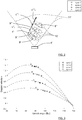
- FIG. 1 schematically shows a top view of an ego vehicle 1 arranged to run in a direction D with a velocity v ego , here coinciding with a system x-axis 21.
- the vehicle 1 comprises a vehicle radar system 3 which in turn comprises a transceiver arrangement 4 and a control unit 5.
- the vehicle radar system 3 is arranged to distinguish and/or resolve single targets from the surroundings by transmitting signals 2a and receiving reflected signals 2b and using a Doppler effect in a previously well-known manner, the transceiver arrangement 4 having a certain field of view 11.
- the vehicle radar system 3 is thus arranged to provide data regarding azimuth angle and radial velocity for a possible target object 6 by simultaneously sampling and analyzing phase and amplitude of the received signals 2b by means of Doppler signal processing in a previously known manner.
- the radar signals may for example be in the form of FMCW (Frequency Modulated Continuous Wave) Doppler signals operating at 77 GHz.
- a measured radial velocity v dm the Doppler velocity
- a measured azimuth angle ⁇ m between a radial direction of observation and a radar system reference line such as the x-axis 21, as well as a measured radial distance r m between the transceiver arrangement 4 and a detection 9 are acquired for each one of a plurality of detections 9, 20 (only a few indicated in Figure 1 for reasons of clarity), where there is a number N of detections 9 that belong to the target object 6 among a total number M ⁇ N of detections 9, 20.
- Some of the detections 9 can be grouped as a tracked object, providing a common motion state for an extended object 10.
- the motion state of an object describes, e.g., the distance from the ego vehicle 1 to a target object 6, a complete, relative or absolute, velocity vector of the object in relation to the ego vehicle, and a complete, relative or absolute, acceleration vector of the object in relation to the ego vehicle.
- the motion state of tracked objects is updated continuously to reflect changes in object motion.
- the target object 6 and its corresponding detections 9 have a relative velocity v t that has a velocity x-component v x and a velocity y-component v y .
- the x-component v x runs parallel to the x-axis 21 and the y-component v y runs parallel to a y-axis 22, which in turn runs perpendicular to the x-axis 21.
- the velocity y-component v y there is a corresponding acceleration y-component a y .
- V dm V x cos ⁇ m + V y sin ⁇ m + w as illustrated more in detail in the lower left part of Figure 1 .
- w denotes noise. The present disclosure is directed towards a principle, and although practically present, the noise w is omitted in the rest of the text.
- V dm 1 V dm 2 ⁇ V dm N cos ⁇ m 1 sin ⁇ m 1 cos ⁇ m 2 sin ⁇ m 2 ⁇ ⁇ cos ⁇ mN sin ⁇ mN V x V y
- Random Sample Consensus can be used to find the optimal solution, and it is robust to noise and outliers.
- This algorithm successively picks two random detections, and solves the above equation for the velocity components v x , v y using only these two detections.
- Each one of the resulting random hypotheses is evaluated and the best fit which best describes the remaining detections is selected.
- detections from multiple radar cycles from the past can be added to increase the number of detections, and hence the number of equations. This, however, is only applicable if the velocity vector does not change.
- a radar cycle is one observation phase during which the vehicle radar system 3 is arranged to acquire data, process said data on several signal processing levels and to send out available results.
- This can be a fixed time interval, or it can be a dynamic time interval depending on environment conditions and processing load.
- the detections 9', 9'', 9"', 9'''' for each radar cycle are shown with corresponding circles, crosses, squares and triangles.
- Figure 3 shows a graphic illustration of radial Doppler velocity as a function of azimuth angle for the accelerating target object 6'.
- V dm 1 V dm 2 ⁇ V dm N cos ⁇ m 1 sin ⁇ m 1 cos ⁇ m 2 sin ⁇ m 2 ⁇ ⁇ cos ⁇ mN sin ⁇ mN V x + a x ⁇ t V y + a x ⁇ t
- equation (2) it is desired to solve equation (4) for all M detections 9, 20 and to find the N detections 9 that originate from the same target object 6 and that correctly satisfy equation (4) .
- the four unknowns for the target velocity's and acceleration's x-and y-components v x , v y , a x , a y need to be solved for. This is possible with at least four equations. Similar to the example described above for velocity only, the RANSAC method can be used to robustly estimate the four unknowns.
- control unit 5 is adapted to consecutively select four detections 9 at random by means of which the four unknowns are solved. Out of the random hypotheses which are created this way, the control unit 5 is adapted to select the one which best describes the remaining detections.
- control unit 5 that is adapted to:
- This is performed for a plurality of radar cycles such that a corresponding plurality of sets of components v x , v y , a x , a y is acquired.
- the control unit 5 is then adapted to choose the set of components v x , v y , a x , a y that results in the largest number of inliers.
- the complexity can be reduced by using only three unknowns according to a following second example.
- At least three detections are needed, either all from different radar cycles, or two detections from one radar cycle, i.e. the current radar cycle, and one detection from another radar cycle, i.e. the previous radar cycle.
- the previous radar cycle only detections which are measured at the same cycle are used in a first processing stage for solving the velocity components v x , v y .
- additional detections from another radar cycle for example a previous radar cycle, are used to solve the acceleration component a.
- An important advantage for the approach according to the present disclosure is the fact that detections from multiple cycles can be used at the same time, which makes the algorithm robust even in case of low number of detections and in the presence of noise and outliers.
- the present disclosure also relates to a method for a vehicle radar system 3, where, for each one of a plurality of radar cycles, the method comprises:
- the method further comprises:
- the radar system may be implemented in any type of vehicles such as cars, trucks and buses as well as boats and aircraft.
- the radar transceiver 4 is adapted for any suitable type of Doppler radar in a Doppler radar system. There may be any number of radar transceivers 4 in the vehicle radar system 3, and they may be arranged for transmission and signals in any suitable direction. The plurality of sensing sectors or sensing bins may thus be directed in other desirable directions, such as rearwards or at the sides of the vehicle 1.
- Radar signal processing is performed in any kind of suitable control unit 5 comprised in the vehicle radar system 3, such as a DSP (Digital Signal Processor) or an RCU (Radar Control Unit) which according to some aspects comprises a DSP, or combination with separate or combined control unit arrangements.
- a DSP Digital Signal Processor
- RCU Rad Control Unit
- the present disclosure relates to a vehicle radar system 3 where, for each one of a plurality of radar cycles, the radar system 3 is arranged to provide a measured azimuth angle ⁇ m and a measured radial velocity v dm for a first plurality of detections 9, 20. For each one of said plurality of radar cycles, the radar system 3 is arranged to:
- the radar system 3 is adapted to group those detections 9 that correspond to inliers resulting from the chosen set of components v x , v y , a x , a y ; a, such that these detections 9 form an extended object 10.
- the second plurality of detections 9, 20 is the same as the first plurality of detections.
- the second plurality of detections belongs to another radar cycle, where the radar system 3 is arranged to:
- the second plurality of detections belongs to a previous radar cycle.
- is the magnitude of the relative velocity v r , such that said components v x , v y , a x , a y ; a are calculated by solving for these from the expression V dm V x + a V x V r ⁇ t cos ⁇ m + V y + a V y V r ⁇ t sin ⁇ m .
- the present disclosure relates to method for a vehicle radar system 3, where, for each one of a plurality of radar cycles, the method comprises:
- the method further comprises:
- the method further comprises:
- the second plurality of detections 9, 20 is the same as the first plurality of detections.
- the second plurality of detections belongs to another radar cycle, where the radar system 3 is arranged to:
- the second plurality of detections belongs to a previous radar cycle.
- ⁇ m constitutes a measured angle between a radar system reference line 21 and a direction towards the detection 9 in question.
- is the magnitude of the relative velocity v r , such that said components v x , v y , a x , a y ; a are calculated by solving for these from the expression V dm V x + a V x V r ⁇ t cos ⁇ m + V y + a V y V r ⁇ t sin ⁇ m .
Landscapes
- Engineering & Computer Science (AREA)
- Radar, Positioning & Navigation (AREA)
- Remote Sensing (AREA)
- Physics & Mathematics (AREA)
- Computer Networks & Wireless Communication (AREA)
- General Physics & Mathematics (AREA)
- Electromagnetism (AREA)
- Radar Systems Or Details Thereof (AREA)
Abstract
- Select one of these detections for each one of two velocity components (vx, vy) comprised in a set of components (vx, vy, ax, ay; a) to be determined.
- Select one detection from a second plurality of detections (9, 20) for each one of at least one corresponding acceleration component (ax, ay; a).
- Calculate said components (vx, vy, ax, ay; a) for the selected detections.
- Determine a calculated radial velocity (vdc) for each one of at least a part of the other detections in said first plurality of detections (9, 20) using the calculated components (vx, vy, ax, ay; a).
- Determine an error between each calculated and measured radial velocity (Vdc, Vdm).
- Determine the number of inliers.
Description
- The present disclosure relates to a vehicle radar system. For each one of a plurality of radar cycles, the vehicle radar system is arranged to provide a measured azimuth angle and a measured radial velocity for a first plurality of detections.
- Many vehicle radar systems comprise radar transceivers that are arranged for generating radar signals that are transmitted, reflected and received by means of appropriate antennas comprised in the radar system. The radar signals may for example be in the form of FMCW (Frequency Modulated Continuous Wave) signals.
- Radar provides important information about the environment and its participants, including moving objects and stationary environment to enable implementing automated vehicle systems such as speed control and collision prevention, as well as other such as auto alignment, online bumper fascia calibration, ego motion estimation, scene understanding, lane keeping assist (LKA) and automated driving (AD).
- At each radar cycle, the received radar signal provides a multitude of radar detections, and for each detection radial (Doppler) velocity Vd, radial distance r and azimuth angle θ are provided. The detections can be grouped as tracked objects, providing a common motion state for an extended object.
- The motion state of an object describes, e.g., the distance from the ego vehicle to the object, a complete, relative or absolute, velocity vector of the object in relation to the ego vehicle, and a complete, relative or absolute, acceleration vector of the object in relation to the ego vehicle. The motion state of tracked objects is updated continuously to reflect changes in object motion. For instance, acceleration and velocity vectors comprised in the motion state will increase in magnitude if a tracked object brakes or otherwise changes its velocity.
- It can be assumed that those detections that belong to a certain extended object have the same velocity vectors. Therefore, in order to be able to determine which ones of the acquired detections that have the same velocity vectors and thus can be determined to belong to a certain extended object, it is desirable to obtain complete vectors for velocity and acceleration for all the detections in as few radar cycles as possible in an uncomplicated and reliable manner.
- The object of the present disclosure is thus to provide a vehicle radar system that is adapted to determine complete vectors for velocity and acceleration in as few radar cycles as possible in an uncomplicated and reliable manner.
- This object is achieved by means of a vehicle radar system which, for each one of a plurality of radar cycles, is arranged to provide a measured azimuth angle and a measured radial velocity for a first plurality of detections. For each one of said plurality of radar cycles, the radar system is arranged to select one detection from said first plurality of detections for each one of two velocity components comprised in a set of components to be determined, where the two velocity components define a full velocity vector for a relative velocity, to select one detection from a second plurality of detections for each one of at least one corresponding acceleration component, and to calculate said components for the selected detections. For each one of said plurality of radar cycles, the radar system is furthermore arranged to determine a calculated radial velocity for each one of at least a part of the other detections in said first plurality of detections by means of said calculated components, to determine an error between each calculated radial velocity and the measured radial velocity, and to determine the number of inliers, where an inlier corresponds to an error that falls below an inlier threshold.
- This object is also achieved by means of a method for a vehicle radar system, where, for each one of a plurality of radar cycles, the method comprises acquiring a measured azimuth angle and a measured radial velocity for a plurality of detections associated with an object, selecting one detection from said first plurality of detections for each one of two velocity components comprised in a set of components to be determined, where the two velocity components define a full velocity vector for a relative velocity, and selecting one detection from a second plurality of detections for each one of at least one corresponding acceleration component and calculating said components for the selected detections.
- For each one of said plurality of radar cycles, the method further comprises determining a calculated radial velocity for each one of at least a part of the other detections in said first plurality of detections by means of said calculated components, determining an error between each calculated radial velocity and the measured radial velocity, and determining the number of inliers, where an inlier corresponds to an error that falls below an inlier threshold.
- The method comprises repeating the above for all radar cycles in said plurality of radar cycles; the method then comprises choosing the set of components that results in the largest number of inliers.
- The radar system is furthermore arranged to choose the set of components that results in the largest number of inliers.
- According to some aspects, the radar system is adapted to group those detections that correspond to inliers resulting from the chosen set of components, such that these detections form an extended object.
- According to some aspects, the second plurality of detections is the same as the first plurality of detections.
- According to some aspects, the second plurality of detections belongs to another radar cycle. The radar system is arranged to first calculate the velocity components for the selected detections, and then to calculate said at least one acceleration component by means of the calculated velocity components.
- According to some aspects, the radar system is arranged to calculate said components by solving for these from the expression

- According to some aspects, the radar system is adapted to substitute


- Other examples are disclosed in the dependent claims.
- A number of advantages are obtained by means of the present disclosure. Mainly, object tracking performance is improved, as well as ego dynamics estimation.
- Furthermore, detections from multiple cycles can be used at the same time, which makes the algorithm robust even in case of low number of detections and in the presence of noise and outliers.
- The present disclosure will now be described more in detail with reference to the appended drawings, where:
- Figure 1
- shows a schematic top view of an ego vehicle and a target vehicle;
- Figure 2
- shows a schematic illustration of an accelerating target object;
- Figure 3
- shows a graphic illustration of radial Doppler velocity as a function of azimuth angle for an accelerating target object;
- Figure 4
- shows a flowchart for methods according to the present disclosure.
-
Figure 1 schematically shows a top view of anego vehicle 1 arranged to run in a direction D with a velocity vego, here coinciding with asystem x-axis 21. Thevehicle 1 comprises avehicle radar system 3 which in turn comprises atransceiver arrangement 4 and acontrol unit 5. Thevehicle radar system 3 is arranged to distinguish and/or resolve single targets from the surroundings by transmittingsignals 2a and receivingreflected signals 2b and using a Doppler effect in a previously well-known manner, thetransceiver arrangement 4 having a certain field ofview 11. Thevehicle radar system 3 is thus arranged to provide data regarding azimuth angle and radial velocity for apossible target object 6 by simultaneously sampling and analyzing phase and amplitude of the receivedsignals 2b by means of Doppler signal processing in a previously known manner. The radar signals may for example be in the form of FMCW (Frequency Modulated Continuous Wave) Doppler signals operating at 77 GHz. - By means of the
vehicle radar system 3, a measured radial velocity vdm, the Doppler velocity, is determined, for example from the Doppler frequency and the Doppler phase shift. Furthermore, a measured azimuth angle θm between a radial direction of observation and a radar system reference line such as thex-axis 21, as well as a measured radial distance rm between thetransceiver arrangement 4 and adetection 9, are acquired for each one of a plurality ofdetections 9, 20 (only a few indicated inFigure 1 for reasons of clarity), where there is a number N ofdetections 9 that belong to thetarget object 6 among a total number M ≥ N ofdetections detections 9 can be grouped as a tracked object, providing a common motion state for anextended object 10. - The motion state of an object describes, e.g., the distance from the
ego vehicle 1 to atarget object 6, a complete, relative or absolute, velocity vector of the object in relation to the ego vehicle, and a complete, relative or absolute, acceleration vector of the object in relation to the ego vehicle. The motion state of tracked objects is updated continuously to reflect changes in object motion. - In order to be able to identify and group those
detections 9 that belong to a certainextended object 10, it is desired to determine which detections that have the same velocity vector, which now will be described for a first example. - The
target object 6 and itscorresponding detections 9 have a relative velocity vt that has a velocity x-component vx and a velocity y-component vy. The x-component vx runs parallel to thex-axis 21 and the y-component vy runs parallel to a y-axis 22, which in turn runs perpendicular to thex-axis 21. For the velocity x-component vx there is a corresponding acceleration x-component ax, and for the velocity y-component vy, there is a corresponding acceleration y-component ay. - Assuming that all the
detections 9 which are received from an extended object have the same direction of velocity, then the measured radial velocity Vdm of each one of thesedetections 9 is given by projecting the relative velocity vector vt onto the radial direction. This is given by:
Figure 1 . Here, w denotes noise. The present disclosure is directed towards a principle, and although practically present, the noise w is omitted in the rest of the text. - For an extended object,
multiple detections 9 originate from thesame target object 6, and each detection has its individual measured radial velocity Vdm. For allN detections 9 that originate from thesame target object 6, a set of equations will be:
- It is desired to solve equation (2) for all
M detections N detections 9 that originate from thesame target object 6 and that correctly satisfy equation (2). - As there are two unknowns, at least two equations are needed so solve for the full velocity vector vx, vy. In case more detections are available, and hence more equations are available, the system becomes overdetermined and a least squares inversion can give the solution for the full velocity vector vx, vy.
- The Random Sample Consensus (RANSAC) approach can be used to find the optimal solution, and it is robust to noise and outliers. This algorithm successively picks two random detections, and solves the above equation for the velocity components vx, vy using only these two detections.
- Each one of the resulting random hypotheses is evaluated and the best fit which best describes the remaining detections is selected. To increase robustness, detections from multiple radar cycles from the past can be added to increase the number of detections, and hence the number of equations. This, however, is only applicable if the velocity vector does not change.
- In this context, a radar cycle is one observation phase during which the
vehicle radar system 3 is arranged to acquire data, process said data on several signal processing levels and to send out available results. This can be a fixed time interval, or it can be a dynamic time interval depending on environment conditions and processing load. - When the
target object 6 is moving with an acceleration, the Doppler velocity of thedetections 9 changes rapidly in each radar cycle, and therefore a standard RANSAC fit on data from multiple radar cycles does not give an accurate solution. With reference toFigure 2 , the relative velocity v't v"t v"'t v''''t for an extended target object 10' that is moving away from a radar transceiver 4' with a certain constant acceleration is shown for four consecutive radar cycles in the radar transceiver's field of view 11'. - The detections 9', 9'', 9"', 9'''' for each radar cycle are shown with corresponding circles, crosses, squares and triangles.
- Correspondingly,
Figure 3 shows a graphic illustration of radial Doppler velocity as a function of azimuth angle for the accelerating target object 6'. - Therefore, in the cases where the
target object 6 has a constant acceleration ax, ay, equation (1) becomes:
- For all
N detections 9 that originate from thesame target object 6, a set of equations will be:
- As for equation (2), it is desired to solve equation (4) for all M
detections N detections 9 that originate from thesame target object 6 and that correctly satisfy equation (4) . - Thus, the four unknowns for the target velocity's and acceleration's x-and y-components vx, vy, ax, ay need to be solved for. This is possible with at least four equations. Similar to the example described above for velocity only, the RANSAC method can be used to robustly estimate the four unknowns.
- According to the present disclosure, for a certain radar cycle, the
control unit 5 is adapted to consecutively select fourdetections 9 at random by means of which the four unknowns are solved. Out of the random hypotheses which are created this way, thecontrol unit 5 is adapted to select the one which best describes the remaining detections. - This is accomplished by the
control unit 5 that is adapted to: - Determine a calculated radial velocity vdc for each one of the selected detections by means of the calculated components vx, vy, ax, ay using equation (3) for vdc instead of Vdm.
- Determine an error between the calculated radial velocity vdc and the measured radial velocity Vdm.
- Determine the number of inliers, where an inlier corresponds to an error that falls below an inlier threshold.
- This is performed for a plurality of radar cycles such that a corresponding plurality of sets of components vx, vy, ax, ay is acquired. The
control unit 5 is then adapted to choose the set of components vx, vy, ax, ay that results in the largest number of inliers. - An important advantage for this approach is its robustness to noise. This is achieved because all of the four unknowns are optimized simultaneously by solving a single globally optimal equation.
- Inverting the above equation is feasible in the general case, but it is computationally expensive. Therefore, according to some aspects of the present disclosure, to simplify the calculations only detections which are measured at the same cycle are used in a first processing stage for solving the velocity components vx, vy. Then, additional detections from another radar cycle, for example a previous radar cycle, are used to solve the acceleration components ax, ay.
- According to some aspects, the complexity can be reduced by using only three unknowns according to a following second example.
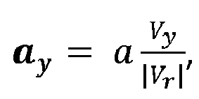
- In practical applications, the most relevant case of acceleration is in a longitudinal direction, in a driving direction. Assuming that acceleration always is in the driving direction and there is no lateral movement, the acceleration components ax, ay are substituted according to


- Then rewriting equation (3) results in:

- Simplifying equation (5) results in:


- Substituting


- In order to make a fit, at least three detections are needed, either all from different radar cycles, or two detections from one radar cycle, i.e. the current radar cycle, and one detection from another radar cycle, i.e. the previous radar cycle. In that case, as in the previous first example, only detections which are measured at the same cycle are used in a first processing stage for solving the velocity components vx, vy. Then, additional detections from another radar cycle, for example a previous radar cycle, are used to solve the acceleration component a.
- Optimization is achieved for three unknown variables, the target velocity's x-and y-components vx, vy and the simplified acceleration component a simultaneously.
- An important advantage for the approach according to the present disclosure is the fact that detections from multiple cycles can be used at the same time, which makes the algorithm robust even in case of low number of detections and in the presence of noise and outliers.
- With reference to
Figure 4 , the present disclosure also relates to a method for avehicle radar system 3, where, for each one of a plurality of radar cycles, the method comprises: - 12: Acquiring a measured azimuth angle θm and a measured radial velocity Vdm for a plurality of
detections 9 associated with anobject 6. - 13: Selecting one detection from said first plurality of
detections - 14: Selecting one detection from a second plurality of
detections - 15: Calculating said components vx, vy, ax, ay; a for the selected detections.
- 16: Determining a calculated radial velocity vdc for each one of at least a part of the other detections in said first plurality of
detections - 17: Determining an error between each calculated radial velocity vdc and the measured radial velocity Vdm.
- 18: Determining the number of inliers, where an inlier corresponds to an error that falls below an inlier threshold.
- 19: Repeating the above for all radar cycles in said plurality of radar cycles.
- 23: Choosing the set of components vx, vy, ax, ay; a that results in the largest number of inliers.
- According to some aspects, the method further comprises:
- 24: Grouping those
detections 9 that correspond to inliers resulting from the chosen set of components vx, vy, ax, ay; a, such that thesedetections 9 form anextended object 10. - The present disclosure is not limited to the examples above, but may vary freely within the scope of the appended claims. For example, the radar system may be implemented in any type of vehicles such as cars, trucks and buses as well as boats and aircraft.
- The
radar transceiver 4 is adapted for any suitable type of Doppler radar in a Doppler radar system. There may be any number ofradar transceivers 4 in thevehicle radar system 3, and they may be arranged for transmission and signals in any suitable direction. The plurality of sensing sectors or sensing bins may thus be directed in other desirable directions, such as rearwards or at the sides of thevehicle 1. - Radar signal processing is performed in any kind of
suitable control unit 5 comprised in thevehicle radar system 3, such as a DSP (Digital Signal Processor) or an RCU (Radar Control Unit) which according to some aspects comprises a DSP, or combination with separate or combined control unit arrangements. - Generally, the present disclosure relates to a
vehicle radar system 3 where, for each one of a plurality of radar cycles, theradar system 3 is arranged to provide a measured azimuth angle θm and a measured radial velocity v dm for a first plurality ofdetections radar system 3 is arranged to: - select one detection from said first plurality of
detections - select one detection from a second plurality of
detections - calculate said components vx, vy, ax, ay; a for the selected detections;
- determine a calculated radial velocity vdc for each one of at least a part of the other detections in said first plurality of
detections - determine an error between each calculated radial velocity vdc and the measured radial velocity vdm;
- determine the number of inliers, where an inlier corresponds to an error that falls below an inlier threshold;
- According to some aspects, the
radar system 3 is adapted to group thosedetections 9 that correspond to inliers resulting from the chosen set of components vx, vy, ax, ay; a, such that thesedetections 9 form anextended object 10. - According to some aspects, the second plurality of
detections - According to some aspects, the second plurality of detections belongs to another radar cycle, where the
radar system 3 is arranged to: - first calculate the velocity components vx, vy for the selected detections;
- then calculate said at least one acceleration component ax, ay; a by means of the calculated velocity components vx, vy.
- According to some aspects, the second plurality of detections belongs to a previous radar cycle.
- According to some aspects, the
radar system 3 is arranged to calculate said components vx, vy, ax, ay; a by solving for these from the expression
system reference line 21 and a direction towards thedetection 9 in question. - According to some aspects, the
radar system 3 is adapted to substitute


- Generally, the present disclosure relates to method for a
vehicle radar system 3, where, for each one of a plurality of radar cycles, the method comprises: - 12: acquiring a measured azimuth angle θm and a measured radial velocity vdm for a plurality of
detections 9 associated with anobject 6. - For each one of said plurality of radar cycles, the method further comprises:
- 13: selecting one detection from said first plurality of
detections - 14: selecting one detection from a second plurality of
detections - 15: calculating said components vx, vy, ax, ay; a for the selected detections;
- 16: determining a calculated radial velocity vdc for each one of at least a part of the other detections in said first plurality of
detections - 17: determining an error between each calculated radial velocity vdc and the measured radial velocity vdm; and
- 18: determining the number of inliers, where an inlier corresponds to an error that falls below an inlier threshold; and
- 19: repeating the above for all radar cycles in said plurality of radar cycles;
- 23: choosing the set of components vx, vy, ax, ay; a that results in the largest number of inliers.
- According to some aspects, the method further comprises:
- 24: grouping those
detections 9 that correspond to inliers resulting from the chosen set of components vx, vy, ax, ay; a, such that thesedetections 9 form anextended object 10. - According to some aspects, the second plurality of
detections - According to some aspects, the second plurality of detections belongs to another radar cycle, where the
radar system 3 is arranged to: - first calculate the velocity components vx, vy for the selected detections;
- then calculate said at least one acceleration component ax, ay; a by means of the calculated velocity components vx, vy.
- According to some aspects, the second plurality of detections belongs to a previous radar cycle.
- According to some aspects, the method comprises calculating said components vx, vy, ax, ay; a by solving for these from the expression

- for each selected detection, where θm constitutes a measured angle between a radar
system reference line 21 and a direction towards thedetection 9 in question. - According to some aspects, the radar system (3) is adapted to substitute


Claims (14)
- A vehicle radar system (3) where, for each one of a plurality of radar cycles, the radar system (3) is arranged to provide a measured azimuth angle (θm) and a measured radial velocity (vdm) for a first plurality of detections (9, 20), characterized in that, for each one of said plurality of radar cycles, the radar system (3) is arranged to:- select one detection from said first plurality of detections (9, 20) for each one of two velocity components (vx, vy) comprised in a set of components (vx, vy, ax, ay; a) to be determined, where the two velocity components (vx, vy) define a full velocity vector for a relative velocity (vr) ;- select one detection from a second plurality of detections (9, 20) for each one of at least one corresponding acceleration component (ax, ay; a) ;- calculate said components (vx, vy, ax, ay; a) for the selected detections;- determine a calculated radial velocity (vdc) for each one of at least a part of the other detections in said first plurality of detections (9, 20) by means of said calculated components (vx, vy, ax, ay; a);- determine an error between each calculated radial velocity (vdc) and the measured radial velocity (vdm) ;- determine the number of inliers, where an inlier corresponds to an error that falls below an inlier threshold;where the radar system (3) furthermore is arranged to choose the set of components (vx, vy, ax, ay; a) that results in the largest number of inliers.
- The vehicle radar system (3) according to claim 1, wherein the radar system (3) is adapted to group those detections (9) that correspond to inliers resulting from the chosen set of components (vx, vy, ax, ay; a), such that these detections (9) form an extended object (10).
- The vehicle radar system (3) according to any one of the claims 1 or 2, wherein the second plurality of detections (9, 20) is the same as the first plurality of detections.
- The vehicle radar system (3) according to any one of the claims 1 or 2, wherein the second plurality of detections belongs to another radar cycle, where the radar system (3) is arranged to:- first calculate the velocity components (vx, vy) for the selected detections;- then calculate said at least one acceleration component (ax, ay; a) by means of the calculated velocity components (vx, vy).
- The vehicle radar system (3) according to claim 4, wherein the second plurality of detections belongs to a previous radar cycle.
- The vehicle radar system (3) according to any one of the previous claims, wherein the radar system (3) is arranged to calculate said components (vx, vy, ax, ay; a) by solving for these from the expression

- The vehicle radar system (3) according to claim 6, wherein the radar system (3) is adapted to substitute


- A method for a vehicle radar system (3), where, for each one of a plurality of radar cycles, the method comprises:(12) acquiring a measured azimuth angle (θm) and a measured radial velocity (vdm) for a plurality of detections (9) associated with an object (6), andcharacterized in that, for each one of said plurality of radar cycles, the method further comprises:(13) selecting one detection from said first plurality of detections (9, 20) for each one of two velocity components (vx, vy) comprised in a set of components (vx, vy, ax, ay; a) to be determined, where the two velocity components (vx, vy) define a full velocity vector for a relative velocity (vr);(14) selecting one detection from a second plurality of detections (9, 20) for each one of at least one corresponding acceleration component (ax, ay; a) ;(15) calculating said components (vx, vy, ax, ay; a) for the selected detections;(16) determining a calculated radial velocity (vdc) for each one of at least a part of the other detections in said first plurality of detections (9, 20) by means of said calculated components (vx, vy, ax, ay; a) ;(17) determining an error between each calculated radial velocity (vdc) and the measured radial velocity (vdm) ; and(18) determining the number of inliers, where an inlier corresponds to an error that falls below an inlier threshold; and(19) repeating the above for all radar cycles in said plurality of radar cycles;where the method then comprises:(23) choosing the set of components (vx, vy, ax, ay; a) that results in the largest number of inliers.
- The method according to claim 8, wherein the method further comprises:(24) grouping those detections (9) that correspond to inliers resulting from the chosen set of components (vx, vy, ax, ay; a), such that these detections (9) form an extended object (10) .
- The method according to any one of the claims 8 or 9, wherein the second plurality of detections (9, 20) is the same as the first plurality of detections.
- The method according to any one of the claims 8 or 9, wherein the second plurality of detections belongs to another radar cycle, where the radar system (3) is arranged to:- first calculate the velocity components (vx, vy) for the selected detections;- then calculate said at least one acceleration component (ax, ay; a) by means of the calculated velocity components (vx, vy).
- The method according to claim 11, wherein the second plurality of detections belongs to a previous radar cycle.
- The method according to any one of the claims 8-12, wherein the method comprises calculating said components (vx, vy, ax, ay; a) by solving for these from the expression

- The method according to claim 13, wherein the radar system (3) is adapted to substitute


Priority Applications (4)
| Application Number | Priority Date | Filing Date | Title |
|---|---|---|---|
| EP17206670.6A EP3499265B1 (en) | 2017-12-12 | 2017-12-12 | Determining object motion and acceleration vector in a vehicle radar system |
| US16/772,505 US11536830B2 (en) | 2017-12-12 | 2018-11-20 | Determining object motion and acceleration vector in a vehicle radar system |
| PCT/EP2018/081947 WO2019115179A1 (en) | 2017-12-12 | 2018-11-20 | Determining object motion and acceleration vector in a vehicle radar system |
| CN201880076086.2A CN111386476B (en) | 2017-12-12 | 2018-11-20 | Determining Object Motion and Acceleration Vectors in Vehicle Radar Systems |
Applications Claiming Priority (1)
| Application Number | Priority Date | Filing Date | Title |
|---|---|---|---|
| EP17206670.6A EP3499265B1 (en) | 2017-12-12 | 2017-12-12 | Determining object motion and acceleration vector in a vehicle radar system |
Publications (2)
| Publication Number | Publication Date |
|---|---|
| EP3499265A1 true EP3499265A1 (en) | 2019-06-19 |
| EP3499265B1 EP3499265B1 (en) | 2020-08-19 |
Family
ID=60673167
Family Applications (1)
| Application Number | Title | Priority Date | Filing Date |
|---|---|---|---|
| EP17206670.6A Active EP3499265B1 (en) | 2017-12-12 | 2017-12-12 | Determining object motion and acceleration vector in a vehicle radar system |
Country Status (4)
| Country | Link |
|---|---|
| US (1) | US11536830B2 (en) |
| EP (1) | EP3499265B1 (en) |
| CN (1) | CN111386476B (en) |
| WO (1) | WO2019115179A1 (en) |
Families Citing this family (10)
| Publication number | Priority date | Publication date | Assignee | Title |
|---|---|---|---|---|
| GB2590115B (en) * | 2019-09-13 | 2023-12-06 | Motional Ad Llc | Extended object tracking using radar |
| CN112782694B (en) * | 2021-01-22 | 2023-06-30 | 重庆秦嵩科技有限公司 | Radar signal processing method and system based on multi-core DSP |
| EP4036601A1 (en) * | 2021-01-29 | 2022-08-03 | Aptiv Technologies Limited | Radar data processing for vehicle ego-motion estimation |
| JP7608244B2 (en) * | 2021-03-31 | 2025-01-06 | 古河電気工業株式会社 | Radar device, target detection method, and target detection program |
| EP4075164B1 (en) | 2021-04-15 | 2025-01-08 | Aptiv Technologies AG | Method and device for estimating a velocity of an object |
| EP4394445A4 (en) * | 2021-08-26 | 2024-11-27 | Panasonic Intellectual Property Management Co., Ltd. | DETECTION DEVICE, PROCESSING DEVICE, AND DATA PROCESSING METHOD |
| US12326497B2 (en) * | 2021-11-24 | 2025-06-10 | Sony Group Corporation | Circuitry and method |
| US12313725B2 (en) * | 2022-09-30 | 2025-05-27 | Zadar Labs, Inc. | System and method for radar static-dynamic segmentation |
| US12313770B2 (en) * | 2022-09-30 | 2025-05-27 | Zadar Labs, Inc. | System and method for radar calibration |
| US12372641B2 (en) * | 2022-12-09 | 2025-07-29 | Nxp B.V. | Ego velocity estimator for radar systems |
Citations (1)
| Publication number | Priority date | Publication date | Assignee | Title |
|---|---|---|---|---|
| DE102016206550A1 (en) * | 2016-04-19 | 2017-10-19 | Conti Temic Microelectronic Gmbh | Device and method for determining an object kinematics of a moving object |
Family Cites Families (12)
| Publication number | Priority date | Publication date | Assignee | Title |
|---|---|---|---|---|
| DE102012024998A1 (en) * | 2012-12-19 | 2014-06-26 | Valeo Schalter Und Sensoren Gmbh | Method for determining lateral velocity of target object relative to motor vehicle by driver assistance system of motor vehicle, involves detecting value of radial velocity to two target echoes |
| DE102013104443B4 (en) * | 2013-04-30 | 2022-03-17 | Jenoptik Robot Gmbh | Traffic monitoring system for measuring the speed and allocation of moving vehicles in a multi-target recording module |
| DE102013018310A1 (en) * | 2013-10-31 | 2015-04-30 | Daimler Ag | Method for determining a movement of an object |
| DE102014212284A1 (en) * | 2014-06-26 | 2015-12-31 | Robert Bosch Gmbh | MIMO radar measurement method |
| US10627480B2 (en) * | 2014-07-17 | 2020-04-21 | Texas Instruments Incorporated | Distributed radar signal processing in a radar system |
| DE102014010990B4 (en) * | 2014-07-29 | 2021-06-17 | Jenoptik Robot Gmbh | Method and device for detecting a speed and a distance of at least one object in relation to a receiver of a received signal |
| US9784829B2 (en) * | 2015-04-06 | 2017-10-10 | GM Global Technology Operations LLC | Wheel detection and its application in object tracking and sensor registration |
| US10317518B2 (en) * | 2015-07-20 | 2019-06-11 | Brigham Young University (Byu) | Phased array radar systems for small unmanned aerial vehicles |
| CN105093220A (en) * | 2015-08-28 | 2015-11-25 | 中国科学院国家空间科学中心 | Method for measuring ocean surface flow speed by use of real aperture radar |
| US10094919B2 (en) * | 2015-10-06 | 2018-10-09 | GM Global Technology Operations LLC | Radar-vision fusion for target velocity estimation |
| EP3415948B1 (en) * | 2017-06-12 | 2021-11-10 | Aptiv Technologies Limited | A method of determining the de-aliased range rate of a target |
| US20180024239A1 (en) * | 2017-09-25 | 2018-01-25 | GM Global Technology Operations LLC | Systems and methods for radar localization in autonomous vehicles |
-
2017
- 2017-12-12 EP EP17206670.6A patent/EP3499265B1/en active Active
-
2018
- 2018-11-20 WO PCT/EP2018/081947 patent/WO2019115179A1/en not_active Ceased
- 2018-11-20 CN CN201880076086.2A patent/CN111386476B/en active Active
- 2018-11-20 US US16/772,505 patent/US11536830B2/en active Active
Patent Citations (1)
| Publication number | Priority date | Publication date | Assignee | Title |
|---|---|---|---|---|
| DE102016206550A1 (en) * | 2016-04-19 | 2017-10-19 | Conti Temic Microelectronic Gmbh | Device and method for determining an object kinematics of a moving object |
Non-Patent Citations (2)
| Title |
|---|
| KELLNER DOMINIK ET AL: "Instantaneous lateral velocity estimation of a vehicle using Doppler radar", PROCEEDINGS OF THE 16TH INTERNATIONAL CONFERENCE ON INFORMATION FUSION, ISIF ( INTL SOCIETY OF INFORMATION FUSI, 9 July 2013 (2013-07-09), pages 877 - 884, XP032512378, ISBN: 978-605-86311-1-3, [retrieved on 20131018] * |
| KELLNER DOMINIK ET AL: "Tracking of Extended Objects with High-Resolution Doppler Radar", IEEE TRANSACTIONS ON INTELLIGENT TRANSPORTATION SYSTEMS, IEEE, PISCATAWAY, NJ, USA, vol. 17, no. 5, 1 May 2016 (2016-05-01), pages 1341 - 1353, XP011608058, ISSN: 1524-9050, [retrieved on 20160429], DOI: 10.1109/TITS.2015.2501759 * |
Also Published As
| Publication number | Publication date |
|---|---|
| EP3499265B1 (en) | 2020-08-19 |
| CN111386476A (en) | 2020-07-07 |
| WO2019115179A1 (en) | 2019-06-20 |
| US11536830B2 (en) | 2022-12-27 |
| US20200386883A1 (en) | 2020-12-10 |
| CN111386476B (en) | 2023-06-13 |
Similar Documents
| Publication | Publication Date | Title |
|---|---|---|
| EP3499265B1 (en) | Determining object motion and acceleration vector in a vehicle radar system | |
| US12253591B2 (en) | Systems and methods for interpolated virtual aperture radar tracking | |
| CN114144697B (en) | System and method for interpolated virtual aperture radar tracking | |
| EP3252501B1 (en) | Enhanced object detection and motion state estimation for a vehicle environment detection system | |
| US11226407B2 (en) | Vehicle radar system arranged for determining an unoccupied domain | |
| EP4047391B1 (en) | Radar-based target tracker | |
| US11092686B2 (en) | Method, apparatus and device for doppler compensation in a time switched MIMO radar system | |
| US11180137B2 (en) | Vehicle environmental detection system for parking detection | |
| EP3588135B1 (en) | Method of determining an alignment error of an antenna and vehicle with an antenna and a detection device | |
| CN111712722B (en) | Estimation of the lateral or Cartesian velocity of a point target using a radar sensor | |
| JP2019032285A (en) | Radar apparatus and target detection method | |
| JP2019039686A (en) | Radar device and target detection method | |
| US20240142600A1 (en) | Object-position detector apparatus and detection method for estimating position of object based on rader information from rader apparatus | |
| CN110678776B (en) | System for enhanced object tracking | |
| EP3290945A1 (en) | Misalignment detection for a vehicle radar sensor | |
| US12468031B2 (en) | Radar device for vehicle | |
| JP2019200082A (en) | Azimuth calculation device and azimuth calculation method | |
| Huang et al. | Multi-target tracking algorithm in the complicated road condition for automotive millimeter-wave radar | |
| Stolz et al. | Direction of movement estimation of cyclists with a high-resolution automotive radar | |
| US12372641B2 (en) | Ego velocity estimator for radar systems | |
| JP7608244B2 (en) | Radar device, target detection method, and target detection program | |
| CN117538857A (en) | Rate disambiguation method and device for radar, radar and medium | |
| JP2021188922A (en) | Signal processing device |
Legal Events
| Date | Code | Title | Description |
|---|---|---|---|
| PUAI | Public reference made under article 153(3) epc to a published international application that has entered the european phase |
Free format text: ORIGINAL CODE: 0009012 |
|
| STAA | Information on the status of an ep patent application or granted ep patent |
Free format text: STATUS: THE APPLICATION HAS BEEN PUBLISHED |
|
| AK | Designated contracting states |
Kind code of ref document: A1 Designated state(s): AL AT BE BG CH CY CZ DE DK EE ES FI FR GB GR HR HU IE IS IT LI LT LU LV MC MK MT NL NO PL PT RO RS SE SI SK SM TR |
|
| AX | Request for extension of the european patent |
Extension state: BA ME |
|
| STAA | Information on the status of an ep patent application or granted ep patent |
Free format text: STATUS: REQUEST FOR EXAMINATION WAS MADE |
|
| 17P | Request for examination filed |
Effective date: 20191211 |
|
| RBV | Designated contracting states (corrected) |
Designated state(s): AL AT BE BG CH CY CZ DE DK EE ES FI FR GB GR HR HU IE IS IT LI LT LU LV MC MK MT NL NO PL PT RO RS SE SI SK SM TR |
|
| REG | Reference to a national code |
Ref country code: DE Ref legal event code: R079 Ref document number: 602017021866 Country of ref document: DE Free format text: PREVIOUS MAIN CLASS: G01S0013930000 Ipc: G01S0013931000 |
|
| GRAP | Despatch of communication of intention to grant a patent |
Free format text: ORIGINAL CODE: EPIDOSNIGR1 |
|
| STAA | Information on the status of an ep patent application or granted ep patent |
Free format text: STATUS: GRANT OF PATENT IS INTENDED |
|
| RIC1 | Information provided on ipc code assigned before grant |
Ipc: G01S 13/72 20060101ALI20200131BHEP Ipc: G01S 13/931 20200101AFI20200131BHEP Ipc: G01S 13/58 20060101ALI20200131BHEP Ipc: G01S 13/42 20060101ALI20200131BHEP |
|
| INTG | Intention to grant announced |
Effective date: 20200310 |
|
| GRAS | Grant fee paid |
Free format text: ORIGINAL CODE: EPIDOSNIGR3 |
|
| GRAA | (expected) grant |
Free format text: ORIGINAL CODE: 0009210 |
|
| STAA | Information on the status of an ep patent application or granted ep patent |
Free format text: STATUS: THE PATENT HAS BEEN GRANTED |
|
| AK | Designated contracting states |
Kind code of ref document: B1 Designated state(s): AL AT BE BG CH CY CZ DE DK EE ES FI FR GB GR HR HU IE IS IT LI LT LU LV MC MK MT NL NO PL PT RO RS SE SI SK SM TR |
|
| REG | Reference to a national code |
Ref country code: CH Ref legal event code: EP |
|
| REG | Reference to a national code |
Ref country code: DE Ref legal event code: R096 Ref document number: 602017021866 Country of ref document: DE |
|
| REG | Reference to a national code |
Ref country code: AT Ref legal event code: REF Ref document number: 1304578 Country of ref document: AT Kind code of ref document: T Effective date: 20200915 |
|
| REG | Reference to a national code |
Ref country code: IE Ref legal event code: FG4D |
|
| REG | Reference to a national code |
Ref country code: LT Ref legal event code: MG4D |
|
| REG | Reference to a national code |
Ref country code: NL Ref legal event code: MP Effective date: 20200819 |
|
| PG25 | Lapsed in a contracting state [announced via postgrant information from national office to epo] |
Ref country code: NO Free format text: LAPSE BECAUSE OF FAILURE TO SUBMIT A TRANSLATION OF THE DESCRIPTION OR TO PAY THE FEE WITHIN THE PRESCRIBED TIME-LIMIT Effective date: 20201119 Ref country code: PT Free format text: LAPSE BECAUSE OF FAILURE TO SUBMIT A TRANSLATION OF THE DESCRIPTION OR TO PAY THE FEE WITHIN THE PRESCRIBED TIME-LIMIT Effective date: 20201221 Ref country code: FI Free format text: LAPSE BECAUSE OF FAILURE TO SUBMIT A TRANSLATION OF THE DESCRIPTION OR TO PAY THE FEE WITHIN THE PRESCRIBED TIME-LIMIT Effective date: 20200819 Ref country code: LT Free format text: LAPSE BECAUSE OF FAILURE TO SUBMIT A TRANSLATION OF THE DESCRIPTION OR TO PAY THE FEE WITHIN THE PRESCRIBED TIME-LIMIT Effective date: 20200819 Ref country code: GR Free format text: LAPSE BECAUSE OF FAILURE TO SUBMIT A TRANSLATION OF THE DESCRIPTION OR TO PAY THE FEE WITHIN THE PRESCRIBED TIME-LIMIT Effective date: 20201120 Ref country code: SE Free format text: LAPSE BECAUSE OF FAILURE TO SUBMIT A TRANSLATION OF THE DESCRIPTION OR TO PAY THE FEE WITHIN THE PRESCRIBED TIME-LIMIT Effective date: 20200819 Ref country code: BG Free format text: LAPSE BECAUSE OF FAILURE TO SUBMIT A TRANSLATION OF THE DESCRIPTION OR TO PAY THE FEE WITHIN THE PRESCRIBED TIME-LIMIT Effective date: 20201119 Ref country code: HR Free format text: LAPSE BECAUSE OF FAILURE TO SUBMIT A TRANSLATION OF THE DESCRIPTION OR TO PAY THE FEE WITHIN THE PRESCRIBED TIME-LIMIT Effective date: 20200819 |
|
| REG | Reference to a national code |
Ref country code: AT Ref legal event code: MK05 Ref document number: 1304578 Country of ref document: AT Kind code of ref document: T Effective date: 20200819 |
|
| PG25 | Lapsed in a contracting state [announced via postgrant information from national office to epo] |
Ref country code: IS Free format text: LAPSE BECAUSE OF FAILURE TO SUBMIT A TRANSLATION OF THE DESCRIPTION OR TO PAY THE FEE WITHIN THE PRESCRIBED TIME-LIMIT Effective date: 20201219 Ref country code: PL Free format text: LAPSE BECAUSE OF FAILURE TO SUBMIT A TRANSLATION OF THE DESCRIPTION OR TO PAY THE FEE WITHIN THE PRESCRIBED TIME-LIMIT Effective date: 20200819 Ref country code: RS Free format text: LAPSE BECAUSE OF FAILURE TO SUBMIT A TRANSLATION OF THE DESCRIPTION OR TO PAY THE FEE WITHIN THE PRESCRIBED TIME-LIMIT Effective date: 20200819 Ref country code: NL Free format text: LAPSE BECAUSE OF FAILURE TO SUBMIT A TRANSLATION OF THE DESCRIPTION OR TO PAY THE FEE WITHIN THE PRESCRIBED TIME-LIMIT Effective date: 20200819 Ref country code: LV Free format text: LAPSE BECAUSE OF FAILURE TO SUBMIT A TRANSLATION OF THE DESCRIPTION OR TO PAY THE FEE WITHIN THE PRESCRIBED TIME-LIMIT Effective date: 20200819 |
|
| PG25 | Lapsed in a contracting state [announced via postgrant information from national office to epo] |
Ref country code: RO Free format text: LAPSE BECAUSE OF FAILURE TO SUBMIT A TRANSLATION OF THE DESCRIPTION OR TO PAY THE FEE WITHIN THE PRESCRIBED TIME-LIMIT Effective date: 20200819 Ref country code: DK Free format text: LAPSE BECAUSE OF FAILURE TO SUBMIT A TRANSLATION OF THE DESCRIPTION OR TO PAY THE FEE WITHIN THE PRESCRIBED TIME-LIMIT Effective date: 20200819 Ref country code: CZ Free format text: LAPSE BECAUSE OF FAILURE TO SUBMIT A TRANSLATION OF THE DESCRIPTION OR TO PAY THE FEE WITHIN THE PRESCRIBED TIME-LIMIT Effective date: 20200819 Ref country code: SM Free format text: LAPSE BECAUSE OF FAILURE TO SUBMIT A TRANSLATION OF THE DESCRIPTION OR TO PAY THE FEE WITHIN THE PRESCRIBED TIME-LIMIT Effective date: 20200819 Ref country code: EE Free format text: LAPSE BECAUSE OF FAILURE TO SUBMIT A TRANSLATION OF THE DESCRIPTION OR TO PAY THE FEE WITHIN THE PRESCRIBED TIME-LIMIT Effective date: 20200819 |
|
| REG | Reference to a national code |
Ref country code: DE Ref legal event code: R097 Ref document number: 602017021866 Country of ref document: DE |
|
| PG25 | Lapsed in a contracting state [announced via postgrant information from national office to epo] |
Ref country code: ES Free format text: LAPSE BECAUSE OF FAILURE TO SUBMIT A TRANSLATION OF THE DESCRIPTION OR TO PAY THE FEE WITHIN THE PRESCRIBED TIME-LIMIT Effective date: 20200819 Ref country code: AL Free format text: LAPSE BECAUSE OF FAILURE TO SUBMIT A TRANSLATION OF THE DESCRIPTION OR TO PAY THE FEE WITHIN THE PRESCRIBED TIME-LIMIT Effective date: 20200819 Ref country code: AT Free format text: LAPSE BECAUSE OF FAILURE TO SUBMIT A TRANSLATION OF THE DESCRIPTION OR TO PAY THE FEE WITHIN THE PRESCRIBED TIME-LIMIT Effective date: 20200819 |
|
| PLBE | No opposition filed within time limit |
Free format text: ORIGINAL CODE: 0009261 |
|
| STAA | Information on the status of an ep patent application or granted ep patent |
Free format text: STATUS: NO OPPOSITION FILED WITHIN TIME LIMIT |
|
| PG25 | Lapsed in a contracting state [announced via postgrant information from national office to epo] |
Ref country code: SK Free format text: LAPSE BECAUSE OF FAILURE TO SUBMIT A TRANSLATION OF THE DESCRIPTION OR TO PAY THE FEE WITHIN THE PRESCRIBED TIME-LIMIT Effective date: 20200819 |
|
| 26N | No opposition filed |
Effective date: 20210520 |
|
| PG25 | Lapsed in a contracting state [announced via postgrant information from national office to epo] |
Ref country code: IT Free format text: LAPSE BECAUSE OF FAILURE TO SUBMIT A TRANSLATION OF THE DESCRIPTION OR TO PAY THE FEE WITHIN THE PRESCRIBED TIME-LIMIT Effective date: 20200819 |
|
| REG | Reference to a national code |
Ref country code: CH Ref legal event code: PL |
|
| PG25 | Lapsed in a contracting state [announced via postgrant information from national office to epo] |
Ref country code: SI Free format text: LAPSE BECAUSE OF FAILURE TO SUBMIT A TRANSLATION OF THE DESCRIPTION OR TO PAY THE FEE WITHIN THE PRESCRIBED TIME-LIMIT Effective date: 20200819 Ref country code: MC Free format text: LAPSE BECAUSE OF FAILURE TO SUBMIT A TRANSLATION OF THE DESCRIPTION OR TO PAY THE FEE WITHIN THE PRESCRIBED TIME-LIMIT Effective date: 20200819 |
|
| REG | Reference to a national code |
Ref country code: BE Ref legal event code: MM Effective date: 20201231 |
|
| PG25 | Lapsed in a contracting state [announced via postgrant information from national office to epo] |
Ref country code: LU Free format text: LAPSE BECAUSE OF NON-PAYMENT OF DUE FEES Effective date: 20201212 Ref country code: IE Free format text: LAPSE BECAUSE OF NON-PAYMENT OF DUE FEES Effective date: 20201212 |
|
| PG25 | Lapsed in a contracting state [announced via postgrant information from national office to epo] |
Ref country code: CH Free format text: LAPSE BECAUSE OF NON-PAYMENT OF DUE FEES Effective date: 20201231 Ref country code: LI Free format text: LAPSE BECAUSE OF NON-PAYMENT OF DUE FEES Effective date: 20201231 |
|
| PG25 | Lapsed in a contracting state [announced via postgrant information from national office to epo] |
Ref country code: TR Free format text: LAPSE BECAUSE OF FAILURE TO SUBMIT A TRANSLATION OF THE DESCRIPTION OR TO PAY THE FEE WITHIN THE PRESCRIBED TIME-LIMIT Effective date: 20200819 Ref country code: MT Free format text: LAPSE BECAUSE OF FAILURE TO SUBMIT A TRANSLATION OF THE DESCRIPTION OR TO PAY THE FEE WITHIN THE PRESCRIBED TIME-LIMIT Effective date: 20200819 Ref country code: CY Free format text: LAPSE BECAUSE OF FAILURE TO SUBMIT A TRANSLATION OF THE DESCRIPTION OR TO PAY THE FEE WITHIN THE PRESCRIBED TIME-LIMIT Effective date: 20200819 |
|
| PG25 | Lapsed in a contracting state [announced via postgrant information from national office to epo] |
Ref country code: MK Free format text: LAPSE BECAUSE OF FAILURE TO SUBMIT A TRANSLATION OF THE DESCRIPTION OR TO PAY THE FEE WITHIN THE PRESCRIBED TIME-LIMIT Effective date: 20200819 |
|
| PG25 | Lapsed in a contracting state [announced via postgrant information from national office to epo] |
Ref country code: BE Free format text: LAPSE BECAUSE OF NON-PAYMENT OF DUE FEES Effective date: 20201231 |
|
| GBPC | Gb: european patent ceased through non-payment of renewal fee |
Effective date: 20211212 |
|
| REG | Reference to a national code |
Ref country code: DE Ref legal event code: R081 Ref document number: 602017021866 Country of ref document: DE Owner name: ARRIVER SOFTWARE AB, SE Free format text: FORMER OWNER: VEONEER SWEDEN AB, VARGARDA, SE |
|
| PG25 | Lapsed in a contracting state [announced via postgrant information from national office to epo] |
Ref country code: GB Free format text: LAPSE BECAUSE OF NON-PAYMENT OF DUE FEES Effective date: 20211212 |
|
| PGFP | Annual fee paid to national office [announced via postgrant information from national office to epo] |
Ref country code: FR Payment date: 20221110 Year of fee payment: 6 Ref country code: DE Payment date: 20221109 Year of fee payment: 6 |
|
| REG | Reference to a national code |
Ref country code: DE Ref legal event code: R119 Ref document number: 602017021866 Country of ref document: DE |
|
| PG25 | Lapsed in a contracting state [announced via postgrant information from national office to epo] |
Ref country code: DE Free format text: LAPSE BECAUSE OF NON-PAYMENT OF DUE FEES Effective date: 20240702 |
|
| PG25 | Lapsed in a contracting state [announced via postgrant information from national office to epo] |
Ref country code: FR Free format text: LAPSE BECAUSE OF NON-PAYMENT OF DUE FEES Effective date: 20231231 |
|
| PG25 | Lapsed in a contracting state [announced via postgrant information from national office to epo] |
Ref country code: FR Free format text: LAPSE BECAUSE OF NON-PAYMENT OF DUE FEES Effective date: 20231231 Ref country code: DE Free format text: LAPSE BECAUSE OF NON-PAYMENT OF DUE FEES Effective date: 20240702 |