EP3499184A1 - Measurement method and apparatus - Google Patents
Measurement method and apparatus Download PDFInfo
- Publication number
- EP3499184A1 EP3499184A1 EP17840836.5A EP17840836A EP3499184A1 EP 3499184 A1 EP3499184 A1 EP 3499184A1 EP 17840836 A EP17840836 A EP 17840836A EP 3499184 A1 EP3499184 A1 EP 3499184A1
- Authority
- EP
- European Patent Office
- Prior art keywords
- acquisition device
- distance
- image acquisition
- image
- measured
- Prior art date
- Legal status (The legal status is an assumption and is not a legal conclusion. Google has not performed a legal analysis and makes no representation as to the accuracy of the status listed.)
- Granted
Links
Images

Classifications
-
- G—PHYSICS
- G06—COMPUTING OR CALCULATING; COUNTING
- G06T—IMAGE DATA PROCESSING OR GENERATION, IN GENERAL
- G06T7/00—Image analysis
- G06T7/70—Determining position or orientation of objects or cameras
-
- G—PHYSICS
- G01—MEASURING; TESTING
- G01C—MEASURING DISTANCES, LEVELS OR BEARINGS; SURVEYING; NAVIGATION; GYROSCOPIC INSTRUMENTS; PHOTOGRAMMETRY OR VIDEOGRAMMETRY
- G01C3/00—Measuring distances in line of sight; Optical rangefinders
- G01C3/10—Measuring distances in line of sight; Optical rangefinders using a parallactic triangle with variable angles and a base of fixed length in the observation station, e.g. in the instrument
- G01C3/12—Measuring distances in line of sight; Optical rangefinders using a parallactic triangle with variable angles and a base of fixed length in the observation station, e.g. in the instrument with monocular observation at a single point, e.g. coincidence type
-
- G—PHYSICS
- G01—MEASURING; TESTING
- G01C—MEASURING DISTANCES, LEVELS OR BEARINGS; SURVEYING; NAVIGATION; GYROSCOPIC INSTRUMENTS; PHOTOGRAMMETRY OR VIDEOGRAMMETRY
- G01C3/00—Measuring distances in line of sight; Optical rangefinders
-
- G—PHYSICS
- G01—MEASURING; TESTING
- G01C—MEASURING DISTANCES, LEVELS OR BEARINGS; SURVEYING; NAVIGATION; GYROSCOPIC INSTRUMENTS; PHOTOGRAMMETRY OR VIDEOGRAMMETRY
- G01C11/00—Photogrammetry or videogrammetry, e.g. stereogrammetry; Photographic surveying
- G01C11/04—Interpretation of pictures
- G01C11/30—Interpretation of pictures by triangulation
-
- G—PHYSICS
- G06—COMPUTING OR CALCULATING; COUNTING
- G06T—IMAGE DATA PROCESSING OR GENERATION, IN GENERAL
- G06T7/00—Image analysis
- G06T7/50—Depth or shape recovery
Definitions
- the present disclosure relates to the field of video monitoring, and particularly to a measurement method and apparatus.
- an image acquisition device such as a camera.
- an image acquisition device capable of automatically identifying a distance to a captured object.
- approaches have been proposed in the relevant art.
- a Chinese patent application CN100388760 entitled “Ranging Digital Camera” proposes a camera having a laser ranging device installed thereon, through which a distance is measured.
- a Chinese patent application CN203813888 entitled “A Vehicle Ranging Module with Dual Cameras” proposes to shoot by a stereo camera, such that a distance can be measured, by stereoscopic vision technology, through the stereo camera.
- the two approaches both bear some deficiencies in distance measuring.
- the requirement of a laser emitting device and a laser receiving device in the camera may increase the production cost of a camera.
- the installation of a stereo camera may be troublesome due to a typically large volume thereof.
- Embodiments of the present disclosure provide a measurement method and apparatus, to enable an image acquisition device to measure a distance while ensuring the lower production cost and easy installation of the image acquisition device.
- An embodiment of the present application provides a measurement method applicable to an image acquisition device.
- the method includes:
- calculating a second distance between the object to be measured and the image acquisition device based on the first distance, an installation height of the image acquisition device and a pitch angle of the image acquisition device includes:
- the method further includes:
- calculating a height of the object to be measured based on the second distance, the fourth distance, the installation height of the image acquisition device, and the pitch angle of the image acquisition device includes:
- obtaining a fourth distance between a horizontal line going through a highest point of the object to be measured in the image and the horizontal line going through the center point of the image includes:
- the method before capturing an object to be measured in an image corresponding to the image data file, the method further includes: processing the image data file to change a bit width of the image data file to a set bit width.
- calculating a height of the object to be measured based on the second distance, the fourth distance, the installation height of the image acquisition device, and the pitch angle of the image acquisition device includes:
- obtaining a first distance between a horizontal line going through the lowest point of the object to be measured in the image and a horizontal line going through a center point of the image includes:
- calculating a second distance between the object to be measured and the image acquisition device based on the first distance, an installation height of the image acquisition device and a pitch angle of the image acquisition device includes:
- An embodiment of the present disclosure provides a measurement apparatus applicable to an image acquisition device.
- the apparatus includes:
- the second measurement module includes:
- the apparatus further includes:
- the fourth measurement module includes:
- the third measurement module includes:
- the apparatus further includes: a bit width change module configured for processing, before the object to be measured in the image corresponding to the image data file is captured, the image data file, so as to change a bit with of the image data file to a set bit width.
- a bit width change module configured for processing, before the object to be measured in the image corresponding to the image data file is captured, the image data file, so as to change a bit with of the image data file to a set bit width.
- the fourth measurement module includes:
- the first measurement module includes:
- the second measurement module includes:
- the apparatus further includes: an alarm module configured for outputting an alarm signal when the second distance is smaller than a preset distance threshold.
- the apparatus further includes: a display module configured for displaying, in the image, the second distance and the height of the object to be measured.
- An embodiment of the present disclosure provides a storage medium for storing an executable program code which, when executed, performs the measurement method described above.
- An embodiment of the present disclosure provides an application program which performs, when executed, the measurement method described above.
- An embodiment of the present disclosure provides an image acquisition device, including:
- Embodiments of the present disclosure provide a measurement method and apparatus.
- the method is applicable to the image acquisition device.
- the method includes: acquiring image data to generate an image data file; capturing an object to be measured in an image corresponding to the image data file; obtaining a first distance between a horizontal line going through a lowest point of the object to be measured in the image and a horizontal line going through a center point of the image; and calculating a second distance between the object to be measured and the image acquisition device based on the first distance, an installation height of the image acquisition device and a pitch angle of the image acquisition device.
- an image acquisition device measures a distance based on the first distance, the installation height of the image acquisition device, and the pitch angle of the image acquisition device. Therefore, instead of disposing a laser emitting device, a laser receiving device and the like in the image acquisition device, only a minor adjustment on the software and hardware in the image acquisition device is required to enable the image acquisition device to perform the operations described above. Accordingly, the image acquisition device may have a less volume than a stereoscopic computer. Therefore, the image acquisition device can measure the distance to an object to be measured while achieving relatively low production cost and easy installation. As a result, actual demands can be better satisfied.
- embodiments of the present application provide a method and apparatus for unfolding a folder.
- embodiments of the present application provide a measurement method and apparatus.
- the measurement method provided by the embodiment of the present disclosure can be applied to an image acquisition device.
- the image acquisition device may be a camera, such as a monocular camera.
- the image acquisition device may also be other types of devices capable of acquiring images. Specific types of the image acquisition device are not limited in embodiments of the present application.
- the measurement method may include the following operations.
- image data is acquired to generate an image data file.
- An image acquisition device may acquire an optical signal for a scene being shot, and then convert the acquired optical signal into an image signal.
- the image signal may constitute image data.
- the electronic device may then generate an image data file according to the image data.
- an object to be measured in an image corresponding to the image data file is captured.
- the object to be measured may be a pedestrian, a vehicle, or the like.
- the types of the object to be measured are not limited thereto and may be determined according to actual conditions.
- the embodiment is not limited in this aspect.
- the object to be measured in an image corresponding to the image data file may be captured through a Histogram of Oriented Gradient (HOG) and Support Vector Machine (SVM) method.
- HOG Histogram of Oriented Gradient
- SVM Support Vector Machine
- HOG is a feature descriptor used in computer vision and image processing for object detection.
- a gradient-orientation histogram for a localized portion of an image is calculated and obtained to serve as a feature.
- SVM is a supervised learning model in the field of machine learning and is typically used for pattern recognition, classification, and regression analysis.
- the HOG and SVM method may include the following operations:
- the object to be measured in the image corresponding to the image data file can be finally captured.
- implementations for the capture of an object to be measured in the image corresponding to the image data file are not limited thereto, but may also be implemented in other manners, the details of which are omitted in this embodiment.
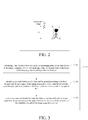
- the horizontal line going through the lowest point of the object to be measured in the image is the straight line where a line segment AB lies.
- a center point of the image is point T.
- the first distance is the vertical distance between the point T and the line segment AB, denoted as d AB .
- the first distance between the horizontal line going through the lowest point of the object to be measured in the image and the horizontal line going through the center point of the image may be obtained in various ways. For a clear layout, this will be described later by way of example.
- a second distance between the object to be measured and the image acquisition device is calculated based on the first distance, an installation height of the image acquisition device and a pitch angle of the image acquisition device.
- the installation height of the image acquisition device refers to a distance between a center point of an imaging plane of an optical lens of the image acquisition device and the ground, denoted as H in FIG. 4 and FIG. 5 .
- the pitch angle of the image acquisition device refers to an angle between a line that goes through the optical center of the optical lens in the image acquisition device and the center point of the imaging plane, and the ground. The pitch angle is denoted as ⁇ EOM in FIG. 4 and FIG. 5 .
- the operation S104 i.e., calculating a second distance between the object to be measured and the image acquisition device based on the first distance, an installation height of the image acquisition device and a pitch of the image acquisition device may include the following operations as shown in FIG. 3 .
- a third distance between a first target point and a center point of the imaging plane is calculated according to the first distance, wherein the first target point is on the imaging plane of the optical lens of the image acquisition device and corresponds to the lowest point.
- an angle between a first line and the ground is calculated according to the third distance and the pitch angle of the image acquisition device, wherein the first line goes through a physical position of the lowest point and the optical center of the optical lens.
- the first line goes through a physical position of the lowest point and the optical center of the optical lens.
- the second line goes through the optical center of the optical lens and the center point of the imaging plane
- d bot is the third distance
- d f is a focal length of the optical lens
- ⁇ is the angle between the first line and the ground
- ⁇ EOM and ⁇ are the pitch angle of the image acquisition device.
- the second distance between the object to be measured and the image acquisition device is calculated according to the angle between the first line and the ground, and the installation height of the image acquisition device.
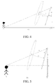
- point P r represents the physical position of the lowest point of the object to be measured
- point O is the optical center of the optical lens
- point E is the center point of the imaging plane
- OE is perpendicular to the imaging plane
- point F (at which the line where P r O lies intersects the imaging plane) is on the imaging plane and corresponds to the lowest point.
- the ground is denoted by a horizontal line where P r Q lies, and FQ is perpendicular to the ground.
- FN in FIG. 4 has a length much less than NQ (i.e., the installation height H of the image acquisition device).
- H, d bot , d f and ⁇ are required to obtain Dis , wherein H, d f and ⁇ may be pre-stored data.
- d f can be easily determined so long as the specification of the optical lens is determined.
- the value of d f may be pre-stored by the user in the image acquisition device.
- the user may use a length measuring tool such as a graduated scale to obtain H , use an angle measuring tool such as a protractor to obtain ⁇ , and then pre-store the obtained H and ⁇ in the image acquisition device.
- the image acquisition device may obtain values of the parameters H , d f and ⁇ pre-stored therein.
- H im and H sensor may also be pre-stored in the image acquisition device.
- the image acquisition device may obtain d bot .
- the image acquisition device may obtain ⁇ according to the obtained d bot .
- the image acquisition device may easily obtain Dis according to the geometrical relationship between ⁇ , H and Dis.
- the second distance may be easily obtained by the image acquisition device with little computation. Accordingly, the image acquisition device can obtain the second distance in a very short period of time. As such, actual demands may be better satisfied.
- the calculation of the second distance between the object to be measured and the image acquisition based on the first distance, the installation height of the image acquisition device and the pitch angle of the image acquisition device is not limited to the above implementation, but may be implemented according to actual needs.
- the embodiment is not limited in this aspect.
- the image acquisition device captures an object to be measured in the image, and obtains a first distance between a horizontal line going through the lowest point of the object to be measured in the image and a horizontal line going through the center point of the image. Then a second distance between the object to be measured and the image acquisition device can be calculated based on the first distance, the installation height of the image acquisition device and the pitch of the image acquisition device.
- an image acquisition device measures a distance based on the first distance, the installation height of the image acquisition device and the pitch angle of the image acquisition device. Therefore, instead of disposing laser emitting and receiving devices and the like in the image acquisition device, only a minor adjustment on the software and hardware in the image acquisition device is required to enable the image acquisition device to perform the operations S101-S104. Accordingly, the image acquisition device may have a less volume than a stereoscopic computer. Therefore, the image acquisition device can measure the distance to an object to be measured while achieving relatively low production cost and easy installation. As a result, actual demands can be better satisfied.
- the method may further include: obtaining a fourth distance between a horizontal line going through a highest point of the object to be measured in the image and the horizontal line going through the center point of the image.
- the method may further include: calculating a height of the object to be measured based on the second distance, the fourth distance, the installation height of the image acquisition device and the pitch angle of the image acquisition device.
- the height of the object to be measured is a distance between the highest point of the object to be measured in the physical scene and the ground, i.e., a vertical distance between point N and P r Q in FIG. 5 .
- the calculation of the height of the object to be measured based on the second distance, the fourth distance, the installation height of the image acquisition device, and the pitch angle of the image acquisition device may be implemented in various manners, examples of which are provided below.
- the calculation of the height of the object to be measured based on the second distance, the fourth distance, the installation height of the image acquisition device, and the pitch of the image acquisition device may include the following operations.
- a fifth distance between a second target point and the center point of the imaging plane is calculated according to the fourth distance, wherein the second target point is on the imaging plane of the optical lens of the image acquisition device and corresponds to the highest point.
- An angle between a third line and the ground is calculated according to the fifth distance and the pitch angle of the image acquisition device, wherein the third line goes through a physical position of the highest point and the optical center of the optical lens.
- the third line goes through a physical position of the highest point and the optical center of the optical lens.
- the fourth line goes through the optical center of the optical lens and the center point of the imaging plane; d top is the fifth distance; d f is a focal length of the optical lens; ⁇ is the angle between the third line and the ground; and ⁇ EOM and ⁇ represent the pitch angle of the image acquisition device.
- the height of the object to be measured is calculated according to the angle between the third line and the ground, the installation height of the image acquisition device, and the second distance.
- point N represents a physical position of the highest point of the object to be measured
- point O is the optical center of the optical lens
- point E is the center point of the imaging plane
- OE is perpendicular to the imaging plane
- point F (at which the line in which NO lies intersects the imaging plane) is on the imaging plane and corresponds to the highest point.
- the ground is represented by a horizontal line where P r Q lies, and FQ is perpendicular to the ground.
- H, Dis, d top , d f and ⁇ are required to obtain h, wherein H, d f and ⁇ may all be pre-stored data.
- d f can be easily determined so long as the specification of the optical lens is determined.
- the value of d f may be pre-stored by a user in the image acquisition device.
- the user may use a length measuring tool such as a graduated scale to obtain H , use an angle measuring tool such as a protractor to obtain ⁇ , and then pre-store the obtained H and ⁇ in the image acquisition device.
- the image acquisition device may obtain d top .
- the image acquisition device may obtain ⁇ according to d top .
- the image acquisition device may easily obtain h according to the geometrical relationship between h, ⁇ , H and Dis .
- a height of an object to be measured may be easily obtained with little computation by the image acquisition device in the manner described above. Accordingly, the image acquisition device can obtain the height of the object to be measured in a very short period of time. As such, actual demands can be better satisfied.
- the obtaining of a fourth distance between a horizontal line going through the highest point of the object to be measured in the image and the horizontal line going through the center point of the image may include:
- the image acquisition device may display an image corresponding to the image data file in a display screen. Subsequently, the image acquisition device may capture an object to be measured in the image, such as the pedestrian shown in FIG. 2 . Once the pedestrian is captured, the image acquisition device may enclose the object to be measured with a target rectangle ABCD.
- the target rectangle ABCD has a side AB and a side CD that are parallel to a horizontal line going through the center point T of the image.
- the point at which the side CD intersects the outer contour of the pedestrian is the highest point of the object to be measured in the image.
- the distance between the side CD and the horizontal line going through the center point T of the image is taken as the fourth distance.
- the obtaining of the first distance between the horizontal line going through the lowest point of the object to be measured in the image and the horizontal line going through the center point of the image may include:
- the image acquisition device may display an image corresponding to the image data file in a display screen. Subsequently, the image acquisition device may capture an object to be measured in the image, such as the pedestrian shown in FIG. 2 . Once the pedestrian is captured, the image acquisition device may enclose the object to be measured with a target rectangle ABCD.
- the target rectangle ABCD has a side AB and a side CD that are parallel to a horizontal line going through the center point T of the image.
- the point at which the side AB intersects the outer contour of the pedestrian is the lowest point of the object to be measured in the image. As such, the distance between the side AB and the horizontal line going the center point T of the image is taken as the first distance.
- the method may further include: processing the image data file to change a bit width of the image data file to a set bit width.
- the set bit width can ensure a normal display of an image corresponding to the image data file on the display screen.
- the preset bit width is, for example, 8bits.
- the image acquisition device has to display the image corresponding to the image data file in the display screen.
- an image data file directly acquired by the image acquisition device typically has a high bit width, for example, 12 bits or 14 bits.
- the display screen has some restrictions to a bit width of an image data file corresponding to an image to be displayed thereon. That is, the display screen requires an image file having a preset bit width (e.g., 8 bits).
- the image acquisition device may process the image data file to change the bit width of the image data file to a preset bit width. In this way, the image corresponding to the image data file can be successfully displayed on the display screen so as to facilitate the subsequent steps.
- a normal display of an image corresponding to the image data file on the display screen can be ensured. This facilitates the performance of the subsequent operations to obtain the second distance and the height of the object to be measured.
- the image acquisition device may be installed on a moving object such as a vehicle.
- the image acquisition device may be installed at the front of the vehicle.
- the pitch angle of the image acquisition device installed at the front of the vehicle changes.
- the image acquisition device will fail to obtain an accurate height of an object to be measured with a preset pitch angle.
- the calculation of the height of the object to be measured based on the second distance, the fourth distance, the installation height and the pitch angle of the image acquisition device may include:
- an electronic compass can be installed on the image acquisition device, through which the amount of change in the pitch angle of the vehicle can be measured.
- the image acquisition device has a pre-stored pitch angle ⁇ EOM
- the electronic compass measures and obtains a pitch angle change of ⁇
- the actual pitch angle of the image acquisition device is a difference between the ⁇ EOM and ⁇ .
- the pitch angle of the image acquisition device may be corrected. For example, the difference between ⁇ EOM and ⁇ is used as the actual pitch angle for the calculation of the height.
- a relatively accurate height of the object to be measured can be obtained by correcting the pitch angle of the image acquisition device.
- the calculation of the second distance between the object to be measured and the image acquisition device based on the first distance, the installation height of the image acquisition device, and the pitch of the image acquisition device includes:
- the detail of the correction on the pitch angle by the image acquisition device can be known with reference to the correction process in the calculation of the height of the object to be measured, and thus is omitted here.
- a relatively accurate second distance can be obtained by correcting the pitch angle of the image acquisition device.
- the image acquisition device in the embodiment of the present disclosure can measure a distance to an object to be measured while achieving relatively low production cost and easy installation. As such, actual needs can be better satisfied.
- FIG. 6 illustrates a block diagram of a measurement apparatus according to an embodiment of the present disclosure.
- the apparatus as shown in FIG. 6 is applicable to an image acquisition device.
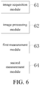
- the apparatus may include an image acquisition module 61, an image processing module 62, a first measurement module 63, and a second measurement module 64.
- the image acquisition module 61 is configured for acquiring image data to generate an image data file.
- the image processing module 62 is configured for capturing an object to be measured in an image corresponding to the image data file.
- the first measurement module 63 is configured for obtaining a first distance between a horizontal line going through a lowest point of the object to be measured in the image and a horizontal line going through a center point of the image.
- the second measurement module 64 is configured for calculating a second distance between the object to be measured and the image acquisition device based on the first distance, an installation height of the image acquisition device and a pitch angle of the image acquisition device.
- an image acquisition device measures a distance based on the first distance, the installation height of the image acquisition device, and the pitch angle of the image acquisition device. Therefore, instead of disposing a laser emitting device, a laser receiving device and the like in the image acquisition device, only a minor adjustment on the software and hardware in the image acquisition device is required. Accordingly, the image acquisition device may have a less volume than a stereoscopic computer. Therefore, the image acquisition device can measure the distance to an object to be measured while achieving relatively low production cost and easy installation. As a result, actual demands can be better satisfied.
- the second measurement module may include:
- the apparatus may further include:
- the fourth measurement module may include:
- the third measurement module may include:
- the apparatus may further include: a bit width change module configured for processing, before the object to be measured in the image corresponding to the image data file is captured, the image data file, so as to change a bit with of the image data file to a set bit width.
- a bit width change module configured for processing, before the object to be measured in the image corresponding to the image data file is captured, the image data file, so as to change a bit with of the image data file to a set bit width.
- the fourth measurement module may include:
- the first measurement module may include:
- the second measurement module may include:
- the apparatus may further include: an alarm module configured for outputting an alarm signal when the second distance is smaller than a preset distance threshold.
- the image acquisition device may be installed on a vehicle.
- the image acquisition may issue an alarm signal, for example, an acoustical signal.
- a passenger on the vehile may be aware of the situation in time and make a proper response. As such, the security of the vehicle and pedestrian may be guaranteed.
- the apparatus may further include: a display module configured for displaying, in the image, the second distance and the height of the object to be measured.
- the height and distance information of an object to be measured may be obtained by the user intuitively and conveniently through contents displayed in the image. The user may thus have a better experience.
- the image acquisition device in the embodiment can measure the distance to an object to be measured while achieving relatively low production cost and easy installation. As a result, actual demands can be better satisfied.
- a storage medium provided by an embodiment of the present disclosure is described below.
- the embodiment of the present application provides a storage medium for storing an executable program code which, when executed, performs the measurement method described above.
- the image acquisition device in the embodiment can measure the distance to an object to be measured while achieving relatively low production cost and easy installation. As a result, actual demands can be better satisfied.
- the embodiment of the present application provides an application program which performs, when executed, the measurement method described above.
- the image acquisition device in the embodiment can measure the distance to an object to be measured while achieving relatively low production cost and easy installation. As a result, actual demands can be better satisfied.
- the embodiment of the present disclosure provides an image acquisition device, including:
- the image acquisition device in the embodiment can measure the distance to an object to be measured while achieving relatively low production cost and easy installation. As a result, actual demands can be better satisfied.
Landscapes
- Engineering & Computer Science (AREA)
- Physics & Mathematics (AREA)
- General Physics & Mathematics (AREA)
- Radar, Positioning & Navigation (AREA)
- Remote Sensing (AREA)
- Electromagnetism (AREA)
- Computer Vision & Pattern Recognition (AREA)
- Theoretical Computer Science (AREA)
- Multimedia (AREA)
- Length Measuring Devices By Optical Means (AREA)
- Measurement Of Optical Distance (AREA)
Abstract
Description
- The present application claims the priority to a Chinese patent application No.
201610669751.1 - The present disclosure relates to the field of video monitoring, and particularly to a measurement method and apparatus.
- With the rapid development of science and technology, more demands are placed on the functionality of an image acquisition device, such as a camera. For example, an image acquisition device capable of automatically identifying a distance to a captured object is desired. For the purpose above, approaches have been proposed in the relevant art. A Chinese patent application
CN100388760 entitled "Ranging Digital Camera" proposes a camera having a laser ranging device installed thereon, through which a distance is measured. A Chinese patent applicationCN203813888 entitled "A Vehicle Ranging Module with Dual Cameras" proposes to shoot by a stereo camera, such that a distance can be measured, by stereoscopic vision technology, through the stereo camera. - However, the two approaches both bear some deficiencies in distance measuring. For the former, the requirement of a laser emitting device and a laser receiving device in the camera may increase the production cost of a camera. For the latter, the installation of a stereo camera may be troublesome due to a typically large volume thereof.
- Therefore, how to enable an image acquisition device to measure a distance while achieving lower production cost and easy installation is an urgent problem to be solved.
- Embodiments of the present disclosure provide a measurement method and apparatus, to enable an image acquisition device to measure a distance while ensuring the lower production cost and easy installation of the image acquisition device.
- An embodiment of the present application provides a measurement method applicable to an image acquisition device. The method includes:
- acquiring image data to generate an image data file;
- capturing an object to be measured in an image corresponding to the image data file;
- obtaining a first distance between a horizontal line going through a lowest point of the object to be measured in the image and a horizontal line going through a center point of the image; and
- calculating a second distance between the object to be measured and the image acquisition device based on the first distance, an installation height of the image acquisition device and a pitch angle of the image acquisition device.
- In one implementation of the embodiment of the present application, calculating a second distance between the object to be measured and the image acquisition device based on the first distance, an installation height of the image acquisition device and a pitch angle of the image acquisition device includes:
- calculating a third distance between a first target point and a center point of an imaging plane according to the first distance, wherein the first target point is on the imaging plane of an optical lens of the image acquisition device and corresponds to the lowest point;
- calculating an angle between a first line and the ground according to the third distance and the pitch angle of the image acquisition device, wherein the first line goes through a physical position of the lowest point and an optical center of the optical lens; and
- calculating the second distance between the object to be measured and the image acquisition device according to the angle between the first line and the ground, and the installation height of the image acquisition device.
- In one implementation of the embodiment of the present application, after capturing an object to be measured in an image corresponding to the image data file, the method further includes:
- obtaining a fourth distance between a horizontal line going through a highest point of the object to be measured in the image and the horizontal line going through the center point of the image; and
- after calculating the second distance between the object to be measured and the image acquisition device, the method further includes:
calculating a height of the object to be measured based on the second distance, the fourth distance, the installation height of the image acquisition device, and the pitch angle of the image acquisition device. - In one implementation of the embodiment of the present application, calculating a height of the object to be measured based on the second distance, the fourth distance, the installation height of the image acquisition device, and the pitch angle of the image acquisition device includes:
- calculating a fifth distance between a second target point and a center point of an imaging plane according to the fourth distance, wherein the second target point is on the imaging plane of an optical lens of the image acquisition device and corresponds to the highest point;
- calculating an angle between a third line and the ground according to the fifth distance and the pitch angle of the image acquisition device, wherein the third line goes through a physical position of the highest point and an optical center of the optical lens; and
- calculating the height of the object to be measured according to the angle between the third line and the ground, the installation height of the image acquisition device, and the second distance.
- In one implementation of the embodiment of the present application, obtaining a fourth distance between a horizontal line going through a highest point of the object to be measured in the image and the horizontal line going through the center point of the image includes:
- enclosing the object to be measured with a target rectangle, the target rectangle having a pair of sides parallel to the horizontal line going through the center point of the image, and being a rectangle with a minimum area among rectangles that can enclose the object to be measured; and
- taking a distance between a side of the pair of sides that is farther from the ground and the horizontal line going through the center point of the image as the fourth distance.
- In one specific implementation of the embodiment of the present application, before capturing an object to be measured in an image corresponding to the image data file, the method further includes:
processing the image data file to change a bit width of the image data file to a set bit width. - In one implementation of the embodiment of the present application, calculating a height of the object to be measured based on the second distance, the fourth distance, the installation height of the image acquisition device, and the pitch angle of the image acquisition device includes:
- detecting whether the pitch angle of the image acquisition device changes;
- if the pitch angle of the image acquisition device changes, correcting the pitch angle of the image acquisition device; and
- calculating the height of the object to be measured based on the second distance, the fourth distance, the installation height of the image acquisition device, and the corrected pitch angle of the image acquisition device.
- In one implementation of the embodiment of the present application, obtaining a first distance between a horizontal line going through the lowest point of the object to be measured in the image and a horizontal line going through a center point of the image includes:
- enclosing the object to be measured with a target rectangle, the target rectangle having a pair of sides parallel to the horizontal line going through the center point of the image and being a rectangle with a minimum area among rectangles that can enclose the object to be measured; and
- taking a distance between a side of the pair of sides that is closer to the ground and the horizontal line going through the center point of the image as the first distance.
- In one implementation of the embodiment of the present application, calculating a second distance between the object to be measured and the image acquisition device based on the first distance, an installation height of the image acquisition device and a pitch angle of the image acquisition device includes:
- detecting whether the pitch angle of the image acquisition device changes;
- if the pitch angle of the image acquisition device changes, correcting the pitch angle of the image acquisition device; and
- calculating the second distance between the object to be measured and the image acquisition device based on the first distance, the installation height of the image acquisition device, and the corrected pitch angle of the image acquisition device.
- An embodiment of the present disclosure provides a measurement apparatus applicable to an image acquisition device. The apparatus includes:
- an image acquisition module configured for acquiring image data to generate an image data file;
- an image processing module configured for capturing an object to be measured in an image corresponding to the image data file;
- a first measurement module configured for obtaining a first distance between a horizontal line going through a lowest point of the object to be measured in the image and a horizontal line going through a center point of the image; and
- a second measurement module configured for calculating a second distance between the object to be measured and the image acquisition device based on the first distance, an installation height of the image acquisition device and a pitch angle of the image acquisition device.
- In one implementation of the embodiment of the present application, the second measurement module includes:
- a first calculating unit configured for calculating a third distance between a first target point and a center point of an imaging plane according to the first distance, wherein the first target point is on the imaging plane of an optical lens of the image acquisition device and corresponds to the lowest point;
- a second calculating unit configured for calculating an angle between a first line and the ground according to the third distance and the pitch angle of the image acquisition device, wherein the first line goes through a physical position of the lowest point and an optical center of the optical lens; and
- a third calculating unit configured for calculating the second distance between the object to be measured and the image acquisition device according to the angle between the first line and the ground, and the installation height of the image acquisition device.
- In one implementation of the embodiment of the present application, the apparatus further includes:
- a third measurement module configured for obtaining, after the object to be measured in the image corresponding to the image data file is captured, a fourth distance between a horizontal line going through a highest point of the object to be measured in the image and the horizontal line going through the center point of the image; and
- a fourth measurement module configured for calculating, after the second distance between the object to be measured and the image acquisition device is calculated, a height of the object to be measured based on the second distance, the fourth distance, the installation height of the image acquisition device, and the pitch angle of the image acquisition device.
- In one implementation of the embodiment of the present application, the fourth measurement module includes:
- a fourth calculating unit configured for calculating a fifth distance between a second target point and a center point of an imaging plane according to the fourth distance, wherein the second target point is on the imaging plane of an optical lens of the image acquisition device and corresponds to the highest point;
- a fifth calculating unit configured for calculating an angle between a third line and the ground according to the fifth distance and the pitch angle of the image acquisition device, wherein the third line goes through a physical position of the highest point and an optical center of the optical lens; and
- a sixth calculating unit configured for calculating the height of the object to be measured according to the angle between the third line and the ground, the installation height of the image acquisition device, and the second distance.
- In one implementation of the embodiment of the present application, the third measurement module includes:
- a first to-be-measured object processing unit configured for enclosing the object to be measured with a target rectangle, the target rectangle having a pair of sides parallel to the horizontal line going through the center point of the image, and being a rectangle with a minimum area among rectangles that can enclose the object to be measured; and
- a first distance determining unit configured for taking a distance between a side of the pair of sides that is farther from the ground and the horizontal line going through the center point of the image as the fourth distance.
- In one implementation of the embodiment of the present application, the apparatus further includes:
a bit width change module configured for processing, before the object to be measured in the image corresponding to the image data file is captured, the image data file, so as to change a bit with of the image data file to a set bit width. - In one implementation of the embodiment of the present application, the fourth measurement module includes:
- a first pitch angle detecting unit configured for detecting, before the height of the object to be measured is calculated, whether the pitch angle of the image acquisition device changes;
- a first pitch angle correcting unit configured for correcting the pitch angle of the image acquisition device when the pitch angle of the image acquisition device changes; and
- a height calculating unit configured for calculating the height of the object to be measured based on the second distance, the fourth distance, the installation height of the image acquisition device, and the corrected pitch angle of the image acquisition device.
- In one implementation of the embodiment of the present application, the first measurement module includes:
- a second to-be-measured object processing unit configured for enclosing the object to be measured with a target rectangle, the target rectangle having a pair of sides parallel to the horizontal line going through the center point of the image and being a rectangle with a minimum area among rectangles that can enclose the object to be measured; and
- a second distance determining unit configured for taking a distance between a side of the pair of sides that is closer to the ground and the horizontal line going through the center point of the image as the first distance.
- In one implementation of the embodiment of the present application, the second measurement module includes:
- a second pitch angle detecting unit configured for detecting, before the second distance between the object to be measured and the image acquisition device is calculated, whether the pitch angle of the image acquisition device changes;
- a second pitch angle correcting unit configured for correcting the pitch angle of the image acquisition device when the pitch angle of the image acquisition device changes; and
- a distance calculating unit configured for calculating the second distance between the object to be measured and the image acquisition device based on the first distance, the installation height of the image acquisition device, and the corrected pitch angle of the image acquisition device.
- In one implementation of the embodiment of the present application, the apparatus further includes:
an alarm module configured for outputting an alarm signal when the second distance is smaller than a preset distance threshold. - In one implementation of the embodiment of the present application, the apparatus further includes:
a display module configured for displaying, in the image, the second distance and the height of the object to be measured. - An embodiment of the present disclosure provides a storage medium for storing an executable program code which, when executed, performs the measurement method described above.
- An embodiment of the present disclosure provides an application program which performs, when executed, the measurement method described above.
- An embodiment of the present disclosure provides an image acquisition device, including:
- a processor, a memory, a communication interface and a bus, wherein
- the processor, the memory and the communication interface connect and communicate with each other via the bus;
- the memory is configured for storing an executable program code;
- the processor is configured for executing a program corredponding to the executable program code by reading the executable program code stored in the memory, so as to perform the operations including:
- acquiring image data to generate an image data file;
- capturing an object to be measured in an image corresponding to the image data file;
- obtaining a first distance between a horizontal line going through a lowest point of the object to be measured in the image and a horizontal line going through a center point of the image; and
- calculating a second distance between the object to be measured and the image acquisition device based on the first distance, an installation height of the image acquisition device and a pitch angle of the image acquisition device.
- Embodiments of the present disclosure provide a measurement method and apparatus. The method is applicable to the image acquisition device. The method includes: acquiring image data to generate an image data file; capturing an object to be measured in an image corresponding to the image data file; obtaining a first distance between a horizontal line going through a lowest point of the object to be measured in the image and a horizontal line going through a center point of the image; and calculating a second distance between the object to be measured and the image acquisition device based on the first distance, an installation height of the image acquisition device and a pitch angle of the image acquisition device. Unlike the relevant art where the laser ranging technology or stereoscopic vision technology is utilized for distance measurement, an image acquisition device according to the embodiment measures a distance based on the first distance, the installation height of the image acquisition device, and the pitch angle of the image acquisition device. Therefore, instead of disposing a laser emitting device, a laser receiving device and the like in the image acquisition device, only a minor adjustment on the software and hardware in the image acquisition device is required to enable the image acquisition device to perform the operations described above. Accordingly, the image acquisition device may have a less volume than a stereoscopic computer. Therefore, the image acquisition device can measure the distance to an object to be measured while achieving relatively low production cost and easy installation. As a result, actual demands can be better satisfied.
- The features and advantages of the present disclosure will be more clearly understood with reference to accompanying drawings. The drawings are intended to be exemplary and should not be construed as limiting the present disclosure. In the drawings:
-
FIG. 1 is a flow chart of a measurement method provided by an embodiment of the present application; -
FIG. 2 is a schematic illustrating a displayed image on a display screen; -
FIG. 3 is a flow chart showing the details of S104 inFIG. 1 ; -
FIG. 4 is a schematic diagram of a photo shooting by an image acquisition device; -
FIG. 5 is another schematic diagram of a photo shooting by an image acquisition device; and -
FIG. 6 is a block diagram of a measurement apparatus provided by an embodiment of the present disclosure. - To simplify the operations of unfolding a folder with a higher efficiency and better user experience, embodiments of the present application provide a method and apparatus for unfolding a folder.
- Technical solutions in the embodiments of the present application are clearly and completely described below with reference to the accompanying drawings in the embodiments of the present application. Obviously, the described embodiments are merely a part of, but not all, the embodiments of the present application. All other embodiments obtained without creative efforts in view of the embodiments of the present application by those skilled in the art fall within the scope of the present application.
- To solve the problems existing in relevant art, embodiments of the present application provide a measurement method and apparatus.
- An introduction to the measurement method according to an embodiment of the present disclosure is first provided below.
- It should be noted that the measurement method provided by the embodiment of the present disclosure can be applied to an image acquisition device. In a practical application, the image acquisition device may be a camera, such as a monocular camera. Of course, the image acquisition device may also be other types of devices capable of acquiring images. Specific types of the image acquisition device are not limited in embodiments of the present application.
- Referring to
FIG. 1 , a flow chart of a measurement method according to an embodiment of the present application is illustrated. As shown inFIG. 1 , the measurement method may include the following operations. - At S101, image data is acquired to generate an image data file.
- An image acquisition device may acquire an optical signal for a scene being shot, and then convert the acquired optical signal into an image signal. The image signal may constitute image data. The electronic device may then generate an image data file according to the image data.
- At S102, an object to be measured in an image corresponding to the image data file is captured.
- Specifically, the object to be measured may be a pedestrian, a vehicle, or the like. Of course, the types of the object to be measured are not limited thereto and may be determined according to actual conditions. The embodiment is not limited in this aspect.
- In the present embodiment, specifically, the object to be measured in an image corresponding to the image data file may be captured through a Histogram of Oriented Gradient (HOG) and Support Vector Machine (SVM) method.
- It should be appreciated that, HOG is a feature descriptor used in computer vision and image processing for object detection. In the technique, a gradient-orientation histogram for a localized portion of an image is calculated and obtained to serve as a feature. SVM is a supervised learning model in the field of machine learning and is typically used for pattern recognition, classification, and regression analysis.
- Specifically, the HOG and SVM method may include the following operations:
- A. Sample build: a set of positive samples and negative samples of image is built, which meets the requirements of a HOG descriptor.
- B. Feature extraction: a batch of features is extracted from the built set of positive samples and negative samples using a HOG descriptor, so as to build a set of feature samples.
- C. SVM model: an SVM model with a penalty-like factor is built.
- D. Classifier training: a supervised training is performed on the SVM using the set of feature samples.
- E. Target detection: target detection is performed on a sequence of videos using a HOG description-based target detection method.
- After the application of the HOG and SVM method described above, the object to be measured in the image corresponding to the image data file can be finally captured.
- It should be appreciated that, implementations for the capture of an object to be measured in the image corresponding to the image data file are not limited thereto, but may also be implemented in other manners, the details of which are omitted in this embodiment.
- At S103, a first distance between a horizontal line going through a lowest point of the object to be measured in the image and a horizontal line going through a center point of the image is obtained.
- As shown in
FIG. 2 , assuming that the lowest point of the object to be measured in the image is point A or point B (points A and B are on the same horizontal line), the horizontal line going through the lowest point of the object to be measured in the image is the straight line where a line segment AB lies. A center point of the image is point T. Accordingly, the first distance is the vertical distance between the point T and the line segment AB, denoted as dAB. - It is noted that the first distance between the horizontal line going through the lowest point of the object to be measured in the image and the horizontal line going through the center point of the image may be obtained in various ways. For a clear layout, this will be described later by way of example.
- At S104, a second distance between the object to be measured and the image acquisition device is calculated based on the first distance, an installation height of the image acquisition device and a pitch angle of the image acquisition device.
- It should be noted that the installation height of the image acquisition device refers to a distance between a center point of an imaging plane of an optical lens of the image acquisition device and the ground, denoted as H in
FIG. 4 and FIG. 5 . The pitch angle of the image acquisition device refers to an angle between a line that goes through the optical center of the optical lens in the image acquisition device and the center point of the imaging plane, and the ground. The pitch angle is denoted as ∠EOM inFIG. 4 and FIG. 5 . - In an implementation of the embodiment of the present application, the operation S104, i.e., calculating a second distance between the object to be measured and the image acquisition device based on the first distance, an installation height of the image acquisition device and a pitch of the image acquisition device may include the following operations as shown in
FIG. 3 . - At S1041, a third distance between a first target point and a center point of the imaging plane is calculated according to the first distance, wherein the first target point is on the imaging plane of the optical lens of the image acquisition device and corresponds to the lowest point.
- Specifically, the third distance may be calculated according to the first distance through the following formula:

- At S1042, an angle between a first line and the ground is calculated according to the third distance and the pitch angle of the image acquisition device, wherein the first line goes through a physical position of the lowest point and the optical center of the optical lens.
- Specifically, the angle between the first line and the ground may be calculated according to the third distance and the pitch of the image acquisition device through the following formula:

- At S1043, the second distance between the object to be measured and the image acquisition device is calculated according to the angle between the first line and the ground, and the installation height of the image acquisition device.
- Specifically, the second distance may be calculated according to the angle between the first line and the ground, and the installation height of the image acquisition device through the following formula:

- The principle behind the calculation of the second distance is now described below with reference to
FIG. 4 . - As shown in
FIG. 4 , point Pr represents the physical position of the lowest point of the object to be measured, point O is the optical center of the optical lens, point E is the center point of the imaging plane, OE is perpendicular to the imaging plane, and point F (at which the line where PrO lies intersects the imaging plane) is on the imaging plane and corresponds to the lowest point. The ground is denoted by a horizontal line where PrQ lies, and FQ is perpendicular to the ground. - The following formulas can be easily derived from the geometric relationship in
FIG. 4 :
- In general, FN in
FIG. 4 has a length much less than NQ (i.e., the installation height H of the image acquisition device). As such, FQ may be assumed to be approximately equal to H. Accordingly,
- In the present embodiment, H, dbot, df and α are required to obtain Dis, wherein H, df and α may be pre-stored data. Specifically, df can be easily determined so long as the specification of the optical lens is determined. The value of df may be pre-stored by the user in the image acquisition device. Regarding H and α, after installing the image acquisition device, the user may use a length measuring tool such as a graduated scale to obtain H, use an angle measuring tool such as a protractor to obtain α, and then pre-store the obtained H and α in the image acquisition device. As such, when the second distance is to be calculated, the image acquisition device may obtain values of the parameters H, df and α pre-stored therein. As for dbot , it cannot be pre-stored, but it can be determined according to the following formula:

- As such, after the first distance dAB is obtained, the image acquisition device may obtain dbot. Next, the image acquisition device may obtain β according to the obtained dbot. Next, the image acquisition device may easily obtain Dis according to the geometrical relationship between β, H and Dis.
- As shown, in the manner described above, the second distance may be easily obtained by the image acquisition device with little computation. Accordingly, the image acquisition device can obtain the second distance in a very short period of time. As such, actual demands may be better satisfied.
- It should be appreciated that, the calculation of the second distance between the object to be measured and the image acquisition based on the first distance, the installation height of the image acquisition device and the pitch angle of the image acquisition device is not limited to the above implementation, but may be implemented according to actual needs. The embodiment is not limited in this aspect.
- It is readily apparent that, in this embodiment, after obtaining an image data file, the image acquisition device captures an object to be measured in the image, and obtains a first distance between a horizontal line going through the lowest point of the object to be measured in the image and a horizontal line going through the center point of the image. Then a second distance between the object to be measured and the image acquisition device can be calculated based on the first distance, the installation height of the image acquisition device and the pitch of the image acquisition device.
- Unlike the relevant art where the laser ranging technology or stereoscopic vision technology is utilized for distance measurement, an image acquisition device according to the embodiment measures a distance based on the first distance, the installation height of the image acquisition device and the pitch angle of the image acquisition device. Therefore, instead of disposing laser emitting and receiving devices and the like in the image acquisition device, only a minor adjustment on the software and hardware in the image acquisition device is required to enable the image acquisition device to perform the operations S101-S104. Accordingly, the image acquisition device may have a less volume than a stereoscopic computer. Therefore, the image acquisition device can measure the distance to an object to be measured while achieving relatively low production cost and easy installation. As a result, actual demands can be better satisfied.
- In an implementation of the embodiment of the present application, after the object to be measured in the image corresponding to the image data file is captured, the method may further include:
obtaining a fourth distance between a horizontal line going through a highest point of the object to be measured in the image and the horizontal line going through the center point of the image. - Accordingly, after the second distance between the object to be measured and the image acquisition device is calculated, the method may further include:
calculating a height of the object to be measured based on the second distance, the fourth distance, the installation height of the image acquisition device and the pitch angle of the image acquisition device. - The height of the object to be measured is a distance between the highest point of the object to be measured in the physical scene and the ground, i.e., a vertical distance between point N and PrQ in
FIG. 5 . - It should be noted that, the calculation of the height of the object to be measured based on the second distance, the fourth distance, the installation height of the image acquisition device, and the pitch angle of the image acquisition device may be implemented in various manners, examples of which are provided below.
- In this embodiment, the calculation of the height of the object to be measured based on the second distance, the fourth distance, the installation height of the image acquisition device, and the pitch of the image acquisition device may include the following operations.
- A fifth distance between a second target point and the center point of the imaging plane is calculated according to the fourth distance, wherein the second target point is on the imaging plane of the optical lens of the image acquisition device and corresponds to the highest point.
- Specifically, the fifth distance may be calculated according to the fourth distance through the following formula:

- An angle between a third line and the ground is calculated according to the fifth distance and the pitch angle of the image acquisition device, wherein the third line goes through a physical position of the highest point and the optical center of the optical lens.
- Specifically, the angle between the third line and the ground may be calculated according to the fifth distance and the pitch angle of the image acquisition device through the following formula:

- The height of the object to be measured is calculated according to the angle between the third line and the ground, the installation height of the image acquisition device, and the second distance.
- Specifically, the height of the object to be measured may be calculated according to the angle between the third line and the ground, and the second distance through the following formula:

- The principle behind the calculation of the height of the object to be measured will be described below with reference to
FIG. 5 . - As shown in
FIG. 5 , point N represents a physical position of the highest point of the object to be measured, point O is the optical center of the optical lens, point E is the center point of the imaging plane, OE is perpendicular to the imaging plane, and point F (at which the line in which NO lies intersects the imaging plane) is on the imaging plane and corresponds to the highest point. The ground is represented by a horizontal line where PrQ lies, and FQ is perpendicular to the ground. - The following formula may be easily derived from the geometric relationship in
FIG. 5 :
- In general, in
Fig. 5 , FP has a length much less than PQ (i.e., the installation height H of the image acquisition device). FQ may be thus considered to be approximately equal to H. Accordingly, h = H - Dis · tan β. - In the present embodiment, H, Dis, dtop, df and α are required to obtain h, wherein H, df and α may all be pre-stored data. Specifically, df can be easily determined so long as the specification of the optical lens is determined. The value of df may be pre-stored by a user in the image acquisition device. Regarding H and α, after installing the image acquisition device, the user may use a length measuring tool such as a graduated scale to obtain H, use an angle measuring tool such as a protractor to obtain α, and then pre-store the obtained H and α in the image acquisition device. As such, when a height of the object to be measured is to be calculated, the image acquisition device may obtain values of parameters H, df , α and the like pre-stored therein. Dis may be obtained according to the first distance through a predefined distance calculation formula. As for dtop , it cannot be pre-stored, but it can be determined according to the following formula:

- As such, after obtaining the fourth distance dDC, the image acquisition device may obtain dtop. Next, the image acquisition device may obtain β according to dtop. Next, the image acquisition device may easily obtain h according to the geometrical relationship between h, β, H and Dis.
- It can be seen that, a height of an object to be measured may be easily obtained with little computation by the image acquisition device in the manner described above. Accordingly, the image acquisition device can obtain the height of the object to be measured in a very short period of time. As such, actual demands can be better satisfied.
- In one implementation of the embodiment of the present application, the obtaining of a fourth distance between a horizontal line going through the highest point of the object to be measured in the image and the horizontal line going through the center point of the image may include:
- enclosing the object to be measured with a target rectangle, which has a pair of sides parallel to a horizontal line going through the center of the image, wherein the target rectangle is a rectangle with a minimum area among rectangles that can enclose the object to be measured;
- taking a distance between a side of the pair of sides that is farther from the ground and the horizontal line going through the center point of the image as the fourth distance.
- As shown in
FIG. 2 , after acquiring image data and generating an image data file, the image acquisition device may display an image corresponding to the image data file in a display screen. Subsequently, the image acquisition device may capture an object to be measured in the image, such as the pedestrian shown inFIG. 2 . Once the pedestrian is captured, the image acquisition device may enclose the object to be measured with a target rectangle ABCD. The target rectangle ABCD has a side AB and a side CD that are parallel to a horizontal line going through the center point T of the image. As can be readily seen, the point at which the side CD intersects the outer contour of the pedestrian is the highest point of the object to be measured in the image. As such, the distance between the side CD and the horizontal line going through the center point T of the image is taken as the fourth distance. - It can be seen that the fourth distance can be conveniently obtained in the above manner.
- In one implementation of the embodiment of the present disclosure, the obtaining of the first distance between the horizontal line going through the lowest point of the object to be measured in the image and the horizontal line going through the center point of the image may include:
- enclosing the object to be measured with a target rectangle, which has a pair of sides parallel to the horizontal line going through the center point of the image, wherein the target rectangle is a rectangle with a minimum area among rectangles that can enclose the object;
- taking the distance between a side of the pair of sides that is closer to the ground and the horizontal line going through the center point of the image as the first distance.
- As shown in
FIG. 2 , after acquiring image data and generating an image data file, the image acquisition device may display an image corresponding to the image data file in a display screen. Subsequently, the image acquisition device may capture an object to be measured in the image, such as the pedestrian shown inFIG. 2 . Once the pedestrian is captured, the image acquisition device may enclose the object to be measured with a target rectangle ABCD. The target rectangle ABCD has a side AB and a side CD that are parallel to a horizontal line going through the center point T of the image. As can be readily seen, the point at which the side AB intersects the outer contour of the pedestrian is the lowest point of the object to be measured in the image. As such, the distance between the side AB and the horizontal line going the center point T of the image is taken as the first distance. - It can be seen that the first distance can be conveniently obtained in the above manner.
- In one implementation of the embodiment of the present disclosure, before the object to be measured in the image corresponding to the image data file is captured, the method may further include:
processing the image data file to change a bit width of the image data file to a set bit width. - It is noted that the set bit width can ensure a normal display of an image corresponding to the image data file on the display screen. The preset bit width is, for example, 8bits.
- As can be readily seen, to determine the first distance and the fourth distance with a target rectangle, the image acquisition device has to display the image corresponding to the image data file in the display screen. In the embodiment, an image data file directly acquired by the image acquisition device typically has a high bit width, for example, 12 bits or 14 bits. However, the display screen has some restrictions to a bit width of an image data file corresponding to an image to be displayed thereon. That is, the display screen requires an image file having a preset bit width (e.g., 8 bits). In the embodiment, before capturing the object to be measured in the image corresponding to the image data file, the image acquisition device may process the image data file to change the bit width of the image data file to a preset bit width. In this way, the image corresponding to the image data file can be successfully displayed on the display screen so as to facilitate the subsequent steps.
- It can be seen that, in the embodiment, a normal display of an image corresponding to the image data file on the display screen can be ensured. This facilitates the performance of the subsequent operations to obtain the second distance and the height of the object to be measured.
- It may be appreciated that, in some cases, the image acquisition device may be installed on a moving object such as a vehicle. Specifically, the image acquisition device may be installed at the front of the vehicle. When the front wheel of the vehicle goes past a pit on the ground, the pitch angle of the image acquisition device installed at the front of the vehicle changes. At this time, the image acquisition device will fail to obtain an accurate height of an object to be measured with a preset pitch angle. In order to solve the problem, in this embodiment, the calculation of the height of the object to be measured based on the second distance, the fourth distance, the installation height and the pitch angle of the image acquisition device may include:
- detecting whether the pitch angle of the image acquisition device changes;
- if so, correcting the pitch angle of the image acquisition device;
- calculating the height of the object to be measured based on the second distance, the fourth distance, the installation height of the image acquisition device, and the corrected pitch angle of the image acquisition device.
- In this embodiment, an electronic compass can be installed on the image acquisition device, through which the amount of change in the pitch angle of the vehicle can be measured. Assuming that the image acquisition device has a pre-stored pitch angle ∠EOM, and the electronic compass measures and obtains a pitch angle change of γ, then the actual pitch angle of the image acquisition device is a difference between the ∠EOM and γ. In actual calculation of the height of the object to be measured, the pitch angle of the image acquisition device may be corrected. For example, the difference between ∠EOM and γ is used as the actual pitch angle for the calculation of the height.
- It can be seen that, in the embodiment, a relatively accurate height of the object to be measured can be obtained by correcting the pitch angle of the image acquisition device.
- Similarly, in this embodiment, the calculation of the second distance between the object to be measured and the image acquisition device based on the first distance, the installation height of the image acquisition device, and the pitch of the image acquisition device includes:
- detecting whether the pitch angle of the image acquisition device changes;
- if so, correcting the pitch angle of the image acquisition device; and
- calculating the second distance between the object to be measured and the image acquisition device based on the first distance, the installation height of the image acquisition device, and the corrected pitch angle of the image acquisition device.
- The detail of the correction on the pitch angle by the image acquisition device can be known with reference to the correction process in the calculation of the height of the object to be measured, and thus is omitted here.
- It can be seen that, in the embodiment, a relatively accurate second distance can be obtained by correcting the pitch angle of the image acquisition device.
- In summary, the image acquisition device in the embodiment of the present disclosure can measure a distance to an object to be measured while achieving relatively low production cost and easy installation. As such, actual needs can be better satisfied.
- In correspondence with the above method embodiment, an embodiment of the present disclosure provides a measurement apparatus.
FIG. 6 illustrates a block diagram of a measurement apparatus according to an embodiment of the present disclosure. The apparatus as shown inFIG. 6 is applicable to an image acquisition device. The apparatus may include animage acquisition module 61, animage processing module 62, afirst measurement module 63, and asecond measurement module 64. - The
image acquisition module 61 is configured for acquiring image data to generate an image data file. - The
image processing module 62 is configured for capturing an object to be measured in an image corresponding to the image data file. - The
first measurement module 63 is configured for obtaining a first distance between a horizontal line going through a lowest point of the object to be measured in the image and a horizontal line going through a center point of the image. - The
second measurement module 64 is configured for calculating a second distance between the object to be measured and the image acquisition device based on the first distance, an installation height of the image acquisition device and a pitch angle of the image acquisition device. - Unlike the relevant art where laser ranging technology or stereoscopic vision technology is utilized for distance measurement, an image acquisition device according to the embodiment measures a distance based on the first distance, the installation height of the image acquisition device, and the pitch angle of the image acquisition device. Therefore, instead of disposing a laser emitting device, a laser receiving device and the like in the image acquisition device, only a minor adjustment on the software and hardware in the image acquisition device is required. Accordingly, the image acquisition device may have a less volume than a stereoscopic computer. Therefore, the image acquisition device can measure the distance to an object to be measured while achieving relatively low production cost and easy installation. As a result, actual demands can be better satisfied.
- In one implementation of the embodiment of the present application, the second measurement module may include:
- a first calculating unit configured for calculating a third distance between a first target point and a center point of an imaging plane according to the first distance, wherein the first target point is on the imaging plane of an optical lens of the image acquisition device and corresponds to the lowest point;
- a second calculating unit configured for calculating an angle between a first line and the ground according to the third distance and the pitch angle of the image acquisition device, wherein the first line goes through a physical position of the lowest point and an optical center of the optical lens; and
- a third calculating unit configured for calculating the second distance between the object to be measured and the image acquisition device according to the angle between the first line and the ground, and the installation height of the image acquisition device.
- In one implementation of the embodiment of the present application, the apparatus may further include:
- a third measurement module configured for obtaining, after the object to be measured in the image corresponding to the image data file is captured, a fourth distance between a horizontal line going through a highest point of the object to be measured in the image and the horizontal line going through the center point of the image; and
- a fourth measurement module configured for calculating, after the second distance between the object to be measured and the image acquisition device is calculated, a height of the object to be measured based on the second distance, the fourth distance, the installation height of the image acquisition device, and the pitch angle of the image acquisition device.
- In one implementation of the embodiment of the present application, the fourth measurement module may include:
- a fourth calculating unit configured for calculating a fifth distance between a second target point and a center point of an imaging plane according to the fourth distance, wherein the second target point is on the imaging plane of an optical lens of the image acquisition device and corresponds to the highest point;
- a fifth calculating unit configured for calculating an angle between a third line and the ground according to the fifth distance and the pitch angle of the image acquisition device, wherein the third line goes through a physical position of the highest point and an optical center of the optical lens; and
- a sixth calculating unit configured for calculating the height of the object to be measured according to the angle between the third line and the ground, the installation height of the image acquisition device, and the second distance.
- In one implementation of the embodiment of the present application, the third measurement module may include:
- a first to-be-measured object processing unit configured for enclosing the object to be measured with a target rectangle, the target rectangle having a pair of sides parallel to the horizontal line going through the center point of the image, and being a rectangle with a minimum area among rectangles that can enclose the object to be measured; and
- a first distance determining unit configured for taking a distance between a side of the pair of sides that is farther from the ground and the horizontal line going through the center point of the image as the fourth distance.
- In one implementation of the embodiment of the present application, the apparatus may further include:
a bit width change module configured for processing, before the object to be measured in the image corresponding to the image data file is captured, the image data file, so as to change a bit with of the image data file to a set bit width. - In one implementation of the embodiment of the present application, the fourth measurement module may include:
- a first pitch angle detecting unit configured for detecting, before the height of the object to be measured is calculated, whether the pitch angle of the image acquisition device changes;
- a first pitch angle correcting unit configured for correcting the pitch angle of the image acquisition device when the pitch angle of the image acquisition device changes; and
- a height calculating unit configured for calculating the height of the object to be measured based on the second distance, the fourth distance, the installation height of the image acquisition device, and the corrected pitch angle of the image acquisition device.
- In one implementation of the embodiment of the present application, the first measurement module may include:
- a second to-be-measured object processing unit configured for enclosing the object to be measured with a target rectangle, the target rectangle having a pair of sides parallel to the horizontal line going through the center point of the image and being a rectangle with a minimum area among rectangles that can enclose the object to be measured; and
- a second distance determining unit configured for taking a distance between a side of the pair of sides that is closer to the ground and the horizontal line going through the center point of the image as the first distance.
- In one implementation of the embodiment of the present application, the second measurement module may include:
- a second pitch angle detecting unit configured for detecting, before the second distance between the object to be measured and the image acquisition device is calculated, whether the pitch angle of the image acquisition device changes;
- a second pitch angle correcting unit configured for correcting the pitch angle of the image acquisition device when the pitch angle of the image acquisition device changes; and
- a distance calculating unit configured for calculating the second distance between the object to be measured and the image acquisition device based on the first distance, the installation height of the image acquisition device, and the corrected pitch angle of the image acquisition device.
- In one implementation of the embodiment of the present application, the apparatus may further include:
an alarm module configured for outputting an alarm signal when the second distance is smaller than a preset distance threshold. - In the embodiment, the image acquisition device may be installed on a vehicle. When the second distance is smaller than the preset distance threshold, which indicates that the vehile on which the image acquisition device is installed is very close to an object to be measured, for example, another vehicle or a pedestrian on the road, the image acquisition may issue an alarm signal, for example, an acoustical signal. A passenger on the vehile may be aware of the situation in time and make a proper response. As such, the security of the vehicle and pedestrian may be guaranteed.
- In one implementation of the embodiment of the present application, the apparatus may further include:
a display module configured for displaying, in the image, the second distance and the height of the object to be measured. - In the embodiment, the height and distance information of an object to be measured may be obtained by the user intuitively and conveniently through contents displayed in the image. The user may thus have a better experience.
- To conclude, the image acquisition device in the embodiment can measure the distance to an object to be measured while achieving relatively low production cost and easy installation. As a result, actual demands can be better satisfied.
- A storage medium provided by an embodiment of the present disclosure is described below.
- The embodiment of the present application provides a storage medium for storing an executable program code which, when executed, performs the measurement method described above.
- The image acquisition device in the embodiment can measure the distance to an object to be measured while achieving relatively low production cost and easy installation. As a result, actual demands can be better satisfied.
- An application program provided by an embodiment of the present disclosure is described below.
- The embodiment of the present application provides an application program which performs, when executed, the measurement method described above.
- The image acquisition device in the embodiment can measure the distance to an object to be measured while achieving relatively low production cost and easy installation. As a result, actual demands can be better satisfied.
- An image acquisition device provided by an embodiment of the present disclosure is described below.
- The embodiment of the present disclosure provides an image acquisition device, including:
- a processor, a memory, a communication interface and a bus, wherein
- the processor, the memory and the communication interface connect and communicate with each other via the bus;
- the memory is configured for storing an executable program code;
- the processor is configured for executing a program corredponding to the executable program code by reading the executable program code stored in the memory, so as to perform the operations comprising:
- acquiring image data to generate an image data file;
- capturing an object to be measured in an image corresponding to the image data file;
- obtaining a first distance between a horizontal line going through a lowest point of the object to be measured in the image and a horizontal line going through a center point of the image; and
- calculating a second distance between the object to be measured and the image acquisition device based on the first distance, an installation height of the image acquisition device and a pitch angle of the image acquisition device.
- The image acquisition device in the embodiment can measure the distance to an object to be measured while achieving relatively low production cost and easy installation. As a result, actual demands can be better satisfied.
- It should be noted that the relationship terms used here, such as "first", "second", and the like are only used to distinguish one entity or operation from another entity or operation, but do not necessarily require or imply that there is actual relationship or order between these entities or operations. Moreover, the terms "include", "comprise", or any variants thereof are intended to cover a non-exclusive inclusion, such that processes, methods, articles, or devices, including a series of elements, include not only those elements that have been listed, but also other elements that have not specifically been listed or the elements intrinsic to these processes, methods, articles, or devices. Without further limitations, elements limited by the wording "include(s) a/an...", "comprise(s) a/an..." do not exclude additional identical elements in the processes, methods, articles, or devices, including the listed elements.
- All of the embodiments in the description are described in a correlated manner, and identical or similar parts in various embodiments can refer to one another. In addition, the description for each embodiment focuses on the differences from other embodiments. In particular, the embodiment of the apparatus is described briefly, since it is substantially similar to the embodiment of the method, and the related contents can refer to the description of the embodiment of the method.
- The embodiments described above are simply preferable embodiments of the present application, and are not intended to limit the scope of protection of the present application. Any modifications, alternatives, improvements, or the like within the spirit and principle of the present application shall be included within the scope of protection of the present application.
Claims (23)
- A measurement method, applicable to an image acquisition device, comprising:acquiring image data to generate an image data file;capturing an object to be measured in an image corresponding to the image data file;obtaining a first distance between a horizontal line going through a lowest point of the object to be measured in the image and a horizontal line going through a center point of the image; andcalculating a second distance between the object to be measured and the image acquisition device based on the first distance, an installation height of the image acquisition device and a pitch angle of the image acquisition device.
- The method according to claim 1, wherein, calculating a second distance between the object to be measured and the image acquisition device based on the first distance, an installation height of the image acquisition device and a pitch angle of the image acquisition device comprises:calculating a third distance between a first target point and a center point of an imaging plane according to the first distance, wherein the first target point is on the imaging plane of an optical lens of the image acquisition device and corresponds to the lowest point;calculating an angle between a first line and the ground according to the third distance and the pitch angle of the image acquisition device, wherein the first line goes through a physical position of the lowest point and an optical center of the optical lens; andcalculating the second distance between the object to be measured and the image acquisition device according to the angle between the first line and the ground, and the installation height of the image acquisition device.
- The method according to claim 1, wherein, after capturing an object to be measured in an image corresponding to the image data file, the method further comprises:obtaining a fourth distance between a horizontal line going through a highest point of the object to be measured in the image and the horizontal line going through the center point of the image; andafter calculating the second distance between the object to be measured and the image acquisition device, the method further comprises:
calculating a height of the object to be measured based on the second distance, the fourth distance, the installation height of the image acquisition device, and the pitch angle of the image acquisition device. - The method according to claim 3, wherein, calculating a height of the object to be measured based on the second distance, the fourth distance, the installation height of the image acquisition device, and the pitch angle of the image acquisition device comprises:calculating a fifth distance between a second target point and a center point of an imaging plane according to the fourth distance, wherein the second target point is on the imaging plane of an optical lens of the image acquisition device and corresponds to the highest point;calculating an angle between a third line and the ground according to the fifth distance and the pitch angle of the image acquisition device, wherein the third line goes through a physical position of the highest point and an optical center of the optical lens; andcalculating the height of the object to be measured according to the angle between the third line and the ground, the installation height of the image acquisition device, and the second distance.
- The method according to claim 3, wherein, obtaining a fourth distance between a horizontal line going through a highest point of the object to be measured in the image and the horizontal line going through the center point of the image comprises:enclosing the object to be measured with a target rectangle, the target rectangle having a pair of sides parallel to the horizontal line going through the center point of the image, and being a rectangle with a minimum area among rectangles that can enclose the object to be measured; andtaking a distance between a side of the pair of sides that is farther from the ground and the horizontal line going through the center point of the image as the fourth distance.
- The method according to claim 5, wherein, before capturing an object to be measured in an image corresponding to the image data file, the method further comprises:
processing the image data file to change a bit width of the image data file to a set bit width. - The method according to claim 3, wherein, calculating a height of the object to be measured based on the second distance, the fourth distance, the installation height of the image acquisition device, and the pitch angle of the image acquisition device comprises:detecting whether the pitch angle of the image acquisition device changes;if the pitch angle of the image acquisition device changes, correcting the pitch angle of the image acquisition device; andcalculating the height of the object to be measured based on the second distance, the fourth distance, the installation height of the image acquisition device, and the corrected pitch angle of the image acquisition device.
- The method according to any one of claims 1-7, wherein, obtaining a first distance between a horizontal line going through the lowest point of the object to be measured in the image and a horizontal line going through a center point of the image comprises:enclosing the object to be measured with a target rectangle, the target rectangle having a pair of sides parallel to the horizontal line going through the center point of the image and being a rectangle with a minimum area among rectangles that can enclose the object to be measured; andtaking a distance between a side of the pair of sides that is closer to the ground and the horizontal line going through the center point of the image as the first distance.
- The method according to any one of claims 1-7, wherein, calculating a second distance between the object to be measured and the image acquisition device based on the first distance, an installation height of the image acquisition device and a pitch angle of the image acquisition device comprises:detecting whether the pitch angle of the image acquisition device changes;if the pitch angle of the image acquisition device changes, correcting the pitch angle of the image acquisition device; andcalculating the second distance between the object to be measured and the image acquisition device based on the first distance, the installation height of the image acquisition device, and the corrected pitch angle of the image acquisition device.
- A measurement apparatus, applicable to an image acquisition device, comprising:an image acquisition module configured for acquiring image data to generate an image data file;an image processing module configured for capturing an object to be measured in an image corresponding to the image data file;a first measurement module configured for obtaining a first distance between a horizontal line going through a lowest point of the object to be measured in the image and a horizontal line going through a center point of the image; anda second measurement module configured for calculating a second distance between the object to be measured and the image acquisition device based on the first distance, an installation height of the image acquisition device and a pitch angle of the image acquisition device.
- The apparatus according to claim 10, wherein, the second measurement module comprises:a first calculating unit configured for calculating a third distance between a first target point and a center point of an imaging plane according to the first distance, wherein the first target point is on the imaging plane of an optical lens of the image acquisition device and corresponds to the lowest point;a second calculating unit configured for calculating an angle between a first line and the ground according to the third distance and the pitch angle of the image acquisition device, wherein the first line goes through a physical position of the lowest point and an optical center of the optical lens; anda third calculating unit configured for calculating the second distance between the object to be measured and the image acquisition device according to the angle between the first line and the ground, and the installation height of the image acquisition device.
- The apparatus according to claim 10, further comprising:a third measurement module configured for obtaining, after the object to be measured in the image corresponding to the image data file is captured, a fourth distance between a horizontal line going through a highest point of the object to be measured in the image and the horizontal line going through the center point of the image; anda fourth measurement module configured for calculating, after the second distance between the object to be measured and the image acquisition device is calculated, a height of the object to be measured based on the second distance, the fourth distance, the installation height of the image acquisition device, and the pitch angle of the image acquisition device.
- The apparatus according to claim 12, wherein, the fourth measurement module comprises:a fourth calculating unit configured for calculating a fifth distance between a second target point and a center point of an imaging plane according to the fourth distance, wherein the second target point is on the imaging plane of an optical lens of the image acquisition device and corresponds to the highest point;a fifth calculating unit configured for calculating an angle between a third line and the ground according to the fifth distance and the pitch angle of the image acquisition device, wherein the third line goes through a physical position of the highest point and an optical center of the optical lens; anda sixth calculating unit configured for calculating the height of the object to be measured according to the angle between the third line and the ground, the installation height of the image acquisition device, and the second distance.
- The apparatus according to claim 12, wherein, the third measurement module comprises:a first to-be-measured object processing unit configured for enclosing the object to be measured with a target rectangle, the target rectangle having a pair of sides parallel to the horizontal line going through the center point of the image, and being a rectangle with a minimum area among rectangles that can enclose the object to be measured; anda first distance determining unit configured for taking a distance between a side of the pair of sides that is farther from the ground and the horizontal line going through the center point of the image as the fourth distance.
- The apparatus according to claim 14, further comprising:
a bit width change module configured for processing, before the object to be measured in the image corresponding to the image data file is captured, the image data file, so as to change a bit with of the image data file to a set bit width. - The apparatus according to claim 12, wherein, the fourth measurement module comprises:a first pitch angle detecting unit configured for detecting, before the height of the object to be measured is calculated, whether the pitch angle of the image acquisition device changes;a first pitch angle correcting unit configured for correcting the pitch angle of the image acquisition device when the pitch angle of the image acquisition device changes; anda height calculating unit configured for calculating the height of the object to be measured based on the second distance, the fourth distance, the installation height of the image acquisition device, and the corrected pitch angle of the image acquisition device.
- The apparatus according to any of claims 10-16, wherein, the first measurement module comprises:a second to-be-measured object processing unit configured for enclosing the object to be measured with a target rectangle, the target rectangle having a pair of sides parallel to the horizontal line going through the center point of the image and being a rectangle with a minimum area among rectangles that can enclose the object to be measured; anda second distance determining unit configured for taking a distance between a side of the pair of sides that is closer to the ground and the horizontal line going through the center point of the image as the first distance.
- The apparatus according to any of claims 10-16, wherein, the second measurement module comprises:a second pitch angle detecting unit configured for detecting, before the second distance between the object to be measured and the image acquisition device is calculated, whether the pitch angle of the image acquisition device changes;a second pitch angle correcting unit configured for correcting the pitch angle of the image acquisition device when the pitch angle of the image acquisition device changes; anda distance calculating unit configured for calculating the second distance between the object to be measured and the image acquisition device based on the first distance, the installation height of the image acquisition device, and the corrected pitch angle of the image acquisition device.
- The apparatus according to any of claims 10-16, further comprising:
an alarm module configured for outputting an alarm signal when the second distance is smaller than a preset distance threshold. - The apparatus according to any of claims 10-16, further comprising:
a display module configured for displaying, in the image, the second distance and the height of the object to be measured. - A storage medium for storing an executable program code, which, when executed, performs the measurement method according to any of claims 1-9.
- An application program, which performs, when executed, the measurement method according to any of claims 1-9.
- An image acquisition device, comprising:a processor, a memory, a communication interface and a bus, whereinthe processor, the memory and the communication interface connect and communicate with each other via the bus;the memory is configured for storing an executable program code;the processor is configured for executing a program corredponding to the executable program code by reading the executable program code stored in the memory, so as to perform the operations comprising:acquiring image data to generate an image data file;capturing an object to be measured in an image corresponding to the image data file;obtaining a first distance between a horizontal line going through a lowest point of the object to be measured in the image and a horizontal line going through a center point of the image; andcalculating a second distance between the object to be measured and the image acquisition device based on the first distance, an installation height of the image acquisition device and a pitch angle of the image acquisition device.
Applications Claiming Priority (2)
| Application Number | Priority Date | Filing Date | Title |
|---|---|---|---|
| CN201610669751.1A CN107764233B (en) | 2016-08-15 | 2016-08-15 | Measuring method and device |
| PCT/CN2017/086592 WO2018032860A1 (en) | 2016-08-15 | 2017-05-31 | Measurement method and apparatus |
Publications (3)
| Publication Number | Publication Date |
|---|---|
| EP3499184A1 true EP3499184A1 (en) | 2019-06-19 |
| EP3499184A4 EP3499184A4 (en) | 2019-09-11 |
| EP3499184B1 EP3499184B1 (en) | 2022-06-15 |
Family
ID=61196440
Family Applications (1)
| Application Number | Title | Priority Date | Filing Date |
|---|---|---|---|
| EP17840836.5A Active EP3499184B1 (en) | 2016-08-15 | 2017-05-31 | Measurement method and apparatus |
Country Status (4)
| Country | Link |
|---|---|
| US (1) | US11017552B2 (en) |
| EP (1) | EP3499184B1 (en) |
| CN (1) | CN107764233B (en) |
| WO (1) | WO2018032860A1 (en) |
Cited By (1)
| Publication number | Priority date | Publication date | Assignee | Title |
|---|---|---|---|---|
| CN114111704A (en) * | 2020-08-28 | 2022-03-01 | 华为技术有限公司 | Method and device for measuring distance, electronic equipment and readable storage medium |
Families Citing this family (7)
| Publication number | Priority date | Publication date | Assignee | Title |
|---|---|---|---|---|
| CN113364968B (en) * | 2020-03-05 | 2023-06-20 | 浙江宇视科技有限公司 | A focusing method, device, camera and readable storage medium |
| CN111327830B (en) * | 2020-03-27 | 2021-08-20 | 苏州科达科技股份有限公司 | Erection parameter acquisition system, method and device of image acquisition assembly and storage medium |
| JP7394240B2 (en) * | 2020-06-03 | 2023-12-07 | グーグル エルエルシー | Depth estimation based on the bottom edge position of the subject |
| CN112040132A (en) * | 2020-09-09 | 2020-12-04 | 清华大学 | Animal external feature obtaining method and device and computer equipment |
| CN113124753A (en) * | 2021-04-19 | 2021-07-16 | 北京麦哲科技有限公司 | Volume measurement method and device |
| CN114046769B (en) * | 2022-01-12 | 2022-05-10 | 杭州宏景智驾科技有限公司 | A Monocular Ranging Method Based on Multi-dimensional Reference Information |
| CN118376581A (en) * | 2024-06-24 | 2024-07-23 | 滁州捷泰新能源科技有限公司 | Outdoor EL detection device and detection method for photovoltaic modules |
Family Cites Families (17)
| Publication number | Priority date | Publication date | Assignee | Title |
|---|---|---|---|---|
| JP3861781B2 (en) * | 2002-09-17 | 2006-12-20 | 日産自動車株式会社 | Forward vehicle tracking system and forward vehicle tracking method |
| CN100388760C (en) | 2004-12-30 | 2008-05-14 | 亚洲光学股份有限公司 | rangefinder digital camera |
| JP4656975B2 (en) * | 2005-03-16 | 2011-03-23 | 株式会社リコー | Image display device, image display method, and program for causing computer to execute the method |
| US8164628B2 (en) * | 2006-01-04 | 2012-04-24 | Mobileye Technologies Ltd. | Estimating distance to an object using a sequence of images recorded by a monocular camera |
| EP1884798B1 (en) | 2006-08-03 | 2012-01-18 | Casio Computer Co., Ltd. | Method for measuring distance to object |
| CN101074876A (en) * | 2007-06-26 | 2007-11-21 | 北京中星微电子有限公司 | Method and device for automatically measuring distance |
| KR101284798B1 (en) * | 2009-12-08 | 2013-07-10 | 한국전자통신연구원 | Apparatus and method for estimating a distance and a position of an object based on an image of a single camera |
| CN101881613A (en) * | 2010-06-21 | 2010-11-10 | 邓丹 | Method for measuring distance between two points |
| KR101758735B1 (en) * | 2012-12-03 | 2017-07-26 | 한화테크윈 주식회사 | Method for acquiring horizontal distance between camera and target, camera and surveillance system adopting the method |
| CN104236462B (en) * | 2013-06-14 | 2018-01-23 | 北京千里时空科技有限公司 | A kind of method of object height and distance in extraction video image |
| CN203813888U (en) | 2014-04-23 | 2014-09-03 | 江西科技学院 | A vehicle ranging module using dual cameras |
| CN104792302A (en) * | 2015-04-29 | 2015-07-22 | 深圳市保千里电子有限公司 | Modeling method for measuring car distance |
| CN104899554A (en) * | 2015-05-07 | 2015-09-09 | 东北大学 | Vehicle ranging method based on monocular vision |
| CN105488454B (en) * | 2015-11-17 | 2019-04-23 | 天津工业大学 | Front vehicle detection and ranging based on monocular vision |
| US9847036B2 (en) * | 2016-04-06 | 2017-12-19 | Gulfstrem Areospace Corporation | Wearable aircraft towing collision warning devices and methods |
| CN106153000A (en) * | 2016-06-17 | 2016-11-23 | 合肥工业大学 | A kind of front vehicles distance detection method |
| CN106443650A (en) * | 2016-09-12 | 2017-02-22 | 电子科技大学成都研究院 | Monocular vision range finding method based on geometric relation |
-
2016
- 2016-08-15 CN CN201610669751.1A patent/CN107764233B/en active Active
-
2017
- 2017-05-31 US US16/323,472 patent/US11017552B2/en active Active
- 2017-05-31 WO PCT/CN2017/086592 patent/WO2018032860A1/en not_active Ceased
- 2017-05-31 EP EP17840836.5A patent/EP3499184B1/en active Active
Cited By (1)
| Publication number | Priority date | Publication date | Assignee | Title |
|---|---|---|---|---|
| CN114111704A (en) * | 2020-08-28 | 2022-03-01 | 华为技术有限公司 | Method and device for measuring distance, electronic equipment and readable storage medium |
Also Published As
| Publication number | Publication date |
|---|---|
| US20190172214A1 (en) | 2019-06-06 |
| WO2018032860A1 (en) | 2018-02-22 |
| EP3499184A4 (en) | 2019-09-11 |
| US11017552B2 (en) | 2021-05-25 |
| CN107764233B (en) | 2020-09-04 |
| CN107764233A (en) | 2018-03-06 |
| EP3499184B1 (en) | 2022-06-15 |
Similar Documents
| Publication | Publication Date | Title |
|---|---|---|
| EP3499184B1 (en) | Measurement method and apparatus | |
| US11024052B2 (en) | Stereo camera and height acquisition method thereof and height acquisition system | |
| EP3690800B1 (en) | Information processing apparatus, information processing method, and program | |
| JP5440461B2 (en) | Calibration apparatus, distance measurement system, calibration method, and calibration program | |
| CN109855568B (en) | Detection method, device, electronic device and storage medium of automatic driving sensor | |
| CN107615334B (en) | Object recognition device and object recognition system | |
| JP2016218760A5 (en) | ||
| CN109977776A (en) | A kind of method for detecting lane lines, device and mobile unit | |
| CN106845508B (en) | A method, device and system for detecting information cards in images | |
| TW201727537A (en) | Face recognition system and face recognition method | |
| CN111750896A (en) | PTZ calibration method, device, electronic device and storage medium | |
| JP6361313B2 (en) | Vehicle detection method and apparatus | |
| CN113092079A (en) | Definition detection target plate and method and system, electronic equipment and detection platform | |
| JP4943034B2 (en) | Stereo image processing device | |
| WO2016145831A1 (en) | Image acquisition method and device | |
| JP6991045B2 (en) | Image processing device, control method of image processing device | |
| CN113780313B (en) | Line feature extraction method, device and electronic equipment | |
| CN108737733B (en) | Information prompting method and device, electronic equipment and computer readable storage medium | |
| CN112560615A (en) | Method and system for judging viewing screen and electronic equipment | |
| KR20140102831A (en) | Location Correction Method Using Additional Information of Mobile Instrument | |
| US20170006212A1 (en) | Device, system and method for multi-point focus | |
| JP4752319B2 (en) | Image recognition apparatus and image recognition method | |
| CN109600598B (en) | Image processing method, image processing device and computer readable recording medium | |
| US11481996B2 (en) | Calculation device, information processing method, and storage medium | |
| CN116958275A (en) | Position calibration method and related device, electronic equipment and storage medium |
Legal Events
| Date | Code | Title | Description |
|---|---|---|---|
| STAA | Information on the status of an ep patent application or granted ep patent |
Free format text: STATUS: THE INTERNATIONAL PUBLICATION HAS BEEN MADE |
|
| PUAI | Public reference made under article 153(3) epc to a published international application that has entered the european phase |
Free format text: ORIGINAL CODE: 0009012 |
|
| STAA | Information on the status of an ep patent application or granted ep patent |
Free format text: STATUS: REQUEST FOR EXAMINATION WAS MADE |
|
| 17P | Request for examination filed |
Effective date: 20190228 |
|
| AK | Designated contracting states |
Kind code of ref document: A1 Designated state(s): AL AT BE BG CH CY CZ DE DK EE ES FI FR GB GR HR HU IE IS IT LI LT LU LV MC MK MT NL NO PL PT RO RS SE SI SK SM TR |
|
| AX | Request for extension of the european patent |
Extension state: BA ME |
|
| A4 | Supplementary search report drawn up and despatched |
Effective date: 20190808 |
|
| RIC1 | Information provided on ipc code assigned before grant |
Ipc: G01C 3/12 20060101ALI20190802BHEP Ipc: G01C 11/30 20060101ALI20190802BHEP Ipc: G01C 3/00 20060101AFI20190802BHEP |
|
| DAV | Request for validation of the european patent (deleted) | ||
| DAX | Request for extension of the european patent (deleted) | ||
| STAA | Information on the status of an ep patent application or granted ep patent |
Free format text: STATUS: EXAMINATION IS IN PROGRESS |
|
| 17Q | First examination report despatched |
Effective date: 20200626 |
|
| GRAP | Despatch of communication of intention to grant a patent |
Free format text: ORIGINAL CODE: EPIDOSNIGR1 |
|
| STAA | Information on the status of an ep patent application or granted ep patent |
Free format text: STATUS: GRANT OF PATENT IS INTENDED |
|
| INTG | Intention to grant announced |
Effective date: 20220114 |
|
| GRAS | Grant fee paid |
Free format text: ORIGINAL CODE: EPIDOSNIGR3 |
|
| GRAA | (expected) grant |
Free format text: ORIGINAL CODE: 0009210 |
|
| STAA | Information on the status of an ep patent application or granted ep patent |
Free format text: STATUS: THE PATENT HAS BEEN GRANTED |
|
| AK | Designated contracting states |
Kind code of ref document: B1 Designated state(s): AL AT BE BG CH CY CZ DE DK EE ES FI FR GB GR HR HU IE IS IT LI LT LU LV MC MK MT NL NO PL PT RO RS SE SI SK SM TR |
|
| REG | Reference to a national code |
Ref country code: CH Ref legal event code: EP Ref country code: GB Ref legal event code: FG4D |
|
| REG | Reference to a national code |
Ref country code: IE Ref legal event code: FG4D |
|
| REG | Reference to a national code |
Ref country code: DE Ref legal event code: R096 Ref document number: 602017058609 Country of ref document: DE |
|
| REG | Reference to a national code |
Ref country code: AT Ref legal event code: REF Ref document number: 1498631 Country of ref document: AT Kind code of ref document: T Effective date: 20220715 |
|
| REG | Reference to a national code |
Ref country code: NL Ref legal event code: FP |
|
| REG | Reference to a national code |
Ref country code: LT Ref legal event code: MG9D |
|
| PG25 | Lapsed in a contracting state [announced via postgrant information from national office to epo] |
Ref country code: SE Free format text: LAPSE BECAUSE OF FAILURE TO SUBMIT A TRANSLATION OF THE DESCRIPTION OR TO PAY THE FEE WITHIN THE PRESCRIBED TIME-LIMIT Effective date: 20220615 Ref country code: NO Free format text: LAPSE BECAUSE OF FAILURE TO SUBMIT A TRANSLATION OF THE DESCRIPTION OR TO PAY THE FEE WITHIN THE PRESCRIBED TIME-LIMIT Effective date: 20220915 Ref country code: LT Free format text: LAPSE BECAUSE OF FAILURE TO SUBMIT A TRANSLATION OF THE DESCRIPTION OR TO PAY THE FEE WITHIN THE PRESCRIBED TIME-LIMIT Effective date: 20220615 Ref country code: HR Free format text: LAPSE BECAUSE OF FAILURE TO SUBMIT A TRANSLATION OF THE DESCRIPTION OR TO PAY THE FEE WITHIN THE PRESCRIBED TIME-LIMIT Effective date: 20220615 Ref country code: GR Free format text: LAPSE BECAUSE OF FAILURE TO SUBMIT A TRANSLATION OF THE DESCRIPTION OR TO PAY THE FEE WITHIN THE PRESCRIBED TIME-LIMIT Effective date: 20220916 Ref country code: FI Free format text: LAPSE BECAUSE OF FAILURE TO SUBMIT A TRANSLATION OF THE DESCRIPTION OR TO PAY THE FEE WITHIN THE PRESCRIBED TIME-LIMIT Effective date: 20220615 Ref country code: BG Free format text: LAPSE BECAUSE OF FAILURE TO SUBMIT A TRANSLATION OF THE DESCRIPTION OR TO PAY THE FEE WITHIN THE PRESCRIBED TIME-LIMIT Effective date: 20220915 |
|
| REG | Reference to a national code |
Ref country code: AT Ref legal event code: MK05 Ref document number: 1498631 Country of ref document: AT Kind code of ref document: T Effective date: 20220615 |
|
| PG25 | Lapsed in a contracting state [announced via postgrant information from national office to epo] |
Ref country code: RS Free format text: LAPSE BECAUSE OF FAILURE TO SUBMIT A TRANSLATION OF THE DESCRIPTION OR TO PAY THE FEE WITHIN THE PRESCRIBED TIME-LIMIT Effective date: 20220615 Ref country code: LV Free format text: LAPSE BECAUSE OF FAILURE TO SUBMIT A TRANSLATION OF THE DESCRIPTION OR TO PAY THE FEE WITHIN THE PRESCRIBED TIME-LIMIT Effective date: 20220615 |
|
| PG25 | Lapsed in a contracting state [announced via postgrant information from national office to epo] |
Ref country code: SM Free format text: LAPSE BECAUSE OF FAILURE TO SUBMIT A TRANSLATION OF THE DESCRIPTION OR TO PAY THE FEE WITHIN THE PRESCRIBED TIME-LIMIT Effective date: 20220615 Ref country code: SK Free format text: LAPSE BECAUSE OF FAILURE TO SUBMIT A TRANSLATION OF THE DESCRIPTION OR TO PAY THE FEE WITHIN THE PRESCRIBED TIME-LIMIT Effective date: 20220615 Ref country code: RO Free format text: LAPSE BECAUSE OF FAILURE TO SUBMIT A TRANSLATION OF THE DESCRIPTION OR TO PAY THE FEE WITHIN THE PRESCRIBED TIME-LIMIT Effective date: 20220615 Ref country code: PT Free format text: LAPSE BECAUSE OF FAILURE TO SUBMIT A TRANSLATION OF THE DESCRIPTION OR TO PAY THE FEE WITHIN THE PRESCRIBED TIME-LIMIT Effective date: 20221017 Ref country code: ES Free format text: LAPSE BECAUSE OF FAILURE TO SUBMIT A TRANSLATION OF THE DESCRIPTION OR TO PAY THE FEE WITHIN THE PRESCRIBED TIME-LIMIT Effective date: 20220615 Ref country code: EE Free format text: LAPSE BECAUSE OF FAILURE TO SUBMIT A TRANSLATION OF THE DESCRIPTION OR TO PAY THE FEE WITHIN THE PRESCRIBED TIME-LIMIT Effective date: 20220615 Ref country code: CZ Free format text: LAPSE BECAUSE OF FAILURE TO SUBMIT A TRANSLATION OF THE DESCRIPTION OR TO PAY THE FEE WITHIN THE PRESCRIBED TIME-LIMIT Effective date: 20220615 Ref country code: AT Free format text: LAPSE BECAUSE OF FAILURE TO SUBMIT A TRANSLATION OF THE DESCRIPTION OR TO PAY THE FEE WITHIN THE PRESCRIBED TIME-LIMIT Effective date: 20220615 |
|
| PG25 | Lapsed in a contracting state [announced via postgrant information from national office to epo] |
Ref country code: PL Free format text: LAPSE BECAUSE OF FAILURE TO SUBMIT A TRANSLATION OF THE DESCRIPTION OR TO PAY THE FEE WITHIN THE PRESCRIBED TIME-LIMIT Effective date: 20220615 Ref country code: IS Free format text: LAPSE BECAUSE OF FAILURE TO SUBMIT A TRANSLATION OF THE DESCRIPTION OR TO PAY THE FEE WITHIN THE PRESCRIBED TIME-LIMIT Effective date: 20221015 |
|
| REG | Reference to a national code |
Ref country code: DE Ref legal event code: R097 Ref document number: 602017058609 Country of ref document: DE |
|
| PG25 | Lapsed in a contracting state [announced via postgrant information from national office to epo] |
Ref country code: AL Free format text: LAPSE BECAUSE OF FAILURE TO SUBMIT A TRANSLATION OF THE DESCRIPTION OR TO PAY THE FEE WITHIN THE PRESCRIBED TIME-LIMIT Effective date: 20220615 |
|
| PLBE | No opposition filed within time limit |
Free format text: ORIGINAL CODE: 0009261 |
|
| STAA | Information on the status of an ep patent application or granted ep patent |
Free format text: STATUS: NO OPPOSITION FILED WITHIN TIME LIMIT |
|
| PG25 | Lapsed in a contracting state [announced via postgrant information from national office to epo] |
Ref country code: DK Free format text: LAPSE BECAUSE OF FAILURE TO SUBMIT A TRANSLATION OF THE DESCRIPTION OR TO PAY THE FEE WITHIN THE PRESCRIBED TIME-LIMIT Effective date: 20220615 |
|
| 26N | No opposition filed |
Effective date: 20230316 |
|
| PG25 | Lapsed in a contracting state [announced via postgrant information from national office to epo] |
Ref country code: SI Free format text: LAPSE BECAUSE OF FAILURE TO SUBMIT A TRANSLATION OF THE DESCRIPTION OR TO PAY THE FEE WITHIN THE PRESCRIBED TIME-LIMIT Effective date: 20220615 |
|
| P01 | Opt-out of the competence of the unified patent court (upc) registered |
Effective date: 20230424 |
|
| REG | Reference to a national code |
Ref country code: CH Ref legal event code: PL |
|
| PG25 | Lapsed in a contracting state [announced via postgrant information from national office to epo] |
Ref country code: MC Free format text: LAPSE BECAUSE OF FAILURE TO SUBMIT A TRANSLATION OF THE DESCRIPTION OR TO PAY THE FEE WITHIN THE PRESCRIBED TIME-LIMIT Effective date: 20220615 |
|
| REG | Reference to a national code |
Ref country code: BE Ref legal event code: MM Effective date: 20230531 |
|
| PG25 | Lapsed in a contracting state [announced via postgrant information from national office to epo] |
Ref country code: MC Free format text: LAPSE BECAUSE OF FAILURE TO SUBMIT A TRANSLATION OF THE DESCRIPTION OR TO PAY THE FEE WITHIN THE PRESCRIBED TIME-LIMIT Effective date: 20220615 Ref country code: LU Free format text: LAPSE BECAUSE OF NON-PAYMENT OF DUE FEES Effective date: 20230531 Ref country code: LI Free format text: LAPSE BECAUSE OF NON-PAYMENT OF DUE FEES Effective date: 20230531 Ref country code: IT Free format text: LAPSE BECAUSE OF FAILURE TO SUBMIT A TRANSLATION OF THE DESCRIPTION OR TO PAY THE FEE WITHIN THE PRESCRIBED TIME-LIMIT Effective date: 20220615 Ref country code: CH Free format text: LAPSE BECAUSE OF NON-PAYMENT OF DUE FEES Effective date: 20230531 |
|
| REG | Reference to a national code |
Ref country code: IE Ref legal event code: MM4A |
|
| PG25 | Lapsed in a contracting state [announced via postgrant information from national office to epo] |
Ref country code: IE Free format text: LAPSE BECAUSE OF NON-PAYMENT OF DUE FEES Effective date: 20230531 |
|
| PG25 | Lapsed in a contracting state [announced via postgrant information from national office to epo] |
Ref country code: IE Free format text: LAPSE BECAUSE OF NON-PAYMENT OF DUE FEES Effective date: 20230531 |
|
| PG25 | Lapsed in a contracting state [announced via postgrant information from national office to epo] |
Ref country code: BE Free format text: LAPSE BECAUSE OF NON-PAYMENT OF DUE FEES Effective date: 20230531 |
|
| PG25 | Lapsed in a contracting state [announced via postgrant information from national office to epo] |
Ref country code: BG Free format text: LAPSE BECAUSE OF FAILURE TO SUBMIT A TRANSLATION OF THE DESCRIPTION OR TO PAY THE FEE WITHIN THE PRESCRIBED TIME-LIMIT Effective date: 20220615 |
|
| PG25 | Lapsed in a contracting state [announced via postgrant information from national office to epo] |
Ref country code: BG Free format text: LAPSE BECAUSE OF FAILURE TO SUBMIT A TRANSLATION OF THE DESCRIPTION OR TO PAY THE FEE WITHIN THE PRESCRIBED TIME-LIMIT Effective date: 20220615 |
|
| PGFP | Annual fee paid to national office [announced via postgrant information from national office to epo] |
Ref country code: NL Payment date: 20250429 Year of fee payment: 9 |
|
| PGFP | Annual fee paid to national office [announced via postgrant information from national office to epo] |
Ref country code: DE Payment date: 20250513 Year of fee payment: 9 |
|
| PGFP | Annual fee paid to national office [announced via postgrant information from national office to epo] |
Ref country code: GB Payment date: 20250521 Year of fee payment: 9 |
|
| PGFP | Annual fee paid to national office [announced via postgrant information from national office to epo] |
Ref country code: FR Payment date: 20250530 Year of fee payment: 9 |
|
| PG25 | Lapsed in a contracting state [announced via postgrant information from national office to epo] |
Ref country code: CY Free format text: LAPSE BECAUSE OF FAILURE TO SUBMIT A TRANSLATION OF THE DESCRIPTION OR TO PAY THE FEE WITHIN THE PRESCRIBED TIME-LIMIT; INVALID AB INITIO Effective date: 20170531 |
|
| PG25 | Lapsed in a contracting state [announced via postgrant information from national office to epo] |
Ref country code: HU Free format text: LAPSE BECAUSE OF FAILURE TO SUBMIT A TRANSLATION OF THE DESCRIPTION OR TO PAY THE FEE WITHIN THE PRESCRIBED TIME-LIMIT; INVALID AB INITIO Effective date: 20170531 |
|
| PG25 | Lapsed in a contracting state [announced via postgrant information from national office to epo] |
Ref country code: TR Free format text: LAPSE BECAUSE OF FAILURE TO SUBMIT A TRANSLATION OF THE DESCRIPTION OR TO PAY THE FEE WITHIN THE PRESCRIBED TIME-LIMIT Effective date: 20220615 |