EP3499143B1 - Air conditioning system with coolant pressure management - Google Patents
Air conditioning system with coolant pressure management Download PDFInfo
- Publication number
- EP3499143B1 EP3499143B1 EP18210916.5A EP18210916A EP3499143B1 EP 3499143 B1 EP3499143 B1 EP 3499143B1 EP 18210916 A EP18210916 A EP 18210916A EP 3499143 B1 EP3499143 B1 EP 3499143B1
- Authority
- EP
- European Patent Office
- Prior art keywords
- curve
- coolant
- signal
- average value
- time interval
- Prior art date
- Legal status (The legal status is an assumption and is not a legal conclusion. Google has not performed a legal analysis and makes no representation as to the accuracy of the status listed.)
- Active
Links
Images



Classifications
-
- B—PERFORMING OPERATIONS; TRANSPORTING
- B60—VEHICLES IN GENERAL
- B60H—ARRANGEMENTS OF HEATING, COOLING, VENTILATING OR OTHER AIR-TREATING DEVICES SPECIALLY ADAPTED FOR PASSENGER OR GOODS SPACES OF VEHICLES
- B60H1/00—Heating, cooling or ventilating devices
- B60H1/32—Cooling devices
- B60H1/3202—Cooling devices using evaporation, i.e. not including a compressor, e.g. involving fuel or water evaporation
-
- B—PERFORMING OPERATIONS; TRANSPORTING
- B60—VEHICLES IN GENERAL
- B60H—ARRANGEMENTS OF HEATING, COOLING, VENTILATING OR OTHER AIR-TREATING DEVICES SPECIALLY ADAPTED FOR PASSENGER OR GOODS SPACES OF VEHICLES
- B60H1/00—Heating, cooling or ventilating devices
- B60H1/32—Cooling devices
- B60H1/3204—Cooling devices using compression
- B60H1/3205—Control means therefor
- B60H1/3216—Control means therefor for improving a change in operation duty of a compressor in a vehicle
-
- B—PERFORMING OPERATIONS; TRANSPORTING
- B60—VEHICLES IN GENERAL
- B60H—ARRANGEMENTS OF HEATING, COOLING, VENTILATING OR OTHER AIR-TREATING DEVICES SPECIALLY ADAPTED FOR PASSENGER OR GOODS SPACES OF VEHICLES
- B60H1/00—Heating, cooling or ventilating devices
- B60H1/00421—Driving arrangements for parts of a vehicle air-conditioning
- B60H1/00435—Driving arrangements for parts of a vehicle air-conditioning fluid or pneumatic
-
- B—PERFORMING OPERATIONS; TRANSPORTING
- B60—VEHICLES IN GENERAL
- B60H—ARRANGEMENTS OF HEATING, COOLING, VENTILATING OR OTHER AIR-TREATING DEVICES SPECIALLY ADAPTED FOR PASSENGER OR GOODS SPACES OF VEHICLES
- B60H1/00—Heating, cooling or ventilating devices
- B60H1/00507—Details, e.g. mounting arrangements, desaeration devices
- B60H1/00514—Details of air conditioning housings
- B60H1/00521—Mounting or fastening of components in housings, e.g. heat exchangers, fans, electronic regulators
-
- B—PERFORMING OPERATIONS; TRANSPORTING
- B60—VEHICLES IN GENERAL
- B60H—ARRANGEMENTS OF HEATING, COOLING, VENTILATING OR OTHER AIR-TREATING DEVICES SPECIALLY ADAPTED FOR PASSENGER OR GOODS SPACES OF VEHICLES
- B60H1/00—Heating, cooling or ventilating devices
- B60H1/00642—Control systems or circuits; Control members or indication devices for heating, cooling or ventilating devices
- B60H1/00814—Control systems or circuits characterised by their output, for controlling particular components of the heating, cooling or ventilating installation
- B60H1/00878—Control systems or circuits characterised by their output, for controlling particular components of the heating, cooling or ventilating installation the components being temperature regulating devices
-
- F—MECHANICAL ENGINEERING; LIGHTING; HEATING; WEAPONS; BLASTING
- F24—HEATING; RANGES; VENTILATING
- F24F—AIR-CONDITIONING; AIR-HUMIDIFICATION; VENTILATION; USE OF AIR CURRENTS FOR SCREENING
- F24F11/00—Control or safety arrangements
- F24F11/70—Control systems characterised by their outputs; Constructional details thereof
- F24F11/72—Control systems characterised by their outputs; Constructional details thereof for controlling the supply of treated air, e.g. its pressure
- F24F11/74—Control systems characterised by their outputs; Constructional details thereof for controlling the supply of treated air, e.g. its pressure for controlling air flow rate or air velocity
-
- F—MECHANICAL ENGINEERING; LIGHTING; HEATING; WEAPONS; BLASTING
- F24—HEATING; RANGES; VENTILATING
- F24F—AIR-CONDITIONING; AIR-HUMIDIFICATION; VENTILATION; USE OF AIR CURRENTS FOR SCREENING
- F24F11/00—Control or safety arrangements
- F24F11/70—Control systems characterised by their outputs; Constructional details thereof
- F24F11/80—Control systems characterised by their outputs; Constructional details thereof for controlling the temperature of the supplied air
- F24F11/83—Control systems characterised by their outputs; Constructional details thereof for controlling the temperature of the supplied air by controlling the supply of heat-exchange fluids to heat-exchangers
-
- B—PERFORMING OPERATIONS; TRANSPORTING
- B60—VEHICLES IN GENERAL
- B60H—ARRANGEMENTS OF HEATING, COOLING, VENTILATING OR OTHER AIR-TREATING DEVICES SPECIALLY ADAPTED FOR PASSENGER OR GOODS SPACES OF VEHICLES
- B60H1/00—Heating, cooling or ventilating devices
- B60H1/32—Cooling devices
- B60H2001/3236—Cooling devices information from a variable is obtained
- B60H2001/3248—Cooling devices information from a variable is obtained related to pressure
- B60H2001/325—Cooling devices information from a variable is obtained related to pressure of the refrigerant at a compressing unit
-
- B—PERFORMING OPERATIONS; TRANSPORTING
- B60—VEHICLES IN GENERAL
- B60H—ARRANGEMENTS OF HEATING, COOLING, VENTILATING OR OTHER AIR-TREATING DEVICES SPECIALLY ADAPTED FOR PASSENGER OR GOODS SPACES OF VEHICLES
- B60H1/00—Heating, cooling or ventilating devices
- B60H1/32—Cooling devices
- B60H2001/3269—Cooling devices output of a control signal
- B60H2001/328—Cooling devices output of a control signal related to an evaporating unit
- B60H2001/3282—Cooling devices output of a control signal related to an evaporating unit to control the air flow
-
- F—MECHANICAL ENGINEERING; LIGHTING; HEATING; WEAPONS; BLASTING
- F24—HEATING; RANGES; VENTILATING
- F24F—AIR-CONDITIONING; AIR-HUMIDIFICATION; VENTILATION; USE OF AIR CURRENTS FOR SCREENING
- F24F2140/00—Control inputs relating to system states
- F24F2140/10—Pressure
- F24F2140/12—Heat-exchange fluid pressure
Definitions
- the present invention refers in general to the methods used in vehicle air conditioning systems to manage the variations in pressure of the coolant required for heat exchange with the air used for vehicle air conditioning.
- shutdown temperature is one of the parameters to which the end customer pays close attention. This value indicates the maximum ambient temperature at which the bus may operate without exceeding the maximum allowable pressure of the air conditioning system. When the pressure of the coolant reaches and exceeds this maximum value (typically between 23 and 36 bar), the control system switches off the compressor of the coolant circuit to avoid damage.
- the bus is started up and the driver wants to cool the passenger compartment to a more comfortable temperature for the passengers, if the pressure of the coolant reaches a value higher than the maximum value, the compressor is switched off and it is no longer possible to cool the bus.
- the higher the shutdown value the less likely it is that this phenomenon will occur.
- a system with a higher shutdown value is more expensive, as it has to deliver performance under more severe conditions.
- the shutdown temperature is determined by a test in which the system is operated under precise test conditions and the ambient temperature is increased until the moment when the shutdown occurs.
- Patent document WO-2017/073688-A describes an exemplary air conditioning system according to the preamble of claim 1.
- One of the objects of the present invention is to make available a system capable of controlling the pressure increase of the coolant circuit, and thus delaying the activation of the compressor shutdown as much as possible. Consequently, another object of the invention is to make available a system that, with the same features as a conventional system, allows for a higher shutdown temperature to be obtained.
- the invention concerns an air conditioning system for a vehicle according to claim 1.
- object of the invention is a method for adjusting the pressure of the coolant in an air conditioning system of a vehicle according to claim 3.
- cooling performance is thus reduced to keep the pressure value of the coolant below the maximum permitted value.
- the air conditioning system may also work in critical conditions.
- the cabin cooling speed is lower than the maximum speed, but the system may operate.
- the pressure also tends to decrease, and cooling performance may be restored. This mainly allows the system to start even in critical conditions.
- a control signal provided for the adjustment of the rotation speed of the fan follows an adjustment curve with hysteresis.
- the system compares the average value of a signal representative of the measured pressure of the adjustment fluid, calculated over a given time interval, with the average value of the signal calculated over a prior time interval, and, on the basis of this comparison, establishes a value of the control signal according to one branch or the other of the adjustment curve.
- an air conditioning system for a vehicle comprises a duct 10 to supply treated air to a vehicle passenger compartment, shown schematically in the figure.
- a fan 11 is arranged, configured to generate in the duct 10 a flow of air F to be fed into the vehicle compartment.
- the fan 11 (or more precisely the impeller thereof) is driven in rotation by an electric motor 12.
- an evaporator 13 configured for a heat exchange between a coolant and the air flow F passing through the evaporator 13.
- the evaporator 13 is part of a coolant circuit conventional per se (partially illustrated), typically comprising a compressor C1, a condenser C2 and an expansion valve.
- a coolant circuit conventional per se (partially illustrated), typically comprising a compressor C1, a condenser C2 and an expansion valve.
- I an inlet is shown at I through which the coolant coming from the coolant circuit is fed into the evaporator 13, while at O is represented an outlet through which the coolant returning to the fluid circuit exits from the evaporator 13.
- the system further comprises at least one pressure sensor 15 configured to measure the pressure of the coolant in the relevant circuit.
- at least one pressure sensor 15 configured to measure the pressure of the coolant in the relevant circuit.
- such sensor 15 is positioned at the outlet of the compressor C1, i.e. at the highest pressure point of the coolant circuit.
- the system further comprises a control unit 20 configured to adjust the rotation speed of the fan 11, controlling the motor 12.
- a control unit 20 in charge of controlling several distinct groups numbered from 1 to K is represented, each group comprising an evaporator with a fan attached thereto.
- the control unit 20 is configured to receive a control signal PWMin as input indicating a fan rotation speed request, which may derive from a manual adjustment carried out by the driver or by a calculation made by the same control unit 20 on the basis of an air conditioning system control algorithm.
- the control signal PWMin may have a value between 0 and 100%, where 0 represents the fan at a standstill and 100% represents the fan running at the maximum permitted speed.
- the control unit 20 is further configured to receive as input measurement signals p 1 ,..., p K provided by the pressure sensors respectively associated with each of the coolant circuits K of the system.
- control unit 20 is configured to automatically decrease the rotation speed of the fan 11 (or, in the case of more than one group, the rotation speed of at least one of the fans respectively associated with the evaporators K) when the pressure p measured by the coolant (or, in the case of more than one group, the pressures p 1 ... p K measured by the sensors respectively associated with the coolant circuits K) rises above a pressure threshold.
- this threshold is set to 2.19 MPa.
- the decrease of the rotation speed of the fan generates a lower air flow on the evaporator, which allows the pressure of the coolant circuit to be kept below a predetermined maximum value, depending on the characteristics of the adjustment curve of the system.
- the maximum preset pressure value is 2.25 MPa, while the fan rotation speed may be reduced at most to 45% compared to the required input speed PWMin.
- control unit is configured to generate a control signal PWMout (or, in the case of more than one group, control signals PWMouti ... PWMout N ), which is transmitted to the motor 12, in a manner known per se, to adjust the rotation speed of the fan 11.
- the control signal PWMout has a characteristic (e.g. impulse duration) proportional to the rotation speed of the fan 11.
- characteristic of the control signal PWMout follows a predetermined adjustment curve, in particular a curve with hysteresis, as a function of the pressure p measured by the pressure sensor 15, or a quantity (e.g. voltage) of the electrical signal provided by the sensor 15, proportional to the pressure p.
- the adjustment curve is expressed by the ratio between the control signal PWMout output from the control unit 20 and the control signal PWMin received as input by the control unit 20 and indicative of the rotation speed request.
- the adjustment curve comprises a first curve, indicated at I, and a second curve II, in which, at the same pressure (or voltage), the characteristic PWMout/PWMin of the control signal of the first curve I has a value greater than the characteristic PWMout/PWMin of the control signal of the second curve II.
- each curve I and II comprises a section with a constant value of the characteristic PWMout/PWMin, and a section wherein such characteristic varies linearly.
- the hysteresis cycle is between two end points, at which the curves I and II join each other.
- the first end point has an abscissa equal to 2.19 MPa and an ordinate equal to 1 (i.e.
- control unit 20 is configured for
- the subscripts n and n-1 used in figure 4 indicate that the average value Vs n is calculated over a time interval prior to the n-th instant, while the average value Vs n-1 is calculated over an interval prior to the n-1-th instant, that is the instant 0 of the graph in figure 4 .
- the control signal PWMout emitted by the control unit 20 to adjust the speed is marked by the subscript n when it is output at the n-th instant, and the subscript n-1 when it is output at the n-1-th instant (instant 0).
- the system thus applies a constant control signal PWMout over the entire time interval between the n-1-th instant and the n-th instant, which in the example shown is 5 s.
- the voltage values measured in a fraction of this time interval ending at the n-th instant are supplied to the control unit 20 for it to calculate the average value Vs n .
- the control unit 20 thus compares such average value Vs n-1 with the average value previously calculated with respect to the time interval of equal length prior to the instant n-1 (instant 0 in figure 4 ). On the basis of such comparison, the control unit 20 then determines whether the value PWMout n to be supplied at the n-th instant should be taken from the curve I (if Vs n > V sn-1 ) or from the curve II (if Vs n ⁇ Vs n-1 ).
- Figures 5a and 5b are graphs that represent the time variation of some state quantities in a shutdown test, respectively for a system without pressure control according to the invention and for a system provided with such control.
- the axis of the abscissa represents time, in arbitrary units, while the ordinate shows temperature and pressure.
Landscapes
- Engineering & Computer Science (AREA)
- Mechanical Engineering (AREA)
- Physics & Mathematics (AREA)
- Thermal Sciences (AREA)
- Chemical & Material Sciences (AREA)
- Combustion & Propulsion (AREA)
- General Engineering & Computer Science (AREA)
- Fluid Mechanics (AREA)
- Air-Conditioning For Vehicles (AREA)
Description
- The present invention refers in general to the methods used in vehicle air conditioning systems to manage the variations in pressure of the coolant required for heat exchange with the air used for vehicle air conditioning.
- In the market of air conditioning systems for buses, the so-called shutdown temperature is one of the parameters to which the end customer pays close attention. This value indicates the maximum ambient temperature at which the bus may operate without exceeding the maximum allowable pressure of the air conditioning system. When the pressure of the coolant reaches and exceeds this maximum value (typically between 23 and 36 bar), the control system switches off the compressor of the coolant circuit to avoid damage.
- One may consider, for example, a bus parked in the sun during the summer period. When the bus is started up and the driver wants to cool the passenger compartment to a more comfortable temperature for the passengers, if the pressure of the coolant reaches a value higher than the maximum value, the compressor is switched off and it is no longer possible to cool the bus. The higher the shutdown value, the less likely it is that this phenomenon will occur. Clearly, a system with a higher shutdown value is more expensive, as it has to deliver performance under more severe conditions. The shutdown temperature is determined by a test in which the system is operated under precise test conditions and the ambient temperature is increased until the moment when the shutdown occurs.
- Patent document
WO-2017/073688-A describes an exemplary air conditioning system according to the preamble ofclaim 1. - One of the objects of the present invention is to make available a system capable of controlling the pressure increase of the coolant circuit, and thus delaying the activation of the compressor shutdown as much as possible. Consequently, another object of the invention is to make available a system that, with the same features as a conventional system, allows for a higher shutdown temperature to be obtained.
- For such objects, the invention concerns an air conditioning system for a vehicle according to
claim 1. - Also object of the invention is a method for adjusting the pressure of the coolant in an air conditioning system of a vehicle according to claim 3.
- According to the invention, cooling performance is thus reduced to keep the pressure value of the coolant below the maximum permitted value. In this way, the air conditioning system may also work in critical conditions. The cabin cooling speed is lower than the maximum speed, but the system may operate. When the internal temperature decreases, the pressure also tends to decrease, and cooling performance may be restored. This mainly allows the system to start even in critical conditions.
- According to an embodiment of the invention, a control signal provided for the adjustment of the rotation speed of the fan follows an adjustment curve with hysteresis. The system compares the average value of a signal representative of the measured pressure of the adjustment fluid, calculated over a given time interval, with the average value of the signal calculated over a prior time interval, and, on the basis of this comparison, establishes a value of the control signal according to one branch or the other of the adjustment curve. Such arrangement allows pressure fluctuations in the coolant circuit to be avoided.
- Although the invention was conceived with particular reference to buses, it may also be applied to other vehicles, such as trains, subways, etc.
- Further features and advantages of the system according to the invention will become more apparent in the following detailed description of an embodiment of the invention, made with reference to the accompanying drawings, provided purely to be illustrative and non-limiting, wherein:
-
figure 1 is a diagram representing an air conditioning system according to the invention; -
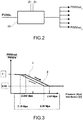
figure 2 is a block diagram representing a control unit of the system offigure 1 ; -
figure 3 is a graph representing an adjustment curve of the system according to the invention; -
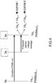
figure 4 is a time graph illustrating a procedure for controlling the rotation speed of the fan; -
figures 5a and5b are graphs representing the time variation of some state quantities, respectively in a system without control according to the invention and in a system provided with such control. - With reference to
figure 1 , an air conditioning system for a vehicle comprises aduct 10 to supply treated air to a vehicle passenger compartment, shown schematically in the figure. Along the duct 10 afan 11 is arranged, configured to generate in the duct 10 a flow of air F to be fed into the vehicle compartment. The fan 11 (or more precisely the impeller thereof) is driven in rotation by anelectric motor 12. - Along the
duct 10 is further arranged anevaporator 13 configured for a heat exchange between a coolant and the air flow F passing through theevaporator 13. Theevaporator 13 is part of a coolant circuit conventional per se (partially illustrated), typically comprising a compressor C1, a condenser C2 and an expansion valve. Infigure 1 , an inlet is shown at I through which the coolant coming from the coolant circuit is fed into theevaporator 13, while at O is represented an outlet through which the coolant returning to the fluid circuit exits from theevaporator 13. - The system further comprises at least one
pressure sensor 15 configured to measure the pressure of the coolant in the relevant circuit. In particular,such sensor 15 is positioned at the outlet of the compressor C1, i.e. at the highest pressure point of the coolant circuit. - The system further comprises a
control unit 20 configured to adjust the rotation speed of thefan 11, controlling themotor 12. - With reference also to
figure 2 , acontrol unit 20 in charge of controlling several distinct groups numbered from 1 to K is represented, each group comprising an evaporator with a fan attached thereto. Thecontrol unit 20 is configured to receive a control signal PWMin as input indicating a fan rotation speed request, which may derive from a manual adjustment carried out by the driver or by a calculation made by thesame control unit 20 on the basis of an air conditioning system control algorithm. For example, the control signal PWMin may have a value between 0 and 100%, where 0 represents the fan at a standstill and 100% represents the fan running at the maximum permitted speed. - The
control unit 20 is further configured to receive as input measurement signals p1,..., pK provided by the pressure sensors respectively associated with each of the coolant circuits K of the system. - With reference also to
figure 3 , thecontrol unit 20 is configured to automatically decrease the rotation speed of the fan 11 (or, in the case of more than one group, the rotation speed of at least one of the fans respectively associated with the evaporators K) when the pressure p measured by the coolant (or, in the case of more than one group, the pressures p1 ... pK measured by the sensors respectively associated with the coolant circuits K) rises above a pressure threshold. In the example shown, this threshold is set to 2.19 MPa. - The decrease of the rotation speed of the fan generates a lower air flow on the evaporator, which allows the pressure of the coolant circuit to be kept below a predetermined maximum value, depending on the characteristics of the adjustment curve of the system. For example, in the example shown in
figure 3 , the maximum preset pressure value is 2.25 MPa, while the fan rotation speed may be reduced at most to 45% compared to the required input speed PWMin. - Specifically, the control unit is configured to generate a control signal PWMout (or, in the case of more than one group, control signals PWMouti ... PWMoutN), which is transmitted to the
motor 12, in a manner known per se, to adjust the rotation speed of thefan 11. The control signal PWMout has a characteristic (e.g. impulse duration) proportional to the rotation speed of thefan 11. Such characteristic of the control signal PWMout follows a predetermined adjustment curve, in particular a curve with hysteresis, as a function of the pressure p measured by thepressure sensor 15, or a quantity (e.g. voltage) of the electrical signal provided by thesensor 15, proportional to the pressure p. - In the graph in
figure 3 , the adjustment curve is expressed by the ratio between the control signal PWMout output from thecontrol unit 20 and the control signal PWMin received as input by thecontrol unit 20 and indicative of the rotation speed request. - The adjustment curve comprises a first curve, indicated at I, and a second curve II, in which, at the same pressure (or voltage), the characteristic PWMout/PWMin of the control signal of the first curve I has a value greater than the characteristic PWMout/PWMin of the control signal of the second curve II. In the example shown, each curve I and II comprises a section with a constant value of the characteristic PWMout/PWMin, and a section wherein such characteristic varies linearly. The hysteresis cycle is between two end points, at which the curves I and II join each other. In the example shown, the first end point has an abscissa equal to 2.19 MPa and an ordinate equal to 1 (i.e. no speed reduction with respect to the incoming control signal PWMin), and the second end point has an abscissa of 2.44 MPa and an ordinate of 0.55 (i.e. 45% speed reduction with respect to the incoming control signal PWMin). Obviously, the values indicated above are subject to calibration as a function of the specific application for which the system is intended according to the invention.
- With reference also to
figure 4 , thecontrol unit 20 is configured for - calculating the average value of a signal representative of the measured pressure of the coolant in a respective time interval,
- comparing the average value of the signal calculated for a given time interval with the average value of the signal calculated for a prior time interval, and
- if the average value of the signal calculated for the given time interval is greater than the average value of the signal calculated for the prior time interval, generating a control signal according to the first curve, and
- if the average value of the signal calculated for the given time interval is lower than the average value of the signal calculated for the prior time interval, generating a control signal according to the second curve.
- In the example shown in
figure 4 , the average value of the signal representative of the pressure corresponding to the average value of the voltage of the signal supplied by thepressure sensor 15, and is indicated at Vs. The subscripts n and n-1 used infigure 4 indicate that the average value Vsn is calculated over a time interval prior to the n-th instant, while the average value Vsn-1 is calculated over an interval prior to the n-1-th instant, that is the instant 0 of the graph infigure 4 . Similarly, the control signal PWMout emitted by thecontrol unit 20 to adjust the speed is marked by the subscript n when it is output at the n-th instant, and the subscript n-1 when it is output at the n-1-th instant (instant 0). - The system thus applies a constant control signal PWMout over the entire time interval between the n-1-th instant and the n-th instant, which in the example shown is 5 s. The voltage values measured in a fraction of this time interval ending at the n-th instant (in the example shown, the sub-interval between 3 s and 5 s) are supplied to the
control unit 20 for it to calculate the average value Vsn. - The
control unit 20 thus compares such average value Vsn-1 with the average value previously calculated with respect to the time interval of equal length prior to the instant n-1 (instant 0 infigure 4 ). On the basis of such comparison, thecontrol unit 20 then determines whether the value PWMoutn to be supplied at the n-th instant should be taken from the curve I (if Vsn> Vsn-1) or from the curve II (if Vsn< Vsn-1). - The arrangements described above prevent fluctuations in the pressure of the coolant in the circuit.
-
Figures 5a and5b are graphs that represent the time variation of some state quantities in a shutdown test, respectively for a system without pressure control according to the invention and for a system provided with such control. The axis of the abscissa represents time, in arbitrary units, while the ordinate shows temperature and pressure. - From the comparison between the two graphs it may be observed that both systems reach the pressure corresponding to the compressor shutdown point, slightly higher than 2.50 MPa, but with a temperature equal to about 55°C in the system with pressure control, higher than the temperature of about 52°C in the system without such control.
Claims (5)
- An air conditioning system for a vehicle, comprising
an evaporator (13) configured for heat exchange between a coolant and air,
a fan (11) configured to generate an air flow (F) flowing through the evaporator (13) and intended to be fed into a passenger compartment of the vehicle,
at least one pressure sensor (15) configured to measure the pressure of the coolant, and
control means (20) for adjusting the rotation speed of the fan (11), wherein said control means (20) are configured to automatically decrease the rotation speed of the fan (11) when the measured pressure of the coolant rises above a pressure threshold, in such a way as to reduce the air flow on the evaporator (13) and therefore reduce the pressure of the coolant, wherein said control means (20) are further configured to generate a control signal (PWMout) for adjusting the rotation speed of the fan (11), said control signal having a characteristic proportional to the rotation speed of the fan (11), and wherein said characteristic of the control signal follows a predetermined adjustment curve as a function of the measured pressure of the coolant,
the air conditioning system characterised in that said adjustment curve comprises a first curve (I) and a second curve (II) in which, for the same pressure, the characteristic of the control signal of the first curve (I) has a greater value than the characteristic of the control signal of the second curve (II), and wherein said control means are configured to
calculate the average value (VSn) of a signal representative of the measured pressure of the coolant in a respective time interval,
compare the average value (VSn) of the signal calculated for a given time interval with the average value of the signal (VSn-1) calculated for a prior time interval, and
if the average value of the signal (VSn) calculated for the given time interval is greater than the average value of the signal (VSn-1) calculated for the prior time interval, generate a control signal according to the first curve (I), and
if the average value of the signal (VSn) calculated for the given time interval is less than the average value of the signal (VSn-1) calculated for the prior time interval, generate a control signal according to the second curve (II). - A system according to claim 1, wherein the pressure sensor (15) is positioned at the output of a compressor (C1) of a circuit of the coolant.
- A method for adjusting the pressure of the coolant of an air conditioning system of a vehicle, comprising
measuring the pressure of the coolant, and
adjusting the rotation speed of a fan (11) generating an air flow (F) flowing through the evaporator (13) of a circuit of the coolant,
wherein adjusting the rotation speed of the fan (11) comprises
automatically decreasing the rotation speed of the fan (11) when the measured pressure of the coolant rises above a pressure threshold, in such a way as to reduce the air flow on the evaporator (13) and therefore reduce the pressure of the coolant, wherein adjusting the rotation speed of the fan (11) further comprises
generating a control signal (PWMout) to adjust the rotation speed of the fan (11), said control signal having a characteristic proportional to the rotation speed of the fan (11), and wherein said characteristic of the control signal follows a predetermined adjustment curve as a function of the measured pressure of the coolant,
the method characterised in that said adjustment curve comprises a first curve (I) and a second curve (II) in which, for the same pressure, the characteristic of the control signal of the first curve (I) has a greater value than the characteristic of the control signal of the second curve (II), and wherein adjusting the rotation speed of the fan (11) comprises
calculating the average value (Vsn) of a signal representative of the measured pressure of the coolant in a respective time interval,
comparing the average value (Vsn) of the signal calculated for a given time interval with the average value of the signal (VSn-1) calculated for a prior time interval, and
if the average value of the signal (Vsn) calculated for the given time interval is greater than the average value of the signal (VSn-1) calculated for the prior time interval, generating a control signal according to the first curve (I), and
if the average value of the signal (Vsn) calculated for the given time interval is lower than the average value of the signal (VSn-1) calculated for the prior time interval, generating a control signal according to the second curve (II). - A computer program comprising instructions to cause the system of claim 1 to execute the steps of the method of claim 3.
- A readable computer medium having stored thereon the computer program of claim 4.
Priority Applications (1)
| Application Number | Priority Date | Filing Date | Title |
|---|---|---|---|
| PL18210916T PL3499143T3 (en) | 2017-12-13 | 2018-12-07 | Air conditioning system with coolant pressure management |
Applications Claiming Priority (1)
| Application Number | Priority Date | Filing Date | Title |
|---|---|---|---|
| IT201700143510 | 2017-12-13 |
Publications (2)
| Publication Number | Publication Date |
|---|---|
| EP3499143A1 EP3499143A1 (en) | 2019-06-19 |
| EP3499143B1 true EP3499143B1 (en) | 2020-09-09 |
Family
ID=61656250
Family Applications (1)
| Application Number | Title | Priority Date | Filing Date |
|---|---|---|---|
| EP18210916.5A Active EP3499143B1 (en) | 2017-12-13 | 2018-12-07 | Air conditioning system with coolant pressure management |
Country Status (4)
| Country | Link |
|---|---|
| US (1) | US11491848B2 (en) |
| EP (1) | EP3499143B1 (en) |
| ES (1) | ES2834447T3 (en) |
| PL (1) | PL3499143T3 (en) |
Family Cites Families (5)
| Publication number | Priority date | Publication date | Assignee | Title |
|---|---|---|---|---|
| JP3010888B2 (en) * | 1992-03-23 | 2000-02-21 | 株式会社デンソー | Vehicle cooling fan speed controller |
| JPH09243185A (en) * | 1996-03-07 | 1997-09-16 | Matsushita Electric Ind Co Ltd | Refrigeration cycle operating method and refrigeration system using the same |
| US5782101A (en) * | 1997-02-27 | 1998-07-21 | Carrier Corporation | Heat pump operating in the heating mode refrigerant pressure control |
| JP6079852B1 (en) * | 2015-10-30 | 2017-02-15 | ダイキン工業株式会社 | Air conditioner |
| GB201520362D0 (en) * | 2015-11-19 | 2016-01-06 | G A H Refrigeration Ltd | Refrigeration system and method |
-
2018
- 2018-12-07 ES ES18210916T patent/ES2834447T3/en active Active
- 2018-12-07 EP EP18210916.5A patent/EP3499143B1/en active Active
- 2018-12-07 PL PL18210916T patent/PL3499143T3/en unknown
- 2018-12-13 US US16/219,821 patent/US11491848B2/en active Active
Non-Patent Citations (1)
| Title |
|---|
| None * |
Also Published As
| Publication number | Publication date |
|---|---|
| US20190176576A1 (en) | 2019-06-13 |
| ES2834447T3 (en) | 2021-06-17 |
| EP3499143A1 (en) | 2019-06-19 |
| US11491848B2 (en) | 2022-11-08 |
| PL3499143T3 (en) | 2021-04-06 |
Similar Documents
| Publication | Publication Date | Title |
|---|---|---|
| US7735744B2 (en) | Control of coolant flow rate for vehicle heating | |
| JP5055122B2 (en) | System and method for controlling cooling fan based on vehicle speed and pressure of air conditioning system | |
| US8745997B2 (en) | Optimized cooling for vehicle with start-stop technology | |
| CN112455212B (en) | Cooling control method and system for vehicle electric driving cooling loop | |
| US7793746B2 (en) | Noise-comfort function for cooling systems with proportional variable speed fans | |
| US11011961B2 (en) | System for cooling an electric machine | |
| US8682527B2 (en) | Cooling system compressor with variable operating range | |
| US10625568B2 (en) | Energy consumption of a multiple zone heating, ventilating and air conditioning system for a vehicle and method | |
| US20070000266A1 (en) | Method and system for controlling a compressor for an HVAC module | |
| US20110271698A1 (en) | Method Of Controlling A Compressor In An Air-Conditioning System | |
| US20070000265A1 (en) | Method and system for cooling a work machine compartment | |
| US20160114653A1 (en) | System and Method for Controlling a Heating and Air Conditioning System in a Vehicle | |
| US20130094972A1 (en) | Climate Thermal Load Based Minimum Flow Rate Water Pump Control | |
| US6337949B1 (en) | System for controlling an electric motor of a fan associated with heat exchangers in a motor vehicle | |
| US11491848B2 (en) | Air conditioning system with coolant pressure management | |
| KR101946951B1 (en) | System and method for controlling an air conditioning system for a motor vehicle | |
| US20240399929A1 (en) | Adaptive high voltage battery cooling | |
| US10981434B2 (en) | Vehicle air-conditioning system and method of operation | |
| EP2934927B1 (en) | Method of torque prediction for automotive air conditioning compressor | |
| US20170191402A1 (en) | Engine cooling dual fan system with ec and dc motors and method of operating | |
| JP2001138736A (en) | Engine control device for hybrid vehicle | |
| CN118514478B (en) | Method of ECU controller controlling ball valve thermostat | |
| WO2013022432A1 (en) | Motor vehicle refrigeration control system | |
| GB2419663A (en) | Temperature control system for motor vehicle passenger compartments | |
| CN121947084A (en) | Full-automatic temperature control system and control method thereof |
Legal Events
| Date | Code | Title | Description |
|---|---|---|---|
| PUAI | Public reference made under article 153(3) epc to a published international application that has entered the european phase |
Free format text: ORIGINAL CODE: 0009012 |
|
| STAA | Information on the status of an ep patent application or granted ep patent |
Free format text: STATUS: THE APPLICATION HAS BEEN PUBLISHED |
|
| AK | Designated contracting states |
Kind code of ref document: A1 Designated state(s): AL AT BE BG CH CY CZ DE DK EE ES FI FR GB GR HR HU IE IS IT LI LT LU LV MC MK MT NL NO PL PT RO RS SE SI SK SM TR |
|
| AX | Request for extension of the european patent |
Extension state: BA ME |
|
| STAA | Information on the status of an ep patent application or granted ep patent |
Free format text: STATUS: REQUEST FOR EXAMINATION WAS MADE |
|
| 17P | Request for examination filed |
Effective date: 20191205 |
|
| RBV | Designated contracting states (corrected) |
Designated state(s): AL AT BE BG CH CY CZ DE DK EE ES FI FR GB GR HR HU IE IS IT LI LT LU LV MC MK MT NL NO PL PT RO RS SE SI SK SM TR |
|
| GRAP | Despatch of communication of intention to grant a patent |
Free format text: ORIGINAL CODE: EPIDOSNIGR1 |
|
| STAA | Information on the status of an ep patent application or granted ep patent |
Free format text: STATUS: GRANT OF PATENT IS INTENDED |
|
| INTG | Intention to grant announced |
Effective date: 20200403 |
|
| INTG | Intention to grant announced |
Effective date: 20200403 |
|
| GRAS | Grant fee paid |
Free format text: ORIGINAL CODE: EPIDOSNIGR3 |
|
| GRAA | (expected) grant |
Free format text: ORIGINAL CODE: 0009210 |
|
| STAA | Information on the status of an ep patent application or granted ep patent |
Free format text: STATUS: THE PATENT HAS BEEN GRANTED |
|
| AK | Designated contracting states |
Kind code of ref document: B1 Designated state(s): AL AT BE BG CH CY CZ DE DK EE ES FI FR GB GR HR HU IE IS IT LI LT LU LV MC MK MT NL NO PL PT RO RS SE SI SK SM TR |
|
| REG | Reference to a national code |
Ref country code: GB Ref legal event code: FG4D |
|
| REG | Reference to a national code |
Ref country code: AT Ref legal event code: REF Ref document number: 1312058 Country of ref document: AT Kind code of ref document: T Effective date: 20200915 Ref country code: CH Ref legal event code: EP |
|
| REG | Reference to a national code |
Ref country code: IE Ref legal event code: FG4D |
|
| REG | Reference to a national code |
Ref country code: DE Ref legal event code: R096 Ref document number: 602018007647 Country of ref document: DE |
|
| REG | Reference to a national code |
Ref country code: SE Ref legal event code: TRGR |
|
| REG | Reference to a national code |
Ref country code: NL Ref legal event code: FP |
|
| REG | Reference to a national code |
Ref country code: LT Ref legal event code: MG4D |
|
| PG25 | Lapsed in a contracting state [announced via postgrant information from national office to epo] |
Ref country code: HR Free format text: LAPSE BECAUSE OF FAILURE TO SUBMIT A TRANSLATION OF THE DESCRIPTION OR TO PAY THE FEE WITHIN THE PRESCRIBED TIME-LIMIT Effective date: 20200909 Ref country code: LT Free format text: LAPSE BECAUSE OF FAILURE TO SUBMIT A TRANSLATION OF THE DESCRIPTION OR TO PAY THE FEE WITHIN THE PRESCRIBED TIME-LIMIT Effective date: 20200909 Ref country code: BG Free format text: LAPSE BECAUSE OF FAILURE TO SUBMIT A TRANSLATION OF THE DESCRIPTION OR TO PAY THE FEE WITHIN THE PRESCRIBED TIME-LIMIT Effective date: 20201209 Ref country code: NO Free format text: LAPSE BECAUSE OF FAILURE TO SUBMIT A TRANSLATION OF THE DESCRIPTION OR TO PAY THE FEE WITHIN THE PRESCRIBED TIME-LIMIT Effective date: 20201209 Ref country code: GR Free format text: LAPSE BECAUSE OF FAILURE TO SUBMIT A TRANSLATION OF THE DESCRIPTION OR TO PAY THE FEE WITHIN THE PRESCRIBED TIME-LIMIT Effective date: 20201210 Ref country code: FI Free format text: LAPSE BECAUSE OF FAILURE TO SUBMIT A TRANSLATION OF THE DESCRIPTION OR TO PAY THE FEE WITHIN THE PRESCRIBED TIME-LIMIT Effective date: 20200909 |
|
| REG | Reference to a national code |
Ref country code: AT Ref legal event code: MK05 Ref document number: 1312058 Country of ref document: AT Kind code of ref document: T Effective date: 20200909 |
|
| PG25 | Lapsed in a contracting state [announced via postgrant information from national office to epo] |
Ref country code: RS Free format text: LAPSE BECAUSE OF FAILURE TO SUBMIT A TRANSLATION OF THE DESCRIPTION OR TO PAY THE FEE WITHIN THE PRESCRIBED TIME-LIMIT Effective date: 20200909 Ref country code: LV Free format text: LAPSE BECAUSE OF FAILURE TO SUBMIT A TRANSLATION OF THE DESCRIPTION OR TO PAY THE FEE WITHIN THE PRESCRIBED TIME-LIMIT Effective date: 20200909 |
|
| PG25 | Lapsed in a contracting state [announced via postgrant information from national office to epo] |
Ref country code: SM Free format text: LAPSE BECAUSE OF FAILURE TO SUBMIT A TRANSLATION OF THE DESCRIPTION OR TO PAY THE FEE WITHIN THE PRESCRIBED TIME-LIMIT Effective date: 20200909 Ref country code: EE Free format text: LAPSE BECAUSE OF FAILURE TO SUBMIT A TRANSLATION OF THE DESCRIPTION OR TO PAY THE FEE WITHIN THE PRESCRIBED TIME-LIMIT Effective date: 20200909 Ref country code: CZ Free format text: LAPSE BECAUSE OF FAILURE TO SUBMIT A TRANSLATION OF THE DESCRIPTION OR TO PAY THE FEE WITHIN THE PRESCRIBED TIME-LIMIT Effective date: 20200909 Ref country code: PT Free format text: LAPSE BECAUSE OF FAILURE TO SUBMIT A TRANSLATION OF THE DESCRIPTION OR TO PAY THE FEE WITHIN THE PRESCRIBED TIME-LIMIT Effective date: 20210111 Ref country code: RO Free format text: LAPSE BECAUSE OF FAILURE TO SUBMIT A TRANSLATION OF THE DESCRIPTION OR TO PAY THE FEE WITHIN THE PRESCRIBED TIME-LIMIT Effective date: 20200909 |
|
| PG25 | Lapsed in a contracting state [announced via postgrant information from national office to epo] |
Ref country code: AT Free format text: LAPSE BECAUSE OF FAILURE TO SUBMIT A TRANSLATION OF THE DESCRIPTION OR TO PAY THE FEE WITHIN THE PRESCRIBED TIME-LIMIT Effective date: 20200909 Ref country code: AL Free format text: LAPSE BECAUSE OF FAILURE TO SUBMIT A TRANSLATION OF THE DESCRIPTION OR TO PAY THE FEE WITHIN THE PRESCRIBED TIME-LIMIT Effective date: 20200909 Ref country code: IS Free format text: LAPSE BECAUSE OF FAILURE TO SUBMIT A TRANSLATION OF THE DESCRIPTION OR TO PAY THE FEE WITHIN THE PRESCRIBED TIME-LIMIT Effective date: 20210109 |
|
| REG | Reference to a national code |
Ref country code: DE Ref legal event code: R097 Ref document number: 602018007647 Country of ref document: DE |
|
| REG | Reference to a national code |
Ref country code: ES Ref legal event code: FG2A Ref document number: 2834447 Country of ref document: ES Kind code of ref document: T3 Effective date: 20210617 |
|
| PG25 | Lapsed in a contracting state [announced via postgrant information from national office to epo] |
Ref country code: SK Free format text: LAPSE BECAUSE OF FAILURE TO SUBMIT A TRANSLATION OF THE DESCRIPTION OR TO PAY THE FEE WITHIN THE PRESCRIBED TIME-LIMIT Effective date: 20200909 |
|
| PLBE | No opposition filed within time limit |
Free format text: ORIGINAL CODE: 0009261 |
|
| STAA | Information on the status of an ep patent application or granted ep patent |
Free format text: STATUS: NO OPPOSITION FILED WITHIN TIME LIMIT |
|
| 26N | No opposition filed |
Effective date: 20210610 |
|
| PG25 | Lapsed in a contracting state [announced via postgrant information from national office to epo] |
Ref country code: MC Free format text: LAPSE BECAUSE OF FAILURE TO SUBMIT A TRANSLATION OF THE DESCRIPTION OR TO PAY THE FEE WITHIN THE PRESCRIBED TIME-LIMIT Effective date: 20200909 Ref country code: DK Free format text: LAPSE BECAUSE OF FAILURE TO SUBMIT A TRANSLATION OF THE DESCRIPTION OR TO PAY THE FEE WITHIN THE PRESCRIBED TIME-LIMIT Effective date: 20200909 Ref country code: SI Free format text: LAPSE BECAUSE OF FAILURE TO SUBMIT A TRANSLATION OF THE DESCRIPTION OR TO PAY THE FEE WITHIN THE PRESCRIBED TIME-LIMIT Effective date: 20200909 |
|
| REG | Reference to a national code |
Ref country code: BE Ref legal event code: MM Effective date: 20201231 |
|
| PG25 | Lapsed in a contracting state [announced via postgrant information from national office to epo] |
Ref country code: IE Free format text: LAPSE BECAUSE OF NON-PAYMENT OF DUE FEES Effective date: 20201207 Ref country code: LU Free format text: LAPSE BECAUSE OF NON-PAYMENT OF DUE FEES Effective date: 20201207 Ref country code: IT Free format text: LAPSE BECAUSE OF FAILURE TO SUBMIT A TRANSLATION OF THE DESCRIPTION OR TO PAY THE FEE WITHIN THE PRESCRIBED TIME-LIMIT Effective date: 20200909 |
|
| PG25 | Lapsed in a contracting state [announced via postgrant information from national office to epo] |
Ref country code: MT Free format text: LAPSE BECAUSE OF FAILURE TO SUBMIT A TRANSLATION OF THE DESCRIPTION OR TO PAY THE FEE WITHIN THE PRESCRIBED TIME-LIMIT Effective date: 20200909 Ref country code: CY Free format text: LAPSE BECAUSE OF FAILURE TO SUBMIT A TRANSLATION OF THE DESCRIPTION OR TO PAY THE FEE WITHIN THE PRESCRIBED TIME-LIMIT Effective date: 20200909 |
|
| PG25 | Lapsed in a contracting state [announced via postgrant information from national office to epo] |
Ref country code: MK Free format text: LAPSE BECAUSE OF FAILURE TO SUBMIT A TRANSLATION OF THE DESCRIPTION OR TO PAY THE FEE WITHIN THE PRESCRIBED TIME-LIMIT Effective date: 20200909 |
|
| PG25 | Lapsed in a contracting state [announced via postgrant information from national office to epo] |
Ref country code: BE Free format text: LAPSE BECAUSE OF NON-PAYMENT OF DUE FEES Effective date: 20201231 |
|
| REG | Reference to a national code |
Ref country code: CH Ref legal event code: PL |
|
| PG25 | Lapsed in a contracting state [announced via postgrant information from national office to epo] |
Ref country code: LI Free format text: LAPSE BECAUSE OF NON-PAYMENT OF DUE FEES Effective date: 20211231 Ref country code: CH Free format text: LAPSE BECAUSE OF NON-PAYMENT OF DUE FEES Effective date: 20211231 |
|
| PGFP | Annual fee paid to national office [announced via postgrant information from national office to epo] |
Ref country code: NL Payment date: 20241224 Year of fee payment: 7 Ref country code: PL Payment date: 20241128 Year of fee payment: 7 |
|
| PGFP | Annual fee paid to national office [announced via postgrant information from national office to epo] |
Ref country code: GB Payment date: 20241226 Year of fee payment: 7 |
|
| PGFP | Annual fee paid to national office [announced via postgrant information from national office to epo] |
Ref country code: FR Payment date: 20241127 Year of fee payment: 7 |
|
| PGFP | Annual fee paid to national office [announced via postgrant information from national office to epo] |
Ref country code: SE Payment date: 20241218 Year of fee payment: 7 |
|
| PGFP | Annual fee paid to national office [announced via postgrant information from national office to epo] |
Ref country code: TR Payment date: 20241202 Year of fee payment: 7 |
|
| PGFP | Annual fee paid to national office [announced via postgrant information from national office to epo] |
Ref country code: DE Payment date: 20241227 Year of fee payment: 7 |
|
| PGFP | Annual fee paid to national office [announced via postgrant information from national office to epo] |
Ref country code: ES Payment date: 20250102 Year of fee payment: 7 |