EP3499113A1 - Light guide device for automotive lighting - Google Patents
Light guide device for automotive lighting Download PDFInfo
- Publication number
- EP3499113A1 EP3499113A1 EP18210880.3A EP18210880A EP3499113A1 EP 3499113 A1 EP3499113 A1 EP 3499113A1 EP 18210880 A EP18210880 A EP 18210880A EP 3499113 A1 EP3499113 A1 EP 3499113A1
- Authority
- EP
- European Patent Office
- Prior art keywords
- light guide
- light
- aspherical
- rays
- aspheric
- Prior art date
- Legal status (The legal status is an assumption and is not a legal conclusion. Google has not performed a legal analysis and makes no representation as to the accuracy of the status listed.)
- Granted
Links
Images

Classifications
-
- F—MECHANICAL ENGINEERING; LIGHTING; HEATING; WEAPONS; BLASTING
- F21—LIGHTING
- F21S—NON-PORTABLE LIGHTING DEVICES; SYSTEMS THEREOF; VEHICLE LIGHTING DEVICES SPECIALLY ADAPTED FOR VEHICLE EXTERIORS
- F21S41/00—Illuminating devices specially adapted for vehicle exteriors, e.g. headlamps
- F21S41/10—Illuminating devices specially adapted for vehicle exteriors, e.g. headlamps characterised by the light source
- F21S41/14—Illuminating devices specially adapted for vehicle exteriors, e.g. headlamps characterised by the light source characterised by the type of light source
- F21S41/141—Light emitting diodes [LED]
- F21S41/147—Light emitting diodes [LED] the main emission direction of the LED being angled to the optical axis of the illuminating device
- F21S41/148—Light emitting diodes [LED] the main emission direction of the LED being angled to the optical axis of the illuminating device the main emission direction of the LED being perpendicular to the optical axis
-
- F—MECHANICAL ENGINEERING; LIGHTING; HEATING; WEAPONS; BLASTING
- F21—LIGHTING
- F21S—NON-PORTABLE LIGHTING DEVICES; SYSTEMS THEREOF; VEHICLE LIGHTING DEVICES SPECIALLY ADAPTED FOR VEHICLE EXTERIORS
- F21S41/00—Illuminating devices specially adapted for vehicle exteriors, e.g. headlamps
- F21S41/10—Illuminating devices specially adapted for vehicle exteriors, e.g. headlamps characterised by the light source
- F21S41/14—Illuminating devices specially adapted for vehicle exteriors, e.g. headlamps characterised by the light source characterised by the type of light source
- F21S41/141—Light emitting diodes [LED]
-
- F—MECHANICAL ENGINEERING; LIGHTING; HEATING; WEAPONS; BLASTING
- F21—LIGHTING
- F21S—NON-PORTABLE LIGHTING DEVICES; SYSTEMS THEREOF; VEHICLE LIGHTING DEVICES SPECIALLY ADAPTED FOR VEHICLE EXTERIORS
- F21S41/00—Illuminating devices specially adapted for vehicle exteriors, e.g. headlamps
- F21S41/20—Illuminating devices specially adapted for vehicle exteriors, e.g. headlamps characterised by refractors, transparent cover plates, light guides or filters
- F21S41/24—Light guides
-
- F—MECHANICAL ENGINEERING; LIGHTING; HEATING; WEAPONS; BLASTING
- F21—LIGHTING
- F21S—NON-PORTABLE LIGHTING DEVICES; SYSTEMS THEREOF; VEHICLE LIGHTING DEVICES SPECIALLY ADAPTED FOR VEHICLE EXTERIORS
- F21S41/00—Illuminating devices specially adapted for vehicle exteriors, e.g. headlamps
- F21S41/20—Illuminating devices specially adapted for vehicle exteriors, e.g. headlamps characterised by refractors, transparent cover plates, light guides or filters
- F21S41/25—Projection lenses
-
- F—MECHANICAL ENGINEERING; LIGHTING; HEATING; WEAPONS; BLASTING
- F21—LIGHTING
- F21S—NON-PORTABLE LIGHTING DEVICES; SYSTEMS THEREOF; VEHICLE LIGHTING DEVICES SPECIALLY ADAPTED FOR VEHICLE EXTERIORS
- F21S41/00—Illuminating devices specially adapted for vehicle exteriors, e.g. headlamps
- F21S41/20—Illuminating devices specially adapted for vehicle exteriors, e.g. headlamps characterised by refractors, transparent cover plates, light guides or filters
- F21S41/285—Refractors, transparent cover plates, light guides or filters not provided in groups F21S41/24 - F21S41/2805
-
- F—MECHANICAL ENGINEERING; LIGHTING; HEATING; WEAPONS; BLASTING
- F21—LIGHTING
- F21S—NON-PORTABLE LIGHTING DEVICES; SYSTEMS THEREOF; VEHICLE LIGHTING DEVICES SPECIALLY ADAPTED FOR VEHICLE EXTERIORS
- F21S41/00—Illuminating devices specially adapted for vehicle exteriors, e.g. headlamps
- F21S41/30—Illuminating devices specially adapted for vehicle exteriors, e.g. headlamps characterised by reflectors
- F21S41/32—Optical layout thereof
-
- F—MECHANICAL ENGINEERING; LIGHTING; HEATING; WEAPONS; BLASTING
- F21—LIGHTING
- F21S—NON-PORTABLE LIGHTING DEVICES; SYSTEMS THEREOF; VEHICLE LIGHTING DEVICES SPECIALLY ADAPTED FOR VEHICLE EXTERIORS
- F21S41/00—Illuminating devices specially adapted for vehicle exteriors, e.g. headlamps
- F21S41/30—Illuminating devices specially adapted for vehicle exteriors, e.g. headlamps characterised by reflectors
- F21S41/32—Optical layout thereof
- F21S41/322—Optical layout thereof the reflector using total internal reflection
-
- F—MECHANICAL ENGINEERING; LIGHTING; HEATING; WEAPONS; BLASTING
- F21—LIGHTING
- F21S—NON-PORTABLE LIGHTING DEVICES; SYSTEMS THEREOF; VEHICLE LIGHTING DEVICES SPECIALLY ADAPTED FOR VEHICLE EXTERIORS
- F21S41/00—Illuminating devices specially adapted for vehicle exteriors, e.g. headlamps
- F21S41/30—Illuminating devices specially adapted for vehicle exteriors, e.g. headlamps characterised by reflectors
- F21S41/32—Optical layout thereof
- F21S41/36—Combinations of two or more separate reflectors
- F21S41/365—Combinations of two or more separate reflectors successively reflecting the light
-
- F—MECHANICAL ENGINEERING; LIGHTING; HEATING; WEAPONS; BLASTING
- F21—LIGHTING
- F21S—NON-PORTABLE LIGHTING DEVICES; SYSTEMS THEREOF; VEHICLE LIGHTING DEVICES SPECIALLY ADAPTED FOR VEHICLE EXTERIORS
- F21S43/00—Signalling devices specially adapted for vehicle exteriors, e.g. brake lamps, direction indicator lights or reversing lights
- F21S43/10—Signalling devices specially adapted for vehicle exteriors, e.g. brake lamps, direction indicator lights or reversing lights characterised by the light source
- F21S43/13—Signalling devices specially adapted for vehicle exteriors, e.g. brake lamps, direction indicator lights or reversing lights characterised by the light source characterised by the type of light source
- F21S43/14—Light emitting diodes [LED]
-
- F—MECHANICAL ENGINEERING; LIGHTING; HEATING; WEAPONS; BLASTING
- F21—LIGHTING
- F21S—NON-PORTABLE LIGHTING DEVICES; SYSTEMS THEREOF; VEHICLE LIGHTING DEVICES SPECIALLY ADAPTED FOR VEHICLE EXTERIORS
- F21S43/00—Signalling devices specially adapted for vehicle exteriors, e.g. brake lamps, direction indicator lights or reversing lights
- F21S43/20—Signalling devices specially adapted for vehicle exteriors, e.g. brake lamps, direction indicator lights or reversing lights characterised by refractors, transparent cover plates, light guides or filters
- F21S43/235—Light guides
- F21S43/236—Light guides characterised by the shape of the light guide
-
- F—MECHANICAL ENGINEERING; LIGHTING; HEATING; WEAPONS; BLASTING
- F21—LIGHTING
- F21S—NON-PORTABLE LIGHTING DEVICES; SYSTEMS THEREOF; VEHICLE LIGHTING DEVICES SPECIALLY ADAPTED FOR VEHICLE EXTERIORS
- F21S43/00—Signalling devices specially adapted for vehicle exteriors, e.g. brake lamps, direction indicator lights or reversing lights
- F21S43/20—Signalling devices specially adapted for vehicle exteriors, e.g. brake lamps, direction indicator lights or reversing lights characterised by refractors, transparent cover plates, light guides or filters
- F21S43/235—Light guides
- F21S43/236—Light guides characterised by the shape of the light guide
- F21S43/239—Light guides characterised by the shape of the light guide plate-shaped
-
- F—MECHANICAL ENGINEERING; LIGHTING; HEATING; WEAPONS; BLASTING
- F21—LIGHTING
- F21S—NON-PORTABLE LIGHTING DEVICES; SYSTEMS THEREOF; VEHICLE LIGHTING DEVICES SPECIALLY ADAPTED FOR VEHICLE EXTERIORS
- F21S43/00—Signalling devices specially adapted for vehicle exteriors, e.g. brake lamps, direction indicator lights or reversing lights
- F21S43/20—Signalling devices specially adapted for vehicle exteriors, e.g. brake lamps, direction indicator lights or reversing lights characterised by refractors, transparent cover plates, light guides or filters
- F21S43/235—Light guides
- F21S43/236—Light guides characterised by the shape of the light guide
- F21S43/241—Light guides characterised by the shape of the light guide of complex shape
-
- F—MECHANICAL ENGINEERING; LIGHTING; HEATING; WEAPONS; BLASTING
- F21—LIGHTING
- F21S—NON-PORTABLE LIGHTING DEVICES; SYSTEMS THEREOF; VEHICLE LIGHTING DEVICES SPECIALLY ADAPTED FOR VEHICLE EXTERIORS
- F21S43/00—Signalling devices specially adapted for vehicle exteriors, e.g. brake lamps, direction indicator lights or reversing lights
- F21S43/20—Signalling devices specially adapted for vehicle exteriors, e.g. brake lamps, direction indicator lights or reversing lights characterised by refractors, transparent cover plates, light guides or filters
- F21S43/235—Light guides
- F21S43/242—Light guides characterised by the emission area
- F21S43/243—Light guides characterised by the emission area emitting light from one or more of its extremities
-
- F—MECHANICAL ENGINEERING; LIGHTING; HEATING; WEAPONS; BLASTING
- F21—LIGHTING
- F21S—NON-PORTABLE LIGHTING DEVICES; SYSTEMS THEREOF; VEHICLE LIGHTING DEVICES SPECIALLY ADAPTED FOR VEHICLE EXTERIORS
- F21S43/00—Signalling devices specially adapted for vehicle exteriors, e.g. brake lamps, direction indicator lights or reversing lights
- F21S43/20—Signalling devices specially adapted for vehicle exteriors, e.g. brake lamps, direction indicator lights or reversing lights characterised by refractors, transparent cover plates, light guides or filters
- F21S43/235—Light guides
- F21S43/247—Light guides with a single light source being coupled into the light guide
-
- F—MECHANICAL ENGINEERING; LIGHTING; HEATING; WEAPONS; BLASTING
- F21—LIGHTING
- F21S—NON-PORTABLE LIGHTING DEVICES; SYSTEMS THEREOF; VEHICLE LIGHTING DEVICES SPECIALLY ADAPTED FOR VEHICLE EXTERIORS
- F21S43/00—Signalling devices specially adapted for vehicle exteriors, e.g. brake lamps, direction indicator lights or reversing lights
- F21S43/20—Signalling devices specially adapted for vehicle exteriors, e.g. brake lamps, direction indicator lights or reversing lights characterised by refractors, transparent cover plates, light guides or filters
- F21S43/26—Refractors, transparent cover plates, light guides or filters not provided in groups F21S43/235 - F21S43/255
-
- G—PHYSICS
- G02—OPTICS
- G02B—OPTICAL ELEMENTS, SYSTEMS OR APPARATUS
- G02B27/00—Optical systems or apparatus not provided for by any of the groups G02B1/00 - G02B26/00, G02B30/00
- G02B27/30—Collimators
-
- F—MECHANICAL ENGINEERING; LIGHTING; HEATING; WEAPONS; BLASTING
- F21—LIGHTING
- F21W—INDEXING SCHEME ASSOCIATED WITH SUBCLASSES F21K, F21L, F21S and F21V, RELATING TO USES OR APPLICATIONS OF LIGHTING DEVICES OR SYSTEMS
- F21W2107/00—Use or application of lighting devices on or in particular types of vehicles
- F21W2107/10—Use or application of lighting devices on or in particular types of vehicles for land vehicles
-
- F—MECHANICAL ENGINEERING; LIGHTING; HEATING; WEAPONS; BLASTING
- F21—LIGHTING
- F21Y—INDEXING SCHEME ASSOCIATED WITH SUBCLASSES F21K, F21L, F21S and F21V, RELATING TO THE FORM OR THE KIND OF THE LIGHT SOURCES OR OF THE COLOUR OF THE LIGHT EMITTED
- F21Y2115/00—Light-generating elements of semiconductor light sources
- F21Y2115/10—Light-emitting diodes [LED]
Definitions
- Exterior vehicle lighting devices may perform stop light functions, taillight functions, headlamp functions, daytime running light functions, dynamic bending light functions, and fog light functions.
- a lighting device may include a light guide to guide light from a light source to an exit surface. Due to manufacturing and other design requirements, a flat light guide thickness may be restricted although a larger output spot size is desired. Accordingly, what is needed, as recognized by the present inventors, is a device for automotive lighting and signaling having an adaptable output spot size.
- An aspect of the present disclosure includes a device for automotive lighting.
- the device includes a light source configured to provide light rays and a light guide.
- the light guide includes two or more aspheric surfaces having at least a common focal point. The two or more aspheric surfaces are configured to maintain total internal reflection of the light rays in the light guide.
- concave sides associated with the two or more aspheric surfaces are opposite to each other.
- the aspherical surface is an elliptical surface.
- the aspherical surface is a parabolic surface.
- a height of the light rays at an exit surface of the light guide is a function of a first focal length associated with a first aspherical surface and a second focal length associated with a second aspherical surface.
- the device further comprises a flat surface opposite to the first aspherical surface and a second flat surface opposite to the second aspherical surface, wherein the first flat surface is connected to the second aspherical surface.
- the light guide includes a flat section.
- the device further includes a collimator configured to collimate light rays from the light source.
- the light source is a light emitting diode.
- the device further comprises an outer lens operatively coupled to the light guide.
- An aspect of the present disclosure includes a light guide for automotive lighting.
- the light guide includes two or more aspheric surfaces having at least a common focal point, the two or more aspheric surfaces configured to maintain total internal reflection of light rays propagating in the light guide.
- An aspect of the present disclosure includes a method for controlling output light rays.
- the method includes providing a light guide operably coupled to a light source and providing two or more aspherical surfaces configured to maintain total internal reflection in the light guide.
- the two or more aspherical surfaces have at least one common focal point.
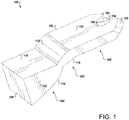
- FIG. 1 is a schematic that shows a device 100 for automotive lighting and/or signalling according to one example.
- the device 100 may include a light guide 102 configured to propagate light rays emitted by a light source 104.
- the light guide 104 may be a structure formed by a glass material or a polymer material (e.g., polycarbonate, polymethyl methacrylate (PMMA)), or any other transparent material having a refractive index greater (e.g., 1.49 for PMMA) than the refractive index of the environment where the light guide 102 is used.
- the light guide 102 may also be made of a colored material (e.g., red, yellow) in accordance with the application for which the device 100 is used.
- the light source 104 may include one or more light emitting devices (LEDs) or solid state light sources.
- the light emitted by the light source may have different shapes and colors based on the intended application.
- the light source 104 may include an inorganic semiconductor light emitting diode or a laser diode, an organic light emitting diode (OLED), a polymer light emitting diode (PLED), a LED lamp package, a LED chip or a LED die, or an array of one or more of these devices. When a plurality of devices of LEDs is used, the LEDs may have the same or different colors.
- the light source 104 may be controlled using a controller (not shown).
- the light source 104 may include fiberoptic device outputs. In one example, the output power of the light source 104 may be based on the application.
- the light guide 102 include an entrance surface 106 by which light rays from the light source 104 enter the light guide 102 and an exit surface 108 by which the rays exit the light guide 102.
- the light guide 102 is used to transmit light from the light source 104 to the exit surface 108.
- the light maintains total internal reflection (TIR).
- TIR total internal reflection
- the light rays are guided along the light guide 102 by successive total reflection on one or more guiding surfaces of the light guide 102 as described further below.
- the light rays entering the light guide 102 are collimated. In other words, the rays are substantially parallel.
- the light guide 102 may include a collimator 110.
- the collimator 110 is configured to collimate rays from the light source 104.
- the collimator 110 may be positioned between the light source 104 and the light guide 102 for creating the collimated rays.
- the collimator 110 is a part of the device 100 and forms a continuous structure with the light guide 102.
- the light guide 102 and the collimator 110 may be molded as one entity.
- the collimator 110 may be separate from the light guide 102.
- the light guide 102 may include two flat surfaces 124 substantially parallel to each other.
- the first section 200 may be of constant height.
- the collimated rays are not subjected to any modification in the first section 200 of the light guide 102.
- the light guide 102 may have a rectangular cross section in the first section 200.
- the light guide 102 includes a first aspheric surface 112.
- the light guide 102 includes a second aspheric surface 114 having at least a common focal point with the first aspheric surface 112.
- the light guide includes a flat surface 116 opposite to the first aspheric surface 112.
- the flat surface 116 connects the flat surface 124 of the first section 200 to the second aspheric surface 112.
- the light guide 102 includes a second flat surface 118 that is opposite to the second aspheric surface 114.
- At least one of the aspherical surfaces 112, 114 may be an elliptical surface. In other implementations, all the aspherical surfaces can be elliptical surfaces.
- At least one of the aspherical surfaces 112, 114 may be a parabolic surface. In other implementations, all the aspherical surfaces can be parabolic surfaces.
- the first aspheric surface 112 and the second aspheric surface 114 function to control an output size of the light rays.
- the first aspheric surface 112 and the second aspheric surface 114 are optimized for a minimum package needed to maintain total internal reflection inside the light guide 102.
- the first aspherical surface 112 and the second aspheric surface 114 may be a parabolic surface, an elliptical surface, or a hyperbolic surface.
- the first aspheric surface 112 and the second aspheric surface 114 face each other. In other words, the concave side of each of the first aspheric surface 112 and the second aspheric surface 114 face each other.
- the at least common focal point is located inside the light guide 102.
- the light rays are incident on and totally reflected of the first aspheric surface 112. Then, the light rays are incident on and totally reflected of the second aspheric surface 114. Parallel rays to the axis of the first aspheric surface (i.e., direction of collimated in the first section) are reflect to the common focal point. The light rays passing by the common focal point of the second aspheric surface 114 are then collimated.
- the first aspheric surface 112 is optimized such as an incident ray have an incident angle with respect to the normal of the first aspheric surface greater than a critical angle of reflection is capable of being totally reflected by the first aspheric surface 112.
- the second aspheric surface 114 is also optimized such as the light rays reflected from the first aspheric surface 112 have an incident angle with respect to the a normal to the second aspheric surface 114 greater than a critical angle of reflection and are capable of being totally reflected by the second aspheric surface 114.
- the light guide 102 may be delimited laterally by a rear edge 120 and side edges 122.
- the light rays may be input via the rear edge 118.
- the side edges 120 are perpendicular to the guiding surfaces (i.e., first aspheric surface 112, second aspheric surface 114, first flat surface 116, second flat surface 118, flat surfaces 124).
- the height of the light guide 102 may vary along a longitudinal direction of the light guide 102.
- the device 100 may be fabricated using injection molding techniques.
- the light guide 102 and the collimator 110 may be made using one piece of material.
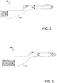
- FIG. 2 is a side view of the device 100 to one example.
- the height of the beam at the exit surface 104 is indicated by “b” in FIG. 2 .
- the height of the beam in the first section 200 of the light guide 102 is indicated by “a”.
- the ratio between "b” and “a” is proportional to the ratio between a first focal length associated with the first aspherical surface 112 and a second focal length associated with the second aspherical surface 114. In FIG. 2 , the ratio between "b” and “a” is 1.
- the height of the beam is not changed by the aspheric surfaces.
- FIG. 3 is a side view of the device 100 according to one example.
- the ratio between "b" and "a" is 2.
- the height of the exiting beam is double the height of the beam in the first section 200 of the light guide 102.
- the focal length associated with each of the aspherical surfaces the height of the beam at the exit surface 108 may be adapted to the application.
- FIG. 4 is a side view of the light guide 102 that shows a light rays path according to one example.
- Point 206 indicates the common focal point for the exemplary aspheric surfaces shown in FIG. 4 .
- an exit surface thickness may vary from 5mm up to 100mm.
- the light guide 102 may include one or more additional sections to reorient the exit direction of the rays.
- An orientation angle may vary based on the application.
- the rays may be reoriented by 90°.
- the device 100 may include optics deposited at the exit surface 108.
- the optics are configured to redirect the light from the device 100.
- a separate outer lens may be used.
- the separate outer lens may include spreading elements to direct the light in a desired direction.
- the outer lens may be made of plastic, glass, or any transparent covers such as a tail light cover.
- the separate lens may also provide aesthetic advantages for the light guide 102.
- a device which includes the features in the foregoing description provides numerous advantages.
- a variable output size may be obtained while adhering to manufacturing requirements.
Landscapes
- Engineering & Computer Science (AREA)
- General Engineering & Computer Science (AREA)
- Physics & Mathematics (AREA)
- Optics & Photonics (AREA)
- Microelectronics & Electronic Packaging (AREA)
- General Physics & Mathematics (AREA)
- Non-Portable Lighting Devices Or Systems Thereof (AREA)
- Planar Illumination Modules (AREA)
Abstract
Description
- Motor vehicles contain numerous lighting devices for both interior and exterior illumination. For example, exterior vehicle lighting devices may perform stop light functions, taillight functions, headlamp functions, daytime running light functions, dynamic bending light functions, and fog light functions.
- A lighting device may include a light guide to guide light from a light source to an exit surface. Due to manufacturing and other design requirements, a flat light guide thickness may be restricted although a larger output spot size is desired. Accordingly, what is needed, as recognized by the present inventors, is a device for automotive lighting and signaling having an adaptable output spot size.
- The foregoing "Background" description is for the purpose of generally presenting the context of the disclosure. Work of the inventors, to the extent it is described in this background section, as well as aspects of the description which may not otherwise qualify as prior art at the time of filing, are neither expressly or impliedly admitted as prior art against the present invention.
- An aspect of the present disclosure includes a device for automotive lighting. The device includes a light source configured to provide light rays and a light guide. The light guide includes two or more aspheric surfaces having at least a common focal point. The two or more aspheric surfaces are configured to maintain total internal reflection of the light rays in the light guide.
- In a further aspect of the present disclosure, concave sides associated with the two or more aspheric surfaces are opposite to each other.
- In a further aspect of the present disclosure, the aspherical surface is an elliptical surface.
- In a further aspect of the present disclosure, the aspherical surface is a parabolic surface.
- In a further aspect of the present disclosure, a height of the light rays at an exit surface of the light guide is a function of a first focal length associated with a first aspherical surface and a second focal length associated with a second aspherical surface.
- In a further aspect of the present disclosure, the device further comprises a flat surface opposite to the first aspherical surface and a second flat surface opposite to the second aspherical surface, wherein the first flat surface is connected to the second aspherical surface.
- In a further aspect of the present disclosure, the light guide includes a flat section.
- In a further aspect of the present disclosure, the device further includes a collimator configured to collimate light rays from the light source.
- In a further aspect of the present disclosure, the light source is a light emitting diode.
- In a further aspect of the present disclosure, the device further comprises an outer lens operatively coupled to the light guide.
- An aspect of the present disclosure includes a light guide for automotive lighting. The light guide includes two or more aspheric surfaces having at least a common focal point, the two or more aspheric surfaces configured to maintain total internal reflection of light rays propagating in the light guide.
- An aspect of the present disclosure includes a method for controlling output light rays. The method includes providing a light guide operably coupled to a light source and providing two or more aspherical surfaces configured to maintain total internal reflection in the light guide. The two or more aspherical surfaces have at least one common focal point.
- The foregoing paragraphs have been provided by way of general introduction, and are not intended to limit the scope of the following claims. The described embodiments, together with further advantages, will be best understood by reference to the following detailed description taken in conjunction with the accompanying drawings.
- A more complete appreciation of the disclosure and many of the attendant advantages thereof will be readily obtained as the same becomes better understood by reference to the following detailed description when considered in connection with the accompanying drawings, wherein:
-
FIG. 1 is a schematic of a device for automotive lighting and/or signaling according to one example; -
FIG. 2 is a side view of the device for automotive lighting and/or signaling according to one example; -
FIG. 3 is a side view of the device for automotive lighting and/or signaling according to another example; and -
FIG. 4 is a side view of the device that shows an optical path of the light according to one example. - Referring now to the drawings, wherein like reference numerals designate identical or corresponding parts throughout several views, the following description relates to a lighting or signaling device for a motor vehicle and associated methodology for controlling an output spot size of light rays.
-
FIG. 1 is a schematic that shows adevice 100 for automotive lighting and/or signalling according to one example. Thedevice 100 may include alight guide 102 configured to propagate light rays emitted by alight source 104. Thelight guide 104 may be a structure formed by a glass material or a polymer material (e.g., polycarbonate, polymethyl methacrylate (PMMA)), or any other transparent material having a refractive index greater (e.g., 1.49 for PMMA) than the refractive index of the environment where thelight guide 102 is used. In one implementation, thelight guide 102 may also be made of a colored material (e.g., red, yellow) in accordance with the application for which thedevice 100 is used. - The
light source 104 may include one or more light emitting devices (LEDs) or solid state light sources. The light emitted by the light source may have different shapes and colors based on the intended application. For example, thelight source 104 may include an inorganic semiconductor light emitting diode or a laser diode, an organic light emitting diode (OLED), a polymer light emitting diode (PLED), a LED lamp package, a LED chip or a LED die, or an array of one or more of these devices. When a plurality of devices of LEDs is used, the LEDs may have the same or different colors. Thelight source 104 may be controlled using a controller (not shown). Thelight source 104 may include fiberoptic device outputs. In one example, the output power of thelight source 104 may be based on the application. - The
light guide 102 include anentrance surface 106 by which light rays from thelight source 104 enter thelight guide 102 and anexit surface 108 by which the rays exit thelight guide 102. Thelight guide 102 is used to transmit light from thelight source 104 to theexit surface 108. The light maintains total internal reflection (TIR). The light rays are guided along thelight guide 102 by successive total reflection on one or more guiding surfaces of thelight guide 102 as described further below. The light rays entering thelight guide 102 are collimated. In other words, the rays are substantially parallel. - In one implementation, the
light guide 102 may include acollimator 110. Thecollimator 110 is configured to collimate rays from thelight source 104. - In one implementation, the
collimator 110 may be positioned between thelight source 104 and thelight guide 102 for creating the collimated rays. In one example, thecollimator 110 is a part of thedevice 100 and forms a continuous structure with thelight guide 102. In other words, thelight guide 102 and thecollimator 110 may be molded as one entity. In other examples, thecollimator 110 may be separate from thelight guide 102. - In a
first section 200 of thelight guide 102, thelight guide 102 may include two flat surfaces 124 substantially parallel to each other. Thefirst section 200 may be of constant height. The collimated rays are not subjected to any modification in thefirst section 200 of thelight guide 102. Thelight guide 102 may have a rectangular cross section in thefirst section 200. - In a
second section 202, thelight guide 102 includes a firstaspheric surface 112. In athird section 204, thelight guide 102 includes a secondaspheric surface 114 having at least a common focal point with the firstaspheric surface 112. In thesecond section 202, the light guide includes aflat surface 116 opposite to the firstaspheric surface 112. Theflat surface 116 connects the flat surface 124 of thefirst section 200 to thesecond aspheric surface 112. In thethird section 204, thelight guide 102 includes a secondflat surface 118 that is opposite to thesecond aspheric surface 114. - In one implementation, at least one of the
aspherical surfaces - In one implementation, at least one of the
aspherical surfaces - The first
aspheric surface 112 and thesecond aspheric surface 114 function to control an output size of the light rays. The firstaspheric surface 112 and thesecond aspheric surface 114 are optimized for a minimum package needed to maintain total internal reflection inside thelight guide 102. The firstaspherical surface 112 and thesecond aspheric surface 114 may be a parabolic surface, an elliptical surface, or a hyperbolic surface. The firstaspheric surface 112 and thesecond aspheric surface 114 face each other. In other words, the concave side of each of the firstaspheric surface 112 and thesecond aspheric surface 114 face each other. In one implementation, the at least common focal point is located inside thelight guide 102. - The light rays are incident on and totally reflected of the first
aspheric surface 112. Then, the light rays are incident on and totally reflected of thesecond aspheric surface 114. Parallel rays to the axis of the first aspheric surface (i.e., direction of collimated in the first section) are reflect to the common focal point. The light rays passing by the common focal point of thesecond aspheric surface 114 are then collimated. Thus, the firstaspheric surface 112 is optimized such as an incident ray have an incident angle with respect to the normal of the first aspheric surface greater than a critical angle of reflection is capable of being totally reflected by the firstaspheric surface 112. Thesecond aspheric surface 114 is also optimized such as the light rays reflected from the firstaspheric surface 112 have an incident angle with respect to the a normal to thesecond aspheric surface 114 greater than a critical angle of reflection and are capable of being totally reflected by thesecond aspheric surface 114. - The
light guide 102 may be delimited laterally by arear edge 120 and side edges 122. In one implementation, the light rays may be input via therear edge 118. In one implementation, the side edges 120 are perpendicular to the guiding surfaces (i.e., firstaspheric surface 112, secondaspheric surface 114, firstflat surface 116, secondflat surface 118, flat surfaces 124). The height of thelight guide 102 may vary along a longitudinal direction of thelight guide 102. - In one implementation, the
device 100 may be fabricated using injection molding techniques. Thelight guide 102 and thecollimator 110 may be made using one piece of material. -
FIG. 2 is a side view of thedevice 100 to one example. The height of the beam at theexit surface 104 is indicated by "b" inFIG. 2 . The height of the beam in thefirst section 200 of thelight guide 102 is indicated by "a". The ratio between "b" and "a" is proportional to the ratio between a first focal length associated with the firstaspherical surface 112 and a second focal length associated with the secondaspherical surface 114. InFIG. 2 , the ratio between "b" and "a" is 1. The height of the beam is not changed by the aspheric surfaces. -
FIG. 3 is a side view of thedevice 100 according to one example. InFIG. 3 , the ratio between "b" and "a" is 2. Thus, the height of the exiting beam is double the height of the beam in thefirst section 200 of thelight guide 102. Thus, by changing the focal length associated with each of the aspherical surfaces, the height of the beam at theexit surface 108 may be adapted to the application. -
FIG. 4 is a side view of thelight guide 102 that shows a light rays path according to one example.Point 206 indicates the common focal point for the exemplary aspheric surfaces shown inFIG. 4 . In one implementation, an exit surface thickness may vary from 5mm up to 100mm. - In one implementation, the
light guide 102 may include one or more additional sections to reorient the exit direction of the rays. An orientation angle may vary based on the application. In one implementation, the rays may be reoriented by 90°. - In one implementation, the
device 100 may include optics deposited at theexit surface 108. The optics are configured to redirect the light from thedevice 100. In one implementation, a separate outer lens may be used. The separate outer lens may include spreading elements to direct the light in a desired direction. For example, the outer lens may be made of plastic, glass, or any transparent covers such as a tail light cover. The separate lens may also provide aesthetic advantages for thelight guide 102. - Obviously, numerous modifications and variations are possible in light of the above teachings. It is therefore to be understood that within the scope of the appended claims, the invention may be practiced otherwise than as specifically described herein.
- A device which includes the features in the foregoing description provides numerous advantages. In particular, a variable output size may be obtained while adhering to manufacturing requirements.
- Thus, the foregoing discussion discloses and describes merely exemplary embodiments of the present invention. As will be understood by those skilled in the art, the present invention may be embodied in other specific forms without departing from the spirit or essential characteristics thereof. Accordingly, the disclosure of the present invention is intended to be illustrative, but not limiting of the scope of the invention, as well as other claims. The disclosure, including any readily discernible variants of the teachings herein, defines, in part, the scope of the foregoing claim terminology such that no inventive subject matter is dedicated to the public.
Claims (19)
- A device for automotive lighting, the device comprising:a light source configured to provide light rays; anda light guide including two or more aspheric surfaces having at least a common focal point, the two or more aspheric surfaces being configured to maintain total internal reflection of the light rays in the light guide.
- The device of claim 1, wherein concave sides associated with the two or more aspheric surfaces are opposite to each other.
- The device of claim 1, wherein at least one of the aspherical surfaces is an elliptical surface.
- The device of claim 1, wherein at least one of the aspherical surfaces is a parabolic surface.
- The device of claim 1, wherein a height of the light rays at an exit surface of the light guide is a function of a first focal length associated with a first aspherical surface and a second focal length associated with a second aspherical surface.
- The device of claim 5, further comprising a first flat surface opposite to the first aspherical surface and a second flat surface opposite to the second aspherical surface, wherein the first flat surface is connected to the second aspherical surface.
- The device of claim 1, wherein the light guide includes a flat section.
- The device of claim 1, further comprising a collimator configured to collimate light rays from the light source.
- The device of claim 1, wherein the light source is a light emitting diode.
- The device of claim 1, further comprising an outer lens operatively coupled to the light guide.
- A light guide for automotive lighting, the light guide comprising:two or more aspheric surfaces having at least a common focal point, the two or more aspheric surfaces configured to maintain total internal reflection of light rays propagating in the light guide.
- The light guide of claim 11, wherein concave sides associated with the two or more aspheric surfaces are opposite to each other.
- The light guide of claim 11, wherein at least one of the aspherical surfaces is an elliptical surface.
- The light guide of claim 11, wherein at least one of the aspherical surfaces is a parabolic surface.
- The light guide of claim 11, wherein the light guide includes two aspheric surfaces.
- The light guide of claim 15, wherein a height of the light rays at an exit surface of the light guide is a function of a first focal length associated with a first aspherical surface and a second focal length associated with a second aspherical surface.
- The light guide of claim 15, further comprising a first flat surface opposite to the first aspherical surface and a second flat surface opposite to the second aspherical surface, wherein the first flat surface is connected to the second aspherical surface.
- The light guide of claim 11, further comprising a flat section.
- A method for controlling output light rays, the method comprising:providing a light guide operably coupled to a light source;providing two or more aspherical surfaces configured to maintain total internal reflection in the light guide; andwherein the two or more aspherical surfaces have at least one common focal point.
Applications Claiming Priority (1)
| Application Number | Priority Date | Filing Date | Title |
|---|---|---|---|
| US15/841,406 US10288248B1 (en) | 2017-12-14 | 2017-12-14 | Device for automotive lighting |
Publications (2)
| Publication Number | Publication Date |
|---|---|
| EP3499113A1 true EP3499113A1 (en) | 2019-06-19 |
| EP3499113B1 EP3499113B1 (en) | 2026-01-21 |
Family
ID=64664866
Family Applications (1)
| Application Number | Title | Priority Date | Filing Date |
|---|---|---|---|
| EP18210880.3A Active EP3499113B1 (en) | 2017-12-14 | 2018-12-06 | Light guide device for automotive lighting |
Country Status (3)
| Country | Link |
|---|---|
| US (1) | US10288248B1 (en) |
| EP (1) | EP3499113B1 (en) |
| CN (1) | CN109973918B (en) |
Cited By (1)
| Publication number | Priority date | Publication date | Assignee | Title |
|---|---|---|---|---|
| WO2023247799A1 (en) * | 2022-06-24 | 2023-12-28 | Valeo Vision | Light guide, optical irradiation assembly, and motor vehicle |
Families Citing this family (18)
| Publication number | Priority date | Publication date | Assignee | Title |
|---|---|---|---|---|
| DE112016000778B4 (en) | 2015-10-07 | 2025-10-09 | Docter Optics Se | Headlight lens for a vehicle headlight |
| WO2018166911A1 (en) * | 2017-03-17 | 2018-09-20 | Lumileds Holding B.V. | Multi-focal collimating lens and headlight assembly for an automotive low beam |
| EP3671016A1 (en) * | 2018-12-21 | 2020-06-24 | ZKW Group GmbH | Lighting device for a motor vehicle headlamp and motor vehicle headlamp |
| KR102757872B1 (en) * | 2019-06-13 | 2025-01-21 | 현대자동차주식회사 | Slim type lamp apparatus for vehicle |
| JP7278920B2 (en) * | 2019-10-08 | 2023-05-22 | スタンレー電気株式会社 | Light guide lens, lens assembly and vehicle lamp |
| KR102688710B1 (en) * | 2019-11-29 | 2024-07-26 | 에스엘 주식회사 | Lamp for vehicle |
| CN212584877U (en) * | 2020-01-02 | 2021-02-23 | 法雷奥照明公司 | Light guide member, lighting device, and vehicle |
| IT202000002350A1 (en) | 2020-02-06 | 2021-08-06 | Marelli Automotive Lighting Italy S P A Con Socio Unico | LIGHTING DEVICE FOR VEHICLES, IN PARTICULAR LED |
| CN112781001B (en) * | 2020-07-13 | 2025-10-03 | 华域视觉科技(上海)有限公司 | Headlight optical element, headlight module and vehicle |
| CN114034017B (en) * | 2021-09-28 | 2023-07-25 | 东风汽车集团股份有限公司 | Light guide structure, car light and car |
| CN217382775U (en) * | 2021-12-30 | 2022-09-06 | 市光法雷奥(佛山)汽车照明系统有限公司 | Collimators, Lighting Devices and Motor Vehicles |
| CN217763280U (en) * | 2022-04-29 | 2022-11-08 | 市光法雷奥(佛山)汽车照明系统有限公司 | Optical element, vehicle lamp and motor vehicle |
| EP4357667A1 (en) * | 2022-10-21 | 2024-04-24 | ZKW Group GmbH | Illumination device for a motor vehicle headlamp for generating a light distribution |
| TWI826309B (en) * | 2023-04-21 | 2023-12-11 | 矜輝實業有限公司 | Structure of car lamp |
| CN116557807B (en) * | 2023-05-30 | 2025-10-03 | 常州星宇车灯股份有限公司 | Evenly illuminate thick-walled structures and headlights |
| CN117419293A (en) * | 2023-11-24 | 2024-01-19 | 常州星宇车灯股份有限公司 | A new type of light guide that can achieve precise light distribution and lamps and vehicles using this light guide |
| EP4621285A1 (en) * | 2024-03-21 | 2025-09-24 | ZKW Group GmbH | Lighting device for a motor vehicle |
| EP4703628A1 (en) * | 2024-08-30 | 2026-03-04 | ZKW Group GmbH | Lighting device for a vehicle |
Citations (9)
| Publication number | Priority date | Publication date | Assignee | Title |
|---|---|---|---|---|
| DE102005054660A1 (en) * | 2004-11-24 | 2006-06-01 | Koito Manufacturing Co., Ltd. | Vehicle lighting device |
| DE102006023163A1 (en) * | 2005-05-17 | 2006-11-30 | Koito Mfg. Co., Ltd. | Lighting device e.g. headlight, for vehicle, has reflecting surface with parabolic cross-sectional shape which has its focal point as one of the focal point of elliptical shaped cross section of another surface |
| DE102006008191A1 (en) * | 2006-02-22 | 2007-08-23 | Hella Kgaa Hueck & Co. | Illuminating unit for use in motor vehicles e.g. signal light, comprises source of light and source of light in main direction of emission, exterior surfaces or light decoupling surfaces of light guiding element are provided |
| DE102010018119A1 (en) * | 2010-04-24 | 2011-10-27 | Hella Kgaa Hueck & Co. | Optical element for lighting device of vehicle, has body, which is formed of transparent material in one-piece and has multiple bounding surfaces |
| FR2966224A1 (en) * | 2010-10-19 | 2012-04-20 | Valeo Vision | Lighting or signaling device for production of luminous flux to e.g. indicate of motor vehicle, has guiding layer that is provided with reflection unit to direct rays of collimated beam toward guiding layer |
| DE102013210856A1 (en) * | 2013-06-11 | 2014-12-11 | Automotive Lighting Reutlingen Gmbh | Luminaire for a motor vehicle |
| EP2857740A1 (en) * | 2013-10-02 | 2015-04-08 | Automotive Lighting Reutlingen GmbH | Motor vehicle lighting device |
| US20150267895A1 (en) * | 2014-03-24 | 2015-09-24 | Stanley Electric Co., Ltd. | Lighting unit |
| DE102015211969A1 (en) * | 2014-07-04 | 2016-01-07 | Sl Corporation | Headlight for vehicle |
Family Cites Families (17)
| Publication number | Priority date | Publication date | Assignee | Title |
|---|---|---|---|---|
| GB915078A (en) | 1958-05-05 | 1963-01-09 | Nat Res Dev | Improvements in and relating to the production of scales for measurement |
| FR2487970A1 (en) | 1980-07-31 | 1982-02-05 | Barbier Benard & Turenne | Auto collimator rotation measuring process - uses afocal optical system having unity magnification placed in optical beam of mirror and auto-collimator |
| US4353617A (en) | 1980-11-18 | 1982-10-12 | Canon Kabushiki Kaisha | Optical system capable of continuously varying the diameter of a beam spot |
| DE68909553T2 (en) | 1988-10-21 | 1994-01-27 | Thomson Csf | Optical collimation system for a helmet view indicator. |
| US6022114A (en) | 1998-05-01 | 2000-02-08 | Nikon Corporation | Anamorphic afocal beam shaping assembly |
| US6623132B2 (en) * | 1999-08-11 | 2003-09-23 | North American Lighting, Inc. | Light coupler hingedly attached to a light guide for automotive lighting |
| US7055995B1 (en) * | 2002-02-05 | 2006-06-06 | Innovative Lighting, Inc. | Apparatus and method of guiding and shaping light from light source |
| EP1789824A4 (en) * | 2004-08-23 | 2009-01-21 | Optical Res Associates | Lighting systems for producing different beam patterns |
| DE102006044019B4 (en) * | 2006-09-15 | 2011-12-29 | Stiftung Alfred-Wegener-Institut für Polar- und Meeresforschung Stiftung des öffentlichen Rechts | reflector spotlight |
| DE102006044641A1 (en) * | 2006-09-19 | 2008-03-27 | Schefenacker Vision Systems Germany Gmbh | Light unit with LED, light guide and secondary lens |
| JP2012028155A (en) * | 2010-07-23 | 2012-02-09 | Stanley Electric Co Ltd | Lamp unit for vehicle |
| DE102012224079B4 (en) * | 2012-12-20 | 2014-08-21 | Automotive Lighting Reutlingen Gmbh | Light guide with a band-shaped light exit surface |
| JP6131724B2 (en) * | 2013-06-11 | 2017-05-24 | スタンレー電気株式会社 | Vehicle lighting |
| FR3023600B1 (en) * | 2014-07-11 | 2021-04-16 | Valeo Vision | LIGHTING MODULE OF A MOTOR VEHICLE |
| CN205014221U (en) * | 2015-08-20 | 2016-02-03 | 捷光照明科技股份有限公司 | Car lights with chiaroscuro |
| FR3051541B1 (en) * | 2016-05-18 | 2020-04-17 | Valeo Vision | LED PROJECTOR WITH CUT-OUT DIOPTRE FOR VEHICLES |
| KR102594702B1 (en) * | 2016-11-03 | 2023-10-26 | 현대모비스 주식회사 | Light guide unit of vehicle |
-
2017
- 2017-12-14 US US15/841,406 patent/US10288248B1/en active Active
-
2018
- 2018-12-06 EP EP18210880.3A patent/EP3499113B1/en active Active
- 2018-12-13 CN CN201811529058.XA patent/CN109973918B/en active Active
Patent Citations (9)
| Publication number | Priority date | Publication date | Assignee | Title |
|---|---|---|---|---|
| DE102005054660A1 (en) * | 2004-11-24 | 2006-06-01 | Koito Manufacturing Co., Ltd. | Vehicle lighting device |
| DE102006023163A1 (en) * | 2005-05-17 | 2006-11-30 | Koito Mfg. Co., Ltd. | Lighting device e.g. headlight, for vehicle, has reflecting surface with parabolic cross-sectional shape which has its focal point as one of the focal point of elliptical shaped cross section of another surface |
| DE102006008191A1 (en) * | 2006-02-22 | 2007-08-23 | Hella Kgaa Hueck & Co. | Illuminating unit for use in motor vehicles e.g. signal light, comprises source of light and source of light in main direction of emission, exterior surfaces or light decoupling surfaces of light guiding element are provided |
| DE102010018119A1 (en) * | 2010-04-24 | 2011-10-27 | Hella Kgaa Hueck & Co. | Optical element for lighting device of vehicle, has body, which is formed of transparent material in one-piece and has multiple bounding surfaces |
| FR2966224A1 (en) * | 2010-10-19 | 2012-04-20 | Valeo Vision | Lighting or signaling device for production of luminous flux to e.g. indicate of motor vehicle, has guiding layer that is provided with reflection unit to direct rays of collimated beam toward guiding layer |
| DE102013210856A1 (en) * | 2013-06-11 | 2014-12-11 | Automotive Lighting Reutlingen Gmbh | Luminaire for a motor vehicle |
| EP2857740A1 (en) * | 2013-10-02 | 2015-04-08 | Automotive Lighting Reutlingen GmbH | Motor vehicle lighting device |
| US20150267895A1 (en) * | 2014-03-24 | 2015-09-24 | Stanley Electric Co., Ltd. | Lighting unit |
| DE102015211969A1 (en) * | 2014-07-04 | 2016-01-07 | Sl Corporation | Headlight for vehicle |
Cited By (1)
| Publication number | Priority date | Publication date | Assignee | Title |
|---|---|---|---|---|
| WO2023247799A1 (en) * | 2022-06-24 | 2023-12-28 | Valeo Vision | Light guide, optical irradiation assembly, and motor vehicle |
Also Published As
| Publication number | Publication date |
|---|---|
| EP3499113B1 (en) | 2026-01-21 |
| US10288248B1 (en) | 2019-05-14 |
| CN109973918A (en) | 2019-07-05 |
| CN109973918B (en) | 2022-01-04 |
Similar Documents
| Publication | Publication Date | Title |
|---|---|---|
| EP3499113B1 (en) | Light guide device for automotive lighting | |
| US10371341B2 (en) | Vehicle lamp | |
| US9574734B2 (en) | Lightguide module | |
| US8591083B2 (en) | Vehicular lamp | |
| US7686497B2 (en) | Variable planar light guide module | |
| EP3456587B1 (en) | Light beam adjusting device, vehicle lamp and motor vehicle | |
| US7639918B2 (en) | Manifold-type lightguide with reduced thickness | |
| US9442241B2 (en) | Optics for illumination devices | |
| EP2990720B1 (en) | Vehicle lighting unit | |
| US9857044B2 (en) | Lighting apparatus and automobile having lighting apparatus mounted therein | |
| US20150192264A1 (en) | Lighting unit for a headlight | |
| WO2015129251A1 (en) | Illumination device and automotive vehicle in which illumination device is mounted | |
| US10767827B2 (en) | LED lighting device | |
| KR20180024230A (en) | multi facet lens with continuous non-spherical curve | |
| KR20070003938A (en) | Light guiding device and light guiding method | |
| ITTO20010461A1 (en) | LIGHTING DEVICE, PARTICULARLY HEADLIGHT FOR MOTOR VEHICLES OR EMERGENCY LIGHT. | |
| CN207350245U (en) | Realize the lens subassembly of dipped beam | |
| KR20150092652A (en) | Lighting device | |
| CN105276482B (en) | Lighting device and automobile with same | |
| US20230008568A1 (en) | Lighting and/or signaling device for a motor vehicle and a light guide therefor | |
| US20190011626A1 (en) | Optical system for lighting equipment, especially for a signal lamp for motor vehicles | |
| EP3361142A1 (en) | Lighting device comprising an active lens and method for producing thereof | |
| US8303140B2 (en) | Lighting device | |
| US10234095B2 (en) | Lens and vehicle headlamp structure | |
| EP3090300B1 (en) | Lighting device and luminaire |
Legal Events
| Date | Code | Title | Description |
|---|---|---|---|
| PUAI | Public reference made under article 153(3) epc to a published international application that has entered the european phase |
Free format text: ORIGINAL CODE: 0009012 |
|
| STAA | Information on the status of an ep patent application or granted ep patent |
Free format text: STATUS: REQUEST FOR EXAMINATION WAS MADE |
|
| 17P | Request for examination filed |
Effective date: 20181206 |
|
| AK | Designated contracting states |
Kind code of ref document: A1 Designated state(s): AL AT BE BG CH CY CZ DE DK EE ES FI FR GB GR HR HU IE IS IT LI LT LU LV MC MK MT NL NO PL PT RO RS SE SI SK SM TR |
|
| AX | Request for extension of the european patent |
Extension state: BA ME |
|
| STAA | Information on the status of an ep patent application or granted ep patent |
Free format text: STATUS: EXAMINATION IS IN PROGRESS |
|
| 17Q | First examination report despatched |
Effective date: 20220125 |
|
| P01 | Opt-out of the competence of the unified patent court (upc) registered |
Effective date: 20230602 |
|
| GRAP | Despatch of communication of intention to grant a patent |
Free format text: ORIGINAL CODE: EPIDOSNIGR1 |
|
| STAA | Information on the status of an ep patent application or granted ep patent |
Free format text: STATUS: GRANT OF PATENT IS INTENDED |
|
| INTG | Intention to grant announced |
Effective date: 20250123 |
|
| GRAJ | Information related to disapproval of communication of intention to grant by the applicant or resumption of examination proceedings by the epo deleted |
Free format text: ORIGINAL CODE: EPIDOSDIGR1 |
|
| STAA | Information on the status of an ep patent application or granted ep patent |
Free format text: STATUS: EXAMINATION IS IN PROGRESS |
|
| INTC | Intention to grant announced (deleted) | ||
| GRAP | Despatch of communication of intention to grant a patent |
Free format text: ORIGINAL CODE: EPIDOSNIGR1 |
|
| STAA | Information on the status of an ep patent application or granted ep patent |
Free format text: STATUS: GRANT OF PATENT IS INTENDED |
|
| INTG | Intention to grant announced |
Effective date: 20250722 |
|
| GRAS | Grant fee paid |
Free format text: ORIGINAL CODE: EPIDOSNIGR3 |
|
| GRAA | (expected) grant |
Free format text: ORIGINAL CODE: 0009210 |
|
| STAA | Information on the status of an ep patent application or granted ep patent |
Free format text: STATUS: THE PATENT HAS BEEN GRANTED |
|
| AK | Designated contracting states |
Kind code of ref document: B1 Designated state(s): AL AT BE BG CH CY CZ DE DK EE ES FI FR GB GR HR HU IE IS IT LI LT LU LV MC MK MT NL NO PL PT RO RS SE SI SK SM TR |
|
| REG | Reference to a national code |
Ref country code: CH Ref legal event code: F10 Free format text: ST27 STATUS EVENT CODE: U-0-0-F10-F00 (AS PROVIDED BY THE NATIONAL OFFICE) Effective date: 20260121 |
|
| REG | Reference to a national code |
Ref country code: IE Ref legal event code: FG4D |
|
| REG | Reference to a national code |
Ref country code: DE Ref legal event code: R096 Ref document number: 602018088682 Country of ref document: DE |