EP3499097A1 - Seal ring and seal structure - Google Patents
Seal ring and seal structure Download PDFInfo
- Publication number
- EP3499097A1 EP3499097A1 EP18211219.3A EP18211219A EP3499097A1 EP 3499097 A1 EP3499097 A1 EP 3499097A1 EP 18211219 A EP18211219 A EP 18211219A EP 3499097 A1 EP3499097 A1 EP 3499097A1
- Authority
- EP
- European Patent Office
- Prior art keywords
- wall
- seal ring
- seal
- rotating shaft
- contact parts
- Prior art date
- Legal status (The legal status is an assumption and is not a legal conclusion. Google has not performed a legal analysis and makes no representation as to the accuracy of the status listed.)
- Granted
Links
Images




Classifications
-
- F—MECHANICAL ENGINEERING; LIGHTING; HEATING; WEAPONS; BLASTING
- F16—ENGINEERING ELEMENTS AND UNITS; GENERAL MEASURES FOR PRODUCING AND MAINTAINING EFFECTIVE FUNCTIONING OF MACHINES OR INSTALLATIONS; THERMAL INSULATION IN GENERAL
- F16J—PISTONS; CYLINDERS; SEALINGS
- F16J15/00—Sealings
- F16J15/16—Sealings between relatively-moving surfaces
- F16J15/32—Sealings between relatively-moving surfaces with elastic sealings, e.g. O-rings
- F16J15/3204—Sealings between relatively-moving surfaces with elastic sealings, e.g. O-rings with at least one lip
-
- F—MECHANICAL ENGINEERING; LIGHTING; HEATING; WEAPONS; BLASTING
- F16—ENGINEERING ELEMENTS AND UNITS; GENERAL MEASURES FOR PRODUCING AND MAINTAINING EFFECTIVE FUNCTIONING OF MACHINES OR INSTALLATIONS; THERMAL INSULATION IN GENERAL
- F16J—PISTONS; CYLINDERS; SEALINGS
- F16J15/00—Sealings
- F16J15/16—Sealings between relatively-moving surfaces
- F16J15/32—Sealings between relatively-moving surfaces with elastic sealings, e.g. O-rings
- F16J15/3204—Sealings between relatively-moving surfaces with elastic sealings, e.g. O-rings with at least one lip
- F16J15/3232—Sealings between relatively-moving surfaces with elastic sealings, e.g. O-rings with at least one lip having two or more lips
-
- F—MECHANICAL ENGINEERING; LIGHTING; HEATING; WEAPONS; BLASTING
- F16—ENGINEERING ELEMENTS AND UNITS; GENERAL MEASURES FOR PRODUCING AND MAINTAINING EFFECTIVE FUNCTIONING OF MACHINES OR INSTALLATIONS; THERMAL INSULATION IN GENERAL
- F16J—PISTONS; CYLINDERS; SEALINGS
- F16J15/00—Sealings
- F16J15/002—Sealings comprising at least two sealings in succession
-
- F—MECHANICAL ENGINEERING; LIGHTING; HEATING; WEAPONS; BLASTING
- F16—ENGINEERING ELEMENTS AND UNITS; GENERAL MEASURES FOR PRODUCING AND MAINTAINING EFFECTIVE FUNCTIONING OF MACHINES OR INSTALLATIONS; THERMAL INSULATION IN GENERAL
- F16J—PISTONS; CYLINDERS; SEALINGS
- F16J15/00—Sealings
- F16J15/16—Sealings between relatively-moving surfaces
- F16J15/32—Sealings between relatively-moving surfaces with elastic sealings, e.g. O-rings
- F16J15/3204—Sealings between relatively-moving surfaces with elastic sealings, e.g. O-rings with at least one lip
- F16J15/3216—Sealings between relatively-moving surfaces with elastic sealings, e.g. O-rings with at least one lip supported in a direction parallel to the surfaces
-
- F—MECHANICAL ENGINEERING; LIGHTING; HEATING; WEAPONS; BLASTING
- F16—ENGINEERING ELEMENTS AND UNITS; GENERAL MEASURES FOR PRODUCING AND MAINTAINING EFFECTIVE FUNCTIONING OF MACHINES OR INSTALLATIONS; THERMAL INSULATION IN GENERAL
- F16J—PISTONS; CYLINDERS; SEALINGS
- F16J15/00—Sealings
- F16J15/16—Sealings between relatively-moving surfaces
- F16J15/32—Sealings between relatively-moving surfaces with elastic sealings, e.g. O-rings
- F16J15/3204—Sealings between relatively-moving surfaces with elastic sealings, e.g. O-rings with at least one lip
- F16J15/322—Sealings between relatively-moving surfaces with elastic sealings, e.g. O-rings with at least one lip supported in a direction perpendicular to the surfaces
-
- F—MECHANICAL ENGINEERING; LIGHTING; HEATING; WEAPONS; BLASTING
- F16—ENGINEERING ELEMENTS AND UNITS; GENERAL MEASURES FOR PRODUCING AND MAINTAINING EFFECTIVE FUNCTIONING OF MACHINES OR INSTALLATIONS; THERMAL INSULATION IN GENERAL
- F16J—PISTONS; CYLINDERS; SEALINGS
- F16J15/00—Sealings
- F16J15/16—Sealings between relatively-moving surfaces
- F16J15/32—Sealings between relatively-moving surfaces with elastic sealings, e.g. O-rings
- F16J15/3204—Sealings between relatively-moving surfaces with elastic sealings, e.g. O-rings with at least one lip
- F16J15/3232—Sealings between relatively-moving surfaces with elastic sealings, e.g. O-rings with at least one lip having two or more lips
- F16J15/3236—Sealings between relatively-moving surfaces with elastic sealings, e.g. O-rings with at least one lip having two or more lips with at least one lip for each surface, e.g. U-cup packings
-
- F—MECHANICAL ENGINEERING; LIGHTING; HEATING; WEAPONS; BLASTING
- F16—ENGINEERING ELEMENTS AND UNITS; GENERAL MEASURES FOR PRODUCING AND MAINTAINING EFFECTIVE FUNCTIONING OF MACHINES OR INSTALLATIONS; THERMAL INSULATION IN GENERAL
- F16J—PISTONS; CYLINDERS; SEALINGS
- F16J15/00—Sealings
- F16J15/16—Sealings between relatively-moving surfaces
- F16J15/32—Sealings between relatively-moving surfaces with elastic sealings, e.g. O-rings
- F16J15/324—Arrangements for lubrication or cooling of the sealing itself
-
- F—MECHANICAL ENGINEERING; LIGHTING; HEATING; WEAPONS; BLASTING
- F16—ENGINEERING ELEMENTS AND UNITS; GENERAL MEASURES FOR PRODUCING AND MAINTAINING EFFECTIVE FUNCTIONING OF MACHINES OR INSTALLATIONS; THERMAL INSULATION IN GENERAL
- F16J—PISTONS; CYLINDERS; SEALINGS
- F16J15/00—Sealings
- F16J15/16—Sealings between relatively-moving surfaces
- F16J15/32—Sealings between relatively-moving surfaces with elastic sealings, e.g. O-rings
- F16J15/3268—Mounting of sealing rings
-
- F—MECHANICAL ENGINEERING; LIGHTING; HEATING; WEAPONS; BLASTING
- F16—ENGINEERING ELEMENTS AND UNITS; GENERAL MEASURES FOR PRODUCING AND MAINTAINING EFFECTIVE FUNCTIONING OF MACHINES OR INSTALLATIONS; THERMAL INSULATION IN GENERAL
- F16J—PISTONS; CYLINDERS; SEALINGS
- F16J15/00—Sealings
- F16J15/16—Sealings between relatively-moving surfaces
- F16J15/32—Sealings between relatively-moving surfaces with elastic sealings, e.g. O-rings
- F16J15/328—Manufacturing methods specially adapted for elastic sealings
-
- F—MECHANICAL ENGINEERING; LIGHTING; HEATING; WEAPONS; BLASTING
- F16—ENGINEERING ELEMENTS AND UNITS; GENERAL MEASURES FOR PRODUCING AND MAINTAINING EFFECTIVE FUNCTIONING OF MACHINES OR INSTALLATIONS; THERMAL INSULATION IN GENERAL
- F16J—PISTONS; CYLINDERS; SEALINGS
- F16J15/00—Sealings
- F16J15/16—Sealings between relatively-moving surfaces
- F16J15/32—Sealings between relatively-moving surfaces with elastic sealings, e.g. O-rings
- F16J15/3284—Sealings between relatively-moving surfaces with elastic sealings, e.g. O-rings characterised by their structure; Selection of materials
-
- F—MECHANICAL ENGINEERING; LIGHTING; HEATING; WEAPONS; BLASTING
- F01—MACHINES OR ENGINES IN GENERAL; ENGINE PLANTS IN GENERAL; STEAM ENGINES
- F01P—COOLING OF MACHINES OR ENGINES IN GENERAL; COOLING OF INTERNAL-COMBUSTION ENGINES
- F01P7/00—Controlling of coolant flow
- F01P7/14—Controlling of coolant flow the coolant being liquid
- F01P7/16—Controlling of coolant flow the coolant being liquid by thermostatic control
Definitions
- the present application relates to a seal ring and seal structure, and in particular to a seal ring and seal structure for a rotating shaft.
- the seal ring and the seal structure in the application may be used in the field of general machinery, and in particular in the field of thermostats of internal combustion engines.
- Thermostats for internal combustion engines generally comprise a housing and a hollow valve body disposed within the housing.
- the housing is equipped with at least three ports, namely, an internal combustion engine port for communicating with an internal combustion engine cooling system, a radiator port for communicating with a radiator, and a bypass port for communicating with a bypass.
- the hollow valve body is driven by a driving device to rotate around a rotating shaft in the housing.
- the hollow valve body is provided with at least one hole which can selectively communicate with one or more coolant connection ports of the housing by the rotation of the hollow valve body so that the coolant can be selectively guided by the thermostat from the internal combustion engine, via the bypass or radiator back to the internal combustion engine.
- the rotating shaft of the hollow valve body is connected with the driving device and the rotating shaft of the hollow valve body is in the coolant environment, it is necessary to provide a shaft seal between the rotating shaft of the hollow valve body and the driving device to prevent the coolant from entering the driving device along the rotating shaft and thus to protect the driving device against short-circuit, corrosion, wear or the like due to erosion by the coolant.
- a traditional seal ring for rotating shafts generally uses a skeleton oil seal which includes a metal skeleton and rubber.
- the skeleton oil seal has a layer of rubber externally wrapped around the metal skeleton.
- the metal skeleton provides tension to secure the seal ring at a sealing position.
- the traditional seal ring has higher material costs and manufacturing costs, and the defective rate of finished products is also higher.
- the configuration of the metal skeleton requires very high installation accuracy during assembly. This is because, during assembly, since the metal skeleton provides the tension for fixing to the housing, the metal skeleton must be already positioned at the installation position before installing the rotating shaft, and then the rotating shaft is inserted therein.
- the skeleton oil seal which has already been positioned at the installation position requires that the rotating shaft must be accurately centered, otherwise the rubber contacting the rotating shaft would be stressed unevenly in various positions during installation of the rotating shaft, which may damage the seal ring and reduce the sealing effect and service life of the seal ring.
- Exemplary embodiments of the present application may solve at least some of the above problems.
- the application provides a seal ring for sealing a rotating shaft, wherein the seal ring has an outer wall and an inner wall; the outer wall includes one or more external ribs, and the external ribs are disposed along a circumferential direction of the outer wall; the inner wall includes one or more seal contact parts extending inwards from the inner wall, and the seal contact parts are disposed along a circumferential direction of the inner wall; and the seal ring is made of an elastic material.
- two of the seal contact parts are provided, wherein one of the seal contact parts extends obliquely upwards from the inner wall, and the other of the seal contact parts extends obliquely downwards from the inner wall.
- an axial section of the seal ring is a K-shaped structure, and a recessed part is provided between the two seal contact parts, the recessed part being configured to receive a lubricant.
- one of the seal contact parts is provided, wherein the seal contact part extends obliquely downwards from the inner wall so that an axial section of the seal ring is a Y-shaped structure; and a hook component is provided at an upper end of the seal ring, the hook component being disposed along a circumferential direction of the inner wall for restricting the seal ring from sliding downwards along an axial direction.
- the elastic material is ethylene propylene diene rubber.
- the seal ring is injection molded.
- the application provides a seal structure, and the seal structure comprises:
- the adjustment contact part protrudes from the bottom portion of the cavity of the valve body.
- the application provides a seal structure, and the seal structure comprises:
- a passage is provided between the seal ring in the seal structure according to the second aspect and the seal ring in the seal structure according to the third aspect.
- the seal ring and seal structure according to the application can not only optimize the assembly sequence for miniaturization and mass automatic assembly with reduced costs and improved yield rates, but also improve the sealing effect and service life of the seal ring.
- seal ring and seal structure of the application can be used in the field of general machinery.
- vehicle thermostat In order to better embody the practical application of the seal ring and seal structure of the present application, the following description will take the vehicle thermostat as an example.
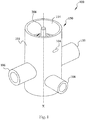
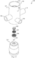
- Fig. 1 is a stereogram of a vehicle thermostat 100 according to one embodiment of the present application; and Fig. 2A and Fig. 2B are an exploded view and an axial sectional view of the vehicle thermostat 100 in Fig. 1 , respectively.
- the vehicle thermostat 100 includes a housing 150.
- the housing 150 comprises a housing body 103 and communicating pipes 106, 108 and 110.
- the housing body 103 is generally cylindrical and has an axis X.
- the communicating pipes 106, 108 and 110 are disposed on the housing body 103.
- the communicating pipe 106 and the communicating pipe 110 are symmetrically disposed on the left side and right side of the housing 150 with respect to the housing body 103, respectively.
- the communicating pipe 108 is disposed on the front side of the housing body 103.
- the vehicle thermostat 100 also includes a rotating shaft 208 and a hollow valve body 210 disposed in the housing 150.
- the rotating shaft 208 and the housing body 103 share the same axis X, and the rotating shaft 208 can rotate around the axis X.
- the hollow valve body 210 is connected to the rotating shaft 208. When the rotating shaft 208 rotates, the hollow valve body 210 can rotate together with the rotating shaft 208.
- the hollow valve body 210 is provided with two holes (not shown). By controlling the rotation of the valve body 210, the two holes can be controlled to align with two of the communicating pipes 106, 108 and 110, so that a cooling liquid can be selectively guided, by the vehicle thermostat 100, from an internal combustion engine via a bypass or radiator back to the internal combustion engine.
- the rotation of the valve body 210 is enabled by a driving device (not shown).
- a partition board 112 is arranged in the housing 150.
- the partition board 112 is an annular plate arranged in the housing 150 and has an opening 125 through which the rotating shaft 208 passes (see also Fig. 3 ).
- the partition board 112 divides the space in the housing 150 into an upper chamber 114 and a lower chamber 116.
- the upper chamber 114 is configured to at least partially accommodate the driving device (not shown).
- the lower chamber 116 is configured to accommodate the valve body 210 (see Fig. 2B for details). After the hollow valve body 210 is installed in the lower chamber 116 of the housing 150, the rotating shaft 208 extends from the lower chamber 116 through the opening 125 of the partition board 112 into the upper chamber 114.
- the rotating shaft 208 is connected to the driving device. Since the lower chamber 116 contains the cooling liquid, a seal ring 204 and a seal ring 206 are provided between the partition board 112 and the rotating shaft 208 to prevent the cooling liquid from entering an area of a driving member located in the upper chamber 114 from the lower chamber 116.
- Fig. 3 is an axial sectional view of the housing 150 in Fig. 1 .
- the housing 150 is a cylinder with a closed lower part and an open upper part.
- the lower part of the housing 150 may be closed by a closing plate 304.
- the bottom of the housing 150 may not be closed, but may be used as an inflow pipe or an outflow pipe.
- the partition board 112 includes an upper surface 120 and a lower surface 122.
- a passage 104 is provided in the partition board 112. The passage 104 extends through the partition board 112 and through the housing 150 and communicates with the atmosphere outside the housing 150, so that the cooling liquid potentially leaking from a seal structure 610 may not directly enter the upper chamber 114.
- the partition board 112 is provided with a supporting part 132 which is arranged around the opening 125 of the partition board 112 and extends upward from the upper surface 120 of the partition board 112.
- An upper end of the supporting part 132 is provided with a blocking part 142.
- a bearing 202 (as shown in Fig. 2B ) is provided between the supporting part 132 and the rotating shaft 208, and the blocking part 142 may restrict the upward axial movement of the bearing 202.
- the seal ring 204 is installed between the supporting part 132 and the rotating shaft 208 (as shown in Fig. 2B ).
- the partition board 112 is also provided with a supporting part 134, which is a cylinder formed by extending downward from the lower surface 122 of the partition board 112 at a distance from the opening 125.
- a blocking part 144 is formed on the portion between the supporting part 134 and the opening 125 of the partition board 112.
- the seal ring 206 is installed between the supporting part 134 and the rotating shaft 208 (as shown in Fig. 2B ), and the blocking part 144 may restrict the upward axial movement of the seal ring 206 (as shown in Fig. 2B ).
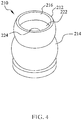
- Fig. 4 is a stereogram of the valve body 210 in Fig. 2A .
- the valve body 210 includes an upper valve body 212 and a lower valve body 214, and the upper valve body 212 and the lower valve body 214 are in a partial spherical segment shape.
- the valve body 210 also includes a division board 222 disposed at the junction of the upper valve body 212 and the lower valve body 214, thereby dividing a cavity in the valve body 210 into an upper cavity 216 and a lower cavity 218 (not shown, see Fig. 7A to Fig. 7B for details).
- the division board 222 is provided with a hole 224 so that the rotating shaft 208 can pass through the division board 222.
- the upper cavity 216 is configured to accommodate the supporting part 134 and the seal ring 206 (as shown in Fig. 2B ).
- the lower valve body 214 has the aforementioned hole (not shown) to fluidly communicate the valve body 210 with the lower chamber 116 in the housing 150.
- the rotating shaft 208 may or may not be integrally formed with the valve body 210, for example, by insert injection molding. Instead of including the two spherical portions as shown in Fig. 4 , the valve body 210 may include only one spherical portion.
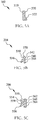
- Fig. 5A and Fig. 5B are an axial sectional view of the bearing 202 and an axial sectional view of the seal ring 204 according to one embodiment of the present application, respectively.
- the bearing 202 has a hollow cylindrical shape with an inner wall 510 and an outer wall 520.
- the inner wall 510 is in contact with the rotating shaft 208.
- a lower end of the inner wall 510 is fitted with a stepped part 602 (see Fig. 6 ) on the rotating shaft 208 to restrict the bearing 202 from sliding down in an axial direction.
- a lower end of the outer wall 520 is provided with a protrusion 522.
- the seal ring 204 has an outer wall 540 and an inner wall 530.
- the outer wall 540 includes external ribs 542 and 544, and the external ribs 542 and 544 are disposed along a circumferential direction of the outer wall 540.
- the inner wall 530 includes a seal contact part 534 extending inwards from the inner wall 530, the seal contact part 534 is disposed along a circumferential direction of the inner wall 530, and the seal contact part 534 extends obliquely downwards from the inner wall 530 so that an axial section of the seal ring 204 is a Y-shaped structure.
- a hook component 570 is provided at an upper end of the seal ring 204, and the hook component 570 is disposed along a circumferential direction of the inner wall 530.
- the hook component 570 can be engaged with the protrusion 522 of the bearing 202, thereby engaging the seal ring 204 with the bearing 202 (as shown in Fig. 6 ). In this way, the seal ring 204 may be prevented from sliding downwards along an axial direction by the bearing 202.
- the bearing 202 and the seal ring 204 may have various configurations.
- the outer wall 540 may include one or more external ribs, and the external ribs are disposed along a circumferential direction of the outer wall 540.
- the inner wall 530 may include one or more seal contact parts extending inwards from the inner wall 530, and the seal contact parts are disposed along a circumferential direction of the inner wall 530.
- Fig. 5C is an axial sectional view of the seal ring 206 according to one embodiment of the present application.
- the seal ring 206 has an outer wall 560 and an inner wall 550.
- the outer wall 560 includes external ribs 562 and 564, and the external ribs 562 and 564 are disposed along a circumferential direction of the outer wall 560.
- the inner wall 550 includes seal contact parts 554 and 556 extending inwards from the inner wall 550, and the seal contact parts 554 and 556 are disposed along a circumferential direction of the inner wall 550, wherein one seal contact part 554 extends obliquely upwards from the inner wall 550, and the other seal contact part 556 extends obliquely downwards from the inner wall 550 so that an axial section of the seal ring 206 is a K-shaped structure.
- a recessed part 558 is provided between the two seal contact parts 554 and 556, and the recessed part 558 may be configured to receive a lubricant.
- the outer wall 560 may also have more different configurations.
- the outer wall 560 may include one or more external ribs, and the external ribs are disposed along a circumferential direction of the outer wall 560.
- the inner wall 550 may include even more seal contact parts extending inwards from the inner wall 550, and the seal contact parts are disposed along a circumferential direction of the inner wall 550.
- the seal ring 204 and the seal ring 206 in the application are made of an elastic material.
- the elastic material is ethylene propylene diene rubber.
- the seal rings 204 and 206 may be injection molded.
- Fig. 6 is a partially enlarged view of the dashed line portion in Fig. 2B , showing seal structures 600 and 610 according to one embodiment of the application.
- the seal structure 600 is configured to form a seal between the rotating shaft 208 and the housing 150 to prevent the cooling liquid from entering an area of the driving member located in the upper chamber 114 from the lower chamber 116 and to prevent gas from entering the area of the driving member located in the upper chamber 114 from the gas passage 104 of the partition board 112 of the housing 150.
- the seal structure 600 includes the seal ring 204 and a structure mating with the seal ring 204.
- the inner wall 510 of the bearing 202 abuts against the rotating shaft 208, an inner side of a lower end of the bearing 202 is engaged with the stepped part 602 on the rotating shaft 208, and the outer wall 520 of the bearing 202 abuts against the blocking part 142 of the housing 150.
- the axial and radial movements of the bearing 202 are restricted by the above-described engagement, so that the bearing 202 is limited between the rotating shaft 208 and the blocking part 142 of the housing 150.
- the seal ring 204 is sandwiched between the bearing 202 and the supporting part 132 of the housing 150 so that the external ribs 542 and 544 on the outer wall 540 of the seal ring 204 abut against the supporting part 132, and the seal contact part 534 of the seal ring 204 abuts against the rotating shaft 208, and thus the seal ring 204 cannot move radially.
- the hook component 570 of the seal ring 204 is engaged with the protrusion 522 of the bearing 202, thereby restricting the seal ring 204 from sliding down in the axial direction. As a result, there is no liquid passage between the rotating shaft 208 and the partition board 112 of the housing 150 anymore, thereby enabling the sealed separation of the upper chamber 114 from the passage 104.
- the seal ring 204 When the seal ring 204 is installed in the assembly position shown in Fig. 6 , since the seal ring 204 is made of an elastic material, the external ribs 542 and 544 are squeezed and deformed to generate friction, and so is the seal contact part 534. Since the friction force on the seal contact part 534 is smaller than the friction force on the external ribs 542 and 544, when the rotating shaft 208 in the vehicle thermostat 100 rotates, the seal ring 204 may not rotate along with the rotating shaft 208.
- the bearing 202, the seal ring 204 and the rotating shaft 208 may be assembled in the following order: first, engaging the seal ring 204 with the bearing 202, followed by mounting them to the housing 150, and then inserting the rotating shaft 208.
- the seal ring 204 may also first be engaged with the bearing 202, and then sleeved onto the rotating shaft 208, and then thus assembled seal ring 204 may be installed into the housing 150, which more advantageously enables mass automatic assembly.
- the seal structure 610 is also configured to form a seal between the rotating shaft 208 and the housing 105 to prevent the cooling liquid in the valve body 210 from entering the gas passage 104 of the housing 105 and keep gas from entering the valve body 210 from the gas passage 104, and further stop the cooling liquid from entering the area of the driving member located in the upper chamber 114 from the lower chamber 116.
- the seal structure 610 includes the seal ring 206 and a structure mating with the seal ring 206.
- the seal contact parts 554 and 556 on the inner wall 550 of the seal ring 206 abut against the rotating shaft 208, and the external ribs 562 and 564 on the outer wall 560 of the seal ring 206 abut against the supporting part 134 to restrict the radial movement of the seal ring 206.
- An upper end of the seal ring 206 abuts against the blocking part 144 of the housing 150, thereby limiting the seal ring 206 between the rotating shaft 208 and the supporting part 134 of the housing 150. In this way, there is no fluid passage between the rotating shaft 208 and the housing 150 anymore due to the presence of the seal ring 206, thus enabling the seal between the rotating shaft 208 and the housing 150.
- the seal ring 206 is also made of an elastic material, so when the seal ring 206 is installed in the assembly position as shown in Fig. 6 , the external ribs 562 and 564 are squeezed and deformed to generate friction, and so are the seal contact parts 554 and 556. Since the friction force on the seal contact parts 554 and 556 is smaller than the friction force on the external ribs 562 and 564, the seal ring 206 may not rotate along with the rotating shaft 208 when the rotating shaft 208 in the vehicle thermostat 100 rotates.
- the axial section of the seal ring 206 is configured to be a K-shaped structure such that the recessed part 558 is provided between the two seal contact parts 554 and 556, and the recessed part 558 is configured to receive a lubricant, thereby lubricating the rotating shaft 208.
- the seal ring 206 and the rotating shaft 208 may be assembled in the following order: first, engaging the seal ring 204 with the bearing 202, followed by mounting them to the housing 150, and then inserting the rotating shaft 208.
- the seal ring 204 may also first be engaged with the bearing 202, and then sleeved onto the rotating shaft 208, and then thus assembled seal ring 204 may be installed into the housing 150, which more advantageously enables mass automatic assembly.
- Fig. 7A is an axial sectional view of a vehicle thermostat 100 according to another embodiment of the present application, showing a seal structure having adjustment contact parts.
- a top surface 710 of the division board 222 of the valve body 210 i.e., the bottom of the cavity 216) is provided with the adjustment contact part 702 so that the seal ring 206 contacts the adjustment contact part 702 when sliding down the rotating shaft 208, so as to be supported.
- the adjustment contact part 702 protrudes from the bottom of the cavity 216 of the valve body 210 (i.e., the top surface 710 of the division board 222), and an adjustment space 704 is provided between a top portion of the adjustment contact part 702 and a lower portion of the seal ring 206.
- Fig. 7B is an axial sectional view of a vehicle thermostat 100 according to yet another embodiment of the present application, with an additional gasket 706 on the basis of Fig. 7A .
- the adjustment contact part 702 includes several arms protruding from the bottom of the cavity 216 of the valve body 210 (i.e., the top surface 710 of the division board 222).
- the gasket 706 is provided between the adjustment contact part 702 and the seal ring 206, so that the seal ring 206 may be better supported when sliding down the rotating shaft 208.
Landscapes
- Engineering & Computer Science (AREA)
- General Engineering & Computer Science (AREA)
- Mechanical Engineering (AREA)
- Manufacturing & Machinery (AREA)
- Sealing Devices (AREA)
Abstract
Description
- The present application relates to a seal ring and seal structure, and in particular to a seal ring and seal structure for a rotating shaft. The seal ring and the seal structure in the application may be used in the field of general machinery, and in particular in the field of thermostats of internal combustion engines.
- Thermostats for internal combustion engines generally comprise a housing and a hollow valve body disposed within the housing. The housing is equipped with at least three ports, namely, an internal combustion engine port for communicating with an internal combustion engine cooling system, a radiator port for communicating with a radiator, and a bypass port for communicating with a bypass. The hollow valve body is driven by a driving device to rotate around a rotating shaft in the housing. The hollow valve body is provided with at least one hole which can selectively communicate with one or more coolant connection ports of the housing by the rotation of the hollow valve body so that the coolant can be selectively guided by the thermostat from the internal combustion engine, via the bypass or radiator back to the internal combustion engine. Since the rotating shaft of the hollow valve body is connected with the driving device and the rotating shaft of the hollow valve body is in the coolant environment, it is necessary to provide a shaft seal between the rotating shaft of the hollow valve body and the driving device to prevent the coolant from entering the driving device along the rotating shaft and thus to protect the driving device against short-circuit, corrosion, wear or the like due to erosion by the coolant.
- A traditional seal ring for rotating shafts generally uses a skeleton oil seal which includes a metal skeleton and rubber. Specifically, the skeleton oil seal has a layer of rubber externally wrapped around the metal skeleton. The metal skeleton provides tension to secure the seal ring at a sealing position. However, due to use of the structure as combined the metal skeleton with rubber, the traditional seal ring has higher material costs and manufacturing costs, and the defective rate of finished products is also higher. Besides, the configuration of the metal skeleton requires very high installation accuracy during assembly. This is because, during assembly, since the metal skeleton provides the tension for fixing to the housing, the metal skeleton must be already positioned at the installation position before installing the rotating shaft, and then the rotating shaft is inserted therein. However, the skeleton oil seal which has already been positioned at the installation position requires that the rotating shaft must be accurately centered, otherwise the rubber contacting the rotating shaft would be stressed unevenly in various positions during installation of the rotating shaft, which may damage the seal ring and reduce the sealing effect and service life of the seal ring.
- Therefore, there is a need for a new seal ring and seal structure which can not only optimize the assembly sequence for miniaturization and mass automatic assembly with reduced costs and improved yield rates, but also improve the sealing effect and service life of the seal ring.
- Exemplary embodiments of the present application may solve at least some of the above problems.
- According to a first aspect of the application, the application provides a seal ring for sealing a rotating shaft, wherein the seal ring has an outer wall and an inner wall; the outer wall includes one or more external ribs, and the external ribs are disposed along a circumferential direction of the outer wall; the inner wall includes one or more seal contact parts extending inwards from the inner wall, and the seal contact parts are disposed along a circumferential direction of the inner wall; and the seal ring is made of an elastic material.
- According to the seal ring described above, two of the seal contact parts are provided, wherein one of the seal contact parts extends obliquely upwards from the inner wall, and the other of the seal contact parts extends obliquely downwards from the inner wall.
- According to the seal ring described above, an axial section of the seal ring is a K-shaped structure, and a recessed part is provided between the two seal contact parts, the recessed part being configured to receive a lubricant.
- According to the seal ring described above, one of the seal contact parts is provided, wherein the seal contact part extends obliquely downwards from the inner wall so that an axial section of the seal ring is a Y-shaped structure; and a hook component is provided at an upper end of the seal ring, the hook component being disposed along a circumferential direction of the inner wall for restricting the seal ring from sliding downwards along an axial direction.
- According to the seal ring described above, the elastic material is ethylene propylene diene rubber.
- According to the seal ring described above, the seal ring is injection molded.
- According to a second aspect of the application, the application provides a seal structure, and the seal structure comprises:
- a seal ring having an outer wall and an inner wall; the outer wall including one or more external ribs, the external ribs being disposed along a circumferential direction of the outer wall; the inner wall including one or more seal contact parts extending inwards from the inner wall, the seal contact parts being disposed along a circumferential direction of the inner wall; wherein the seal ring is made of an elastic material;
- a valve body, a downwardly recessed cavity being provided at a top portion of the valve body; and
- a rotating shaft, the rotating shaft passing through the cavity, the seal ring being disposed at the rotating shaft in the cavity;
- According to the seal structure described above, the adjustment contact part protrudes from the bottom portion of the cavity of the valve body.
- According to a third aspect of the application, the application provides a seal structure, and the seal structure comprises:
- a seal ring having an outer wall and an inner wall; the outer wall including one or more external ribs, the external ribs being disposed along a circumferential direction of the outer wall; the inner wall including one or more seal contact parts extending inwards from the inner wall, the seal contact parts being disposed along a circumferential direction of the inner wall; wherein the seal ring is made of an elastic material; wherein one of the seal contact parts is provided, and the seal contact part extends obliquely downwards from the inner wall so that an axial section of the seal ring is a Y-shaped structure; and a hook component is provided at an upper end of the seal ring, the hook component being disposed along a circumferential direction of the inner wall;
- a rotating shaft on which the seal ring is disposed; and
- a bearing disposed on the rotating shaft, a protrusion being provided at a lower end of the bearing, the protrusion being configured to be engaged with the hook component to restrict the seal ring from sliding downwards along an axial direction.
- According to the two seal structures described above, a passage is provided between the seal ring in the seal structure according to the second aspect and the seal ring in the seal structure according to the third aspect.
- The seal ring and seal structure according to the application can not only optimize the assembly sequence for miniaturization and mass automatic assembly with reduced costs and improved yield rates, but also improve the sealing effect and service life of the seal ring.
- Other features, advantages and embodiments of the present application may be set forth or become apparent by considering the following detailed description, drawings and claims. In addition, it should be understood that both the above summary of the application and the following detailed description are intended to be exemplary and to provide further explanation rather than limiting the scope of the claimed application. However, the detailed description and specific examples only indicate the preferred embodiments of the present application. Various changes and modifications within the spirit and scope of the application will become apparent to those skilled in the art from the detailed description.
- These and other features and advantages of the present application may be better understood by reading the following detailed description with reference to the accompanying drawings, in which like reference numerals refer to like parts throughout the drawings, and in which:
- Fig. 1
- is a stereogram of a vehicle thermostat according to one embodiment of the present application;
- Fig. 2A
- is an exploded view of the vehicle thermostat in
Fig. 1 ; - Fig. 2B
- is an axial sectional view of the vehicle thermostat in
Fig. 1 ; - Fig. 3
- is an axial sectional view of the housing in
Fig. 1 ; - Fig. 4
- is a stereogram of the valve body in
Fig. 1 ; - Fig. 5A
- is an axial sectional view of a bearing according to one embodiment of the present application;
- Fig. 5B
- is an axial sectional view of a seal ring according to one embodiment of the present application;
- Fig. 5C
- is an axial sectional view of a seal ring according to one embodiment of the present application;
- Fig. 6
- is a partially enlarged view of
Fig. 2B , showing a seal structure according to one embodiment of the present application; - Fig. 7A
- is an axial sectional view of a vehicle thermostat according to another embodiment of the present application, showing a seal structure having adjustment contact parts;
- Fig. 7B
- is an axial sectional view of a vehicle thermostat according to yet another embodiment of the present application, with an additional gasket on the basis of
Fig. 7A . - Various embodiments of the present application will now be described with reference to the accompanying drawings that form a part of the specification. It should be understood that although directional terms such as "front," "back," "up," "down," "left," "right" or other directional or orientational descriptions are used in the application to describe various exemplary structural parts and elements of the application, these terms are used herein only for convenience of description and are determined based on the exemplary orientations shown in the drawings. Since the embodiments disclosed herein may be arranged in different directions, these directional terms are for illustration only and should not be taken as limitations. In the following drawings, the same parts use the same reference numerals, and similar parts use similar reference numerals.
- The seal ring and seal structure of the application can be used in the field of general machinery. In order to better embody the practical application of the seal ring and seal structure of the present application, the following description will take the vehicle thermostat as an example.
-
Fig. 1 is a stereogram of avehicle thermostat 100 according to one embodiment of the present application; andFig. 2A andFig. 2B are an exploded view and an axial sectional view of thevehicle thermostat 100 inFig. 1 , respectively. - As shown in
Fig. 1 ,Fig. 2A andFig. 2B , thevehicle thermostat 100 includes ahousing 150. Thehousing 150 comprises ahousing body 103 and communicatingpipes housing body 103 is generally cylindrical and has an axis X. The communicatingpipes housing body 103. Specifically, the communicatingpipe 106 and the communicatingpipe 110 are symmetrically disposed on the left side and right side of thehousing 150 with respect to thehousing body 103, respectively. The communicatingpipe 108 is disposed on the front side of thehousing body 103. - The
vehicle thermostat 100 also includes arotating shaft 208 and ahollow valve body 210 disposed in thehousing 150. Therotating shaft 208 and thehousing body 103 share the same axis X, and therotating shaft 208 can rotate around the axis X. Thehollow valve body 210 is connected to therotating shaft 208. When therotating shaft 208 rotates, thehollow valve body 210 can rotate together with therotating shaft 208. Thehollow valve body 210 is provided with two holes (not shown). By controlling the rotation of thevalve body 210, the two holes can be controlled to align with two of the communicatingpipes vehicle thermostat 100, from an internal combustion engine via a bypass or radiator back to the internal combustion engine. The rotation of thevalve body 210 is enabled by a driving device (not shown). - Referring to
Fig. 2B , apartition board 112 is arranged in thehousing 150. Thepartition board 112 is an annular plate arranged in thehousing 150 and has anopening 125 through which therotating shaft 208 passes (see alsoFig. 3 ). Thepartition board 112 divides the space in thehousing 150 into anupper chamber 114 and alower chamber 116. Theupper chamber 114 is configured to at least partially accommodate the driving device (not shown). Thelower chamber 116 is configured to accommodate the valve body 210 (seeFig. 2B for details). After thehollow valve body 210 is installed in thelower chamber 116 of thehousing 150, therotating shaft 208 extends from thelower chamber 116 through theopening 125 of thepartition board 112 into theupper chamber 114. In theupper chamber 114, therotating shaft 208 is connected to the driving device. Since thelower chamber 116 contains the cooling liquid, aseal ring 204 and aseal ring 206 are provided between thepartition board 112 and therotating shaft 208 to prevent the cooling liquid from entering an area of a driving member located in theupper chamber 114 from thelower chamber 116. -
Fig. 3 is an axial sectional view of thehousing 150 inFig. 1 . As shown inFig. 3 , thehousing 150 is a cylinder with a closed lower part and an open upper part. - Specifically, the lower part of the
housing 150 may be closed by aclosing plate 304. The bottom of thehousing 150 may not be closed, but may be used as an inflow pipe or an outflow pipe. Thepartition board 112 includes anupper surface 120 and alower surface 122. Apassage 104 is provided in thepartition board 112. Thepassage 104 extends through thepartition board 112 and through thehousing 150 and communicates with the atmosphere outside thehousing 150, so that the cooling liquid potentially leaking from aseal structure 610 may not directly enter theupper chamber 114. Thepartition board 112 is provided with a supportingpart 132 which is arranged around theopening 125 of thepartition board 112 and extends upward from theupper surface 120 of thepartition board 112. An upper end of the supportingpart 132 is provided with a blockingpart 142. A bearing 202 (as shown inFig. 2B ) is provided between the supportingpart 132 and therotating shaft 208, and the blockingpart 142 may restrict the upward axial movement of thebearing 202. Theseal ring 204 is installed between the supportingpart 132 and the rotating shaft 208 (as shown inFig. 2B ). Thepartition board 112 is also provided with a supportingpart 134, which is a cylinder formed by extending downward from thelower surface 122 of thepartition board 112 at a distance from theopening 125. A blockingpart 144 is formed on the portion between the supportingpart 134 and theopening 125 of thepartition board 112. Theseal ring 206 is installed between the supportingpart 134 and the rotating shaft 208 (as shown inFig. 2B ), and the blockingpart 144 may restrict the upward axial movement of the seal ring 206 (as shown inFig. 2B ). -
Fig. 4 is a stereogram of thevalve body 210 inFig. 2A . As shown inFig. 4 , thevalve body 210 includes anupper valve body 212 and alower valve body 214, and theupper valve body 212 and thelower valve body 214 are in a partial spherical segment shape. Thevalve body 210 also includes adivision board 222 disposed at the junction of theupper valve body 212 and thelower valve body 214, thereby dividing a cavity in thevalve body 210 into anupper cavity 216 and a lower cavity 218 (not shown, seeFig. 7A to Fig. 7B for details). Thedivision board 222 is provided with ahole 224 so that therotating shaft 208 can pass through thedivision board 222. Theupper cavity 216 is configured to accommodate the supportingpart 134 and the seal ring 206 (as shown inFig. 2B ). Thelower valve body 214 has the aforementioned hole (not shown) to fluidly communicate thevalve body 210 with thelower chamber 116 in thehousing 150. Therotating shaft 208 may or may not be integrally formed with thevalve body 210, for example, by insert injection molding. Instead of including the two spherical portions as shown inFig. 4 , thevalve body 210 may include only one spherical portion. -
Fig. 5A and Fig. 5B are an axial sectional view of thebearing 202 and an axial sectional view of theseal ring 204 according to one embodiment of the present application, respectively. As shown inFig. 5A , thebearing 202 has a hollow cylindrical shape with aninner wall 510 and anouter wall 520. Theinner wall 510 is in contact with therotating shaft 208. A lower end of theinner wall 510 is fitted with a stepped part 602 (seeFig. 6 ) on therotating shaft 208 to restrict the bearing 202 from sliding down in an axial direction. A lower end of theouter wall 520 is provided with aprotrusion 522. - As shown in
Fig. 5B , theseal ring 204 has anouter wall 540 and aninner wall 530. Theouter wall 540 includesexternal ribs external ribs outer wall 540. Theinner wall 530 includes aseal contact part 534 extending inwards from theinner wall 530, theseal contact part 534 is disposed along a circumferential direction of theinner wall 530, and theseal contact part 534 extends obliquely downwards from theinner wall 530 so that an axial section of theseal ring 204 is a Y-shaped structure. Ahook component 570 is provided at an upper end of theseal ring 204, and thehook component 570 is disposed along a circumferential direction of theinner wall 530. Thehook component 570 can be engaged with theprotrusion 522 of thebearing 202, thereby engaging theseal ring 204 with the bearing 202 (as shown inFig. 6 ). In this way, theseal ring 204 may be prevented from sliding downwards along an axial direction by thebearing 202. - It should be noted that the
bearing 202 and theseal ring 204 may have various configurations. As an example, theouter wall 540 may include one or more external ribs, and the external ribs are disposed along a circumferential direction of theouter wall 540. As another example, theinner wall 530 may include one or more seal contact parts extending inwards from theinner wall 530, and the seal contact parts are disposed along a circumferential direction of theinner wall 530. -
Fig. 5C is an axial sectional view of theseal ring 206 according to one embodiment of the present application. As shown inFig. 5C , theseal ring 206 has anouter wall 560 and aninner wall 550. Theouter wall 560 includesexternal ribs external ribs outer wall 560. Theinner wall 550 includesseal contact parts inner wall 550, and theseal contact parts inner wall 550, wherein oneseal contact part 554 extends obliquely upwards from theinner wall 550, and the otherseal contact part 556 extends obliquely downwards from theinner wall 550 so that an axial section of theseal ring 206 is a K-shaped structure. A recessedpart 558 is provided between the twoseal contact parts part 558 may be configured to receive a lubricant. - It should be noted that the
outer wall 560 may also have more different configurations. As an example, theouter wall 560 may include one or more external ribs, and the external ribs are disposed along a circumferential direction of theouter wall 560. As another example, theinner wall 550 may include even more seal contact parts extending inwards from theinner wall 550, and the seal contact parts are disposed along a circumferential direction of theinner wall 550. - The
seal ring 204 and theseal ring 206 in the application are made of an elastic material. For example, the elastic material is ethylene propylene diene rubber. In order to realize mass production at low cost, the seal rings 204 and 206 may be injection molded. -
Fig. 6 is a partially enlarged view of the dashed line portion inFig. 2B , showingseal structures 600 and 610 according to one embodiment of the application. As shown inFig. 6 , the seal structure 600 is configured to form a seal between therotating shaft 208 and thehousing 150 to prevent the cooling liquid from entering an area of the driving member located in theupper chamber 114 from thelower chamber 116 and to prevent gas from entering the area of the driving member located in theupper chamber 114 from thegas passage 104 of thepartition board 112 of thehousing 150. The seal structure 600 includes theseal ring 204 and a structure mating with theseal ring 204. Specifically, theinner wall 510 of thebearing 202 abuts against therotating shaft 208, an inner side of a lower end of thebearing 202 is engaged with the steppedpart 602 on therotating shaft 208, and theouter wall 520 of thebearing 202 abuts against the blockingpart 142 of thehousing 150. The axial and radial movements of thebearing 202 are restricted by the above-described engagement, so that thebearing 202 is limited between therotating shaft 208 and the blockingpart 142 of thehousing 150. Theseal ring 204 is sandwiched between the bearing 202 and the supportingpart 132 of thehousing 150 so that theexternal ribs outer wall 540 of theseal ring 204 abut against the supportingpart 132, and theseal contact part 534 of theseal ring 204 abuts against therotating shaft 208, and thus theseal ring 204 cannot move radially. Thehook component 570 of theseal ring 204 is engaged with theprotrusion 522 of thebearing 202, thereby restricting theseal ring 204 from sliding down in the axial direction. As a result, there is no liquid passage between therotating shaft 208 and thepartition board 112 of thehousing 150 anymore, thereby enabling the sealed separation of theupper chamber 114 from thepassage 104. - When the
seal ring 204 is installed in the assembly position shown inFig. 6 , since theseal ring 204 is made of an elastic material, theexternal ribs seal contact part 534. Since the friction force on theseal contact part 534 is smaller than the friction force on theexternal ribs rotating shaft 208 in thevehicle thermostat 100 rotates, theseal ring 204 may not rotate along with therotating shaft 208. - The
bearing 202, theseal ring 204 and therotating shaft 208 may be assembled in the following order: first, engaging theseal ring 204 with thebearing 202, followed by mounting them to thehousing 150, and then inserting therotating shaft 208. However, for theseal ring 204 in the application, theseal ring 204 may also first be engaged with thebearing 202, and then sleeved onto therotating shaft 208, and then thus assembledseal ring 204 may be installed into thehousing 150, which more advantageously enables mass automatic assembly. - Next, the
seal structure 610 will be described. As shown inFig. 6 , theseal structure 610 is also configured to form a seal between therotating shaft 208 and the housing 105 to prevent the cooling liquid in thevalve body 210 from entering thegas passage 104 of the housing 105 and keep gas from entering thevalve body 210 from thegas passage 104, and further stop the cooling liquid from entering the area of the driving member located in theupper chamber 114 from thelower chamber 116. Theseal structure 610 includes theseal ring 206 and a structure mating with theseal ring 206. Specifically, theseal contact parts inner wall 550 of theseal ring 206 abut against therotating shaft 208, and theexternal ribs outer wall 560 of theseal ring 206 abut against the supportingpart 134 to restrict the radial movement of theseal ring 206. An upper end of theseal ring 206 abuts against the blockingpart 144 of thehousing 150, thereby limiting theseal ring 206 between therotating shaft 208 and the supportingpart 134 of thehousing 150. In this way, there is no fluid passage between therotating shaft 208 and thehousing 150 anymore due to the presence of theseal ring 206, thus enabling the seal between therotating shaft 208 and thehousing 150. - Like the
seal ring 204, theseal ring 206 is also made of an elastic material, so when theseal ring 206 is installed in the assembly position as shown inFig. 6 , theexternal ribs seal contact parts seal contact parts external ribs seal ring 206 may not rotate along with therotating shaft 208 when therotating shaft 208 in thevehicle thermostat 100 rotates. As an example, as described above, the axial section of theseal ring 206 is configured to be a K-shaped structure such that the recessedpart 558 is provided between the twoseal contact parts part 558 is configured to receive a lubricant, thereby lubricating therotating shaft 208. - Similar to the
seal ring 204, theseal ring 206 and therotating shaft 208 may be assembled in the following order: first, engaging theseal ring 204 with thebearing 202, followed by mounting them to thehousing 150, and then inserting therotating shaft 208. However, for theseal ring 204 in the application, theseal ring 204 may also first be engaged with thebearing 202, and then sleeved onto therotating shaft 208, and then thus assembledseal ring 204 may be installed into thehousing 150, which more advantageously enables mass automatic assembly. -
Fig. 7A is an axial sectional view of avehicle thermostat 100 according to another embodiment of the present application, showing a seal structure having adjustment contact parts. As shown inFig. 7A , atop surface 710 of thedivision board 222 of the valve body 210 (i.e., the bottom of the cavity 216) is provided with theadjustment contact part 702 so that theseal ring 206 contacts theadjustment contact part 702 when sliding down therotating shaft 208, so as to be supported. As one embodiment, theadjustment contact part 702 protrudes from the bottom of thecavity 216 of the valve body 210 (i.e., thetop surface 710 of the division board 222), and anadjustment space 704 is provided between a top portion of theadjustment contact part 702 and a lower portion of theseal ring 206. -
Fig. 7B is an axial sectional view of avehicle thermostat 100 according to yet another embodiment of the present application, with anadditional gasket 706 on the basis ofFig. 7A . As shown inFig. 7B , theadjustment contact part 702 includes several arms protruding from the bottom of thecavity 216 of the valve body 210 (i.e., thetop surface 710 of the division board 222). Thegasket 706 is provided between theadjustment contact part 702 and theseal ring 206, so that theseal ring 206 may be better supported when sliding down therotating shaft 208. - Although only some features of the application have been illustrated and described herein, many modifications and variations will occur to those skilled in the art. It is therefore to be understood that the appended claims are intended to cover all such modifications and variations as fall within the true spirit of the application.
Claims (9)
- A seal ring (204, 206) for sealing a rotating shaft (208), characterized in that:- the seal ring (204, 206) has an outer wall (540, 560) and an inner wall (530, 550);- the outer wall (540, 560) includes one or more external ribs (542, 544, 562, 564), the external ribs (542, 544, 562, 564) being disposed along a circumferential direction of the outer wall (540, 560); and- the inner wall (530, 550) includes one or more seal contact parts (534, 554, 556) extending inwards from the inner wall (530, 550), the seal contact parts (534, 554, 556) being disposed along a circumferential direction of the inner wall (530, 550);wherein the seal ring (204, 206) is made of an elastic material.
- The seal ring (206) according to claim 1,
characterized in that
two of the seal contact parts (554, 556) are provided, wherein one of the seal contact parts extends obliquely upwards from the inner wall (550), and the other of the seal contact parts extends obliquely downwards from the inner wall (550). - The seal ring (206) according to claim 2,
characterized in that
an axial section of the seal ring (206) is a K-shaped structure, and a recessed part (558) is provided between the two seal contact parts (554, 556), the recessed part (558) being configured to receive a lubricant. - The seal ring (204) according to claim 1,
characterized in that
one of the seal contact parts (534) is provided, wherein the seal contact part (534) extends obliquely downwards from the inner wall (530) so that an axial section of the seal ring (204) is a Y-shaped structure; and a hook component (570) is provided at an upper end of the seal ring (204), the hook component (570) being disposed along a circumferential direction of the inner wall (530) for restricting the seal ring (204) from sliding downwards along an axial direction. - The seal ring (204, 206) according to one of the preceding claims,
characterized in that
the elastic material is ethylene propylene diene rubber. - The seal ring (204, 206) according to one of the preceding claims,
characterized in that
the seal ring (204, 206) is injection molded. - A seal structure (610),
characterized in that
the seal structure (610) comprises:- a seal ring (206) having an outer wall (560) and an inner wall (550);- the outer wall (560) including one or more external ribs (562, 564), the external ribs (562, 564) being disposed along a circumferential direction of the outer wall (560);- the inner wall (550) including one or more seal contact parts (554, 556) extending inwards from the inner wall (550), the seal contact parts (554, 556) being disposed along a circumferential direction of the inner wall (550);wherein, the seal ring (206) is made of an elastic material;- a valve body (210), a downwardly recessed cavity (216) being provided at- a top portion of the valve body (210); and- a rotating shaft (208), the rotating shaft (208) passing through the cavity (216), the seal ring (204, 206) being disposed at the rotating shaft (208);wherein an adjustment contact part (702) is provided at a bottom portion of the cavity (216) of the valve body (210), and an adjustment space (704) is provided between the adjustment contact part (702) and a lower portion of the seal ring (206). - The seal structure (600) according to claim 7,
characterized in that
the adjustment contact part (702) protrudes from the bottom portion of the cavity (216) of the valve body (210). - A seal structure (600),
characterized in that
the seal structure (600) comprises:- a seal ring (204) having an outer wall (540) and an inner wall (530);- the outer wall (540) including one or more external ribs (542, 544), the external ribs (542, 544) being disposed along a circumferential direction of the outer wall (540);- the inner wall (530) including one or more seal contact parts (534) extending inwards from the inner wall (530), the seal contact part (534) being disposed along a circumferential direction of the inner wall (530);wherein the seal ring (204) is made of an elastic material;
wherein one of the seal contact parts (534) is provided, and the seal contact part (534) extends obliquely downwards from the inner wall (530) so that an axial section of the seal ring (204) is a Y-shaped structure; wherein a hook component (570) is provided at an upper end of the seal ring (204), and the hook component is disposed along a circumferential direction of the inner wall (530);- a rotating shaft (208) on which the seal ring (204) is disposed; and- a bearing (202) disposed on the rotating shaft (208), a protrusion (522) being provided at a lower end of the bearing (202), the protrusion (522) being configured for being engaged with the hook component (570) to restrict the seal ring (204) from sliding downwards along an axial direction.
Applications Claiming Priority (2)
| Application Number | Priority Date | Filing Date | Title |
|---|---|---|---|
| CN201711368629.1A CN109931433B (en) | 2017-12-18 | 2017-12-18 | Sealing ring and sealing assembly |
| CN201721774327.XU CN207661212U (en) | 2017-12-18 | 2017-12-18 | Sealing ring and seal assembly |
Publications (2)
| Publication Number | Publication Date |
|---|---|
| EP3499097A1 true EP3499097A1 (en) | 2019-06-19 |
| EP3499097B1 EP3499097B1 (en) | 2022-08-03 |
Family
ID=64664091
Family Applications (1)
| Application Number | Title | Priority Date | Filing Date |
|---|---|---|---|
| EP18211219.3A Active EP3499097B1 (en) | 2017-12-18 | 2018-12-10 | Seal ring and seal structure |
Country Status (2)
| Country | Link |
|---|---|
| US (1) | US11079020B2 (en) |
| EP (1) | EP3499097B1 (en) |
Families Citing this family (2)
| Publication number | Priority date | Publication date | Assignee | Title |
|---|---|---|---|---|
| JP7035955B2 (en) * | 2018-10-19 | 2022-03-15 | トヨタ自動車株式会社 | Thermostat and cooling water passage structure |
| US12281704B2 (en) * | 2023-01-13 | 2025-04-22 | Caterpillar Inc. | Seal member for joint assembly of a machine and systems, methods, and assemblies thereof |
Citations (1)
| Publication number | Priority date | Publication date | Assignee | Title |
|---|---|---|---|---|
| EP2963319A1 (en) * | 2014-07-03 | 2016-01-06 | Carl Freudenberg KG | Gasket |
Family Cites Families (15)
| Publication number | Priority date | Publication date | Assignee | Title |
|---|---|---|---|---|
| FR93039E (en) * | 1965-06-24 | 1969-01-31 | Pitner Alfred | Radial bearing with incorporated sealing. |
| FR1448274A (en) * | 1965-06-24 | 1966-08-05 | Nadella | Self-sealing radial bearing |
| US3612551A (en) * | 1969-11-06 | 1971-10-12 | Trw Inc | Bidirectional lip seal |
| FR2526896B1 (en) * | 1982-05-15 | 1986-10-10 | Skf Kugellagerfabriken Gmbh | SEALING DEVICE FOR BEARINGS |
| US6203022B1 (en) * | 1996-04-17 | 2001-03-20 | Lucas Industries Public Limited | Annular sealing element |
| FR2767374B1 (en) * | 1997-08-13 | 1999-09-17 | Hispano Suiza Sa | SEALING ARRANGEMENT FOR A TREE END |
| US6168208B1 (en) * | 1998-05-27 | 2001-01-02 | Ken Thaler | Seal for use with roof drains |
| AU2002227063B2 (en) * | 2000-12-02 | 2007-01-25 | Progressive Pneumatics, Llc | High and low temperature gas actuated cylinder |
| DE10108775B4 (en) * | 2001-02-23 | 2006-04-06 | Lucas Automotive Gmbh | master cylinder |
| US20080203672A1 (en) * | 2007-02-28 | 2008-08-28 | National Coupling Company, Inc. | Pressure-energized shaft seal |
| DE202008017339U1 (en) * | 2008-05-29 | 2009-10-01 | Rothe Erde Gmbh | sealing system |
| EP2181663B1 (en) * | 2008-10-29 | 2016-05-11 | Arthrex, Inc. | Sealing system for medical/dental handpieces |
| WO2013029903A1 (en) | 2011-09-01 | 2013-03-07 | Rausch & Pausch Gmbh | Seal, and control device having said seal |
| JP5771118B2 (en) * | 2011-10-28 | 2015-08-26 | カヤバ工業株式会社 | SEALING DEVICE AND SUSPENSION DEVICE PROVIDED WITH THIS SEALING DEVICE |
| DE102015105737A1 (en) * | 2015-04-15 | 2016-10-20 | Carl Freudenberg Kg | scraper |
-
2018
- 2018-12-04 US US16/208,723 patent/US11079020B2/en active Active
- 2018-12-10 EP EP18211219.3A patent/EP3499097B1/en active Active
Patent Citations (1)
| Publication number | Priority date | Publication date | Assignee | Title |
|---|---|---|---|---|
| EP2963319A1 (en) * | 2014-07-03 | 2016-01-06 | Carl Freudenberg KG | Gasket |
Also Published As
| Publication number | Publication date |
|---|---|
| US11079020B2 (en) | 2021-08-03 |
| EP3499097B1 (en) | 2022-08-03 |
| US20190186633A1 (en) | 2019-06-20 |
Similar Documents
| Publication | Publication Date | Title |
|---|---|---|
| EP3199848B1 (en) | Refrigerant control valve device | |
| CN112096920B (en) | Valve device | |
| US9951878B2 (en) | Thermostat valve | |
| CN109611573B (en) | Ball valve geometry and dynamic seal assembly | |
| US11079020B2 (en) | Seal ring and seal structure | |
| JP2021004670A (en) | Valve device | |
| US11162601B2 (en) | Valve device | |
| WO2021115233A1 (en) | Electric valve | |
| KR20200047691A (en) | Sealing device and assembly method | |
| US20180119826A1 (en) | Thermal management module and rotary valve thereof | |
| KR102751267B1 (en) | Sealing member for a multi direction changeover valve and multi direction changeover valve including thereof | |
| JP2020143736A (en) | Valve device | |
| US11578806B2 (en) | Seal and regulator valve | |
| JP2000046200A (en) | Butterfly valve | |
| US11378197B2 (en) | Valve | |
| CN109931433B (en) | Sealing ring and sealing assembly | |
| US9133755B2 (en) | Engine component installation feature and method | |
| CN222208972U (en) | Sealing end cover with temperature adjusting structure | |
| CN205260121U (en) | Thermolator base | |
| US11808355B2 (en) | Coolant regulator having a shaft seal | |
| EP2964912B1 (en) | Pressure support for engine valve stem seals | |
| JP7756254B2 (en) | Torque converter assembly including thrust washer | |
| EP3825586B1 (en) | Sealing device | |
| JP2012163144A (en) | Sealed structure | |
| JP7265637B2 (en) | control valve |
Legal Events
| Date | Code | Title | Description |
|---|---|---|---|
| PUAI | Public reference made under article 153(3) epc to a published international application that has entered the european phase |
Free format text: ORIGINAL CODE: 0009012 |
|
| STAA | Information on the status of an ep patent application or granted ep patent |
Free format text: STATUS: REQUEST FOR EXAMINATION WAS MADE |
|
| 17P | Request for examination filed |
Effective date: 20181210 |
|
| AK | Designated contracting states |
Kind code of ref document: A1 Designated state(s): AL AT BE BG CH CY CZ DE DK EE ES FI FR GB GR HR HU IE IS IT LI LT LU LV MC MK MT NL NO PL PT RO RS SE SI SK SM TR |
|
| AX | Request for extension of the european patent |
Extension state: BA ME |
|
| STAA | Information on the status of an ep patent application or granted ep patent |
Free format text: STATUS: EXAMINATION IS IN PROGRESS |
|
| 17Q | First examination report despatched |
Effective date: 20200408 |
|
| GRAP | Despatch of communication of intention to grant a patent |
Free format text: ORIGINAL CODE: EPIDOSNIGR1 |
|
| INTG | Intention to grant announced |
Effective date: 20220324 |
|
| STAA | Information on the status of an ep patent application or granted ep patent |
Free format text: STATUS: GRANT OF PATENT IS INTENDED |
|
| GRAS | Grant fee paid |
Free format text: ORIGINAL CODE: EPIDOSNIGR3 |
|
| GRAA | (expected) grant |
Free format text: ORIGINAL CODE: 0009210 |
|
| STAA | Information on the status of an ep patent application or granted ep patent |
Free format text: STATUS: THE PATENT HAS BEEN GRANTED |
|
| AK | Designated contracting states |
Kind code of ref document: B1 Designated state(s): AL AT BE BG CH CY CZ DE DK EE ES FI FR GB GR HR HU IE IS IT LI LT LU LV MC MK MT NL NO PL PT RO RS SE SI SK SM TR |
|
| REG | Reference to a national code |
Ref country code: AT Ref legal event code: REF Ref document number: 1508998 Country of ref document: AT Kind code of ref document: T Effective date: 20220815 Ref country code: CH Ref legal event code: EP |
|
| REG | Reference to a national code |
Ref country code: DE Ref legal event code: R096 Ref document number: 602018038695 Country of ref document: DE |
|
| REG | Reference to a national code |
Ref country code: IE Ref legal event code: FG4D |
|
| GRAP | Despatch of communication of intention to grant a patent |
Free format text: ORIGINAL CODE: EPIDOSNIGR1 |
|
| REG | Reference to a national code |
Ref country code: LT Ref legal event code: MG9D |
|
| REG | Reference to a national code |
Ref country code: NL Ref legal event code: MP Effective date: 20220803 |
|
| PG25 | Lapsed in a contracting state [announced via postgrant information from national office to epo] |
Ref country code: SE Free format text: LAPSE BECAUSE OF FAILURE TO SUBMIT A TRANSLATION OF THE DESCRIPTION OR TO PAY THE FEE WITHIN THE PRESCRIBED TIME-LIMIT Effective date: 20220803 Ref country code: RS Free format text: LAPSE BECAUSE OF FAILURE TO SUBMIT A TRANSLATION OF THE DESCRIPTION OR TO PAY THE FEE WITHIN THE PRESCRIBED TIME-LIMIT Effective date: 20220803 Ref country code: PT Free format text: LAPSE BECAUSE OF FAILURE TO SUBMIT A TRANSLATION OF THE DESCRIPTION OR TO PAY THE FEE WITHIN THE PRESCRIBED TIME-LIMIT Effective date: 20221205 Ref country code: NO Free format text: LAPSE BECAUSE OF FAILURE TO SUBMIT A TRANSLATION OF THE DESCRIPTION OR TO PAY THE FEE WITHIN THE PRESCRIBED TIME-LIMIT Effective date: 20221103 Ref country code: NL Free format text: LAPSE BECAUSE OF FAILURE TO SUBMIT A TRANSLATION OF THE DESCRIPTION OR TO PAY THE FEE WITHIN THE PRESCRIBED TIME-LIMIT Effective date: 20220803 Ref country code: LV Free format text: LAPSE BECAUSE OF FAILURE TO SUBMIT A TRANSLATION OF THE DESCRIPTION OR TO PAY THE FEE WITHIN THE PRESCRIBED TIME-LIMIT Effective date: 20220803 Ref country code: LT Free format text: LAPSE BECAUSE OF FAILURE TO SUBMIT A TRANSLATION OF THE DESCRIPTION OR TO PAY THE FEE WITHIN THE PRESCRIBED TIME-LIMIT Effective date: 20220803 Ref country code: FI Free format text: LAPSE BECAUSE OF FAILURE TO SUBMIT A TRANSLATION OF THE DESCRIPTION OR TO PAY THE FEE WITHIN THE PRESCRIBED TIME-LIMIT Effective date: 20220803 Ref country code: ES Free format text: LAPSE BECAUSE OF FAILURE TO SUBMIT A TRANSLATION OF THE DESCRIPTION OR TO PAY THE FEE WITHIN THE PRESCRIBED TIME-LIMIT Effective date: 20220803 |
|
| REG | Reference to a national code |
Ref country code: AT Ref legal event code: MK05 Ref document number: 1508998 Country of ref document: AT Kind code of ref document: T Effective date: 20220803 |
|
| PG25 | Lapsed in a contracting state [announced via postgrant information from national office to epo] |
Ref country code: PL Free format text: LAPSE BECAUSE OF FAILURE TO SUBMIT A TRANSLATION OF THE DESCRIPTION OR TO PAY THE FEE WITHIN THE PRESCRIBED TIME-LIMIT Effective date: 20220803 Ref country code: IS Free format text: LAPSE BECAUSE OF FAILURE TO SUBMIT A TRANSLATION OF THE DESCRIPTION OR TO PAY THE FEE WITHIN THE PRESCRIBED TIME-LIMIT Effective date: 20221203 Ref country code: HR Free format text: LAPSE BECAUSE OF FAILURE TO SUBMIT A TRANSLATION OF THE DESCRIPTION OR TO PAY THE FEE WITHIN THE PRESCRIBED TIME-LIMIT Effective date: 20220803 Ref country code: GR Free format text: LAPSE BECAUSE OF FAILURE TO SUBMIT A TRANSLATION OF THE DESCRIPTION OR TO PAY THE FEE WITHIN THE PRESCRIBED TIME-LIMIT Effective date: 20221104 |
|
| PG25 | Lapsed in a contracting state [announced via postgrant information from national office to epo] |
Ref country code: SM Free format text: LAPSE BECAUSE OF FAILURE TO SUBMIT A TRANSLATION OF THE DESCRIPTION OR TO PAY THE FEE WITHIN THE PRESCRIBED TIME-LIMIT Effective date: 20220803 Ref country code: RO Free format text: LAPSE BECAUSE OF FAILURE TO SUBMIT A TRANSLATION OF THE DESCRIPTION OR TO PAY THE FEE WITHIN THE PRESCRIBED TIME-LIMIT Effective date: 20220803 Ref country code: DK Free format text: LAPSE BECAUSE OF FAILURE TO SUBMIT A TRANSLATION OF THE DESCRIPTION OR TO PAY THE FEE WITHIN THE PRESCRIBED TIME-LIMIT Effective date: 20220803 Ref country code: CZ Free format text: LAPSE BECAUSE OF FAILURE TO SUBMIT A TRANSLATION OF THE DESCRIPTION OR TO PAY THE FEE WITHIN THE PRESCRIBED TIME-LIMIT Effective date: 20220803 Ref country code: AT Free format text: LAPSE BECAUSE OF FAILURE TO SUBMIT A TRANSLATION OF THE DESCRIPTION OR TO PAY THE FEE WITHIN THE PRESCRIBED TIME-LIMIT Effective date: 20220803 |
|
| REG | Reference to a national code |
Ref country code: DE Ref legal event code: R097 Ref document number: 602018038695 Country of ref document: DE |
|
| PG25 | Lapsed in a contracting state [announced via postgrant information from national office to epo] |
Ref country code: SK Free format text: LAPSE BECAUSE OF FAILURE TO SUBMIT A TRANSLATION OF THE DESCRIPTION OR TO PAY THE FEE WITHIN THE PRESCRIBED TIME-LIMIT Effective date: 20220803 Ref country code: EE Free format text: LAPSE BECAUSE OF FAILURE TO SUBMIT A TRANSLATION OF THE DESCRIPTION OR TO PAY THE FEE WITHIN THE PRESCRIBED TIME-LIMIT Effective date: 20220803 |
|
| PLBE | No opposition filed within time limit |
Free format text: ORIGINAL CODE: 0009261 |
|
| STAA | Information on the status of an ep patent application or granted ep patent |
Free format text: STATUS: NO OPPOSITION FILED WITHIN TIME LIMIT |
|
| PG25 | Lapsed in a contracting state [announced via postgrant information from national office to epo] |
Ref country code: AL Free format text: LAPSE BECAUSE OF FAILURE TO SUBMIT A TRANSLATION OF THE DESCRIPTION OR TO PAY THE FEE WITHIN THE PRESCRIBED TIME-LIMIT Effective date: 20220803 |
|
| 26N | No opposition filed |
Effective date: 20230504 |
|
| P01 | Opt-out of the competence of the unified patent court (upc) registered |
Effective date: 20230606 |
|
| REG | Reference to a national code |
Ref country code: CH Ref legal event code: PL |
|
| GBPC | Gb: european patent ceased through non-payment of renewal fee |
Effective date: 20221210 |
|
| REG | Reference to a national code |
Ref country code: BE Ref legal event code: MM Effective date: 20221231 |
|
| PG25 | Lapsed in a contracting state [announced via postgrant information from national office to epo] |
Ref country code: SI Free format text: LAPSE BECAUSE OF FAILURE TO SUBMIT A TRANSLATION OF THE DESCRIPTION OR TO PAY THE FEE WITHIN THE PRESCRIBED TIME-LIMIT Effective date: 20220803 Ref country code: LU Free format text: LAPSE BECAUSE OF NON-PAYMENT OF DUE FEES Effective date: 20221210 |
|
| PG25 | Lapsed in a contracting state [announced via postgrant information from national office to epo] |
Ref country code: LI Free format text: LAPSE BECAUSE OF NON-PAYMENT OF DUE FEES Effective date: 20221231 Ref country code: IE Free format text: LAPSE BECAUSE OF NON-PAYMENT OF DUE FEES Effective date: 20221210 Ref country code: GB Free format text: LAPSE BECAUSE OF NON-PAYMENT OF DUE FEES Effective date: 20221210 Ref country code: CH Free format text: LAPSE BECAUSE OF NON-PAYMENT OF DUE FEES Effective date: 20221231 |
|
| PG25 | Lapsed in a contracting state [announced via postgrant information from national office to epo] |
Ref country code: FR Free format text: LAPSE BECAUSE OF NON-PAYMENT OF DUE FEES Effective date: 20221231 Ref country code: BE Free format text: LAPSE BECAUSE OF NON-PAYMENT OF DUE FEES Effective date: 20221231 |
|
| PG25 | Lapsed in a contracting state [announced via postgrant information from national office to epo] |
Ref country code: HU Free format text: LAPSE BECAUSE OF FAILURE TO SUBMIT A TRANSLATION OF THE DESCRIPTION OR TO PAY THE FEE WITHIN THE PRESCRIBED TIME-LIMIT; INVALID AB INITIO Effective date: 20181210 |
|
| PG25 | Lapsed in a contracting state [announced via postgrant information from national office to epo] |
Ref country code: CY Free format text: LAPSE BECAUSE OF FAILURE TO SUBMIT A TRANSLATION OF THE DESCRIPTION OR TO PAY THE FEE WITHIN THE PRESCRIBED TIME-LIMIT Effective date: 20220803 |
|
| PG25 | Lapsed in a contracting state [announced via postgrant information from national office to epo] |
Ref country code: MK Free format text: LAPSE BECAUSE OF FAILURE TO SUBMIT A TRANSLATION OF THE DESCRIPTION OR TO PAY THE FEE WITHIN THE PRESCRIBED TIME-LIMIT Effective date: 20220803 Ref country code: IT Free format text: LAPSE BECAUSE OF FAILURE TO SUBMIT A TRANSLATION OF THE DESCRIPTION OR TO PAY THE FEE WITHIN THE PRESCRIBED TIME-LIMIT Effective date: 20220803 |
|
| PG25 | Lapsed in a contracting state [announced via postgrant information from national office to epo] |
Ref country code: MC Free format text: LAPSE BECAUSE OF FAILURE TO SUBMIT A TRANSLATION OF THE DESCRIPTION OR TO PAY THE FEE WITHIN THE PRESCRIBED TIME-LIMIT Effective date: 20220803 |
|
| PG25 | Lapsed in a contracting state [announced via postgrant information from national office to epo] |
Ref country code: TR Free format text: LAPSE BECAUSE OF FAILURE TO SUBMIT A TRANSLATION OF THE DESCRIPTION OR TO PAY THE FEE WITHIN THE PRESCRIBED TIME-LIMIT Effective date: 20220803 Ref country code: MC Free format text: LAPSE BECAUSE OF FAILURE TO SUBMIT A TRANSLATION OF THE DESCRIPTION OR TO PAY THE FEE WITHIN THE PRESCRIBED TIME-LIMIT Effective date: 20220803 |
|
| PG25 | Lapsed in a contracting state [announced via postgrant information from national office to epo] |
Ref country code: BG Free format text: LAPSE BECAUSE OF FAILURE TO SUBMIT A TRANSLATION OF THE DESCRIPTION OR TO PAY THE FEE WITHIN THE PRESCRIBED TIME-LIMIT Effective date: 20220803 |
|
| PG25 | Lapsed in a contracting state [announced via postgrant information from national office to epo] |
Ref country code: MT Free format text: LAPSE BECAUSE OF FAILURE TO SUBMIT A TRANSLATION OF THE DESCRIPTION OR TO PAY THE FEE WITHIN THE PRESCRIBED TIME-LIMIT Effective date: 20220803 |
|
| PGFP | Annual fee paid to national office [announced via postgrant information from national office to epo] |
Ref country code: DE Payment date: 20251229 Year of fee payment: 8 |